EP0750889A1 - A control device for polymerising lamps - Google Patents
A control device for polymerising lamps Download PDFInfo
- Publication number
- EP0750889A1 EP0750889A1 EP96830369A EP96830369A EP0750889A1 EP 0750889 A1 EP0750889 A1 EP 0750889A1 EP 96830369 A EP96830369 A EP 96830369A EP 96830369 A EP96830369 A EP 96830369A EP 0750889 A1 EP0750889 A1 EP 0750889A1
- Authority
- EP
- European Patent Office
- Prior art keywords
- light flux
- lamp
- electrical signal
- light
- microprocessor
- Prior art date
- Legal status (The legal status is an assumption and is not a legal conclusion. Google has not performed a legal analysis and makes no representation as to the accuracy of the status listed.)
- Granted
Links
Images


Classifications
-
- A—HUMAN NECESSITIES
- A61—MEDICAL OR VETERINARY SCIENCE; HYGIENE
- A61C—DENTISTRY; APPARATUS OR METHODS FOR ORAL OR DENTAL HYGIENE
- A61C19/00—Dental auxiliary appliances
- A61C19/003—Apparatus for curing resins by radiation
- A61C19/004—Hand-held apparatus, e.g. guns
Definitions
- the present invention relates to a control device for polymerising lamps, in particular for use on dental apparatus such as dental units.
- the afore-mentioned lamps consist of a housing for light generating devices (the main component being a halogen bulb), said light being concentrated, filtered and directed into a "tube" defined by an optic fibre tip which is connected to one end of the housing so as to generate a light flux which exits the latter, concentrated in a given direction and with a constant intensity.
- the phase which requires the greatest degree of supervision is the length of the polymerising treatment applied to the pastes using the lamp: in fact, the said phase determines a change in the state of the product, with the consequent diversification of the surface of the paste on the filling.
- the surfaces of the majority of pastes used for fillings shrink during polymerisation (due to the change of state), although these surfaces must perfectly fill the cavity in a tooth which has been operated upon. If they do not, the tooth cavity may be subject to infiltration or gaps with a significant risk of new decay, due to the excessive shrinkage of the paste.
- dental surgeons use a method which envisages the creation of small successive layers of paste, precisely dosed, then polymerised with an equal degree of precision.
- the length of the polymerising treatment is normally controlled by fitting the afore-mentioned lamps with a timing device, that is to say, a device which measures the minimum treatment time required for the pastes to reach optimum hardness: the object being to minimise the patient's discomfort and avoid any unnecessary use of the lamp.
- a timing device that is to say, a device which measures the minimum treatment time required for the pastes to reach optimum hardness: the object being to minimise the patient's discomfort and avoid any unnecessary use of the lamp.
- the dental surgeon must know exactly whether or not the light energy, that is to say the luminous intensity, supplied by the lamp during treatment remains unchanged, i.e.: is not reduced due to the natural "ageing" of the afore-mentioned halogen bulb: with this information, the dental surgeon can adjust the time factor, that is to say, lengthen the treatment on the paste to compensate a reduction in the light output of the lamp.
- Special apparatus for the measurement of the lamp light signal are currently used to control the luminous intensity of the polymerising lamp; however, the said apparatus are not attached to the dental unit and are normally supplied to service personnel, who control the lamp only during ordinary maintenance operations: this means that the lamp is only occasionally controlled, and the dental surgeon is obliged to adjust the treatment time in accordance with a theoretical reduction in the light output of the lamp, or to change the bulb earlier than scheduled.
- the Applicant has designed and created a control device for polymerising lamps, configured in such a way that it is convenient, fast and easily used directly by the dental surgeon, allowing him/her to constantly control the efficiency of the lamp in the correct manner.
- control device for a polymerising lamp denoted by the number 8 is fitted to a dental unit R.
- the basic components of the dental unit R include a base 1 supporting a first vertical column 2, the latter being positioned at the side of a chair 3; on opposite sides of the vertical column 2 are a first main support 4 for operating instruments 5 (e.g.: a micro-motor, a turbo-drill, a syringe, etc., only partly shown here, being of the known type and not being part of the present invention), and a second support 6 for auxiliary instruments 7 (such as the polymerising lamp, one or more saliva suction canules, a further syringe, etc.).
- the said first and second supports 5 and 7 constitute respective operating control zones, denoted by Z1 and Z2, which can be used by the dental surgeon and assistant during a treatment session.
- the afore-mentioned polymerising lamp 8 consists of a housing 9 with relative grip 9a, containing means 10 for the generation of light comprised of a halogen bulb 10a connected to means 20 for the supply of power to the latter.
- the light emitted by the bulb 10a is directed into a tube 11 composed of optic fibres, so that it generates a light flux F directed towards the exterior of the said tube 11, i.e.: the area of a tooth (not illustrated here) filled with a paste to be polymerised.
- An integral component of the dental unit R are the means 12 for the detection of the afore-mentioned light flux F, securely fixed to the dental unit at one of the above-mentioned operative control zones Z1 and Z2, more precisely on the second support 6 (as shown in figure 3).
- the said means 12 are able to detect the light flux F and convert it into an electrical signal SE which may be displayed on relative means 13, connected to the detector means 12, and again located at one of the operative zones Z1 and Z2.
- the device As can be seen in figure 1, there are many possible embodiments of the device, all based on the assumption that the afore-mentioned means 12 for the detection of the light flux F are located on the second support 6, and housed in the base of a cavity 21 on the said second support 6, specially designed to house the free end of the tube 11 of the lamp 8 from the outside when a control is required, so as to verify the intensity of the light flux.
- the said detector means 12 may consist of a photometer whose output is connected to an amplifier 22 for the signal SE at output.
- the amplifier 22 may, in turn, be connected to a voltmeter (not illustrated) which may control, for example, a series of LEDs 24 which define a graduated scale which, according to the signal sent from the photometer, display the intensity of the light flux F for the dental surgeon.
- the detector means 12 may be connected to a processing unit or microprocessor 14 which monitors the dental unit (embodiment illustrated in figure 1, on the left-hand side of the drawing); by means of a relative console 15, the microprocessor 14 controls and activates a viewer 16 which constantly displays function data and accessory function data of the afore-mentioned main instruments 5 and auxiliary instruments 7.
- a processing unit or microprocessor 14 which monitors the dental unit (embodiment illustrated in figure 1, on the left-hand side of the drawing); by means of a relative console 15, the microprocessor 14 controls and activates a viewer 16 which constantly displays function data and accessory function data of the afore-mentioned main instruments 5 and auxiliary instruments 7.
- the means 12 for the detection of the light flux F may consist of transducer means for the said light flux F, such as a photodiode, whose output is connected to the signal amplifier 22, in turn connected to the microprocessor 14.
- the latter is able to send a relative signal SU, proportional to the afore-mentioned electrical signal SE sent by the transducer means 17, to the viewer 16, allowing the display of a data item equal to the quantity of light emitted by the pistol 8 in a unit of time, usually calculated in LUX (i.e.: in a unit of measure equal to the quantity of light, or in a number which is a percentage of the intensity in LUX).
- a more complete variation on such a system may be to connect the microprocessor 14 to means 18 for gauging the electrical signal SE sent by the light flux F transducer means, the microprocessor in turn sending a relative activation signal SA to timer means 19 and/or SA' to the afore-mentioned means 20 for the supply of power to the bulb 10a which both act upon the lamp 8, if the electrical signal SE detected is less than a preset reference signal SR on the gauge 18.
- the lamp operating parameters are adjusted, that is to say, the (usual) treatment time or the power supplied to the bulb 10a, so as to obtain a correct polymerising treatment on the pastes.
- the device therefore, allows the dental surgeon to constantly control the perfect efficiency of the polymerising lamp 8 by simply removing the lamp from the support 6 and pointing the tube 11 at the console 15 so that the light flux emitted is substantially perpendicular to the detector means 12 located within the cavity 21.
- the control device is activated automatically, or by means of the special selector 25 on the console 15, and detects the light flux F which exits the tube 11.
- the microprocessor 14 may make two types of adjustments: it may act upon the relative timer 19 of the lamp 8, extending the time memorised for the treatments, or increase the power supplied to the halogen bulb, said increase being proportional to the drop in the light output detected.
- the dental surgeon must check the LEDs 24, then directly adjust the parameters of the timer 19 or increase the power supplied to the bulb 10a.
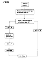
- the bulb change is required: for example, as illustrated in figure 4, if the maximum variation in the application time ⁇ T' (usually positive) which can be programmed on the microprocessor 14 is less than the actual variation T required, the change bulb 10a indication is automatically displayed on the viewer 16.
- the device therefore, fulfils the preset objectives thanks to its simple, rational configuration, which is, at the same time, extremely precise in controlling the light flux emitted by the pistol: the entire device being directly attached to the dental unit so as to allow the constant, direct control of lamp efficiency by the dental surgeon or assistant.
Abstract
Description
- The present invention relates to a control device for polymerising lamps, in particular for use on dental apparatus such as dental units.
- In the sector for auxiliary instruments or handpieces on the said dental units, it is known that polymerising lamps are used by the dental surgeon or assistant to reduce the time required to harden the ceramic pastes used for fillings by concentrating light upon the said paste and thus promoting the catalysis of the entire filling paste.
- The afore-mentioned lamps consist of a housing for light generating devices (the main component being a halogen bulb), said light being concentrated, filtered and directed into a "tube" defined by an optic fibre tip which is connected to one end of the housing so as to generate a light flux which exits the latter, concentrated in a given direction and with a constant intensity.
- Amongst the operations effected using such lamps, the phase which requires the greatest degree of supervision is the length of the polymerising treatment applied to the pastes using the lamp: in fact, the said phase determines a change in the state of the product, with the consequent diversification of the surface of the paste on the filling.
- The surfaces of the majority of pastes used for fillings shrink during polymerisation (due to the change of state), although these surfaces must perfectly fill the cavity in a tooth which has been operated upon. If they do not, the tooth cavity may be subject to infiltration or gaps with a significant risk of new decay, due to the excessive shrinkage of the paste.
- Therefore, to reduce the risk of fillings being infiltrated, dental surgeons use a method which envisages the creation of small successive layers of paste, precisely dosed, then polymerised with an equal degree of precision.
- The length of the polymerising treatment is normally controlled by fitting the afore-mentioned lamps with a timing device, that is to say, a device which measures the minimum treatment time required for the pastes to reach optimum hardness: the object being to minimise the patient's discomfort and avoid any unnecessary use of the lamp.
- It is, therefore, logical that with such a method, the dental surgeon must know exactly whether or not the light energy, that is to say the luminous intensity, supplied by the lamp during treatment remains unchanged, i.e.: is not reduced due to the natural "ageing" of the afore-mentioned halogen bulb: with this information, the dental surgeon can adjust the time factor, that is to say, lengthen the treatment on the paste to compensate a reduction in the light output of the lamp.
- Special apparatus for the measurement of the lamp light signal are currently used to control the luminous intensity of the polymerising lamp; however, the said apparatus are not attached to the dental unit and are normally supplied to service personnel, who control the lamp only during ordinary maintenance operations: this means that the lamp is only occasionally controlled, and the dental surgeon is obliged to adjust the treatment time in accordance with a theoretical reduction in the light output of the lamp, or to change the bulb earlier than scheduled.
- For this reason, the Applicant has designed and created a control device for polymerising lamps, configured in such a way that it is convenient, fast and easily used directly by the dental surgeon, allowing him/her to constantly control the efficiency of the lamp in the correct manner.
- The technical features of the present invention, in accordance with the aforesaid objects, are clearly illustrated in the claims herein, and the advantages of the said features are more clearly described in the detailed description below, with reference to the accompanying drawings, which illustrate an embodiment by way of example only, and in which:
- figure 1 is a block diagram illustrating two embodiments of the control device for polymerising lamps disclosed;
- figure 2 is a perspective view of a dental unit fitted with the device shown in figure 1, with some parts cut away to better illustrate others;
- figure 3 is a perspective view of a scaled-up detail from figure 2, and in particular an auxiliary instruments support including the device disclosed;
- figure 4 is a flow chart showing the operating phases of the device disclosed.
- With reference to the accompanying drawings, and especially figures 1 and 2, the control device for a polymerising lamp, denoted by the
number 8, is fitted to a dental unit R. - The basic components of the dental unit R include a
base 1 supporting a first vertical column 2, the latter being positioned at the side of a chair 3; on opposite sides of the vertical column 2 are a firstmain support 4 for operating instruments 5 (e.g.: a micro-motor, a turbo-drill, a syringe, etc., only partly shown here, being of the known type and not being part of the present invention), and asecond support 6 for auxiliary instruments 7 (such as the polymerising lamp, one or more saliva suction canules, a further syringe, etc.). The said first andsecond supports - As shown in figure 1, the afore-mentioned
polymerising lamp 8 consists of ahousing 9 withrelative grip 9a, containingmeans 10 for the generation of light comprised of ahalogen bulb 10a connected tomeans 20 for the supply of power to the latter. The light emitted by thebulb 10a is directed into atube 11 composed of optic fibres, so that it generates a light flux F directed towards the exterior of the saidtube 11, i.e.: the area of a tooth (not illustrated here) filled with a paste to be polymerised. - An integral component of the dental unit R are the
means 12 for the detection of the afore-mentioned light flux F, securely fixed to the dental unit at one of the above-mentioned operative control zones Z1 and Z2, more precisely on the second support 6 (as shown in figure 3). - The said
means 12 are able to detect the light flux F and convert it into an electrical signal SE which may be displayed on relative means 13, connected to the detector means 12, and again located at one of the operative zones Z1 and Z2. - As can be seen in figure 1, there are many possible embodiments of the device, all based on the assumption that the afore-mentioned means 12 for the detection of the light flux F are located on the
second support 6, and housed in the base of acavity 21 on the saidsecond support 6, specially designed to house the free end of thetube 11 of thelamp 8 from the outside when a control is required, so as to verify the intensity of the light flux. - In a first, simple embodiment, illustrated along the right-hand part of figure 1 (with a partly dashed line), the said detector means 12 may consist of a photometer whose output is connected to an
amplifier 22 for the signal SE at output. Theamplifier 22 may, in turn, be connected to a voltmeter (not illustrated) which may control, for example, a series ofLEDs 24 which define a graduated scale which, according to the signal sent from the photometer, display the intensity of the light flux F for the dental surgeon. - On dental units R of the latest generation, the detector means 12 may be connected to a processing unit or
microprocessor 14 which monitors the dental unit (embodiment illustrated in figure 1, on the left-hand side of the drawing); by means of arelative console 15, themicroprocessor 14 controls and activates aviewer 16 which constantly displays function data and accessory function data of the afore-mentionedmain instruments 5 andauxiliary instruments 7. - In this case, as shown in figure 1, the
means 12 for the detection of the light flux F may consist of transducer means for the said light flux F, such as a photodiode, whose output is connected to thesignal amplifier 22, in turn connected to themicroprocessor 14. The latter is able to send a relative signal SU, proportional to the afore-mentioned electrical signal SE sent by the transducer means 17, to theviewer 16, allowing the display of a data item equal to the quantity of light emitted by thepistol 8 in a unit of time, usually calculated in LUX (i.e.: in a unit of measure equal to the quantity of light, or in a number which is a percentage of the intensity in LUX). - A more complete variation on such a system may be to connect the
microprocessor 14 to means 18 for gauging the electrical signal SE sent by the light flux F transducer means, the microprocessor in turn sending a relative activation signal SA to timer means 19 and/or SA' to the afore-mentionedmeans 20 for the supply of power to thebulb 10a which both act upon thelamp 8, if the electrical signal SE detected is less than a preset reference signal SR on thegauge 18. - In other words, when the light flux F is not perfectly efficient, due to the natural ageing of the
bulb 10a, the lamp operating parameters are adjusted, that is to say, the (usual) treatment time or the power supplied to thebulb 10a, so as to obtain a correct polymerising treatment on the pastes. - The device, therefore, allows the dental surgeon to constantly control the perfect efficiency of the
polymerising lamp 8 by simply removing the lamp from thesupport 6 and pointing thetube 11 at theconsole 15 so that the light flux emitted is substantially perpendicular to the detector means 12 located within thecavity 21. - The control device is activated automatically, or by means of the
special selector 25 on theconsole 15, and detects the light flux F which exits thetube 11. - As shown in figure 4, if the measurement taken confirms the perfect efficiency of the lamp, displayed on the
viewer 16 or by theLEDs 24, the control operation is concluded; in contrast, if the control indicates a reduction in the light output of thehalogen bulb 10a, themicroprocessor 14 may make two types of adjustments: it may act upon therelative timer 19 of thelamp 8, extending the time memorised for the treatments, or increase the power supplied to the halogen bulb, said increase being proportional to the drop in the light output detected. - If the device is not controlled by a microprocessor (as illustrated in the first case), the dental surgeon must check the
LEDs 24, then directly adjust the parameters of thetimer 19 or increase the power supplied to thebulb 10a. - Obviously, in both cases, if the reduction in light output is too great, neither the timing or power supplied to the
bulb 10a are adjusted. Instead, the bulb change is required: for example, as illustrated in figure 4, if the maximum variation in the application time ΔT' (usually positive) which can be programmed on themicroprocessor 14 is less than the actual variation T required, thechange bulb 10a indication is automatically displayed on theviewer 16. - The device, therefore, fulfils the preset objectives thanks to its simple, rational configuration, which is, at the same time, extremely precise in controlling the light flux emitted by the pistol: the entire device being directly attached to the dental unit so as to allow the constant, direct control of lamp efficiency by the dental surgeon or assistant.
- Moreover, in the case of particularly advanced dental units, it is possible to obtain the automatic adjustment of the time - power supply variables by the microprocessor which is ready-programmed with the desired parameters.
- The present invention, thus designed for the said objects, may be subject to numerous variations, all encompassed by the original design concept, and all components may be replaced with technically equivalent parts.
Claims (6)
- A control device for polymerising lamps which can be used on dental units which include a base (1) supporting a first vertical column (2) positioned at the side of a chair (3), a first main support (4) for operating instruments (5) and a second support (6) for auxiliary instruments (7), constituting operative control zones (Z1, Z2), including the said polymerising lamp (8), consisting of a housing (9) containing means (10) for the generation of light which is directed into a tube (11) consisting of optic fibres, thus generating a light flux (F) directed towards the exterior of the said tube (11), characterised in that it includes, as components of the dental unit (R), means (12) for the detection of the said light flux (F), said means being securely fixed to the dental unit (R) in the said operative control zone (Z1, Z2), being configured so as to detect the light flux (F) and convert it into an electrical signal (SE); there being means (13) for the display of the said electrical signal (SE), also connected to the detector means (12).
- The device as described in claim 1, in which the dental unit (R) is fitted with a processing unit or microprocessor (14) for monitoring the dental unit (R), and which, by means of a relative console (15), activate a viewer (16) for the constant display of function data and accessory function data for the said main instruments (5) and auxiliary instruments (7), characterised in that the means (12) for the detection of the light flux (F) consist of transducer means (17) for the light flux (F) whose output is connected to the microprocessor (14), the latter being able to send a relative signal (SU), proportional to the electrical signal (SE) sent by the transducer means (17), to the viewer (16), thus allowing the display of a data item equal to the quantity of light emitted by the pistol (8) in a unit of time.
- The device as described in claim 2, characterised in that the microprocessor (14) is connected to means (18) for gauging the said electrical signal (SE) sent by the transducer means (17) for the light flux (F) and designed to send a relative activation signal (SA) to timing means (19) and/or means (20) for the supply of power to means (10) for the generation of light, both acting upon the said lamp (8), in correspondence with an electrical signal (SE) which is at least less than a reference signal (SR) which may be preset.
- The device as described in claim 2, characterised in that the detector means (12) and the transducer means (17) consist of a photodiode which is connected to the microprocessor (14).
- The device as described in claim 1, characterised in that the detector means (12) consist of a photometer.
- The device as described in claim 1, characterised in that the means (12) for the detection of the light flux (F) are positioned within the second support (6) for the auxiliary instruments (7); said means (12) being housed in the bottom of a cavity (21) in the second support (6), in which the free end of the tube (11) of the lamp (8) can be fitted from the outside.
Applications Claiming Priority (2)
| Application Number | Priority Date | Filing Date | Title |
|---|---|---|---|
| IT95BO000326A IT1279969B1 (en) | 1995-06-29 | 1995-06-29 | CONTROL DEVICE FOR POLYMERIZING LAMPS |
| ITBO950326 | 1995-06-29 |
Publications (2)
| Publication Number | Publication Date |
|---|---|
| EP0750889A1 true EP0750889A1 (en) | 1997-01-02 |
| EP0750889B1 EP0750889B1 (en) | 2001-12-05 |
Family
ID=11340698
Family Applications (1)
| Application Number | Title | Priority Date | Filing Date |
|---|---|---|---|
| EP19960830369 Expired - Lifetime EP0750889B1 (en) | 1995-06-29 | 1996-06-28 | A control device for polymerising lamps |
Country Status (4)
| Country | Link |
|---|---|
| EP (1) | EP0750889B1 (en) |
| DE (1) | DE69617539T2 (en) |
| ES (1) | ES2169218T3 (en) |
| IT (1) | IT1279969B1 (en) |
Cited By (10)
| Publication number | Priority date | Publication date | Assignee | Title |
|---|---|---|---|---|
| WO1999021505A1 (en) * | 1997-10-29 | 1999-05-06 | Bisco, Inc. | Dental composite light curing system |
| DE29800633U1 (en) * | 1998-01-15 | 1999-05-12 | Thera Ges Fuer Patente | Radiation device |
| WO1999037239A1 (en) * | 1998-01-27 | 1999-07-29 | Dmds Ltd. | Device for hardening composite materials used in the dental field |
| US6155823A (en) * | 1999-06-18 | 2000-12-05 | Bisco Inc. | Snap-on light shield for a dental composite light curing gun |
| EP0993810A3 (en) * | 1998-10-13 | 2001-06-27 | CASTELLINI S.p.A. | A polymerising lamp control unit |
| US6435872B1 (en) | 2000-02-02 | 2002-08-20 | Bisco, Inc. | Tapered light probe with non-circular output for a dental light curing unit |
| EP1236444A1 (en) * | 2001-02-14 | 2002-09-04 | Sirona Dental Systems GmbH | Device for the hardening of light-curing resins, especially of dental fill- and adhesive materials |
| US9072572B2 (en) | 2009-04-02 | 2015-07-07 | Kerr Corporation | Dental light device |
| US9572643B2 (en) | 1998-01-20 | 2017-02-21 | Kerr Corporation | Apparatus and method for curing materials with radiation |
| US9730778B2 (en) | 2009-04-02 | 2017-08-15 | Kerr Corporation | Curing light device |
Families Citing this family (1)
| Publication number | Priority date | Publication date | Assignee | Title |
|---|---|---|---|---|
| DE10309855B3 (en) * | 2003-03-06 | 2004-12-16 | Ivoclar Vivadent Ag | Test specimen, use of the test specimen and polymerization device |
Citations (3)
| Publication number | Priority date | Publication date | Assignee | Title |
|---|---|---|---|---|
| DE3411994A1 (en) * | 1984-03-31 | 1985-10-03 | Kulzer & Co Gmbh | Circuit arrangement for an irradiation lamp |
| DE3910438A1 (en) * | 1989-03-31 | 1990-10-04 | Kulzer & Co Gmbh | METHOD AND DEVICE FOR POLYMERIZING A BODY MADE OF DENTAL PLASTIC |
| US5233283A (en) * | 1991-12-04 | 1993-08-03 | John Kennedy | Light curing device power control system |
-
1995
- 1995-06-29 IT IT95BO000326A patent/IT1279969B1/en active IP Right Grant
-
1996
- 1996-06-28 DE DE1996617539 patent/DE69617539T2/en not_active Expired - Fee Related
- 1996-06-28 ES ES96830369T patent/ES2169218T3/en not_active Expired - Lifetime
- 1996-06-28 EP EP19960830369 patent/EP0750889B1/en not_active Expired - Lifetime
Patent Citations (3)
| Publication number | Priority date | Publication date | Assignee | Title |
|---|---|---|---|---|
| DE3411994A1 (en) * | 1984-03-31 | 1985-10-03 | Kulzer & Co Gmbh | Circuit arrangement for an irradiation lamp |
| DE3910438A1 (en) * | 1989-03-31 | 1990-10-04 | Kulzer & Co Gmbh | METHOD AND DEVICE FOR POLYMERIZING A BODY MADE OF DENTAL PLASTIC |
| US5233283A (en) * | 1991-12-04 | 1993-08-03 | John Kennedy | Light curing device power control system |
Cited By (16)
| Publication number | Priority date | Publication date | Assignee | Title |
|---|---|---|---|---|
| WO1999021505A1 (en) * | 1997-10-29 | 1999-05-06 | Bisco, Inc. | Dental composite light curing system |
| DE29800633U1 (en) * | 1998-01-15 | 1999-05-12 | Thera Ges Fuer Patente | Radiation device |
| US9572643B2 (en) | 1998-01-20 | 2017-02-21 | Kerr Corporation | Apparatus and method for curing materials with radiation |
| US9622839B2 (en) | 1998-01-20 | 2017-04-18 | Kerr Corporation | Apparatus and method for curing materials with radiation |
| WO1999037239A1 (en) * | 1998-01-27 | 1999-07-29 | Dmds Ltd. | Device for hardening composite materials used in the dental field |
| FR2773986A1 (en) * | 1998-01-27 | 1999-07-30 | Sed Societe D Exploit Dentaire | Dental composite materials hardening device |
| EP0993810A3 (en) * | 1998-10-13 | 2001-06-27 | CASTELLINI S.p.A. | A polymerising lamp control unit |
| US6155823A (en) * | 1999-06-18 | 2000-12-05 | Bisco Inc. | Snap-on light shield for a dental composite light curing gun |
| US6435872B1 (en) | 2000-02-02 | 2002-08-20 | Bisco, Inc. | Tapered light probe with non-circular output for a dental light curing unit |
| DE10107099A1 (en) * | 2001-02-14 | 2002-09-12 | Sirona Dental Systems Gmbh | Device for the polymerization of light-curing plastics, in particular dental filling or adhesive materials |
| DE10107099C2 (en) * | 2001-02-14 | 2003-12-11 | Sirona Dental Systems Gmbh | Device for the polymerization of light-curing plastics, in particular dental filling or adhesive materials |
| EP1236444A1 (en) * | 2001-02-14 | 2002-09-04 | Sirona Dental Systems GmbH | Device for the hardening of light-curing resins, especially of dental fill- and adhesive materials |
| US9072572B2 (en) | 2009-04-02 | 2015-07-07 | Kerr Corporation | Dental light device |
| US9693846B2 (en) | 2009-04-02 | 2017-07-04 | Kerr Corporation | Dental light device |
| US9730778B2 (en) | 2009-04-02 | 2017-08-15 | Kerr Corporation | Curing light device |
| US9987110B2 (en) | 2009-04-02 | 2018-06-05 | Kerr Corporation | Dental light device |
Also Published As
| Publication number | Publication date |
|---|---|
| ES2169218T3 (en) | 2002-07-01 |
| DE69617539D1 (en) | 2002-01-17 |
| ITBO950326A1 (en) | 1996-12-29 |
| DE69617539T2 (en) | 2002-08-01 |
| EP0750889B1 (en) | 2001-12-05 |
| IT1279969B1 (en) | 1997-12-23 |
Similar Documents
| Publication | Publication Date | Title |
|---|---|---|
| EP0750889B1 (en) | A control device for polymerising lamps | |
| US4952143A (en) | Dental bleaching instrument | |
| US6103203A (en) | System and method for controlling a light actuator to achieve partial polymerization | |
| US20070259309A1 (en) | Dental curing device and method with real-time cure indication | |
| US5912470A (en) | Process and an apparatus for the curing of light-sensitive polymeric compositions | |
| US5975895A (en) | Strobe light curing apparatus and method | |
| US6089740A (en) | Multipurpose dental lamp apparatus | |
| US6602074B1 (en) | Dental composite light curing system | |
| JP5426945B2 (en) | Apparatus for photocuring dental objects | |
| US20100140450A1 (en) | Automatic photopolymerisation device | |
| WO2009105888A1 (en) | Mfthod of calibrating light delivery systems, light delivery systems and radiometer for use therewith | |
| WO2006074525A1 (en) | Dental illumination device and method | |
| US6157661A (en) | System for producing a pulsed, varied and modulated laser output | |
| CA2312330A1 (en) | Dental apparatus with display | |
| US7354269B2 (en) | Electro-optical device for the photo-polymerization of composite material | |
| US10881491B2 (en) | Dental light curing device | |
| US6309216B1 (en) | Curing system for photohardenable materials | |
| EP0993810A2 (en) | A polymerising lamp control unit | |
| US20080274436A1 (en) | Optically regulated dental light unit | |
| US7167829B2 (en) | Curing lamp apparatus giving operating conditions with electronic voice | |
| CA1319283C (en) | Optical light guide | |
| CA1335631C (en) | Light curing apparatus and method | |
| JP2000024007A (en) | Photopolymerizer for dentist | |
| AU2002337851A1 (en) | Curing lamp apparatus with electronic voice | |
| EP2774574A1 (en) | Dental cord |
Legal Events
| Date | Code | Title | Description |
|---|---|---|---|
| PUAI | Public reference made under article 153(3) epc to a published international application that has entered the european phase |
Free format text: ORIGINAL CODE: 0009012 |
|
| AK | Designated contracting states |
Kind code of ref document: A1 Designated state(s): DE ES FR IT |
|
| 17P | Request for examination filed |
Effective date: 19970403 |
|
| 17Q | First examination report despatched |
Effective date: 19991217 |
|
| GRAG | Despatch of communication of intention to grant |
Free format text: ORIGINAL CODE: EPIDOS AGRA |
|
| GRAG | Despatch of communication of intention to grant |
Free format text: ORIGINAL CODE: EPIDOS AGRA |
|
| GRAG | Despatch of communication of intention to grant |
Free format text: ORIGINAL CODE: EPIDOS AGRA |
|
| GRAH | Despatch of communication of intention to grant a patent |
Free format text: ORIGINAL CODE: EPIDOS IGRA |
|
| GRAH | Despatch of communication of intention to grant a patent |
Free format text: ORIGINAL CODE: EPIDOS IGRA |
|
| GRAA | (expected) grant |
Free format text: ORIGINAL CODE: 0009210 |
|
| AK | Designated contracting states |
Kind code of ref document: B1 Designated state(s): DE ES FR IT |
|
| REF | Corresponds to: |
Ref document number: 69617539 Country of ref document: DE Date of ref document: 20020117 |
|
| ET | Fr: translation filed | ||
| REG | Reference to a national code |
Ref country code: ES Ref legal event code: FG2A Ref document number: 2169218 Country of ref document: ES Kind code of ref document: T3 |
|
| PLBE | No opposition filed within time limit |
Free format text: ORIGINAL CODE: 0009261 |
|
| STAA | Information on the status of an ep patent application or granted ep patent |
Free format text: STATUS: NO OPPOSITION FILED WITHIN TIME LIMIT |
|
| 26N | No opposition filed | ||
| PGFP | Annual fee paid to national office [announced via postgrant information from national office to epo] |
Ref country code: FR Payment date: 20030610 Year of fee payment: 8 |
|
| PGFP | Annual fee paid to national office [announced via postgrant information from national office to epo] |
Ref country code: ES Payment date: 20030619 Year of fee payment: 8 |
|
| PGFP | Annual fee paid to national office [announced via postgrant information from national office to epo] |
Ref country code: DE Payment date: 20030710 Year of fee payment: 8 |
|
| PG25 | Lapsed in a contracting state [announced via postgrant information from national office to epo] |
Ref country code: ES Free format text: LAPSE BECAUSE OF NON-PAYMENT OF DUE FEES Effective date: 20040629 |
|
| PG25 | Lapsed in a contracting state [announced via postgrant information from national office to epo] |
Ref country code: DE Free format text: LAPSE BECAUSE OF NON-PAYMENT OF DUE FEES Effective date: 20050101 |
|
| PG25 | Lapsed in a contracting state [announced via postgrant information from national office to epo] |
Ref country code: FR Free format text: LAPSE BECAUSE OF NON-PAYMENT OF DUE FEES Effective date: 20050228 |
|
| REG | Reference to a national code |
Ref country code: FR Ref legal event code: ST |
|
| PG25 | Lapsed in a contracting state [announced via postgrant information from national office to epo] |
Ref country code: IT Free format text: LAPSE BECAUSE OF NON-PAYMENT OF DUE FEES;WARNING: LAPSES OF ITALIAN PATENTS WITH EFFECTIVE DATE BEFORE 2007 MAY HAVE OCCURRED AT ANY TIME BEFORE 2007. THE CORRECT EFFECTIVE DATE MAY BE DIFFERENT FROM THE ONE RECORDED. Effective date: 20050628 |
|
| REG | Reference to a national code |
Ref country code: ES Ref legal event code: FD2A Effective date: 20040629 |