EP0748977A2 - Closing device for pipelines and device for placing the closing device - Google Patents
Closing device for pipelines and device for placing the closing device Download PDFInfo
- Publication number
- EP0748977A2 EP0748977A2 EP96101711A EP96101711A EP0748977A2 EP 0748977 A2 EP0748977 A2 EP 0748977A2 EP 96101711 A EP96101711 A EP 96101711A EP 96101711 A EP96101711 A EP 96101711A EP 0748977 A2 EP0748977 A2 EP 0748977A2
- Authority
- EP
- European Patent Office
- Prior art keywords
- shut
- bladder
- lock
- coupling member
- hose
- Prior art date
- Legal status (The legal status is an assumption and is not a legal conclusion. Google has not performed a legal analysis and makes no representation as to the accuracy of the status listed.)
- Withdrawn
Links
Images


Classifications
-
- F—MECHANICAL ENGINEERING; LIGHTING; HEATING; WEAPONS; BLASTING
- F16—ENGINEERING ELEMENTS AND UNITS; GENERAL MEASURES FOR PRODUCING AND MAINTAINING EFFECTIVE FUNCTIONING OF MACHINES OR INSTALLATIONS; THERMAL INSULATION IN GENERAL
- F16L—PIPES; JOINTS OR FITTINGS FOR PIPES; SUPPORTS FOR PIPES, CABLES OR PROTECTIVE TUBING; MEANS FOR THERMAL INSULATION IN GENERAL
- F16L55/00—Devices or appurtenances for use in, or in connection with, pipes or pipe systems
- F16L55/10—Means for stopping flow from or in pipes or hoses
- F16L55/12—Means for stopping flow from or in pipes or hoses by introducing into the pipe a member expandable in situ
- F16L55/128—Means for stopping flow from or in pipes or hoses by introducing into the pipe a member expandable in situ introduced axially into the pipe or hose
- F16L55/132—Means for stopping flow from or in pipes or hoses by introducing into the pipe a member expandable in situ introduced axially into the pipe or hose the closure device being a plug fixed by radially deforming the packing
- F16L55/134—Means for stopping flow from or in pipes or hoses by introducing into the pipe a member expandable in situ introduced axially into the pipe or hose the closure device being a plug fixed by radially deforming the packing by means of an inflatable packing
Definitions
- the invention relates to a shut-off device for pipelines, in particular for transporting gaseous media, with a bladder which can be expanded by a pressure medium and which is connected at least at one end to a hose, within which pressure lines or the like run.
- a device for setting the shut-off device in a pipe consisting of a coupling member which can be connected to a tapping bridge attached to the pipe and a tubular sluice which can be connected to the coupling member, the coupling member being provided with a shut-off valve and the sluice having a shut-off connection to the surroundings having.
- Blocking systems must be used that can be used to block lines without gas outflow.
- blocking systems include, for example, bladder setting devices or plug setting devices.
- a bladder setting device in which a cylindrical tube is provided inside, in which two bladders connected in series are arranged. These bubbles usually consist of thin-walled rubber and are composed of several individual parts vulcanized together. By combining several parts, there is a risk that the shut-off bladder will expand mainly in the longitudinal direction of the pipe when it is exposed to compressed air and finally burst before the filling pressure is reached. For this reason, the bladder - like a soccer ball - is surrounded by a shell made of a solid fabric, which gives the bladder its strength and shape when expanded.
- the firm fabric of the cover has hardly any elastic properties.
- the bladder cannot adapt to every pipe cross-section.
- an envelope with a bladder must be used which has an internal diameter.
- the surface of the shell is also structured. As a result of the structuring, the sheath cannot completely cover the inner wall of the pipeline to be shut off. Creep gas can consequently escape between the fabric and the inner wall of the pipeline, so that the known shut-off device forms a clear weak point here.
- shut-off devices are also known in which only one bladder is used. For safety reasons, however, in many cases only shut-off devices are used in which two bubbles arranged one behind the other and connected but which can be acted on separately are used. The pipeline space between the two bubbles can then be vented.
- a setting device with a lock which can be screwed onto a tapping sleeve placed around the pipeline.
- An axially displaceable tube is provided in the interior of the lock, which receives the shut-off device in its interior.
- the tube of the lock is pushed to the bottom of the previously drilled and shut-off pipeline, and then the bubbles therein are pushed out through holes provided in the lower region of the tube, which were previously rotated in the corresponding direction within the pipeline.
- the inner tube of the setting device is necessary in order to give the bubbles the direction to be specified so that they are not guided in the direction opposite to the shut-off point to be provided. A visual control from the outside of the course of the bubbles is naturally not possible.
- the pipeline to be shut off must first be drilled using a tapping device.
- the tapping device is first screwed onto a threaded coupling connected to a tapping bridge.
- the tapping bridge or the threaded coupling is provided with a ball valve so that the tapping point can be shut off after the pipe has been tapped and the tapping device can be unscrewed from the tapping bridge or the threaded coupling.
- the lock is screwed onto the tapping bridge, the ball valve is opened again and the shut-off device (bubbles) can be set as described above.
- a disadvantage of this system is that both the tapping device and the setting sluice have to be screwed onto the tapping bridge.
- screwing it on is very time consuming, Especially in cold winter months, this process is associated with high physical exertion for the personnel entrusted with the work.
- shut-off device is to be further developed so that the disadvantages shown are avoided.
- the device for setting the shut-off device is to be modified so that its use is considerably simplified and its safety is increased.
- the bladder is constructed in several parts and consists at least of an inner bladder which holds the pressure medium, an intermediate sheath surrounding the inner bladder and an outer bladder surrounding the intermediate sheath, the inner bladder and outer bladder being made of a rubber-elastic material and the intermediate sheath being made of a solid , shaping material are made.
- This multi-part construction of the bladder creates an extremely inexpensive shut-off device which has a high sealing effect. While the inner bladder is being expanded, the intermediate shell of the inner bladder forces a shape which is passed on to the rubber-elastic outer bladder until the outer bladder is sealed on the inner tube circumference. Since the outer shell also consists of a rubber-elastic material, it nestles completely against the inside diameter of the pipe and also compensates for unevenness.
- shut-off device can continue to be used even if the outer bladder should tear when it is set.
- the intermediate shell can take over the function of the outer bladder for a short time.
- the multiple parts offer a quick and inexpensive replacement for damaged ones Individual parts. A torn outer shell, for example, can easily be replaced before the shut-off device is used the next time.
- the intermediate sheath consists of an air-permeable fabric, which is particularly advantageously a corset.
- This material offers sufficient shaping strength and is still so flexible that it can take on sealing functions in an emergency.
- This intermediate casing prevents the inner bladder from expanding in an uncontrolled manner and is comparable to the outer casing of a football, for example.
- the hose has an intermediate, at least two-part, openable chamber, in which plug connectors can be accommodated for uncoupling the pressure lines from the bladder.
- plug connectors can be formed by mother / father connectors assigned to each pressure line.
- the chamber can preferably be formed by a screw connection consisting of two sleeves.
- the bladder In order to securely connect the bladder to the hose, it is provided at least at one of its ends in a transition area with a cross-sectional reduction on a tubular extension.
- the connection between bladder and hose can be connected by winding and knotting, in the manner in which fish hooks are attached to the fishing line.
- the hose preferably has a wire reinforcement running in the circumferential direction.
- the reinforcement can be wound spirally. This training ensures that the bladder (s) can be securely attached to the hose.
- the hose due to its length, the hose must be rolled up to and transported from the work area. The reinforcement forces the rolled-up hose onto a shape that lasts for a relatively long time, and thus a completely unwound hose will not run straight but in an arc.
- This arcuate course determines the direction in which the bladder (s) is (are) inserted when the shut-off device is set, that is to say when the bladder (s) are inserted into the pipeline.
- the setting device can be significantly simplified because the operators can determine the direction in which the bladder is set by appropriately guiding the hose without further auxiliary devices.
- a ball is connected to the plug closing the front end of the hose via an arcuate arm which is adapted to the hose curvature.
- the ball swings quickly and easily in the right direction of the pipeline.
- the device for setting the shut-off device in a pipeline is characterized in that the tubular lock can be inserted into the coupling member as far as it will go and can be connected by means of a thread-less tension lock.
- the tension lock consists of two diametrically arranged on the coupling member, which can be brought into the inner region of the coupling member with their clamping jaws, which engage in an outer circular groove of circular cross section, the locking elements with respect to the clamping jaws are mounted eccentrically so that the lock is pulled against a sealing ring lying on an axial shoulder in the coupling member during the delivery and the gas-tight connection is established.
- the tension lock designed in this way is relatively unaffected by dirt and easy to clean if necessary.
- the sealing ring is preferably made of rubber.
- the lock is equipped with an additional lockable connection, it can be flushed with inert gas.
- the sluice is provided in its upper region with a plurality of axially spaced sealing rings, the inner diameter of which is adapted to the outer diameter of the hose.
- the lock in the area of the sealing rings is provided with a grease nipple, through which grease can be injected if necessary, on the one hand to effect the seal and on the other hand to maintain the elasticity of the sealing rings.
- the entire system for tapping a gas-carrying pipeline and setting a shut-off device consisting of a coupling member that can be connected to a tapping bridge attached to the pipeline, a tapping device and a tubular sluice is simplified if both the tapping device and the sluice can be inserted into the coupling member as far as possible and can be connected to it by means of a thread-less tension lock. This makes it possible to remove the tapping device after drilling the pipeline and fitting the sluice to insert the shut-off device or the bubbles in a short time.
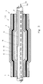
- FIG. 1 shows a shut-off device consisting of two bubbles 1 and 2 spaced apart along an axis 3.
- the bubbles 1 and 2 have a cylindrical jacket shape, the cylinder axis coinciding with the axis 3.
- transition regions 4 to tubular projections 5 with a smaller diameter are provided.
- the shut-off device is introduced with the bladder 2 ahead into a pipeline to be shut off, for example a gas line.
- the bubbles 1, 2 are constructed in several parts. Between the inner bladder 62 drawn on the tube 8 ′′ and the outer bladder 60 which takes over the actual sealing, an intermediate sheath 61 is arranged, which is made of a solid material which gives the inner bladder 62 the shape.
- This material is preferably air-permeable and a fabric from which corselets are usually made.
- the inner bladder and the outer bladder are made of a rubber-elastic material, a plastic or rubber. The shaping takes place exclusively through the intermediate shell 61, which prevents the inner bladder 62 from expanding in the longitudinal direction.
- the rear bladder 1 in the direction of insertion is closed in the area of the lugs 5 by plugs 6.
- the front bladder 2 is provided with a stopper 6 in the neck 5 facing the bladder 1.
- the other end of the bladder 2 is closed by a molded part 7.
- Both bubbles 1, 2 are connected by a flexible, but largely tensile and pressure-resistant hose 8 so that they can be inserted into the pipeline to be shut off.
- the tube 8 connects the opposite ends of the bladders 1 and 2 and is led out of the rear end of the bladder 1 in the insertion direction and is connected to a head part 40 via a screw connection 39 provided at its end.
- the part 8 'of the hose 8 lying between the bubbles 1 and 2 also has two openings 9a and 9b which are spaced apart from one another.
- the hose 8 can run through the bubbles 1, 2 continuously or each end in their tubular extensions 5, so that a separate hose is provided between the bubbles 1 and 2.
- the pressure line 10a is used to apply a pressure medium, preferably compressed air, to the bladder 1 and ends in the bladder 1.
- the pressure lines 10b to 10e are passed through the bladder 1.
- the pressure lines 10b and 10c lead to the two openings 9a and 9b.
- the pressure line 10d serves to pressurize the bladder 2 and ends in the bladder 2.
- the pressure line 10e is passed through the bladder 2 and adjoins the molded part 7.
- the pressure line 10e is used to detect the internal pipe pressure existing in front of the bladder introduced into the pipe. For this purpose, the pressure line 10e is connected via the head part 40 to a manometer (not shown here).
- the hose 8 ' opens into the tubular extension 5 of the bladder 2, as a result of which the hose 8' and the tubular extension 5 overlap approximately over the entire length of the extension 5.
- the outer diameter of the hose 8 corresponds approximately to the inner diameter of the extension 5.
- the plug 6 has a number of bores corresponding to the number of incoming pressure lines, into which the pressure lines are glued in a sealing manner. In the exemplary embodiment according to FIG. 1, it is only the pressure lines 10d and 10e.
- the bubbles 1, 2 are connected to the tube by means of binding, that is to say winding of a band, via the tubular projections 5.
- the binding or tying of the bubbles 1, 2 takes place in the manner in which fish hooks are also connected to the fishing line. For this purpose, several turns of a band are wrapped around the tubular extension and then the end of the band is pulled under the windings and lashed down. However, it is also possible to fix the tubular extension 5 of the bubbles 1 and 2 via a clamp 11. An airtight hollow body is created by appropriately closing the ends.
- the bladder 2 is closed with a molded part 7 having a shaft 12 in an analogous manner to how the plug 6 is inserted into the tubular extension 5 at the other end of the bladder 2.
- the pressure line 10e is glued into the inner region of an axial bore 13 through the shaft 12 of the molded part 7.
- the bore 13 opens out through an opening 14.
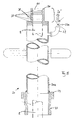
- the hose 8 ', 8' ' can be provided with a reinforcement 16 (steel wire) running in a spiral in the circumferential direction.
- a suitable selection of the reinforcement 16 gives the hose 8 such stability that the tubular extensions 5 of the bubbles 1 and 2 can be connected to the hose without a plug 6 in the hose 8, as shown in FIGS. 1 and 2 should be introduced.
- the hose 8 can consequently be guided in one piece through both bladders 1, 2 and its front end ends with the front end of the bladder 2.
- an opening 9c is provided in a hose 8 ′, 8 ′′, at which the pressure line 10 ends in order to be able to fill the bladder 1, 2 with compressed air.
- a plug 17 is introduced at its front end, which has a central bore 19. This bore 19 is connected to the pressure line 10e.
- a ball 15 is connected to the stopper 17 via a bent arm 18.
- the arm 18 is hollow and connects to the bore 19.
- the pressure line 10e is connected to the environment via an opening 18e provided in the arm 18, so that it can pass on the pressure present in the pipeline.
- the ball 15 is used to guide the bubbles 1, 2 in the correct direction when they are introduced into the pipeline when they hit the inner wall of the pipeline in a manner not shown here.
- a chamber 73 Upstream of the bubbles 1 and / or 2 is a chamber 73 formed by two sleeves 70, 71, which are screwed together.
- the pressure lines 10, 10a, 10b, ... are releasably accommodated via plug connectors 74, so that the pressure lines 10, 10a, 10b, ... behind the bubbles 1, 2 can be separated from the setting tool or other control devices.
- the sleeves 70, 71 are connected to the respective hose ends 8, for example by means of a clamp 80 or winding.
- a bayonet lock can also be used.
- FIG. 4 shows the tapping device 25 with the coupling member 21, which can be screwed via the external thread 36 provided on it to a tapping bridge, not shown here, which is connected to the pipeline.
- the coupling member 21 is tubular and has an upper region 29 with a larger diameter, which serves as a receiving part for the correspondingly designed counterpart for the coupling member 21.
- the clamping jaws 31, 31 a of the clamping elements 32, 32 a protrude into the interior of the coupling member 21.
- the clamping jaws 31, 31a form an eccentric due to the corresponding articulation of the clamping elements 32, 32a.
- the tapping device 25 has at its lower end the counterpart 24 designed for the coupling member 21.
- This counterpart 24 is sleeve-shaped and a tubular section 26 is soldered in its upper region.
- the outer circumference of the counterpart 24 is provided with a circumferential annular groove 23 with a circular arc cross section.
- the tapping device 25 is inserted with the counterpart 24 into the coupling member until its end 27 strikes the O-ring 35.
- the eccentric clamping jaws 31, 31 a slide into the annular groove 23 and pull the counterpart 24 and thus the drilling device 25 into the coupling member 21 in a gas-tight manner.
- the pipeline not shown here, can then be drilled through the drill pipe 28.
- tapping bridges The design of the tapping bridges is well known, so that it is here no detailed explanation is required.
- the tapping bridge is provided with a ball valve, via which the tapped pipe can be closed, so that no gas can escape through the tapping bridge when the tapping device 25 is removed from the coupling member 21.
- the tapping device 25 is sealed gas-tight even in its upper region.
- the drill pipe 28 is sealed off from the tapping device 25 via O-rings 28 '. Gas which has accumulated within the tapping device can be flared off via the connecting piece 22 'provided with a ball valve 22a before the tapping device 25 is separated from the coupling member 21.
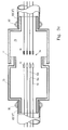
- FIG. 5 shows the sluice gate 20 for the shut-off device.
- the sluice gate 20 is also provided with a counterpart 24 to the coupling member 21.
- an annular shoulder is provided, into which a tube 20a is inserted and soldered.
- the upper region 20 'of the tube 20a is closed by a stopper 50 which has a bore 51 which is concentric with the tube 20a and into which a plurality of ring grooves are screwed and a plurality of sealing rings 37 are received axially spaced therein.
- the hose 8 running inside the lock 20 is indicated by a dash-dotted line.
- the sealing rings 37 are used for gas-tight sealing of the hose 8 in the lock 20.
- the hose 8 is drawn into the lock 20 from below (in the drawing) into the lock 20 before the screw connection 39 (FIG. 3 b) is fastened to it, via which the hose is then connected to the head piece 40.
- the lock 20 with the counterpart 24 is inserted into the coupling member 21 up to the stop and, as previously described, connected to the latter in a gas-tight manner via the tensioning elements 32, 32a.
- the ball valve of the tapping bridge not shown here, is opened, and the hose 8 is advanced, whereby the bubbles 1, 2 are pushed into the interior of the pipeline.
- the bubbles 1 and 2 in the pipeline completely are introduced, they are successively inflated via the pressure hoses 10a and 10d. As a result, they expand in the radial direction up to a multiple of their original diameter and come to rest on the inner wall of the pipeline.
- the strength of the elastic material and the wall thickness of the bubbles interact with their cylindrical jacket shape so that an uncontrolled expansion in the longitudinal direction of the tube is prevented.
- an overpressure is created in the area of part 8 'in the pipeline section between the two bubbles 1 and 2. This excess pressure can be reduced by venting through the two openings 9a, 9b and the associated pressure lines 10b, 10c.
- the pipeline section can also be flushed with an inert gas, for example nitrogen, via this venting device.
- the pressure present in the blocked pipeline can be measured via the molded part 7 or the plug 17 at the end of the bladder 2 and the pressure line 10e connected to it.
- the line 10e is connected via the head piece 40 to a manometer (not shown in more detail).
- the other pressure connections, which are connected by the head piece 40 are also not shown here.
- the opening 14 directed towards the tube wall prevents the opening from becoming clogged with dirt (see FIG. 2).
- connection connection 22 is also provided with a ball valve 22a.
- the stopper 50 is in the area between the sealing rings 37 with a Grease nipple 38 through which grease can be squeezed inside.
Abstract
Description
Die Erfindung betrifft eine Absperrvorrichtung für Rohrleitungen, insbesondere zum Transport gasförmiger Medien, mit einer durch ein Druckmedium aufweitbaren Blase, die zumindest an einem Ende mit einem Schlauch verbunden ist, innerhalb dessen Druckleitungen oder dergleichen verlaufen. Außerdem eine Vorrichtung zum Setzen der Absperrvorrichtung in einem Rohr, bestehend aus einem mit einer auf dein Rohr befestigten Anbohrbrücke verbindbaren Kupplungsglied und einer mit dem Kupplungsglied verbindbaren rohrförmigen Schleuse, wobei das Kupplungsglied mit einem absperrbaren Hahn versehen ist und die Schleuse einen absperrbaren Verbindungsanschluß mit der Umgebung aufweist.The invention relates to a shut-off device for pipelines, in particular for transporting gaseous media, with a bladder which can be expanded by a pressure medium and which is connected at least at one end to a hose, within which pressure lines or the like run. In addition, a device for setting the shut-off device in a pipe, consisting of a coupling member which can be connected to a tapping bridge attached to the pipe and a tubular sluice which can be connected to the coupling member, the coupling member being provided with a shut-off valve and the sluice having a shut-off connection to the surroundings having.
Bei Reparatur- oder Montagearbeiten insbesondere an in Betrieb befindlichen Gasleitungen ist es notwendig, die Leitung vor Beginn der Arbeiten vor und hinter der Reparatur- bzw. Montagestelle abzusperren. Gegebenenfalls muß auch ein Bypass eingerichtet werden.When carrying out repair or assembly work, in particular on gas pipelines in operation, it is necessary to shut off the pipeline before and before the repair or assembly site. If necessary, a bypass must also be set up.
Hierzu müssen besondere Maßnahmen zur Sperrung der Rohrquerschnitte vorgenommen werden. Dabei müssen Sperrsysteme zum Einsatz kommen, mit denen ohne Gasausströmung Leitungen gesperrt werden können. Zu solchen Sperrsystemen gehören zum Beispiel Blasensetzgeräte oder Stopfensetzgeräte.To do this, special measures must be taken to block the pipe cross-sections. Blocking systems must be used that can be used to block lines without gas outflow. Such blocking systems include, for example, bladder setting devices or plug setting devices.
In der Veröffentlichung "Neue DELIWA-Zeitschrift", Heft 2/88, Seite 48 ist ein Blasensetzgerät offenbart, bei dem im Inneren ein zylindrisches Rohr vorgesehen ist, in dem zwei hintereinander geschaltete Blasen angeordnet sind. Diese Blasen bestehen üblicherweise aus dünnwandigem Gummi und sind aus mehreren zusammen vulkanisierten Einzelteilen zusammengesetzt. Durch den Verbund mehrerer Teile besteht die Gefahr, daß sich die Absperrblase bei der Beaufschlagung mit Druckluft hauptsächlich in Rohrlängsrichtung ausdehnt und schließlich platzt, bevor der Fülldruck erreicht ist. Aus diesem Grund wird die Blase - wie ein Fußball - mit einer Hülle aus einem festen Gewebe, die der Blase in aufgeweitetem Zustand Festigkeit und Form gibt, umgeben.In the publication "Neue DELIWA-Zeitschrift",
Das feste Gewebe der Hülle weist kaum elastische Eigenschaften auf. Beim Befüllen kann sich die Blase folglich nicht an jeden Rohrleitungsquerschnitt anpassen. Für jede Rohrleitung muß deshalb eine deren Innendurchmesser angepaßte Hülle mit Blase verwendet werden. Außerdem ist die Oberfläche der Hülle strukturiert. Infolge der Strukturierung kann sich die Hülle nicht vollflächig an die Innenwand der abzusperrenden Rohrleitung anlegen. Zwischen dem Gewebe und der Innenwand der Rohrleitung kann folglich Schleichgas entweichen, so daß die bekannte Absperrvorrichtung hier eine deutliche Schwachstelle bildet.The firm fabric of the cover has hardly any elastic properties. When filling, the bladder cannot adapt to every pipe cross-section. For each pipeline, therefore, an envelope with a bladder must be used which has an internal diameter. The surface of the shell is also structured. As a result of the structuring, the sheath cannot completely cover the inner wall of the pipeline to be shut off. Creep gas can consequently escape between the fabric and the inner wall of the pipeline, so that the known shut-off device forms a clear weak point here.
Ein weiterer Nachteil ergibt sich aus der Reibung zwischen der Hülle und der Rohrleitung. Üblicherweise ist der Reibungskoeffizient so gering, daß die Haftreibung infolge des Anpreßdruckes nicht immer ausreichend ist, den sicheren Sitz der Absperrvorrichtung unter der Belastung des Innendrucks der Rohrleitung zu gewährleisten.Another disadvantage arises from the friction between the casing and the pipeline. Usually the coefficient of friction is so low that the static friction due to the contact pressure is not always sufficient to ensure the secure seating of the shut-off device under the load of the internal pressure of the pipeline.
Es sind auch Absperrvorrichtungen bekannt, bei denen nur eine Blase verwendet wird. Aus Sicherheitsgründen werden jedoch vielfach nur Absperrvorrichtungen verwendet, bei denen zwei hintereinander angeordnete und miteinander verbundene, jedoch getrennt beaufschlagbare Blasen verwendet werden. Der Rohrleitungsraum zwischen den beiden Blasen kann dann entlüftet werden.Shut-off devices are also known in which only one bladder is used. For safety reasons, however, in many cases only shut-off devices are used in which two bubbles arranged one behind the other and connected but which can be acted on separately are used. The pipeline space between the two bubbles can then be vented.
Zum Setzen der Absperrvorrichtung wird eine Setzvorrichtung mit einer Schleuse verwendet, die auf eine um die Rohrleitung gelegte Anbohrhülse aufgeschraubt werden kann. Im Inneren der Schleuse ist ein axial verschiebbares Rohr vorgesehen, das in seinem Innenbereich die Absperrvorrichtung aufnimmt. Das Rohr der Schleuse wird bis auf den Grund der zuvor angebohrten und abzusperrenden Rohrleitung geschoben, und dann die darin befindlichen Blasen durch in dem unteren Bereich des Rohres vorgesehene Bohrungen, die zuvor in die entsprechende Richtung innerhalb der Rohrleitung gedreht wurden, herausgeschoben. Das Innenrohr der Setzvorrichtung ist notwendig, um den Blasen die vorzugebende Richtung zu erteilen, damit diese nicht in die entgegen der vorzusehenden Absperrstelle verlaufende Richtung geführt werden. Eine visuelle Kontrolle von außen über den Verlauf der Blasen ist naturgemäß nicht möglich.To set the shut-off device, a setting device with a lock is used, which can be screwed onto a tapping sleeve placed around the pipeline. An axially displaceable tube is provided in the interior of the lock, which receives the shut-off device in its interior. The tube of the lock is pushed to the bottom of the previously drilled and shut-off pipeline, and then the bubbles therein are pushed out through holes provided in the lower region of the tube, which were previously rotated in the corresponding direction within the pipeline. The inner tube of the setting device is necessary in order to give the bubbles the direction to be specified so that they are not guided in the direction opposite to the shut-off point to be provided. A visual control from the outside of the course of the bubbles is naturally not possible.
Bevor die Setzvorrichtung zum Einsatz kommen kann, muß die abzusperrende Rohrleitung zunächst über eine Anbohrvorrichtung angebohrt werden. Hierzu wird zunächst die Anbohrvorrichtung auf eine mit einer Anbohrbrücke verbundenen Gewindekupplung aufgeschraubt. Die Anbohrbrücke oder die Gewindekupplung ist mit einem Kugelhahn versehen, so daß nach dem Anbohren der Rohrleitung die Anbohrstelle über den Hahn abgesperrt werden und die Anbohrvorrichtung aus der Anbohrbrücke bzw. der Gewindekupplung herausgeschraubt werden kann. Dann wird die Schleuse auf die Anbohrbrücke aufgeschraubt, der Kugelhahn wieder geöffnet und das zuvor beschriebene Setzen der Absperrvorrichtung (Blasen) kann erfolgen.Before the setting device can be used, the pipeline to be shut off must first be drilled using a tapping device. For this purpose, the tapping device is first screwed onto a threaded coupling connected to a tapping bridge. The tapping bridge or the threaded coupling is provided with a ball valve so that the tapping point can be shut off after the pipe has been tapped and the tapping device can be unscrewed from the tapping bridge or the threaded coupling. Then the lock is screwed onto the tapping bridge, the ball valve is opened again and the shut-off device (bubbles) can be set as described above.
Nachteilig bei diesem System ist es, daß sowohl die Anbohrvorrichtung als auch die Setzschleuse auf die Anbohrbrücke aufgeschraubt werden müssen. Zunächst einmal ist das Aufschrauben sehr zeitaufwendig, insbesondere in kalten Wintermonaten, ist dieser Vorgang für das mit den Arbeiten betraute Personal mit hohen körperlichen Anstrengungen verbunden. Außerdem besteht im Tiefbaubereich natürlich die Gefahr, daß die Gewinde verschmutzen. Wenn diese nicht sorgfältigst gereinigt werden, bevor die Teile zusammengeschraubt werden, ist dann nicht auszuschließen, daß das System nicht dicht ist und Gas entweichen kann.A disadvantage of this system is that both the tapping device and the setting sluice have to be screwed onto the tapping bridge. First of all, screwing it on is very time consuming, Especially in cold winter months, this process is associated with high physical exertion for the personnel entrusted with the work. In addition, there is of course a risk in the civil engineering sector that the threads become dirty. If these are not cleaned thoroughly before the parts are screwed together, it cannot be ruled out that the system is not leakproof and gas can escape.
Von dieser Problemstellung ausgehend soll eine gattungsgemäße Absperrvorrichtung so weiterentwickelt werden, daß die aufgezeigten Nachteile vermieden werden. Außerdem soll die Vorrichtung zum Setzen der Absperrvorrichtung so modifiziert werden, daß ihre Verwendung wesentlich vereinfacht und ihre Sicherheit erhöht wird.Starting from this problem, a generic shut-off device is to be further developed so that the disadvantages shown are avoided. In addition, the device for setting the shut-off device is to be modified so that its use is considerably simplified and its safety is increased.
Hinsichtlich der Absperrvorrichtung erfolgt die Problemlösung dadurch, daß die Blase mehrteilig aufgebaut ist und mindest aus einer das Druckmedium aufnehmenden Innenblase, einer die Innenblase umgebende Zwischenhülle und einer die Zwischenhülle umgebende Außenblase besteht, wobei Innenblase und Außenblase aus einem gummielastischen Werkstoff und die Zwischenhülle aus einem festen, formgebenden Werkstoff hergestellt sind.With regard to the shut-off device, the problem is solved in that the bladder is constructed in several parts and consists at least of an inner bladder which holds the pressure medium, an intermediate sheath surrounding the inner bladder and an outer bladder surrounding the intermediate sheath, the inner bladder and outer bladder being made of a rubber-elastic material and the intermediate sheath being made of a solid , shaping material are made.
Durch diesen mehrteiligen Aufbau der Blase wird eine äußerst kostengünstige Absperrvorrichtung geschaffen, die eine hohe Dichtwirkung aufweist. Während die Innenblase aufgeweitet wird, zwingt die Zwischenhülle der Innenblase eine Form auf, die an die gummielastische Außenblase so lange weitergegeben wird, bis über die Außenblase die Abdichtung am inneren Rohrumfang erfolgt. Da die Außenhülle ebenfalls aus einem gummielastischen Werkstoff besteht, schmiegt sie sich vollständig an den Rohrinnendurchmesser an und gleicht auch Unebenheiten aus.This multi-part construction of the bladder creates an extremely inexpensive shut-off device which has a high sealing effect. While the inner bladder is being expanded, the intermediate shell of the inner bladder forces a shape which is passed on to the rubber-elastic outer bladder until the outer bladder is sealed on the inner tube circumference. Since the outer shell also consists of a rubber-elastic material, it nestles completely against the inside diameter of the pipe and also compensates for unevenness.
Weiterhin vorteilhaft ist, daß auch dann mit der Absperrvorrichtung weitergearbeitet werden kann, wenn die Außenblase beim Setzen reißen sollte. Die Zwischenhülle kann für kurze Zeit durchaus die Funktion der Außenblase übernehmen. Außerdem bietet die Mehrteiligkeit einen raschen und kostengünstigen Ersatz etwa beschädigter Einzelteile. Eine gerissene Außenhülle beispielsweise kann leicht erneuert werden, bevor die Absperrvorrichtung das nächstemal eingesetzt wird.It is also advantageous that the shut-off device can continue to be used even if the outer bladder should tear when it is set. The intermediate shell can take over the function of the outer bladder for a short time. In addition, the multiple parts offer a quick and inexpensive replacement for damaged ones Individual parts. A torn outer shell, for example, can easily be replaced before the shut-off device is used the next time.
Insbesondere vorteilhaft ist es, wenn die Zwischenhülle aus einem luftdurchlässigen Gewebe besteht, das besonders vorteilhaft ein Miederstoff ist. Dieses Material bietet ausreichende formgebende Festigkeit und ist dennoch so flexibel, daß es im Notfall Dichtfunktionen übernehmen kann. Diese Zwischenhülle verhindert ein unkontrolliertes Aufweiten der Innenblase und ist mit der Außenhülle eines Fußballs beispielsweise vergleichbar.It is particularly advantageous if the intermediate sheath consists of an air-permeable fabric, which is particularly advantageously a corset. This material offers sufficient shaping strength and is still so flexible that it can take on sealing functions in an emergency. This intermediate casing prevents the inner bladder from expanding in an uncontrolled manner and is comparable to the outer casing of a football, for example.
Insbesondere vorteilhaft ist es, wenn der Schlauch eine zwischengeschaltete, zumindestens zweiteilige, öffenbare Kammer aufweist, in der Steckverbinder zum Abkuppeln der Druckleitungen von der Blase unterbringbar sind. Diese Steckverbinder können durch jeder Druckleitung zugeordnete Mutter-/Vater-Verbindungsstücke gebildet werden.It is particularly advantageous if the hose has an intermediate, at least two-part, openable chamber, in which plug connectors can be accommodated for uncoupling the pressure lines from the bladder. These connectors can be formed by mother / father connectors assigned to each pressure line.
Vorteilhaft an dieser Ausgestaltung ist es, daß die Blase der Absperrvorrichtung entsprechend des geforderten Einsatzzwecks leicht austauschbar ist, indem sie abgekuppelt und eine andere angekuppelt wird. Die Setzgeräte und das sonstige Zubehör der Absperrvorrichtung sind folglich universell verwendbar. Die Kammer kann vorzugsweise durch eine aus zwei Hülsen bestehende Schraubverbindung gebildet werden.It is advantageous in this embodiment that the bladder of the shut-off device can be easily replaced in accordance with the required purpose by uncoupling it and coupling another one. The setting tools and other accessories of the shut-off device can therefore be used universally. The chamber can preferably be formed by a screw connection consisting of two sleeves.
Um die Blase sicher mit dem Schlauch zu verbinden, ist sie zumindest an einem ihrer Enden in einem Übergangsbereich mit einer Querschnittsverringerung auf einen rohrförmigen Ansatz versehen. Über diesen Ansatz kann die Verbindung zwischen Blase und Schlauch durch Wickeln und Verknoten, nach der Art, wie Angelhaken an der Angelschnur befestigt werden, verbunden werden.In order to securely connect the bladder to the hose, it is provided at least at one of its ends in a transition area with a cross-sectional reduction on a tubular extension. Using this approach, the connection between bladder and hose can be connected by winding and knotting, in the manner in which fish hooks are attached to the fishing line.
Zur Erhöhung der Steifigkeit des Schlauches weist dieser vorzugsweise eine in Umfangsrichtung verlaufende Drahtarmierung auf. Die Armierung kann spiralförmig gewickelt sein. Diese Ausbildung stellt sicher, daß die Blase(n) fest auf dem Schlauch befestigbar ist (sind). Außerdem muß der Schlauch aufgrund seiner Länge aufgerollt zum Arbeitsbereich und von diesem weg transportiert werden. Durch die Armierung wird dem aufgerollten Schlauch eine Form aufgezwungen, die relativ lange anhält, und somit ein vollständig abgewickelter Schlauch nicht gerade, sondern bogenförmig verlaufen wird. Dieser bogenförmige Verlauf bestimmt beim Setzen der Absperrvorrichtung, das heißt dem Einführen der Blase(n) in die Rohrleitung die Richtung, in der die Blase(n) eingeführt wird (werden). Dadurch kann die Setzvorrichtung wesentlich vereinfacht werden, weil die Bedienpersonen durch entsprechende Führung des Schlauches ohne weitere Hilfsvorrichtungen die Richtung bestimmen können, in die die Blase gesetzt wird.To increase the rigidity of the hose, it preferably has a wire reinforcement running in the circumferential direction. The reinforcement can be wound spirally. This training ensures that the bladder (s) can be securely attached to the hose. In addition, due to its length, the hose must be rolled up to and transported from the work area. The reinforcement forces the rolled-up hose onto a shape that lasts for a relatively long time, and thus a completely unwound hose will not run straight but in an arc. This arcuate course determines the direction in which the bladder (s) is (are) inserted when the shut-off device is set, that is to say when the bladder (s) are inserted into the pipeline. As a result, the setting device can be significantly simplified because the operators can determine the direction in which the bladder is set by appropriately guiding the hose without further auxiliary devices.
Um das Setzen der Vorrichtung zu vereinfachen, ist es vorteilhaft, wenn mit dem das vordere Ende des Schlauchs verschließenden Stopfen eine Kugel über einen bogenförmig verlaufenden Arm verbunden ist, der der Schlauchkrümmung angepaßt ist. Die Kugel bewirkt dabei ein rasches und einfaches Einschwenken in die richtige Richtung der Rohrleitung.In order to simplify the setting of the device, it is advantageous if a ball is connected to the plug closing the front end of the hose via an arcuate arm which is adapted to the hose curvature. The ball swings quickly and easily in the right direction of the pipeline.
Die Vorrichtung zum Setzen der Absperrvorrichtung in einer Rohrleitung zeichnet sich dadurch aus, daß die rohrförmige Schleuse in das das Kupplungsglied auf Anschlag einsteckbar und mittels eines gewindelosen Spannverschlusses verbindbar ist.The device for setting the shut-off device in a pipeline is characterized in that the tubular lock can be inserted into the coupling member as far as it will go and can be connected by means of a thread-less tension lock.
Mit der so ausgebildeten Vorrichtung wird die Montage der Schleuse auf der Anbohrbrücke wesentlich vereinfacht. Dadurch erfolgt nicht nur eine Entlastung des Arbeitspersonals, wenn dessen Hände vor Kälte starr sind, sondern es wird auch die Zeit, die notwendig ist, um die Verbindung herzustellen, drastisch reduziert.With the device designed in this way, the assembly of the lock on the tapping bridge is considerably simplified. This not only relieves the strain on the workers when their hands are stiff from the cold, it also drastically reduces the time it takes to make the connection.
Vorzugsweise besteht der Spannverschluß aus zwei diametral am Kupplungsglied angeordneten, mit ihren Spannbacken in den Innenbereich des Kupplungsgliedes bringbaren Spannelementen, die in eine im Querschnitt kreisabschnittförmige äußere Ringnut der Schleuse eingreifen, wobei die Spannelemente in bezug auf die Spannbacken exzentrisch gelagert sind, so daß beim Zustellen die Schleuse gegen einen auf einem axialen Absatz im Kupplungsglied liegenden Dichtring gezogen und die gasdichte Verbindung hergestellt wird. Der so ausgebildete Spannverschluß ist relativ unanfällig gegen Verschmutzung und im Bedarfsfalle einfach zu reinigen. Vorzugsweise ist der Dichtring aus Gummi.Preferably, the tension lock consists of two diametrically arranged on the coupling member, which can be brought into the inner region of the coupling member with their clamping jaws, which engage in an outer circular groove of circular cross section, the locking elements with respect to the clamping jaws are mounted eccentrically so that the lock is pulled against a sealing ring lying on an axial shoulder in the coupling member during the delivery and the gas-tight connection is established. The tension lock designed in this way is relatively unaffected by dirt and easy to clean if necessary. The sealing ring is preferably made of rubber.
Wenn die Schleuse mit einem zusätzlichen absperrbaren Verbindungsanschluß versehen ist, kann sie mit Inertgas gespült werden.If the lock is equipped with an additional lockable connection, it can be flushed with inert gas.
Um eine gute Abdichtung zwischen der Schleuse und dem durch die Schleuse zu schiebenden Schlauch zu erreichen, ist die Schleuse in ihrem oberen Bereich mit einer Mehrzahl von axial beabstandeten Dichtringen versehen, die in ihrem Innendurchmesser dem Außendurchmesser des Schlauches angepaßt sind. Um eine Beschädigung der Dichtringe beim Durchführen des Schlauches zu vermeiden, ist die Schleuse im Bereich der Dichtringe mit einem Schmiernippel versehen, über den gegebenenfalls Fett eingepreßt werden kann, um einerseits die Abdichtung zu bewirken und andererseits die Elastizität der Dichtringe zu erhalten.In order to achieve a good seal between the sluice and the hose to be pushed through the sluice, the sluice is provided in its upper region with a plurality of axially spaced sealing rings, the inner diameter of which is adapted to the outer diameter of the hose. In order to avoid damage to the sealing rings when the hose is passed through, the lock in the area of the sealing rings is provided with a grease nipple, through which grease can be injected if necessary, on the one hand to effect the seal and on the other hand to maintain the elasticity of the sealing rings.
Das ganze System zum Anbohren einer gasführenden Rohrleitung und Setzen einer Absperrvorrichtung, bestehend aus einem mit einer auf der Rohrleitung befestigten Anbohrbrücke verbindbaren Kupplungsglied, einer Anbohrvorrichtung und einer rohrförmigen Schleuse wird dann vereinfacht, wenn sowohl die Anbohrvorrichtung als auch die Schleuse in das Kupplungsglied auf Anschlag einsteckbar und mittels eines gewindelosen Spannverschlusses mit diesem verbindbar sind. Das Entfernen der Anbohrvorrichtung nach dem Anbohren der Rohrleitung und Aufsetzen der Setzschleuse zum Einführen der Absperrvorrichtung bzw. der Blasen wird dadurch in kurzer Zeit möglich.The entire system for tapping a gas-carrying pipeline and setting a shut-off device, consisting of a coupling member that can be connected to a tapping bridge attached to the pipeline, a tapping device and a tubular sluice is simplified if both the tapping device and the sluice can be inserted into the coupling member as far as possible and can be connected to it by means of a thread-less tension lock. This makes it possible to remove the tapping device after drilling the pipeline and fitting the sluice to insert the shut-off device or the bubbles in a short time.
Anhand eines Ausführungsbeispieles soll die Erfindung nachfolgend näher erläutert werden. Es zeigt:
- Figur 1 -
- den Längsschnitt durch eine Absperrvorrichtung mit zwei hintereinander angeordneten Blasen;
- Figur 2 -
- den Längsschnitt durch die am vorderen Ende der Absperrvorrichtung liegende Blase in größerem Maßstab;
- Figur 3 -
- die schematische Darstellung der erfindungsgemäßen Blase im Längsschnitt;
- Figur 3a -
- den Längsschnitt durch ein Ausführungsbeispiel der erfindungsgemäßen Absperrvorrichtung mit zwei hintereinander angeordneten Blasen;
- Figur 3b -
- das obere Ende des Schlauches mit daran angeschlossenem Kopfteil;
- Figur 3c -
- die Einzelheit bei einer erfindungsgemäßen Ausgestaltung;
- Figur 4 -
- den Längsschnitt durch eine Anbohrvorrichtung mit dem zugehörigen Kupplungsglied;
- Figur 5 -
- den Längsschnitt durch die Schleuse der Setzvorrichtung
- Figur 6a -
- die Draufsicht auf das Kopfteil-Unterteil;
- Figur 6b -
- die Ansicht des Kopfteil-Unterteils;
- Figur 7a -
- die Draufsicht auf das Kopfteil-Oberteil;
- Figur 7b -
- die Seitenansicht des Kopfteil-Oberteils.
- Figure 1 -
- the longitudinal section through a shut-off device with two bubbles arranged one behind the other;
- Figure 2 -
- the longitudinal section through the bladder located at the front end of the shut-off device on a larger scale;
- Figure 3 -
- the schematic representation of the bladder according to the invention in longitudinal section;
- Figure 3a -
- the longitudinal section through an embodiment of the shut-off device according to the invention with two bubbles arranged one behind the other;
- Figure 3b -
- the upper end of the hose with the head part attached to it;
- Figure 3c -
- the detail in an embodiment according to the invention;
- Figure 4 -
- the longitudinal section through a tapping device with the associated coupling member;
- Figure 5 -
- the longitudinal section through the lock of the setting device
- Figure 6a -
- the top view of the head part lower part;
- Figure 6b -
- the view of the headboard lower part;
- Figure 7a -
- the top view of the headboard upper part;
- Figure 7b -
- the side view of the headboard upper part.
Figur 1 zeigt eine aus zwei entlang einer Achse 3 beabstandeten Blasen 1 und 2 bestehende Absperrvorrichtung. Die Blasen 1 und 2 weisen eine zylindermantelförmige Gestalt auf, wobei die Zylinderachse mit der Achse 3 zusammenfällt. An den Enden der Blasen 1 und 2 sind Übergangsbereiche 4 zu rohrförmigen Ansätzen 5 mit einem geringeren Durchmesser vorgesehen. Die Absperrvorrichtung wird mit der Blase 2 voraus in eine abzusperrende Rohrleitung, beispielsweise eine Gasleitung, eingeführt. Die Blasen 1, 2 sind wie Figur 3 zeigt, mehrteilig aufgebaut. Zwischen der auf dem Schlauch 8'' aufgezogenen Innenblase 62 und der die eigentliche Abdichtung übernehmenden Außenblase 60 ist eine Zwischenhülle 61 angeordnet, die aus einem festen, der Innenblase 62 die Form gebenden Werkstoff hergestellt ist. Dieser Werkstoff ist vorzugsweise luftdurchlässig und ein Gewebe, aus dem üblicherweise Mieder gefertigt werden. Die Innenblase und die Außenblase sind aus einem gummielastischen Werkstoff, einem Kunststoff oder Kautschuk hergestellt. Die Formgebung erfolgt ausschließlich durch die Zwischenhülle 61, die ein Aufweiten der Innenblase 62 in Längsrichtung verhindert.FIG. 1 shows a shut-off device consisting of two
Die in Einführungsrichtung hintere Blase 1 ist im Bereich der Ansätze 5 durch Stopfen 6 verschlossen. Die vordere Blase 2 ist in dem der Blase 1 zugewandten Ansatz 5 mit einem Stopfen 6 versehen. Das andere Ende der Blase 2 ist durch ein Formteil 7 verschlossen. Beide Blasen 1,2 sind durch einen flexiblen, weitgehend jedoch zug- und druckfesten Schlauch 8 miteinander so verbunden, daß sie in die abzusperrende Rohrleitung eingeführt werden können. Der Schlauch 8 verbindet die sich gegenüberliegenden Enden der Blasen 1 und 2 und wird aus dem in Einführrichtung hinteren Ende der Blase 1 herausgeführt und ist über eine an seinem Ende vorgesehene Verschraubung 39 mit einem Kopfteil 40 verbunden. Der zwischen den Blasen 1 und 2 liegende Teil 8' des Schlauches 8 weist außerdem zwei in Abstand voneinander liegende Öffnungen 9a und 9b auf. Der Schlauch 8 kann durch die Blasen 1,2 durchgängig hindurchlaufen oder jeweils in ihren rohrförmigen Ansätzen 5 enden, so daß zwischen den Blasen 1 und 2 ein separater Schlauch vorgesehen ist.The
Innerhalb des Schlauches 8 verlaufen fünf Druckleitungen 10a bis 10e, die die einzelnen Teile der Absperrvorrichtung über das Kopfteil 40 mit dem hier nicht näher dargestellten Steuerelement verbinden. Die Druckleitung 10a dient der Beaufschlagung der Blase 1 mit einem Druckmedium, vorzugsweise mit Druckluft und endet in der Blase 1. Die Druckleitungen 10b bis 10e sind durch die Blase 1 hindurchgeführt. Innerhalb des Teils 8' des Schlauchs 8 führen die Druckleitungen 10b und 10c zu den beiden Öffnungen 9a und 9b. Die Druckleitung 10d dient zur Druckbeaufschlagung der Blase 2 und endet in der Blase 2. Durch die Blase 2 hindurchgeführt ist die Druckleitung 10e und schließt sich an das Formteil 7 an. Die Druckleitung 10e dient zur Detektierung des vor der in die Rohrleitung eingeführten Blase anstehenden Rohrinnendruckes. Hierzu ist die Druckleitung 10e über das Kopfteil 40 an ein hier nicht näher dargestelltes Manometer angeschlossen.Five
Der Schlauch 8' mündet in den rohrförmigen Ansatz 5 der Blase 2, wodurch der Schlauch 8' und der rohrförmige Ansatz 5 sich etwa über die gesamte Länge des Ansatzes 5 überlappen. Der Außendurchmesser des Schlauchs 8 entspricht in etwa dem Innendurchmesser des Ansatzes 5. In diesem Überlappungsbereich kann sich im Schlauchende ein Stopfen 6 befinden, dessen Durchmesser dem Innendurchmesser des Schlauches 8' entspricht. Der Stopfen 6 weist eine der Anzahl der ankommenden Druckleitungen entsprechende Anzahl von Bohrungen auf, in die die Druckleitungen dichtend eingeklebt werden. Im Ausführungsbeispiel nach Figur 1 sind es lediglich die Druckleitungen 10d und 10e. Über die rohrförmigen Ansätze 5 werden die Blasen 1,2 mit dem Schlauch durch Binden, das heißt Wickeln eines Bandes verbunden. Das Binden oder Festbinden der Blasen 1,2 erfolgt in der Art, in der auch Angelhaken mit der Angelschnur verbunden werden. Hierzu werden mehrere Windungen eines Bandes um den rohrförmigen Ansatz herumgewickelt und dann das Bandende unter den Wicklungen hindurchgezogen und festgezurrt. Ebenso möglich ist es aber auch, den rohrförmigen Ansatz 5 der Blasen 1 und 2 über eine Schelle 11 zu fixieren. Durch das entsprechende Verschließen der Enden wird ein luftdichter Hohlkörper geschaffen.The hose 8 'opens into the
Am vorderen (in Einführrichtung betrachtet - auf der Zeichnung links) Ende wird die Blase 2 mit einem einen Schaft 12 aufweisenden Formteil 7 in analoger Weise geschlossen, so wie der Stopfen 6 in den rohrförmigen Ansatz 5 am anderen Ende der Blase 2 eingesetzt ist. In den inneren Bereich einer axialen Bohrung 13 durch den Schaft 12 des Formteils 7 ist die Druckleitung 10e eingeklebt. Die Bohrung 13 mündet über eine Öffnung 14 nach außen.At the front end (viewed in the direction of insertion - on the drawing on the left), the
Wie Figuren 3 und 3a zeigen, kann der Schlauch 8', 8'' mit einer spiralförmig in Umfangsrichtung verlaufenden Armierung 16 (Stahldraht) versehen sein. Durch eine geeignete Auswahl der Armierung 16 erhält der Schlauch 8 eine solche Stabilität, daß eine Verbindung der rohrförmigen Ansätze 5 der Blasen 1 und 2 mit dem Schlauch erfolgen kann, ohne daß dazu in den Schlauch 8 ein Stopfen 6 wie in Figuren 1 und 2 gezeigt eingeführt sein müßte. Der Schlauch 8 kann folglich einstückig durch beide Blasen 1,2 hindurchgeführt sein und sein vorderes Ende endet mit dem vorderen Ende der Blase 2. Im Inneren der Blase 1, 2 im ein Schlauch 8', 8'' eine Öffnung 9c vorgesehen, an der die Druckleitung 10 endet, um die Blase 1, 2 mit Druckluft befüllen zu können. Zum Verschließen des Schlauches 8 ist in diesem an seinem vorderen Ende ein Stopfen 17 eingebracht, der eine zentrale Bohrung 19 aufweist. Diese Bohrung 19 ist mit der Druckleitung 10e verbunden. Außerhalb des Schlauchs 8 ist mit dem Stopfen 17 eine Kugel 15 über einen gebogenen Arm 18 verbunden. Der Arm 18 ist hohl ausgeführt und schließt an die Bohrung 19 an. Über eine im Arm 18 vorgesehene Öffnung 18e ist die Druckleitung 10e mit der Umgebung verbunden, so daß sie den in der Rohrleitung anstehenden Druck weiterleiten kann. Die Kugel 15 dient dazu, die Blasen 1,2 beim Einführen in die Rohrleitung in die richtige Richtung zu leiten, wenn sie in hier nicht näher dargestellter Weise auf die Innenwandung der Rohrleitung auftrifft.As FIGS. 3 and 3a show, the hose 8 ', 8' 'can be provided with a reinforcement 16 (steel wire) running in a spiral in the circumferential direction. A suitable selection of the
Den Blasen 1 und/oder 2 vorgeordnet ist eine durch zwei Hülsen 70, 71, die miteinander verschraubt sind, gebildete Kammer 73. In dieser Kammer 73 sind die Druckleitungen 10, 10a, 10b, ... über Steckverbinder 74 lösbar untergebracht, so daß die Druckleitungen 10, 10a, 10b, ... hinter den Blasen 1, 2 vom Setzgerät bzw. den sonstigen Steuereinrichtungen getrennt werden können. Dadurch ist es möglich, dem Einsatzzweck entsprechende Blasen 1, 2 rasch einsetzen und mit den übrigen Steuergeräten verbinden zu können. Hierzu sind die Hülsen 70, 71 mit den jeweiligen Schlauchenden 8 beispielsweise über eine Schelle 80 oder auch Wickeln verbunden. Anstatt einer Verschraubung zwischen den Hülsen 70, 71 vorzusehen, kann auch ein Bajonettverschluß Verwendung finden.Upstream of the
Figur 4 zeigt die Anbohrvorrichtung 25 mit dem Kupplungsglied 21, das über das an ihm vorgesehene Außengewinde 36 mit einer hier nicht näher dargestellten Anbohrbrücke, die mit der Rohrleitung verbunden wird, verschraubbar ist. Das Kupplungsglied 21 ist rohrförmig ausgebildet und weist einen oberen Bereich 29 mit einem größeren Durchmesser auf, der als Aufnahmeteil für das entsprechend ausgebildete Gegenstück für das Kupplungsglied 21 dient. Die Spannbacken 31,31a der Spannelemente 32,32a ragen in den Innenbereich des Kupplungsgliedes 21 hinein. Die Spannbacken 31,31a bilden durch die entsprechende Anlenkung der Spannelemente 32,32a einen Exzenter. Der obere Bereich 29 des Kupplungsgliedes 21 endet nach unten gesehen an einem axialen Absatz 35 auf den ein O-Ring 34 aufgelegt ist.FIG. 4 shows the tapping
Die Anbohrvorrichtung 25 weist an ihrem unteren Ende das zum Kupplungsglied 21 ausgebildete Gegenstück 24 auf. Dieses Gegenstück 24 ist hülsenförmig ausgebildet und in seinem oberen Bereich ist ein rohrförmiger Abschnitt 26 eingelötet. Der äußere Umfang des Gegenstücks 24 ist mit einer im Querschnitt kreisbogenförmig ausgebildeten umlaufenden Ringnut 23 versehen. Die Anbohrvorrichtung 25 wird mit dem Gegenstück 24 in das Kupplungsglied so weit eingesteckt, bis sein Ende 27 auf den O-Ring 35 anschlägt. Durch nach Untendrücken der Spannelemente 32,32a schieben sich die exzentrischen Spannbacken 31,31a in die Ringnut 23 und ziehen das Gegenstück 24 und damit die Anbohrvorrichtung 25 gasdicht in das Kupplungsglied 21 ein. Über das Bohrgestänge 28 kann dann die hier nicht näher dargestellte Rohrleitung angebohrt werden. Die Ausbildung der Anbohrbrücken ist hinreichend bekannt, so daß es hier keiner eingehenden Erläuterung bedarf. Es sei jedoch darauf hingewiesen, daß die Anbohrbrücke mit einem Kugelhahn versehen ist, über den die angebohrte Rohrleitung verschließbar ist, so daß über die Anbohrbrücke kein Gas austreten kann, wenn die Anbohrvorrichtung 25 aus dem Kupplungsglied 21 herausgenommen wird. Die Anbohrvorrichtung 25 selbst in ihrem oberen Bereich gasdicht abgedichtet. Die Abdichtung des Bohrgestänges 28 gegenüber der Anbohrvorrichtung 25 erfolgt über O-Ringe 28'. Über den mit einem Kugelhahn 22a versehenen Anschlußstutzen 22' kann sich innerhalb der Anbohrvorrichtung angesammeltes Gas abgefackelt werden, bevor die Anbohrvorrichtung 25 vom Kupplungsglied 21 getrennt wird.The tapping
Figur 5 zeigt die Setzschleuse 20 für die Absperrvorrichtung. In ihrem unteren Bereich ist die Setzschleuse 20 ebenfalls mit einem Gegenstück 24 zum Kupplungsglied 21 versehen. Im oberen Bereich des Gegenstücks 24 ist ein ringförmiger Absatz vorgesehen, in den ein Rohr 20a eingesteckt und verlötet ist. Der obere Bereich 20' des Rohres 20a ist über einen Stopfen 50 verschlossen, der eine zum Rohr 20a konzentrische Bohrung 51 aufweist, in die mehrere Ringnuten eingedreht sind und hierin axial beabstandet mehrere Dichtringe 37 aufgenommen werden. Mit einer strichpunktierten Linie angedeutet ist der im Inneren der Schleuse 20 verlaufende Schlauch 8 dargestellt. Die Dichtringe 37 dienen zur gasdichten Abdichtung des Schlauchs 8 in der Schleuse 20.Figure 5 shows the
Der Schlauch 8 wird in die Schleuse 20 von (auf der Zeichnung) unten in die Schleuse 20 eingezogen, bevor die Verschraubung 39 (Figur 3b) an ihm befestigt wird, über die der Schlauch anschließend mit dem Kopfstück 40 verbunden wird.The
Zum Setzen der Absperrvorrichtung wird die Schleuse 20 mit dem Gegenstück 24 in das Kupplungsglied 21 bis zum Anschlag eingesetzt und wie zuvor beschrieben über die Spannelemente 32,32a gasdicht mit diesem verbunden. Der Kugelhahn der hier nicht dargestellten Anbohrbrücke wird geöffnet, und der Schlauch 8 vorgeschoben, wodurch die Blasen 1,2 in das Innere der Rohrleitung eingeschoben werden. Wenn die Blasen 1 und 2 in die Rohrleitung vollständig eingeführt sind, werden sie nacheinander über die Druckschläuche 10a und 10d aufgeblasen. Dadurch dehnen sie sich in radialer Richtung bis zu einem Vielfachen ihres ursprünglichen Durchmessers und kommen zur Anlage an der Innenwand der Rohrleitung. Die Festigkeit des elastischen Materials und die Wanddicke der Blasen wirken dabei mit deren zylindermantelförmigen Gestalt so zusammen, daß eine unkontrollierte Ausdehnung in Rohrlängsrichtung verhindert wird. Während des Füllens der zweiten Blase entsteht im Bereich des Teiles 8' im Rohrleitungsabschnitt zwischen den beiden Blasen 1 und 2 ein Überdruck. Durch Entlüften über die beiden Öffnungen 9a,9b und die zugehörigen Druckleitungen 10b,10c läßt sich dieser Überdruck abbauen. Über diese Entlüftungseinrichtung kann der Rohrleitungsabschnitt auch mit einem Inertgas, beispielsweise Stickstoff gespült werden. Über das Formteil 7 bzw. den Stopfen 17 am Ende der Blase 2 und die daran angeschlossene Druckleitung 10e kann der anstehende Druck in der abgesperrten Rohrleitung gemessen werden. Über das Kopfstück 40 ist die Leitung 10e hierzu mit einem nicht näher dargestellten Manometer verbunden. Auch die übrigen Druckanschlüsse, die durch das Kopfstück 40 verbunden werden, sind hier nicht näher dargestellt.To set the shut-off device, the
Die zur Rohrwandung hin gerichtete Öffnung 14 verhindert in Zusammenwirken mit der besonderen Gestaltung des Formteils ein Zusetzen der Öffnung mit Schmutz (vergleiche Figur 2).In cooperation with the special design of the molded part, the
Nach Beendigung der Arbeiten an der Rohrleitung wird die Druckluft aus den Blasen 1 und 2 abgelassen. Dadurch nehmen sie wieder ihre ursprüngliche Form an und lassen sich so über den Schlauch 8 aus der Rohrleitung wieder herausziehen.After completing work on the pipeline, the compressed air is released from
Über den Verbindungsanschluß 22 kann vor Entfernen der Setzschleuse 20 vom Kupplungsglied 21 wie bereits zuvor beschrieben darin befindliches Gas abgefackelt werden. Hierzu ist der Verbindungsanschluß 22 ebenfalls mit einem Kugelhahn 22a versehen. Um die Abdichtung zwischen Schlauch 8 und den Dichtringen 37 wirksam einzuhalten und eine Versprödung der Dichtringe 37 zu verhindern, ist der Stopfen 50 im Bereich zwischen den Dichtringen 37 mit einem Schmiernippel 38, über den Fett ins Innere gequetscht werden kann, versehen.Gas can be flared off via the
- 11
- Blasebladder
- 22nd
- Blasebladder
- 33rd
- Achseaxis
- 44th
- ÜbergangsbereichTransition area
- 55
- rohrförmiger Ansatztubular neck
- 66
- StopfenPlug
- 6a6a
- StopfenPlug
- 77
- FormteilMolding
- 88th
- Schlauchtube
- 8'8th'
-
Schlauch zwischen Blase 1 und 2Hose between
bladder - 8''8th''
- BlasengestängeBladder poles
- 9a9a
- Öffnungopening
- 9b9b
- Öffnungopening
- 9c9c
- Öffnungopening
- 10a bis e10a to e
- DruckleitungPressure line
- 1111
- Schelleclamp
- 1212th
- Schaftshaft
- 1313
- Bohrungdrilling
- 1414
- Öffnungopening
- 1515
- KugelBullet
- 1616
- DrahtarmierungWire armouring
- 1717th
- StopfenPlug
- 1818th
- Armpoor
- 1919th
- Bohrungdrilling
- 2020th
- Schleuselock
- 20a20a
- Rohrpipe
- 20'20 '
- oberer Bereich von 20upper range of 20
- 2121
- KupplungsgliedCoupling link
- 2222
- VerbindungsanschlußConnection connector
- 22'22 '
- VerbindungsanschlußConnection connector
- 2323
- RingnutRing groove
- 2424th
- Gegenstück zu 21Counterpart to 21
- 2525th
- AnbohrvorrichtungDrilling device
- 2626
- rohrförmiger Abschnitttubular section
- 2727
- unteres Endelower end
- 2828
- BohrgestängeDrill pipe
- 28'28 '
- O-RingO-ring
- 2929
- oberer Bereichupper area
- 3030th
- SpannverschlußDraw latch
- 3131
- SpannbackeJaw
- 31a31a
- SpannbackeJaw
- 3232
- SpannelementClamping element
- 32a32a
- SpannelementClamping element
- 3434
- DichtringSealing ring
- 3535
- Absatzparagraph
- 3636
- AußengewindeExternal thread
- 3737
- DichtringSealing ring
- 3838
- SchmiernippelGrease nipple
- 3939
- VerschraubungScrew connection
- 4040
- KopfteilHeadboard
- 5050
- StopfenPlug
- 5151
- Bohrungdrilling
- 6060
- AußenblaseOuter bladder
- 6161
- ZwischenhülleIntermediate cover
- 6262
- InnenblaseInner bladder
- 7070
- HülseSleeve
- 7171
- HülseSleeve
- 7373
- Kammerchamber
- 7474
- SteckverbindungConnector
- 7575
- VaterteilFather part
- 7676
- MutterteilMother part
- 8080
- Schelleclamp
Claims (17)
Applications Claiming Priority (2)
| Application Number | Priority Date | Filing Date | Title |
|---|---|---|---|
| DE19521834A DE19521834C2 (en) | 1994-08-01 | 1995-06-16 | Shut-off device for pipes and device for setting the shut-off device |
| DE19521834 | 1995-06-16 |
Publications (2)
| Publication Number | Publication Date |
|---|---|
| EP0748977A2 true EP0748977A2 (en) | 1996-12-18 |
| EP0748977A3 EP0748977A3 (en) | 1997-01-08 |
Family
ID=7764472
Family Applications (1)
| Application Number | Title | Priority Date | Filing Date |
|---|---|---|---|
| EP96101711A Withdrawn EP0748977A3 (en) | 1995-06-16 | 1996-02-07 | Closing device for pipelines and device for placing the closing device |
Country Status (1)
| Country | Link |
|---|---|
| EP (1) | EP0748977A3 (en) |
Cited By (3)
| Publication number | Priority date | Publication date | Assignee | Title |
|---|---|---|---|---|
| WO2000047928A1 (en) * | 1999-02-11 | 2000-08-17 | Glynwed Pipe Systems Limited | Apparatus for stopping flow through a pipe |
| CN109882674A (en) * | 2019-03-28 | 2019-06-14 | 浙江海洋大学 | A kind of water tubular union |
| EP3693648A4 (en) * | 2017-10-02 | 2021-05-05 | Aleksandr Georgievich Chuiko | Device for the internal monolithic insulation of a welded pipeline joint |
Citations (11)
| Publication number | Priority date | Publication date | Assignee | Title |
|---|---|---|---|---|
| US3618639A (en) * | 1969-11-24 | 1971-11-09 | Cues Inc | Packer for sealing pipe leaks |
| US4013097A (en) * | 1974-06-28 | 1977-03-22 | Anthony Louis Calandra | Apparatus and method for damming a pipeline |
| DE2713993A1 (en) * | 1977-03-30 | 1978-10-05 | Herbert Lux | Gas pipe drilling equipment - has housing accommodating drill clamped to pipe and with sliding shutter to close tapped hole |
| US4155373A (en) * | 1976-12-06 | 1979-05-22 | Digiovanni Bernard A | Method for shutting off gas flow in plastic pipes |
| FR2429957A1 (en) * | 1978-06-28 | 1980-01-25 | Kleber Colombes | Rapid action spigot and socket pipe coupling - contains inflatable sleeve which has overlapping reinforcing layers sandwiching rubber core |
| DE3145284A1 (en) * | 1981-11-14 | 1983-05-19 | IBS Nagel GmbH & Co Spezialarmaturen, 5630 Remscheid | Device for shutting off gas lines |
| FR2589980A1 (en) * | 1985-11-08 | 1987-05-15 | Leviel Christian | Expandable device for blocking off a pipeline |
| DE3719395A1 (en) * | 1987-06-11 | 1988-12-22 | Waf Gmbh Absperrgeraete Und Ap | Device for shutting off pipelines |
| EP0529671A2 (en) * | 1991-08-30 | 1993-03-03 | WILHELM KNEITZ & CO. AG | Laminated textile material, especially for technical applications |
| DE9412355U1 (en) * | 1994-08-01 | 1994-09-29 | Ullrich Gmbh & Co Kg K | Shut-off device for pipelines for the transport of liquid or gaseous media |
| WO1995017642A1 (en) * | 1993-12-21 | 1995-06-29 | Vinidex Tubemakers Pty. Limited | Expandable plug and control method |
-
1996
- 1996-02-07 EP EP96101711A patent/EP0748977A3/en not_active Withdrawn
Patent Citations (11)
| Publication number | Priority date | Publication date | Assignee | Title |
|---|---|---|---|---|
| US3618639A (en) * | 1969-11-24 | 1971-11-09 | Cues Inc | Packer for sealing pipe leaks |
| US4013097A (en) * | 1974-06-28 | 1977-03-22 | Anthony Louis Calandra | Apparatus and method for damming a pipeline |
| US4155373A (en) * | 1976-12-06 | 1979-05-22 | Digiovanni Bernard A | Method for shutting off gas flow in plastic pipes |
| DE2713993A1 (en) * | 1977-03-30 | 1978-10-05 | Herbert Lux | Gas pipe drilling equipment - has housing accommodating drill clamped to pipe and with sliding shutter to close tapped hole |
| FR2429957A1 (en) * | 1978-06-28 | 1980-01-25 | Kleber Colombes | Rapid action spigot and socket pipe coupling - contains inflatable sleeve which has overlapping reinforcing layers sandwiching rubber core |
| DE3145284A1 (en) * | 1981-11-14 | 1983-05-19 | IBS Nagel GmbH & Co Spezialarmaturen, 5630 Remscheid | Device for shutting off gas lines |
| FR2589980A1 (en) * | 1985-11-08 | 1987-05-15 | Leviel Christian | Expandable device for blocking off a pipeline |
| DE3719395A1 (en) * | 1987-06-11 | 1988-12-22 | Waf Gmbh Absperrgeraete Und Ap | Device for shutting off pipelines |
| EP0529671A2 (en) * | 1991-08-30 | 1993-03-03 | WILHELM KNEITZ & CO. AG | Laminated textile material, especially for technical applications |
| WO1995017642A1 (en) * | 1993-12-21 | 1995-06-29 | Vinidex Tubemakers Pty. Limited | Expandable plug and control method |
| DE9412355U1 (en) * | 1994-08-01 | 1994-09-29 | Ullrich Gmbh & Co Kg K | Shut-off device for pipelines for the transport of liquid or gaseous media |
Non-Patent Citations (1)
| Title |
|---|
| NEUE DELIWA-ZEITSCHRIFT, Bd. 2, Nr. 88, Februar 1988, HANNOVER, DE, Seiten 46-51, XP002010845 "Arbeiten an Gasleitungen" * |
Cited By (5)
| Publication number | Priority date | Publication date | Assignee | Title |
|---|---|---|---|---|
| WO2000047928A1 (en) * | 1999-02-11 | 2000-08-17 | Glynwed Pipe Systems Limited | Apparatus for stopping flow through a pipe |
| EP3693648A4 (en) * | 2017-10-02 | 2021-05-05 | Aleksandr Georgievich Chuiko | Device for the internal monolithic insulation of a welded pipeline joint |
| US11644128B2 (en) | 2017-10-02 | 2023-05-09 | Aleksandr Georgievich CHUIKO | Device for the internal monolithic insulation of a welded pipeline joint |
| CN109882674A (en) * | 2019-03-28 | 2019-06-14 | 浙江海洋大学 | A kind of water tubular union |
| CN109882674B (en) * | 2019-03-28 | 2024-02-23 | 浙江海洋大学 | Water pipe connecting piece |
Also Published As
| Publication number | Publication date |
|---|---|
| EP0748977A3 (en) | 1997-01-08 |
Similar Documents
| Publication | Publication Date | Title |
|---|---|---|
| DE2711408A1 (en) | PRESSURE END COUPLING FOR NON-METALLIC, FLEXIBLE PIPING | |
| EP0327494B1 (en) | Safety plug coupling, especially for pressurized-air conduits | |
| DE60204287T2 (en) | COUPLING FOR CONNECTING A TUBE OR TUBE BY PUSHING | |
| DE3743170C1 (en) | Pipe screw-connection | |
| DE1425487A1 (en) | Pressure collector for pressure fluids | |
| DE19521834C2 (en) | Shut-off device for pipes and device for setting the shut-off device | |
| DE2248589C3 (en) | Electrically insulating pipe coupling | |
| DE102014109799A1 (en) | pipe coupling | |
| EP0748977A2 (en) | Closing device for pipelines and device for placing the closing device | |
| DE7626310U1 (en) | PIPE ELEMENT WITH HYDRAULIC END SEAL USING A MOVABLE DIFFERENTIAL BODY | |
| DE3536297A1 (en) | HOSE AND CLUTCH COMPREHENSIVE ARRANGEMENT AND HOSE COUPLING HERE | |
| DE2650371C3 (en) | Coupling sleeve made of plastic for a tensile pipe connection | |
| WO2008125188A1 (en) | Short-body connector for fluid couplings | |
| DE1970807U (en) | HOSE SOCKET. | |
| DE4211959A1 (en) | Connection fitting for metallic pipes - incorporates axial bore with female thread and plane section with sealing groove | |
| DE3724372A1 (en) | PIPE SEALING PILLOW WITH INLET | |
| DE2611175A1 (en) | Radial toggle lever clamp for hose coupling - has internal flanges for clamping hose to adaptor sleeve | |
| DE851290C (en) | Hose connection | |
| DE60216093T2 (en) | pipe connection | |
| EP0392148B1 (en) | Pipe connection | |
| DE816042C (en) | Pipe connection, especially for elastic pipes and hoses | |
| DE2650392C3 (en) | Cable locking sleeve | |
| DE840490C (en) | Fitting for hoses u. like | |
| DE8132177U1 (en) | "SHUT-OFF BLADDER FOR GAS PIPES" | |
| DE3009852C2 (en) | Fitting for hoses with corded or braided inserts |
Legal Events
| Date | Code | Title | Description |
|---|---|---|---|
| PUAI | Public reference made under article 153(3) epc to a published international application that has entered the european phase |
Free format text: ORIGINAL CODE: 0009012 |
|
| PUAL | Search report despatched |
Free format text: ORIGINAL CODE: 0009013 |
|
| AK | Designated contracting states |
Kind code of ref document: A2 Designated state(s): AT BE DE FR NL |
|
| AK | Designated contracting states |
Kind code of ref document: A3 Designated state(s): AT BE DE FR NL |
|
| 17P | Request for examination filed |
Effective date: 19961219 |
|
| 17Q | First examination report despatched |
Effective date: 19990113 |
|
| STAA | Information on the status of an ep patent application or granted ep patent |
Free format text: STATUS: THE APPLICATION IS DEEMED TO BE WITHDRAWN |
|
| 18D | Application deemed to be withdrawn |
Effective date: 19991130 |