EP0748149B1 - Plasma arc torch having water injection nozzle assembly - Google Patents
Plasma arc torch having water injection nozzle assembly Download PDFInfo
- Publication number
- EP0748149B1 EP0748149B1 EP96302863A EP96302863A EP0748149B1 EP 0748149 B1 EP0748149 B1 EP 0748149B1 EP 96302863 A EP96302863 A EP 96302863A EP 96302863 A EP96302863 A EP 96302863A EP 0748149 B1 EP0748149 B1 EP 0748149B1
- Authority
- EP
- European Patent Office
- Prior art keywords
- nozzle
- nozzle assembly
- bore
- annular
- base
- Prior art date
- Legal status (The legal status is an assumption and is not a legal conclusion. Google has not performed a legal analysis and makes no representation as to the accuracy of the status listed.)
- Expired - Lifetime
Links
Images
Classifications
-
- H—ELECTRICITY
- H05—ELECTRIC TECHNIQUES NOT OTHERWISE PROVIDED FOR
- H05H—PLASMA TECHNIQUE; PRODUCTION OF ACCELERATED ELECTRICALLY-CHARGED PARTICLES OR OF NEUTRONS; PRODUCTION OR ACCELERATION OF NEUTRAL MOLECULAR OR ATOMIC BEAMS
- H05H1/00—Generating plasma; Handling plasma
- H05H1/24—Generating plasma
- H05H1/26—Plasma torches
- H05H1/32—Plasma torches using an arc
- H05H1/34—Details, e.g. electrodes, nozzles
- H05H1/3405—Arrangements for stabilising or constricting the arc, e.g. by an additional gas flow
-
- H—ELECTRICITY
- H05—ELECTRIC TECHNIQUES NOT OTHERWISE PROVIDED FOR
- H05H—PLASMA TECHNIQUE; PRODUCTION OF ACCELERATED ELECTRICALLY-CHARGED PARTICLES OR OF NEUTRONS; PRODUCTION OR ACCELERATION OF NEUTRAL MOLECULAR OR ATOMIC BEAMS
- H05H1/00—Generating plasma; Handling plasma
- H05H1/24—Generating plasma
- H05H1/26—Plasma torches
- H05H1/32—Plasma torches using an arc
- H05H1/34—Details, e.g. electrodes, nozzles
- H05H1/3421—Transferred arc or pilot arc mode
-
- H—ELECTRICITY
- H05—ELECTRIC TECHNIQUES NOT OTHERWISE PROVIDED FOR
- H05H—PLASMA TECHNIQUE; PRODUCTION OF ACCELERATED ELECTRICALLY-CHARGED PARTICLES OR OF NEUTRONS; PRODUCTION OR ACCELERATION OF NEUTRAL MOLECULAR OR ATOMIC BEAMS
- H05H1/00—Generating plasma; Handling plasma
- H05H1/24—Generating plasma
- H05H1/26—Plasma torches
- H05H1/32—Plasma torches using an arc
- H05H1/34—Details, e.g. electrodes, nozzles
- H05H1/3436—Hollow cathodes with internal coolant flow
-
- H—ELECTRICITY
- H05—ELECTRIC TECHNIQUES NOT OTHERWISE PROVIDED FOR
- H05H—PLASMA TECHNIQUE; PRODUCTION OF ACCELERATED ELECTRICALLY-CHARGED PARTICLES OR OF NEUTRONS; PRODUCTION OR ACCELERATION OF NEUTRAL MOLECULAR OR ATOMIC BEAMS
- H05H1/00—Generating plasma; Handling plasma
- H05H1/24—Generating plasma
- H05H1/26—Plasma torches
- H05H1/32—Plasma torches using an arc
- H05H1/34—Details, e.g. electrodes, nozzles
- H05H1/3442—Cathodes with inserted tip
-
- H—ELECTRICITY
- H05—ELECTRIC TECHNIQUES NOT OTHERWISE PROVIDED FOR
- H05H—PLASMA TECHNIQUE; PRODUCTION OF ACCELERATED ELECTRICALLY-CHARGED PARTICLES OR OF NEUTRONS; PRODUCTION OR ACCELERATION OF NEUTRAL MOLECULAR OR ATOMIC BEAMS
- H05H1/00—Generating plasma; Handling plasma
- H05H1/24—Generating plasma
- H05H1/26—Plasma torches
- H05H1/32—Plasma torches using an arc
- H05H1/34—Details, e.g. electrodes, nozzles
- H05H1/3468—Vortex generators
-
- H—ELECTRICITY
- H05—ELECTRIC TECHNIQUES NOT OTHERWISE PROVIDED FOR
- H05H—PLASMA TECHNIQUE; PRODUCTION OF ACCELERATED ELECTRICALLY-CHARGED PARTICLES OR OF NEUTRONS; PRODUCTION OR ACCELERATION OF NEUTRAL MOLECULAR OR ATOMIC BEAMS
- H05H1/00—Generating plasma; Handling plasma
- H05H1/24—Generating plasma
- H05H1/26—Plasma torches
- H05H1/32—Plasma torches using an arc
- H05H1/34—Details, e.g. electrodes, nozzles
- H05H1/3478—Geometrical details
-
- H—ELECTRICITY
- H05—ELECTRIC TECHNIQUES NOT OTHERWISE PROVIDED FOR
- H05H—PLASMA TECHNIQUE; PRODUCTION OF ACCELERATED ELECTRICALLY-CHARGED PARTICLES OR OF NEUTRONS; PRODUCTION OR ACCELERATION OF NEUTRAL MOLECULAR OR ATOMIC BEAMS
- H05H1/00—Generating plasma; Handling plasma
- H05H1/24—Generating plasma
- H05H1/26—Plasma torches
- H05H1/32—Plasma torches using an arc
- H05H1/34—Details, e.g. electrodes, nozzles
- H05H1/3484—Convergent-divergent nozzles
Definitions
- the present invention relates to a nozzle assembly adapted for use with a plasma arc torch having an improved water injection nozzle assembly.
- Plasma arc torches are commonly used for the working of metals, including cutting, welding, surface treatment, melting, and annealing. Such torches include an electrode which supports an arc which extends from the electrode to the workpiece in the transferred arc mode of operation. It is also conventional to surround the arc with a swirling vortex of gas which forms the plasma arc, and in some torch designs the gas and arc are enveloped with a swirling jet of water. The injection of water serves to constrict the plasma jet and thus increase its cutting ability. The water is also helpful in cooling the nozzle assembly and thus increasing the life of the assembly. Such a torch is known from US-A-5,124,525.
- a nozzle assembly for a plasma arc torch which comprises a nozzle base having a bore therethrough which defines a longitudinal axis and through which the plasma arc is adapted to be ejected.
- the nozzle base further includes an outer side which includes an annular outer surface which is coaxial with the longitudinal axis.
- a lower nozzle member is mounted to the outer side of the nozzle base and includes a discharge opening aligned with the longitudinal axis and positioned adjacent the bore of the nozzle base.
- the lower nozzle member includes an annular inner surface which is spaced from and coaxial with the outer surface of the nozzle base so as to define an annular passageway therebetween.
- the annular passageway defines an angle with the longitudinal axis which is less than about 30 degrees.
- the torch as claimed in claim 13 includes the assembly as claimed in claims 1-12 further includes an electrode having a discharge end which is mounted in longitudinal alignment with the nozzle base and the lower nozzle member, and means for generating an electrical arc which extends from the electrode and through the bore and the discharge opening to a workpiece located adjacent and below the lower nozzle member. Means are also provided for generating a vortical flow of gas between the electrode and the nozzle base so as to create a plasma flow outwardly through the bore and the discharge opening and to the workpiece, and means are also provided for introducing a liquid, such as water, into the annular passageway of the nozzle assembly so that the water flows outwardly therefrom and envelopes the plasma flow as it passes through the discharge opening.
- a liquid such as water
- the water injection nozzle includes a frusto conical passageway, which forms a relatively large angle, typically at least about 45°, with respect to the longitudinal axis of the torch.
- this angle so as to be less than about 30°, the above-stated objects of the present invention can be achieved.
- the smaller angle has been found to permit the wall of the base member to be more thin, which in turn permits the assembly to be more efficiently cooled with less water, and in addition, there is less over cooling of the plasma arc flow.
- the annular outer surface of the nozzle base and the annular inner surface of the lower nozzle are both frusto conical, so as to define a frusto conical passageway with a uniform gap width along its length.
- the outer and inner surfaces are essentially cylindrical, so as to define an essentially cylindrical passageway.
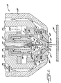
- the plasma arc torch 10 includes a nozzle assembly 12 and a tubular electrode 14 defining a longitudinal axis.
- the electrode 14 is preferably made of copper or a copper alloy, and it is composed of an upper tubular member 15 and a lower member or holder 16 which is threadedly connected to the upper member 15 .
- the holder 16 also is of tubular construction, and it includes a transverse end wall 18 which closes the front end of the holder 16 and which defines an outer front face.
- An emissive insert 20 is mounted in a cavity in the transverse end wall 18 and is disposed coaxially along the longitudinal axis of the torch.
- a relatively non-emissive sleeve 21 may be positioned coaxially about the insert 20 , as is conventional.
- the electrode 14 is mounted in a plasma arc torch body 22 , which has gas and liquid passageways 24 and 26 .
- the torch body 22 is surrounded by an outer insulated housing member 28 .
- a tube 30 is suspended within the central bore of the upper tubular member 15 for circulating a liquid medium such as water through the interior of the electrode structure.
- the tube 30 has an outer diameter which is smaller than the inner diameter of the bore to provide a space 32 for the water to flow upon discharge from the tube 30 .
- the water flows from a source (not shown) through the tube 30 , and back through the space 32 to an opening of the torch body and to a drain hose (not shown).
- the gas passageway 24 directs gas from a suitable source (not shown), through a conventional gas baffle 34 of any suitable high temperature ceramic material and into a gas plenum chamber 35 via several radial inlet holes 36 in the wall of the baffle 34 .
- the inlet holes 36 are arranged so as to cause the gas to enter the plenum chamber 35 in a swirling fashion as is well-known.
- the nozzle assembly 12 is mounted adjacent and below the discharge end wall 18 of the electrode, and it includes a nozzle base 40 and a lower nozzle member 42 .
- the nozzle base 40 is preferably formed from copper or a copper alloy, and it has a bore 44 therethrough that is aligned with the longitudinal axis and through which the plasma is ejected.
- the nozzle base 40 further includes an outer side which includes an outer frusto conical surface 46 which tapers toward and is coaxial with the longitudinal axis, and an exterior mounting shoulder 47 positioned longitudinally above the outer frusto conical surface 46 .
- the nozzle base 40 also includes a frusto conical interior surface 48 which tapers toward and is coaxial with the longitudinal axis.
- the bore 44 includes a first bore section 44a positioned closest to the electrode and a second bore section 44b defining the exit end of the bore and having a diameter slightly greater than the diameter of the first bore section 44a .
- the lower nozzle member 42 which also may be formed of copper or copper alloy, is mounted to the outer side of said nozzle base and includes a discharge opening 50 which is aligned with the longitudinal axis and positioned adjacent the bore 44 of said nozzle base.
- the lower nozzle member 42 further includes an inner frusto conical surface 52 spaced from and coaxial with the frusto conical surface 46 of the nozzle base so as to define a frusto conical passageway 53 therebetween.
- the lower nozzle member 42 also has an annular collar 54 which is closely fitted upon the mounting shoulder 47 of the nozzle base and so as to define an annular open chamber 56 between the nozzle base and the lower nozzle member which communicates with the frusto conical passageway 53 .
- the frusto conical passageway 53 defines an angle ⁇ with longitudinal axis which is less than about 30 degrees.
- a plurality of radial ducts 58 extend through the annular collar 54 of the lower nozzle member and communicate with the annular open chamber 56 .
- a water flow path is defined by the housing member 28 and which extends from the water delivery passageway 26 to the area surrounding the annular collar 54 , so that the water flows through the ducts 58 and thus into and through the frusto conical passageway 53 .
- the ducts 58 in the annular collar 54 may be tangentially inclined so as to impart a swirling movement to the water as it enters the frusto conical passageway 53 .
- the nozzle base 40 and the lower nozzle member 42 each define a lower terminal end, and the terminal end of the lower nozzle member is longitudinally below the terminal end of the base member a distance G of less than about .05 inches.
- the bore 44 of the base member has a diameter of between about .06 and .16 inches at the second bore portion 44b , and the discharge opening 50 in the lower nozzle member has a diameter of between about .10 and .22 inches.
- a ceramic insulator is secured onto the lower nozzle member 42 and extends substantially along the outer surface of the lower nozzle member.
- the ceramic insulator 60 helps prevent double arcing and insulates the lower nozzle member 42 from heat and plasma generated during torch operation.
- the ceramic insulator 60 may be glued onto the outer surface of the lower nozzle member 42 , and an O-ring 62 is positioned to create a seal between the ceramic insulator and the lower nozzle member.
- the outer housing member 28 of the torch has a lip 64 at its forward end, which engages an annular shoulder of the insulator 60 , thereby securing the lower nozzle member and nozzle base in position adjacent the electrode 14 .
- a power source (not shown) is connected to the torch electrode 14 in a series circuit relationship with a metal workpiece W , which typically is grounded.
- an electrical arc is generated between the emissive insert of the torch 10 and which extends through the bore 44 and the discharge opening 50 to a workpiece W located adjacent and below the lower nozzle member.
- the plasma arc is started in conventional manner by momentarily establishing a pilot arc between the electrode 14 and the nozzle assembly 12 .
- the arc then is transferred to the workpiece and is ejected through the arc restricting bore 44 and opening 50 .
- the vortical flow of gas which is formed between the electrode and the inner surface 48 of the nozzle base, surrounds the arc and forms a plasma jet, and the swirling vortex of water exiting from the passageway 53 envelopes the plasma jet as it passes through the opening.
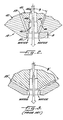
- FIGs 2 and 3 compare the present invention with the prior art construction.
- the frusto conical water passageway 53' of the prior art torches of the water injection type forms an angle ⁇ ' of about 45° with the longitudinal axis.
- Further information regarding a prior art torch of this type may be found in U.S. Patent Nos. 5,023,425 and 5,124,525, the disclosures of which are expressly incorporated herein by reference.
- the angle ⁇ is less than about 30°. As indicated above, it has been found that the smaller angle of the present invention has been found to permit the wall of the nozzle base 40 to be more thin, which promotes more efficient cooling of the nozzle assembly and without unduly cooling the plasma arc flow with the attendant reduction in its cutting effectiveness.
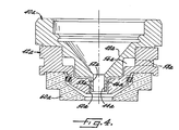
- Figure 4 illustrates a second embodiment of a nozzle assembly which embodies the present invention, with corresponding components being designated with the same numeral as in the first embodiment with a subscript "a".
- the second embodiment includes a nozzle base 40a , a lower nozzle member 42a , and a ceramic insulator 60a .
- the nozzle base 40a includes an outer side which includes an outer essentially cylindrical surface 46a which is coaxial with the longitudinal axis.
- the lower nozzle member 42a includes an inner essentially cylindrical surface 52a which is coextensive with the discharge opening 50a of the lower nozzle member.
- the surface 52a is also spaced from and coaxial with the outer surface 46a to define an essentially cylindrical passageway 53a therebetween, which communicates with the discharge opening 50a of the lower nozzle member.
- the water exits the passageway 53a in the form of an annular tube which is essentially parallel to the longitudinal axis.
- the passageway 53a may however be slightly frusto conical, so as to define an angle with the longitudinal axis of between about 0 and 10°.
- a 350 amp torch is provided, and the nozzle base 40 of the torch has a bore diameter of about .12 inches at its lower end.
- the discharge opening 50 of the lower nozzle member of the torch has a diameter of about .18 inches, and the longitudinal gap G between the terminal end of the lower nozzle member and the terminal end of the nozzle base is about .018 inches.
- the water passageway 53 defines an angle of about 0° with respect to the longitudinal axis, and the opposing surfaces 46, 52 are separated a distance of about .013 inches uniformly along the length of the passageway. In operation, the water flow rate is about 1/2 gallons per minute.
Description
- The present invention relates to a nozzle assembly adapted for use with a plasma arc torch having an improved water injection nozzle assembly.
- Plasma arc torches are commonly used for the working of metals, including cutting, welding, surface treatment, melting, and annealing. Such torches include an electrode which supports an arc which extends from the electrode to the workpiece in the transferred arc mode of operation. It is also conventional to surround the arc with a swirling vortex of gas which forms the plasma arc, and in some torch designs the gas and arc are enveloped with a swirling jet of water. The injection of water serves to constrict the plasma jet and thus increase its cutting ability. The water is also helpful in cooling the nozzle assembly and thus increasing the life of the assembly. Such a torch is known from US-A-5,124,525.
- While the benefits of the water injection system are recognized, it has been found that the injection of a sufficient amount of water to properly cool the nozzle assembly has the adverse effect of also cooling the plasma jet and thus reducing its cuttingeffectiveness. Thus, in existing torches, the dual objectives of achieving maximum cooling of the nozzle assembly, and proper restriction of the plasma jet without unduly cooling the jet, have not been realized.
- It is accordingly an object of the present invention to provide a plasma arc torch having an improved nozzle assembly which effectively provides maximum cooling of the nozzle assembly and proper constriction of the arc without unduly cooling the arc.
- The above and other objects and advantages of the present invention are achieved in the embodiment illustrated herein by the provision of a nozzle assembly for a plasma arc torch which comprises a nozzle base having a bore therethrough which defines a longitudinal axis and through which the plasma arc is adapted to be ejected. The nozzle base further includes an outer side which includes an annular outer surface which is coaxial with the longitudinal axis. A lower nozzle member is mounted to the outer side of the nozzle base and includes a discharge opening aligned with the longitudinal axis and positioned adjacent the bore of the nozzle base. Also, the lower nozzle member includes an annular inner surface which is spaced from and coaxial with the outer surface of the nozzle base so as to define an annular passageway therebetween. In accordance with the present invention, the annular passageway defines an angle with the longitudinal axis which is less than about 30 degrees. Such an assembly is claimed in claim 1, with embodiments claimed in claims 2-12.
- The torch as claimed in claim 13 includes the assembly as claimed in claims 1-12 further includes an electrode having a discharge end which is mounted in longitudinal alignment with the nozzle base and the lower nozzle member, and means for generating an electrical arc which extends from the electrode and through the bore and the discharge opening to a workpiece located adjacent and below the lower nozzle member. Means are also provided for generating a vortical flow of gas between the electrode and the nozzle base so as to create a plasma flow outwardly through the bore and the discharge opening and to the workpiece, and means are also provided for introducing a liquid, such as water, into the annular passageway of the nozzle assembly so that the water flows outwardly therefrom and envelopes the plasma flow as it passes through the discharge opening.
- In one conventional torch of this type, the water injection nozzle includes a frusto conical passageway, which forms a relatively large angle, typically at least about 45°, with respect to the longitudinal axis of the torch. In accordance with the present invention, it has been found that by significantly reducing this angle so as to be less than about 30°, the above-stated objects of the present invention can be achieved. In particular, the smaller angle has been found to permit the wall of the base member to be more thin, which in turn permits the assembly to be more efficiently cooled with less water, and in addition, there is less over cooling of the plasma arc flow.
- In one embodiment of the present invention, the annular outer surface of the nozzle base and the annular inner surface of the lower nozzle are both frusto conical, so as to define a frusto conical passageway with a uniform gap width along its length. In another embodiment, the outer and inner surfaces are essentially cylindrical, so as to define an essentially cylindrical passageway.
- Some of the objects and advantages of the present invention having been stated, others will appear as the description proceeds, when considered in conjunction with accompanying drawings, in which
- Figure 1 is a fragmentary sectioned side elevation view of the lower portion of a plasma arc torch which embodies the features of the present invention;
- Figure 2 is a fragmentary and enlarged sectional view of the nozzle assembly of the torch shown in Figure 1;
- Figure 3 is a view similar to Figure 2 but illustrating the prior art construction, and
- Figure 4 is a sectional view of a second embodiment of the nozzle assembly of the present invention.
-
- Referring now to the drawings, and more particularly to Figure 1, there is disclosed a first embodiment plasma arc torch 10 which includes the features of the present invention. The plasma arc torch 10 includes a
nozzle assembly 12 and a tubular electrode 14 defining a longitudinal axis. The electrode 14 is preferably made of copper or a copper alloy, and it is composed of an uppertubular member 15 and a lower member or holder 16 which is threadedly connected to theupper member 15. The holder 16 also is of tubular construction, and it includes a transverse end wall 18 which closes the front end of the holder 16 and which defines an outer front face. An emissive insert 20 is mounted in a cavity in the transverse end wall 18 and is disposed coaxially along the longitudinal axis of the torch. A relatively non-emissive sleeve 21 may be positioned coaxially about the insert 20, as is conventional. - In the illustrated embodiment, as shown in Figure 1, the electrode 14 is mounted in a plasma arc torch body 22, which has gas and
liquid passageways 24 and 26. The torch body 22 is surrounded by an outer insulated housing member 28. - A
tube 30 is suspended within the central bore of the uppertubular member 15 for circulating a liquid medium such as water through the interior of the electrode structure. Thetube 30 has an outer diameter which is smaller than the inner diameter of the bore to provide a space 32 for the water to flow upon discharge from thetube 30. The water flows from a source (not shown) through thetube 30, and back through the space 32 to an opening of the torch body and to a drain hose (not shown). - The
gas passageway 24 directs gas from a suitable source (not shown), through a conventional gas baffle 34 of any suitable high temperature ceramic material and into a gas plenum chamber 35 via several radial inlet holes 36 in the wall of the baffle 34. The inlet holes 36 are arranged so as to cause the gas to enter the plenum chamber 35 in a swirling fashion as is well-known. - The
nozzle assembly 12 is mounted adjacent and below the discharge end wall 18 of the electrode, and it includes a nozzle base 40 and a lower nozzle member 42. The nozzle base 40 is preferably formed from copper or a copper alloy, and it has a bore 44 therethrough that is aligned with the longitudinal axis and through which the plasma is ejected. The nozzle base 40 further includes an outer side which includes an outer frusto conical surface 46 which tapers toward and is coaxial with the longitudinal axis, and an exterior mounting shoulder 47 positioned longitudinally above the outer frusto conical surface 46. The nozzle base 40 also includes a frusto conical interior surface 48 which tapers toward and is coaxial with the longitudinal axis. In the illustrated embodiment, the bore 44 includes a first bore section 44a positioned closest to the electrode and asecond bore section 44b defining the exit end of the bore and having a diameter slightly greater than the diameter of the first bore section 44a. - The lower nozzle member 42, which also may be formed of copper or copper alloy, is mounted to the outer side of said nozzle base and includes a
discharge opening 50 which is aligned with the longitudinal axis and positioned adjacent the bore 44 of said nozzle base. The lower nozzle member 42 further includes an inner frusto conical surface 52 spaced from and coaxial with the frusto conical surface 46 of the nozzle base so as to define a frusto conical passageway 53 therebetween. The lower nozzle member 42 also has an annular collar 54 which is closely fitted upon the mounting shoulder 47 of the nozzle base and so as to define an annular open chamber 56 between the nozzle base and the lower nozzle member which communicates with the frusto conical passageway 53. Also, in accordance with the present invention, the frusto conical passageway 53 defines an angle β with longitudinal axis which is less than about 30 degrees. - A plurality of radial ducts 58 extend through the annular collar 54 of the lower nozzle member and communicate with the annular open chamber 56. A water flow path is defined by the housing member 28 and which extends from the water delivery passageway 26 to the area surrounding the annular collar 54, so that the water flows through the ducts 58 and thus into and through the frusto conical passageway 53. The ducts 58 in the annular collar 54 may be tangentially inclined so as to impart a swirling movement to the water as it enters the frusto conical passageway 53.
- Also in the case of the present invention, the nozzle base 40 and the lower nozzle member 42 each define a lower terminal end, and the terminal end of the lower nozzle member is longitudinally below the terminal end of the base member a distance G of less than about .05 inches. The bore 44 of the base member has a diameter of between about .06 and .16 inches at the
second bore portion 44b, and the discharge opening 50 in the lower nozzle member has a diameter of between about .10 and .22 inches. - A ceramic insulator, indicated generally at 60, is secured onto the lower nozzle member 42 and extends substantially along the outer surface of the lower nozzle member. The ceramic insulator 60 helps prevent double arcing and insulates the lower nozzle member 42 from heat and plasma generated during torch operation. The ceramic insulator 60 may be glued onto the outer surface of the lower nozzle member 42, and an O-ring 62 is positioned to create a seal between the ceramic insulator and the lower nozzle member.
- The outer housing member 28 of the torch has a lip 64 at its forward end, which engages an annular shoulder of the insulator 60, thereby securing the lower nozzle member and nozzle base in position adjacent the electrode 14.
- A power source (not shown) is connected to the torch electrode 14 in a series circuit relationship with a metal workpiece W, which typically is grounded. In operation, an electrical arc is generated between the emissive insert of the torch 10 and which extends through the bore 44 and the discharge opening 50 to a workpiece W located adjacent and below the lower nozzle member. The plasma arc is started in conventional manner by momentarily establishing a pilot arc between the electrode 14 and the
nozzle assembly 12. The arc then is transferred to the workpiece and is ejected through the arc restricting bore 44 andopening 50. The vortical flow of gas which is formed between the electrode and the inner surface 48 of the nozzle base, surrounds the arc and forms a plasma jet, and the swirling vortex of water exiting from the passageway 53 envelopes the plasma jet as it passes through the opening. - Figures 2 and 3 compare the present invention with the prior art construction. As illustrated in Figure 3, the frusto conical water passageway 53' of the prior art torches of the water injection type forms an angle β' of about 45° with the longitudinal axis. Further information regarding a prior art torch of this type may be found in U.S. Patent Nos. 5,023,425 and 5,124,525, the disclosures of which are expressly incorporated herein by reference.
- With the present invention, and as illustrated in Figure 2, the angle β is less than about 30°. As indicated above, it has been found that the smaller angle of the present invention has been found to permit the wall of the nozzle base 40 to be more thin, which promotes more efficient cooling of the nozzle assembly and without unduly cooling the plasma arc flow with the attendant reduction in its cutting effectiveness.
- Figure 4 illustrates a second embodiment of a nozzle assembly which embodies the present invention, with corresponding components being designated with the same numeral as in the first embodiment with a subscript "a". In particular, the second embodiment includes a
nozzle base 40a, a lower nozzle member 42a, and aceramic insulator 60a. Thenozzle base 40a includes an outer side which includes an outer essentiallycylindrical surface 46a which is coaxial with the longitudinal axis. The lower nozzle member 42a includes an inner essentiallycylindrical surface 52a which is coextensive with thedischarge opening 50a of the lower nozzle member. Thesurface 52a is also spaced from and coaxial with theouter surface 46a to define an essentially cylindrical passageway 53a therebetween, which communicates with thedischarge opening 50a of the lower nozzle member. Thus in this embodiment, the water exits the passageway 53a in the form of an annular tube which is essentially parallel to the longitudinal axis. The passageway 53a may however be slightly frusto conical, so as to define an angle with the longitudinal axis of between about 0 and 10°. - In one specific example of the present invention, a 350 amp torch is provided, and the nozzle base 40 of the torch has a bore diameter of about .12 inches at its lower end. The
discharge opening 50 of the lower nozzle member of the torch has a diameter of about .18 inches, and the longitudinal gap G between the terminal end of the lower nozzle member and the terminal end of the nozzle base is about .018 inches. The water passageway 53 defines an angle of about 0° with respect to the longitudinal axis, and the opposing surfaces 46, 52 are separated a distance of about .013 inches uniformly along the length of the passageway. In operation, the water flow rate is about 1/2 gallons per minute. - In the drawings and specification, there has been set forth a preferred embodiment of the invention, and although specific terms are employed, they are used in a generic and descriptive sense only and not for purposes of limitation.
Claims (13)
- A nozzle assembly adapted for use with a plasma arc torch and comprising:a nozzle base (40) having a bore (44) therethrough which defines a longitudinal axis and through which plasma is adapted to be ejected, said nozzle base (40) further including an outer side which includes an annular outer surface (46) which is coaxial with said longitudinal axis, anda lower nozzle member (42) mounted to said outer side of said nozzle base (40) and including a discharge opening (50) aligned with the longitudinal axis and positioned adjacent said bore (44) of said nozzle base (40), and further including an annular inner surface (52) spaced from and coaxial with said outer surface (46) of said nozzle base (40) so as to define an annular passageway (53) therebetween which communicates with said discharge opening characterised in that said passageway (53) defines an angle with said longitudinal axis which is less than about 30 degrees.
- A nozzle assembly as claimed in Claim 1, wherein said annular passageway (53) is frusto conical and has a substantially uniform gap width along its length.
- A nozzle assembly as claimed in Claim 1, wherein said annular passageway (53) is essentially cylindrical.
- A nozzle assembly as claimed in any preceding claim, wherein said nozzle base (40) and said lower nozzle member (42) each define a lower terminal end, and wherein the terminal end of said lower nozzle member (42) is longitudinally below the terminal end of said nozzle base (40).
- A nozzle assembly as claimed in claim 4, wherein said distance is less than about 1.27 mm (0.05 inches).
- A nozzle assembly as claimed in any preceding claim, wherein said bore of said nozzle base (40) has a diameter which is less than the diameter of the discharge opening in said lower nozzle member (42).
- A nozzle assembly as claimed in Claim 6, wherein said bore of said nozzle base (40) has a diameter of between about 1.524 mm and 4.064 mm (0.06 and 0.16 inches), and wherein the discharge opening in said lower nozzle member (42) has a diameter of between about 2.54 mm and 5.588 mm (0.10 and 0.22 inches).
- A nozzle assembly as claimed in any preceding Claim, further comprising a ceramic insulator (60) secured to the side of the lower nozzle member (42) which is opposite said inner surface thereof.
- A nozzle assembly as claimed in any preceding Claim, wherein said nozzle base (40) includes a frusto conical interior surface (48) which tapers toward and is coaxial with said longitudinal axis.
- A nozzle assembly as claimed in any preceding Claim, wherein said outer side of said nozzle base (40) further includes an exterior annular mounting shoulder (47) positioned longitudinally above the outer surface (46) thereof, and wherein said lower nozzle member (42) includes an annular collar (54) which is closely fitted upon said mounting shoulder (47) and so as to define an annular open chamber (56) between said nozzle base (40) and said lower nozzle member (42) which communicates with said passageway (53).
- A nozzle assembly as claimed in Claim 10, further including at least one radial duct (58) extending through said annular collar (54) and communicating with said annular open chamber (56).
- A nozzle assembly as claimed in Claim 1, wherein said annular passageway (53) defines an angle with said longitudinal axis of between about 0 and 10°.
- A plasma arc torch comprising a nozzle assembly as claimed in any preceding claim, an electrode (14) fitted within the nozzle base (40) and having a discharge end adjacent the bore (44) of said nozzle base (40), the longitudinal axis of said electrode (14) being aligned with said bore (44)means for generating an electrical arc extending from the electrode (14) and through the bore and the discharge opening (50) to a workpiece located adjacent and below the lower nozzle member (42),means (24,36,35) for generating a vortical flow of gas between the electrode (14) and the nozzle base (40) so as to create a plasma flow outwardly through the bore and the discharge opening (50) and to the workpiece, andmeans (26) for introducing a liquid into said passageway (53) so that the liquid flows outwardly therefrom and envelops the plasma flow as it passes through the discharge opening (50).
Applications Claiming Priority (2)
| Application Number | Priority Date | Filing Date | Title |
|---|---|---|---|
| US464241 | 1995-06-05 | ||
| US08/464,241 US5660743A (en) | 1995-06-05 | 1995-06-05 | Plasma arc torch having water injection nozzle assembly |
Publications (2)
| Publication Number | Publication Date |
|---|---|
| EP0748149A1 EP0748149A1 (en) | 1996-12-11 |
| EP0748149B1 true EP0748149B1 (en) | 1999-08-11 |
Family
ID=23843111
Family Applications (1)
| Application Number | Title | Priority Date | Filing Date |
|---|---|---|---|
| EP96302863A Expired - Lifetime EP0748149B1 (en) | 1995-06-05 | 1996-04-24 | Plasma arc torch having water injection nozzle assembly |
Country Status (6)
| Country | Link |
|---|---|
| US (1) | US5660743A (en) |
| EP (1) | EP0748149B1 (en) |
| JP (1) | JP2849573B2 (en) |
| KR (1) | KR100199782B1 (en) |
| CA (1) | CA2174019C (en) |
| DE (1) | DE69603673T2 (en) |
Cited By (9)
| Publication number | Priority date | Publication date | Assignee | Title |
|---|---|---|---|---|
| US7928338B2 (en) | 2007-02-02 | 2011-04-19 | Plasma Surgical Investments Ltd. | Plasma spraying device and method |
| US8030849B2 (en) | 2007-08-06 | 2011-10-04 | Plasma Surgical Investments Limited | Pulsed plasma device and method for generating pulsed plasma |
| CN101204123B (en) * | 2005-04-19 | 2011-10-05 | 海别得公司 | Plasma arc torch providing angular shield flow injection |
| US8105325B2 (en) | 2005-07-08 | 2012-01-31 | Plasma Surgical Investments Limited | Plasma-generating device, plasma surgical device, use of a plasma-generating device and method of generating a plasma |
| US8109928B2 (en) | 2005-07-08 | 2012-02-07 | Plasma Surgical Investments Limited | Plasma-generating device, plasma surgical device and use of plasma surgical device |
| US8613742B2 (en) | 2010-01-29 | 2013-12-24 | Plasma Surgical Investments Limited | Methods of sealing vessels using plasma |
| US8735766B2 (en) | 2007-08-06 | 2014-05-27 | Plasma Surgical Investments Limited | Cathode assembly and method for pulsed plasma generation |
| US9089319B2 (en) | 2010-07-22 | 2015-07-28 | Plasma Surgical Investments Limited | Volumetrically oscillating plasma flows |
| US11856684B2 (en) * | 2017-09-22 | 2023-12-26 | Kjellberg-Stiftung | Nozzle for a plasma arc torch head, laser cutting head and plasma laser cutting head, assemblies, plasma arc torch head and plasma arc torch comprising same, laser cutting head comprising same, and plasma laser cutting head comprising same |
Families Citing this family (51)
| Publication number | Priority date | Publication date | Assignee | Title |
|---|---|---|---|---|
| WO1998002270A1 (en) * | 1996-07-11 | 1998-01-22 | Apunevich Aleksandr I | Method for the plasmic arc-welding of metals |
| KR19980025483A (en) * | 1996-10-01 | 1998-07-15 | 이대원 | Steam Plasma Tochigi |
| RU2103129C1 (en) * | 1997-03-03 | 1998-01-27 | Александр Иванович Апуневич | Method of plasma-arc welding of metals |
| DE19716235C2 (en) * | 1997-04-18 | 2001-11-29 | Deutsch Zentr Luft & Raumfahrt | Plasma torch with a fluid-cooled anode |
| WO1999012693A1 (en) * | 1997-09-10 | 1999-03-18 | The Esab Group, Inc. | Electrode with emissive element having conductive portions |
| US5906758A (en) * | 1997-09-30 | 1999-05-25 | The Esab Group, Inc. | Plasma arc torch |
| US6215090B1 (en) * | 1998-03-06 | 2001-04-10 | The Esab Group, Inc. | Plasma arc torch |
| US6207923B1 (en) * | 1998-11-05 | 2001-03-27 | Hypertherm, Inc. | Plasma arc torch tip providing a substantially columnar shield flow |
| US6156995A (en) * | 1998-12-02 | 2000-12-05 | The Esab Group, Inc. | Water-injection nozzle assembly with insulated front end |
| US6096992A (en) * | 1999-01-29 | 2000-08-01 | The Esab Group, Inc. | Low current water injection nozzle and associated method |
| US6498316B1 (en) | 1999-10-25 | 2002-12-24 | Thermal Dynamics Corporation | Plasma torch and method for underwater cutting |
| US20040011378A1 (en) * | 2001-08-23 | 2004-01-22 | Jackson David P | Surface cleaning and modification processes, methods and apparatus using physicochemically modified dense fluid sprays |
| US7622693B2 (en) | 2001-07-16 | 2009-11-24 | Foret Plasma Labs, Llc | Plasma whirl reactor apparatus and methods of use |
| US8764978B2 (en) | 2001-07-16 | 2014-07-01 | Foret Plasma Labs, Llc | System for treating a substance with wave energy from an electrical arc and a second source |
| CN1662337B (en) | 2002-04-19 | 2010-12-08 | 美商热动力公司 | Plasma arc torch tip, plasma arc torch and operation method thereof |
| US20080116179A1 (en) * | 2003-04-11 | 2008-05-22 | Hypertherm, Inc. | Method and apparatus for alignment of components of a plasma arc torch |
| US6946617B2 (en) * | 2003-04-11 | 2005-09-20 | Hypertherm, Inc. | Method and apparatus for alignment of components of a plasma arc torch |
| SE529053C2 (en) * | 2005-07-08 | 2007-04-17 | Plasma Surgical Invest Ltd | Plasma generating device, plasma surgical device and use of a plasma surgical device |
| KR100807806B1 (en) * | 2006-04-04 | 2008-02-27 | 제주대학교 산학협력단 | DC arc plasmatron and the method using the same |
| US7737383B2 (en) * | 2006-08-25 | 2010-06-15 | Thermal Dynamics Corporation | Contoured shield orifice for a plasma arc torch |
| US8772667B2 (en) * | 2007-02-09 | 2014-07-08 | Hypertherm, Inc. | Plasma arch torch cutting component with optimized water cooling |
| US8829385B2 (en) * | 2007-02-09 | 2014-09-09 | Hypertherm, Inc. | Plasma arc torch cutting component with optimized water cooling |
| US7935909B2 (en) * | 2007-09-04 | 2011-05-03 | Thermal Dynamics Corporation | Hybrid shield device for a plasma arc torch |
| TWI352368B (en) * | 2007-09-21 | 2011-11-11 | Ind Tech Res Inst | Plasma head and plasma-discharging device using th |
| US9185787B2 (en) | 2007-10-16 | 2015-11-10 | Foret Plasma Labs, Llc | High temperature electrolysis glow discharge device |
| US10267106B2 (en) | 2007-10-16 | 2019-04-23 | Foret Plasma Labs, Llc | System, method and apparatus for treating mining byproducts |
| US8278810B2 (en) | 2007-10-16 | 2012-10-02 | Foret Plasma Labs, Llc | Solid oxide high temperature electrolysis glow discharge cell |
| US9051820B2 (en) | 2007-10-16 | 2015-06-09 | Foret Plasma Labs, Llc | System, method and apparatus for creating an electrical glow discharge |
| US11806686B2 (en) | 2007-10-16 | 2023-11-07 | Foret Plasma Labs, Llc | System, method and apparatus for creating an electrical glow discharge |
| US9230777B2 (en) | 2007-10-16 | 2016-01-05 | Foret Plasma Labs, Llc | Water/wastewater recycle and reuse with plasma, activated carbon and energy system |
| US9761413B2 (en) | 2007-10-16 | 2017-09-12 | Foret Plasma Labs, Llc | High temperature electrolysis glow discharge device |
| US9516736B2 (en) | 2007-10-16 | 2016-12-06 | Foret Plasma Labs, Llc | System, method and apparatus for recovering mining fluids from mining byproducts |
| US8074439B2 (en) | 2008-02-12 | 2011-12-13 | Foret Plasma Labs, Llc | System, method and apparatus for lean combustion with plasma from an electrical arc |
| US8810122B2 (en) | 2007-10-16 | 2014-08-19 | Foret Plasma Labs, Llc | Plasma arc torch having multiple operating modes |
| US9445488B2 (en) | 2007-10-16 | 2016-09-13 | Foret Plasma Labs, Llc | Plasma whirl reactor apparatus and methods of use |
| US9560731B2 (en) | 2007-10-16 | 2017-01-31 | Foret Plasma Labs, Llc | System, method and apparatus for an inductively coupled plasma Arc Whirl filter press |
| US8742284B2 (en) * | 2007-11-06 | 2014-06-03 | Institute Of Nuclear Energy Research, Atomic Energy Council | Steam plasma torch |
| US8904749B2 (en) | 2008-02-12 | 2014-12-09 | Foret Plasma Labs, Llc | Inductively coupled plasma arc device |
| US10244614B2 (en) | 2008-02-12 | 2019-03-26 | Foret Plasma Labs, Llc | System, method and apparatus for plasma arc welding ceramics and sapphire |
| DE102009006132C5 (en) * | 2008-10-09 | 2015-06-03 | Kjellberg Finsterwalde Plasma Und Maschinen Gmbh | Nozzle for a liquid-cooled plasma torch, nozzle cap for a liquid-cooled plasma torch and plasma torch head with the same |
| GB201106314D0 (en) * | 2011-04-14 | 2011-06-01 | Edwards Ltd | Plasma torch |
| WO2014093560A1 (en) | 2012-12-11 | 2014-06-19 | Foret Plasma Labs, Llc | High temperature countercurrent vortex reactor system, method and apparatus |
| US9699879B2 (en) | 2013-03-12 | 2017-07-04 | Foret Plasma Labs, Llc | Apparatus and method for sintering proppants |
| US9144148B2 (en) | 2013-07-25 | 2015-09-22 | Hypertherm, Inc. | Devices for gas cooling plasma arc torches and related systems and methods |
| US9686848B2 (en) * | 2014-09-25 | 2017-06-20 | Lincoln Global, Inc. | Plasma cutting torch, nozzle and shield cap |
| CN107113957B (en) | 2015-06-08 | 2021-03-12 | 海别得公司 | Cooled plasma torch nozzles and related systems and methods |
| USD861758S1 (en) | 2017-07-10 | 2019-10-01 | Lincoln Global, Inc. | Vented plasma cutting electrode |
| US10589373B2 (en) | 2017-07-10 | 2020-03-17 | Lincoln Global, Inc. | Vented plasma cutting electrode and torch using the same |
| TWI701976B (en) * | 2018-08-15 | 2020-08-11 | 東服企業股份有限公司 | Water molecule supply device for plasma torch excitation device |
| EP4205515A2 (en) | 2020-08-28 | 2023-07-05 | Plasma Surgical Investments Limited | Systems, methods, and devices for generating predominantly radially expanded plasma flow |
| BR102021004727A2 (en) * | 2021-03-12 | 2022-09-20 | Paulo Roberto Paladini | HYDROGEN AND OXYGEN BURNING SYSTEM BY ELECTRICAL INDUCTION OF PLASMA IN PRESSURE VESSEL |
Family Cites Families (12)
| Publication number | Priority date | Publication date | Assignee | Title |
|---|---|---|---|---|
| US3534388A (en) * | 1968-03-13 | 1970-10-13 | Hitachi Ltd | Plasma jet cutting process |
| US3833787A (en) * | 1972-06-12 | 1974-09-03 | Hypotherm Inc | Plasma jet cutting torch having reduced noise generating characteristics |
| JPS5546266A (en) * | 1978-09-28 | 1980-03-31 | Daido Steel Co Ltd | Plasma torch |
| US4311897A (en) * | 1979-08-28 | 1982-01-19 | Union Carbide Corporation | Plasma arc torch and nozzle assembly |
| DE3024339A1 (en) * | 1980-07-02 | 1982-01-21 | NPK za Kontrolno-Zavaračni Raboti, Sofija | PLASMATRON FOR METAL WORKING IN AIR AND UNDERWATER |
| US4369919A (en) * | 1980-10-31 | 1983-01-25 | Npk Za Kontrolno Zavarachni Raboti | Plasma torch for processing metals in the air and under water |
| JPS6317030A (en) * | 1986-07-09 | 1988-01-25 | Hitachi Ltd | Molding equipment of bonded lens |
| NL8800767A (en) * | 1988-03-28 | 1989-10-16 | Philips Nv | PLASMA torches. |
| US5120930A (en) * | 1988-06-07 | 1992-06-09 | Hypertherm, Inc. | Plasma arc torch with improved nozzle shield and step flow |
| US5023425A (en) * | 1990-01-17 | 1991-06-11 | Esab Welding Products, Inc. | Electrode for plasma arc torch and method of fabricating same |
| DE4022111A1 (en) * | 1990-07-11 | 1992-01-23 | Krupp Gmbh | PLASMA TORCH FOR TRANSFERED ARC |
| US5124525A (en) * | 1991-08-27 | 1992-06-23 | Esab Welding Products, Inc. | Plasma arc torch having improved nozzle assembly |
-
1995
- 1995-06-05 US US08/464,241 patent/US5660743A/en not_active Expired - Lifetime
-
1996
- 1996-04-12 CA CA002174019A patent/CA2174019C/en not_active Expired - Fee Related
- 1996-04-24 DE DE69603673T patent/DE69603673T2/en not_active Expired - Fee Related
- 1996-04-24 EP EP96302863A patent/EP0748149B1/en not_active Expired - Lifetime
- 1996-05-10 KR KR1019960015313A patent/KR100199782B1/en not_active IP Right Cessation
- 1996-06-04 JP JP8141295A patent/JP2849573B2/en not_active Expired - Fee Related
Cited By (11)
| Publication number | Priority date | Publication date | Assignee | Title |
|---|---|---|---|---|
| CN101204123B (en) * | 2005-04-19 | 2011-10-05 | 海别得公司 | Plasma arc torch providing angular shield flow injection |
| US8105325B2 (en) | 2005-07-08 | 2012-01-31 | Plasma Surgical Investments Limited | Plasma-generating device, plasma surgical device, use of a plasma-generating device and method of generating a plasma |
| US8109928B2 (en) | 2005-07-08 | 2012-02-07 | Plasma Surgical Investments Limited | Plasma-generating device, plasma surgical device and use of plasma surgical device |
| US8337494B2 (en) | 2005-07-08 | 2012-12-25 | Plasma Surgical Investments Limited | Plasma-generating device having a plasma chamber |
| US8465487B2 (en) | 2005-07-08 | 2013-06-18 | Plasma Surgical Investments Limited | Plasma-generating device having a throttling portion |
| US7928338B2 (en) | 2007-02-02 | 2011-04-19 | Plasma Surgical Investments Ltd. | Plasma spraying device and method |
| US8030849B2 (en) | 2007-08-06 | 2011-10-04 | Plasma Surgical Investments Limited | Pulsed plasma device and method for generating pulsed plasma |
| US8735766B2 (en) | 2007-08-06 | 2014-05-27 | Plasma Surgical Investments Limited | Cathode assembly and method for pulsed plasma generation |
| US8613742B2 (en) | 2010-01-29 | 2013-12-24 | Plasma Surgical Investments Limited | Methods of sealing vessels using plasma |
| US9089319B2 (en) | 2010-07-22 | 2015-07-28 | Plasma Surgical Investments Limited | Volumetrically oscillating plasma flows |
| US11856684B2 (en) * | 2017-09-22 | 2023-12-26 | Kjellberg-Stiftung | Nozzle for a plasma arc torch head, laser cutting head and plasma laser cutting head, assemblies, plasma arc torch head and plasma arc torch comprising same, laser cutting head comprising same, and plasma laser cutting head comprising same |
Also Published As
| Publication number | Publication date |
|---|---|
| KR100199782B1 (en) | 1999-06-15 |
| JPH08339894A (en) | 1996-12-24 |
| CA2174019A1 (en) | 1996-12-06 |
| DE69603673D1 (en) | 1999-09-16 |
| KR970000423A (en) | 1997-01-21 |
| EP0748149A1 (en) | 1996-12-11 |
| US5660743A (en) | 1997-08-26 |
| JP2849573B2 (en) | 1999-01-20 |
| CA2174019C (en) | 1998-10-27 |
| DE69603673T2 (en) | 2000-03-09 |
Similar Documents
| Publication | Publication Date | Title |
|---|---|---|
| EP0748149B1 (en) | Plasma arc torch having water injection nozzle assembly | |
| EP0444344B1 (en) | Plasma arc starting process | |
| CA2024861C (en) | Plasma arc cutting torch having extended lower nozzle member | |
| US5124525A (en) | Plasma arc torch having improved nozzle assembly | |
| US5451739A (en) | Electrode for plasma arc torch having channels to extend service life | |
| US7375302B2 (en) | Plasma arc torch having an electrode with internal passages | |
| US4311897A (en) | Plasma arc torch and nozzle assembly | |
| EP0437915B2 (en) | Electrode for plasma ARC torch | |
| US5013885A (en) | Plasma arc torch having extended nozzle of substantially hourglass | |
| US5414237A (en) | Plasma arc torch with integral gas exchange | |
| JP2519387B2 (en) | Plasma torch nozzle body and plasma torch assembly | |
| US5310988A (en) | Electrode for high current density plasma arc torch | |
| US5194715A (en) | Plasma arc torch used in underwater cutting | |
| JPH0450865B2 (en) | ||
| US6498316B1 (en) | Plasma torch and method for underwater cutting | |
| US6096992A (en) | Low current water injection nozzle and associated method | |
| US5362938A (en) | Plasma arc welding torch having means for "vortexing" plasma gas exiting the welding torch | |
| Rybicki et al. | Plasma arc welding torch having means for vortexing plasma gas exiting the welding torch |
Legal Events
| Date | Code | Title | Description |
|---|---|---|---|
| PUAI | Public reference made under article 153(3) epc to a published international application that has entered the european phase |
Free format text: ORIGINAL CODE: 0009012 |
|
| AK | Designated contracting states |
Kind code of ref document: A1 Designated state(s): DE FR GB NL |
|
| 17P | Request for examination filed |
Effective date: 19961202 |
|
| 17Q | First examination report despatched |
Effective date: 19971107 |
|
| GRAG | Despatch of communication of intention to grant |
Free format text: ORIGINAL CODE: EPIDOS AGRA |
|
| GRAG | Despatch of communication of intention to grant |
Free format text: ORIGINAL CODE: EPIDOS AGRA |
|
| GRAH | Despatch of communication of intention to grant a patent |
Free format text: ORIGINAL CODE: EPIDOS IGRA |
|
| GRAH | Despatch of communication of intention to grant a patent |
Free format text: ORIGINAL CODE: EPIDOS IGRA |
|
| GRAA | (expected) grant |
Free format text: ORIGINAL CODE: 0009210 |
|
| AK | Designated contracting states |
Kind code of ref document: B1 Designated state(s): DE FR GB NL |
|
| REF | Corresponds to: |
Ref document number: 69603673 Country of ref document: DE Date of ref document: 19990916 |
|
| ET | Fr: translation filed | ||
| PLBE | No opposition filed within time limit |
Free format text: ORIGINAL CODE: 0009261 |
|
| STAA | Information on the status of an ep patent application or granted ep patent |
Free format text: STATUS: NO OPPOSITION FILED WITHIN TIME LIMIT |
|
| 26N | No opposition filed | ||
| PGFP | Annual fee paid to national office [announced via postgrant information from national office to epo] |
Ref country code: FR Payment date: 20010330 Year of fee payment: 6 |
|
| PGFP | Annual fee paid to national office [announced via postgrant information from national office to epo] |
Ref country code: DE Payment date: 20010402 Year of fee payment: 6 |
|
| PGFP | Annual fee paid to national office [announced via postgrant information from national office to epo] |
Ref country code: GB Payment date: 20010403 Year of fee payment: 6 |
|
| PGFP | Annual fee paid to national office [announced via postgrant information from national office to epo] |
Ref country code: NL Payment date: 20010412 Year of fee payment: 6 |
|
| REG | Reference to a national code |
Ref country code: GB Ref legal event code: IF02 |
|
| PG25 | Lapsed in a contracting state [announced via postgrant information from national office to epo] |
Ref country code: GB Free format text: LAPSE BECAUSE OF NON-PAYMENT OF DUE FEES Effective date: 20020424 |
|
| PG25 | Lapsed in a contracting state [announced via postgrant information from national office to epo] |
Ref country code: NL Free format text: LAPSE BECAUSE OF NON-PAYMENT OF DUE FEES Effective date: 20021101 Ref country code: DE Free format text: LAPSE BECAUSE OF NON-PAYMENT OF DUE FEES Effective date: 20021101 |
|
| GBPC | Gb: european patent ceased through non-payment of renewal fee |
Effective date: 20020424 |
|
| PG25 | Lapsed in a contracting state [announced via postgrant information from national office to epo] |
Ref country code: FR Free format text: LAPSE BECAUSE OF NON-PAYMENT OF DUE FEES Effective date: 20021231 |
|
| NLV4 | Nl: lapsed or anulled due to non-payment of the annual fee |
Effective date: 20021101 |
|
| REG | Reference to a national code |
Ref country code: FR Ref legal event code: ST |