EP0747759A2 - Photographic elements which achieve colorimetrically accurate recording - Google Patents
Photographic elements which achieve colorimetrically accurate recording Download PDFInfo
- Publication number
- EP0747759A2 EP0747759A2 EP96420182A EP96420182A EP0747759A2 EP 0747759 A2 EP0747759 A2 EP 0747759A2 EP 96420182 A EP96420182 A EP 96420182A EP 96420182 A EP96420182 A EP 96420182A EP 0747759 A2 EP0747759 A2 EP 0747759A2
- Authority
- EP
- European Patent Office
- Prior art keywords
- image
- photographic
- exposure
- color
- photographic element
- Prior art date
- Legal status (The legal status is an assumption and is not a legal conclusion. Google has not performed a legal analysis and makes no representation as to the accuracy of the status listed.)
- Granted
Links
- 230000003595 spectral effect Effects 0.000 claims abstract description 145
- 239000000839 emulsion Substances 0.000 claims abstract description 143
- 230000035945 sensitivity Effects 0.000 claims abstract description 113
- 229910052709 silver Inorganic materials 0.000 claims abstract description 86
- 239000004332 silver Substances 0.000 claims abstract description 86
- -1 silver halide Chemical class 0.000 claims abstract description 71
- 230000006870 function Effects 0.000 claims abstract description 35
- 239000011159 matrix material Substances 0.000 claims abstract description 29
- 239000003086 colorant Substances 0.000 claims abstract description 28
- 238000012360 testing method Methods 0.000 claims abstract description 17
- 239000000975 dye Substances 0.000 claims description 222
- 238000012545 processing Methods 0.000 claims description 48
- 238000010521 absorption reaction Methods 0.000 claims description 17
- 238000001228 spectrum Methods 0.000 claims description 17
- 230000009467 reduction Effects 0.000 claims description 3
- 239000002243 precursor Substances 0.000 claims 1
- 239000010410 layer Substances 0.000 description 130
- 238000000034 method Methods 0.000 description 54
- 238000003384 imaging method Methods 0.000 description 40
- 230000001235 sensitizing effect Effects 0.000 description 37
- BQCADISMDOOEFD-UHFFFAOYSA-N Silver Chemical compound [Ag] BQCADISMDOOEFD-UHFFFAOYSA-N 0.000 description 33
- 230000033458 reproduction Effects 0.000 description 29
- 230000008569 process Effects 0.000 description 27
- ZUNKMNLKJXRCDM-UHFFFAOYSA-N silver bromoiodide Chemical compound [Ag].IBr ZUNKMNLKJXRCDM-UHFFFAOYSA-N 0.000 description 26
- 108010010803 Gelatin Proteins 0.000 description 25
- 229920000159 gelatin Polymers 0.000 description 25
- 239000008273 gelatin Substances 0.000 description 25
- 235000019322 gelatine Nutrition 0.000 description 25
- 235000011852 gelatine desserts Nutrition 0.000 description 25
- 238000011161 development Methods 0.000 description 23
- QGKMIGUHVLGJBR-UHFFFAOYSA-M (4z)-1-(3-methylbutyl)-4-[[1-(3-methylbutyl)quinolin-1-ium-4-yl]methylidene]quinoline;iodide Chemical compound [I-].C12=CC=CC=C2N(CCC(C)C)C=CC1=CC1=CC=[N+](CCC(C)C)C2=CC=CC=C12 QGKMIGUHVLGJBR-UHFFFAOYSA-M 0.000 description 22
- 230000000875 corresponding effect Effects 0.000 description 16
- 230000009102 absorption Effects 0.000 description 15
- 239000011229 interlayer Substances 0.000 description 15
- 238000011160 research Methods 0.000 description 14
- IOJUPLGTWVMSFF-UHFFFAOYSA-N benzothiazole Chemical compound C1=CC=C2SC=NC2=C1 IOJUPLGTWVMSFF-UHFFFAOYSA-N 0.000 description 12
- DZVCFNFOPIZQKX-LTHRDKTGSA-M merocyanine Chemical compound [Na+].O=C1N(CCCC)C(=O)N(CCCC)C(=O)C1=C\C=C\C=C/1N(CCCS([O-])(=O)=O)C2=CC=CC=C2O\1 DZVCFNFOPIZQKX-LTHRDKTGSA-M 0.000 description 12
- 125000001424 substituent group Chemical group 0.000 description 12
- 239000000126 substance Substances 0.000 description 11
- 239000006096 absorbing agent Substances 0.000 description 10
- 239000011248 coating agent Substances 0.000 description 10
- 238000000576 coating method Methods 0.000 description 10
- 239000000463 material Substances 0.000 description 10
- 239000002516 radical scavenger Substances 0.000 description 9
- 230000004044 response Effects 0.000 description 9
- 239000004904 UV filter Substances 0.000 description 8
- AJDUTMFFZHIJEM-UHFFFAOYSA-N n-(9,10-dioxoanthracen-1-yl)-4-[4-[[4-[4-[(9,10-dioxoanthracen-1-yl)carbamoyl]phenyl]phenyl]diazenyl]phenyl]benzamide Chemical compound O=C1C2=CC=CC=C2C(=O)C2=C1C=CC=C2NC(=O)C(C=C1)=CC=C1C(C=C1)=CC=C1N=NC(C=C1)=CC=C1C(C=C1)=CC=C1C(=O)NC1=CC=CC2=C1C(=O)C1=CC=CC=C1C2=O AJDUTMFFZHIJEM-UHFFFAOYSA-N 0.000 description 8
- 239000001043 yellow dye Substances 0.000 description 8
- 230000015572 biosynthetic process Effects 0.000 description 7
- XMBWDFGMSWQBCA-UHFFFAOYSA-N hydrogen iodide Chemical group I XMBWDFGMSWQBCA-UHFFFAOYSA-N 0.000 description 7
- 125000001434 methanylylidene group Chemical group [H]C#[*] 0.000 description 7
- 206010070834 Sensitisation Diseases 0.000 description 6
- 238000013459 approach Methods 0.000 description 6
- 230000005540 biological transmission Effects 0.000 description 6
- 239000003795 chemical substances by application Substances 0.000 description 6
- AGOYDEPGAOXOCK-KCBOHYOISA-N clarithromycin Chemical compound O([C@@H]1[C@@H](C)C(=O)O[C@@H]([C@@]([C@H](O)[C@@H](C)C(=O)[C@H](C)C[C@](C)([C@H](O[C@H]2[C@@H]([C@H](C[C@@H](C)O2)N(C)C)O)[C@H]1C)OC)(C)O)CC)[C@H]1C[C@@](C)(OC)[C@@H](O)[C@H](C)O1 AGOYDEPGAOXOCK-KCBOHYOISA-N 0.000 description 6
- 238000012937 correction Methods 0.000 description 6
- 125000000623 heterocyclic group Chemical group 0.000 description 6
- 239000000203 mixture Substances 0.000 description 6
- 230000005855 radiation Effects 0.000 description 6
- 230000008313 sensitization Effects 0.000 description 6
- WSNMPAVSZJSIMT-UHFFFAOYSA-N COc1c(C)c2COC(=O)c2c(O)c1CC(O)C1(C)CCC(=O)O1 Chemical compound COc1c(C)c2COC(=O)c2c(O)c1CC(O)C1(C)CCC(=O)O1 WSNMPAVSZJSIMT-UHFFFAOYSA-N 0.000 description 5
- 230000004075 alteration Effects 0.000 description 5
- 238000004061 bleaching Methods 0.000 description 5
- 150000001875 compounds Chemical class 0.000 description 5
- 230000009466 transformation Effects 0.000 description 5
- 101100063954 Arabidopsis thaliana DOX1 gene Proteins 0.000 description 4
- 101100063956 Arabidopsis thaliana DOX2 gene Proteins 0.000 description 4
- CIWBSHSKHKDKBQ-JLAZNSOCSA-N Ascorbic acid Chemical compound OC[C@H](O)[C@H]1OC(=O)C(O)=C1O CIWBSHSKHKDKBQ-JLAZNSOCSA-N 0.000 description 4
- RZSYLLSAWYUBPE-UHFFFAOYSA-L Fast green FCF Chemical compound [Na+].[Na+].C=1C=C(C(=C2C=CC(C=C2)=[N+](CC)CC=2C=C(C=CC=2)S([O-])(=O)=O)C=2C(=CC(O)=CC=2)S([O-])(=O)=O)C=CC=1N(CC)CC1=CC=CC(S([O-])(=O)=O)=C1 RZSYLLSAWYUBPE-UHFFFAOYSA-L 0.000 description 4
- 230000002378 acidificating effect Effects 0.000 description 4
- WLDHEUZGFKACJH-UHFFFAOYSA-K amaranth Chemical compound [Na+].[Na+].[Na+].C12=CC=C(S([O-])(=O)=O)C=C2C=C(S([O-])(=O)=O)C(O)=C1N=NC1=CC=C(S([O-])(=O)=O)C2=CC=CC=C12 WLDHEUZGFKACJH-UHFFFAOYSA-K 0.000 description 4
- 125000002837 carbocyclic group Chemical group 0.000 description 4
- 239000006185 dispersion Substances 0.000 description 4
- 230000001965 increasing effect Effects 0.000 description 4
- 230000003993 interaction Effects 0.000 description 4
- 238000004519 manufacturing process Methods 0.000 description 4
- 230000007935 neutral effect Effects 0.000 description 4
- 230000003287 optical effect Effects 0.000 description 4
- 238000007639 printing Methods 0.000 description 4
- JEXVQSWXXUJEMA-UHFFFAOYSA-N pyrazol-3-one Chemical compound O=C1C=CN=N1 JEXVQSWXXUJEMA-UHFFFAOYSA-N 0.000 description 4
- 238000003860 storage Methods 0.000 description 4
- IJHIIHORMWQZRQ-UHFFFAOYSA-N 1-(ethenylsulfonylmethylsulfonyl)ethene Chemical compound C=CS(=O)(=O)CS(=O)(=O)C=C IJHIIHORMWQZRQ-UHFFFAOYSA-N 0.000 description 3
- CSCPPACGZOOCGX-UHFFFAOYSA-N Acetone Chemical compound CC(C)=O CSCPPACGZOOCGX-UHFFFAOYSA-N 0.000 description 3
- VEXZGXHMUGYJMC-UHFFFAOYSA-M Chloride anion Chemical compound [Cl-] VEXZGXHMUGYJMC-UHFFFAOYSA-M 0.000 description 3
- LFQSCWFLJHTTHZ-UHFFFAOYSA-N Ethanol Chemical compound CCO LFQSCWFLJHTTHZ-UHFFFAOYSA-N 0.000 description 3
- 241001562081 Ikeda Species 0.000 description 3
- OKKJLVBELUTLKV-UHFFFAOYSA-N Methanol Chemical compound OC OKKJLVBELUTLKV-UHFFFAOYSA-N 0.000 description 3
- NINIDFKCEFEMDL-UHFFFAOYSA-N Sulfur Chemical compound [S] NINIDFKCEFEMDL-UHFFFAOYSA-N 0.000 description 3
- 230000008901 benefit Effects 0.000 description 3
- 239000007844 bleaching agent Substances 0.000 description 3
- 238000004737 colorimetric analysis Methods 0.000 description 3
- 238000007796 conventional method Methods 0.000 description 3
- 238000009792 diffusion process Methods 0.000 description 3
- 230000002708 enhancing effect Effects 0.000 description 3
- 239000003112 inhibitor Substances 0.000 description 3
- 230000007246 mechanism Effects 0.000 description 3
- 229920000642 polymer Polymers 0.000 description 3
- 238000001454 recorded image Methods 0.000 description 3
- 150000003839 salts Chemical group 0.000 description 3
- 150000003378 silver Chemical class 0.000 description 3
- 239000002904 solvent Substances 0.000 description 3
- 239000003381 stabilizer Substances 0.000 description 3
- 229910052717 sulfur Inorganic materials 0.000 description 3
- 239000011593 sulfur Substances 0.000 description 3
- 239000004094 surface-active agent Substances 0.000 description 3
- 238000012546 transfer Methods 0.000 description 3
- 238000000844 transformation Methods 0.000 description 3
- 230000001131 transforming effect Effects 0.000 description 3
- 238000001429 visible spectrum Methods 0.000 description 3
- 238000005406 washing Methods 0.000 description 3
- AIGNCQCMONAWOL-UHFFFAOYSA-N 1,3-benzoselenazole Chemical compound C1=CC=C2[se]C=NC2=C1 AIGNCQCMONAWOL-UHFFFAOYSA-N 0.000 description 2
- BCMCBBGGLRIHSE-UHFFFAOYSA-N 1,3-benzoxazole Chemical compound C1=CC=C2OC=NC2=C1 BCMCBBGGLRIHSE-UHFFFAOYSA-N 0.000 description 2
- RKJUIXBNRJVNHR-UHFFFAOYSA-N 3H-indole Chemical compound C1=CC=C2CC=NC2=C1 RKJUIXBNRJVNHR-UHFFFAOYSA-N 0.000 description 2
- LHYQAEFVHIZFLR-UHFFFAOYSA-L 4-(4-diazonio-3-methoxyphenyl)-2-methoxybenzenediazonium;dichloride Chemical compound [Cl-].[Cl-].C1=C([N+]#N)C(OC)=CC(C=2C=C(OC)C([N+]#N)=CC=2)=C1 LHYQAEFVHIZFLR-UHFFFAOYSA-L 0.000 description 2
- 241000483002 Euproctis similis Species 0.000 description 2
- SIKJAQJRHWYJAI-UHFFFAOYSA-N Indole Chemical compound C1=CC=C2NC=CC2=C1 SIKJAQJRHWYJAI-UHFFFAOYSA-N 0.000 description 2
- JUJWROOIHBZHMG-UHFFFAOYSA-N Pyridine Chemical compound C1=CC=NC=C1 JUJWROOIHBZHMG-UHFFFAOYSA-N 0.000 description 2
- 235000002492 Rungia klossii Nutrition 0.000 description 2
- 244000117054 Rungia klossii Species 0.000 description 2
- 229910021607 Silver chloride Inorganic materials 0.000 description 2
- FZWLAAWBMGSTSO-UHFFFAOYSA-N Thiazole Chemical group C1=CSC=N1 FZWLAAWBMGSTSO-UHFFFAOYSA-N 0.000 description 2
- 230000001594 aberrant effect Effects 0.000 description 2
- YRKCREAYFQTBPV-UHFFFAOYSA-N acetylacetone Chemical compound CC(=O)CC(C)=O YRKCREAYFQTBPV-UHFFFAOYSA-N 0.000 description 2
- 239000002253 acid Substances 0.000 description 2
- 230000002411 adverse Effects 0.000 description 2
- 125000003368 amide group Chemical group 0.000 description 2
- 229960005070 ascorbic acid Drugs 0.000 description 2
- 235000010323 ascorbic acid Nutrition 0.000 description 2
- 239000011668 ascorbic acid Substances 0.000 description 2
- CUFNKYGDVFVPHO-UHFFFAOYSA-N azulene Chemical class C1=CC=CC2=CC=CC2=C1 CUFNKYGDVFVPHO-UHFFFAOYSA-N 0.000 description 2
- 125000003178 carboxy group Chemical group [H]OC(*)=O 0.000 description 2
- 238000006243 chemical reaction Methods 0.000 description 2
- 230000001276 controlling effect Effects 0.000 description 2
- 230000002596 correlated effect Effects 0.000 description 2
- 238000001739 density measurement Methods 0.000 description 2
- 238000010586 diagram Methods 0.000 description 2
- DOIRQSBPFJWKBE-UHFFFAOYSA-N dibutyl phthalate Chemical compound CCCCOC(=O)C1=CC=CC=C1C(=O)OCCCC DOIRQSBPFJWKBE-UHFFFAOYSA-N 0.000 description 2
- 238000009826 distribution Methods 0.000 description 2
- 230000000694 effects Effects 0.000 description 2
- 230000001747 exhibiting effect Effects 0.000 description 2
- 230000002349 favourable effect Effects 0.000 description 2
- KWIUHFFTVRNATP-UHFFFAOYSA-N glycine betaine Chemical compound C[N+](C)(C)CC([O-])=O KWIUHFFTVRNATP-UHFFFAOYSA-N 0.000 description 2
- PCHJSUWPFVWCPO-UHFFFAOYSA-N gold Chemical compound [Au] PCHJSUWPFVWCPO-UHFFFAOYSA-N 0.000 description 2
- 239000010931 gold Substances 0.000 description 2
- 229910052737 gold Inorganic materials 0.000 description 2
- 238000007641 inkjet printing Methods 0.000 description 2
- 229910052751 metal Inorganic materials 0.000 description 2
- 239000002184 metal Substances 0.000 description 2
- LVWZTYCIRDMTEY-UHFFFAOYSA-N metamizole Chemical compound O=C1C(N(CS(O)(=O)=O)C)=C(C)N(C)N1C1=CC=CC=C1 LVWZTYCIRDMTEY-UHFFFAOYSA-N 0.000 description 2
- WEVYAHXRMPXWCK-UHFFFAOYSA-N methyl cyanide Natural products CC#N WEVYAHXRMPXWCK-UHFFFAOYSA-N 0.000 description 2
- 238000012986 modification Methods 0.000 description 2
- 230000004048 modification Effects 0.000 description 2
- 125000000449 nitro group Chemical group [O-][N+](*)=O 0.000 description 2
- 230000003647 oxidation Effects 0.000 description 2
- 238000007254 oxidation reaction Methods 0.000 description 2
- ISWSIDIOOBJBQZ-UHFFFAOYSA-N phenol group Chemical group C1(=CC=CC=C1)O ISWSIDIOOBJBQZ-UHFFFAOYSA-N 0.000 description 2
- 238000002360 preparation method Methods 0.000 description 2
- 238000009877 rendering Methods 0.000 description 2
- KIWUVOGUEXMXSV-UHFFFAOYSA-N rhodanine Chemical compound O=C1CSC(=S)N1 KIWUVOGUEXMXSV-UHFFFAOYSA-N 0.000 description 2
- HKZLPVFGJNLROG-UHFFFAOYSA-M silver monochloride Chemical compound [Cl-].[Ag+] HKZLPVFGJNLROG-UHFFFAOYSA-M 0.000 description 2
- 159000000000 sodium salts Chemical class 0.000 description 2
- 230000003381 solubilizing effect Effects 0.000 description 2
- 125000005504 styryl group Chemical group 0.000 description 2
- 150000003852 triazoles Chemical class 0.000 description 2
- 230000000007 visual effect Effects 0.000 description 2
- DSSYKIVIOFKYAU-XCBNKYQSSA-N (R)-camphor Chemical compound C1C[C@@]2(C)C(=O)C[C@@H]1C2(C)C DSSYKIVIOFKYAU-XCBNKYQSSA-N 0.000 description 1
- TXVWTOBHDDIASC-UHFFFAOYSA-N 1,2-diphenylethene-1,2-diamine Chemical class C=1C=CC=CC=1C(N)=C(N)C1=CC=CC=C1 TXVWTOBHDDIASC-UHFFFAOYSA-N 0.000 description 1
- 150000000183 1,3-benzoxazoles Chemical class 0.000 description 1
- XJDDLMJULQGRLU-UHFFFAOYSA-N 1,3-dioxane-4,6-dione Chemical compound O=C1CC(=O)OCO1 XJDDLMJULQGRLU-UHFFFAOYSA-N 0.000 description 1
- UHKAJLSKXBADFT-UHFFFAOYSA-N 1,3-indandione Chemical compound C1=CC=C2C(=O)CC(=O)C2=C1 UHKAJLSKXBADFT-UHFFFAOYSA-N 0.000 description 1
- ZRHUHDUEXWHZMA-UHFFFAOYSA-N 1,4-dihydropyrazol-5-one Chemical compound O=C1CC=NN1 ZRHUHDUEXWHZMA-UHFFFAOYSA-N 0.000 description 1
- HYZJCKYKOHLVJF-UHFFFAOYSA-N 1H-benzimidazole Chemical compound C1=CC=C2NC=NC2=C1 HYZJCKYKOHLVJF-UHFFFAOYSA-N 0.000 description 1
- KAESVJOAVNADME-UHFFFAOYSA-N 1H-pyrrole Natural products C=1C=CNC=1 KAESVJOAVNADME-UHFFFAOYSA-N 0.000 description 1
- ZKAMEFMDQNTDFK-UHFFFAOYSA-N 1h-imidazo[4,5-b]pyrazine Chemical compound C1=CN=C2NC=NC2=N1 ZKAMEFMDQNTDFK-UHFFFAOYSA-N 0.000 description 1
- PVKCAQKXTLCSBC-UHFFFAOYSA-N 1h-isoquinolin-4-one Chemical compound C1=CC=C2C(=O)C=NCC2=C1 PVKCAQKXTLCSBC-UHFFFAOYSA-N 0.000 description 1
- CASHWAGXBJSQDV-UHFFFAOYSA-N 2-(1,3,5-triazin-2-yl)-1,3,5-triazine Chemical group C1=NC=NC(C=2N=CN=CN=2)=N1 CASHWAGXBJSQDV-UHFFFAOYSA-N 0.000 description 1
- UGWULZWUXSCWPX-UHFFFAOYSA-N 2-sulfanylideneimidazolidin-4-one Chemical compound O=C1CNC(=S)N1 UGWULZWUXSCWPX-UHFFFAOYSA-N 0.000 description 1
- RVBUGGBMJDPOST-UHFFFAOYSA-N 2-thiobarbituric acid Chemical compound O=C1CC(=O)NC(=S)N1 RVBUGGBMJDPOST-UHFFFAOYSA-N 0.000 description 1
- ALGIYXGLGIECNT-UHFFFAOYSA-N 3h-benzo[e]indole Chemical compound C1=CC=C2C(C=CN3)=C3C=CC2=C1 ALGIYXGLGIECNT-UHFFFAOYSA-N 0.000 description 1
- CPHGOBGXZQKCKI-UHFFFAOYSA-N 4,5-diphenyl-1h-imidazole Chemical class N1C=NC(C=2C=CC=CC=2)=C1C1=CC=CC=C1 CPHGOBGXZQKCKI-UHFFFAOYSA-N 0.000 description 1
- MSTDXOZUKAQDRL-UHFFFAOYSA-N 4-Chromanone Chemical class C1=CC=C2C(=O)CCOC2=C1 MSTDXOZUKAQDRL-UHFFFAOYSA-N 0.000 description 1
- DNPNXLYNSXZPGM-UHFFFAOYSA-N 4-sulfanylideneimidazolidin-2-one Chemical compound O=C1NCC(=S)N1 DNPNXLYNSXZPGM-UHFFFAOYSA-N 0.000 description 1
- QBWUTXXJFOIVME-UHFFFAOYSA-N 4h-1,2-oxazol-5-one Chemical compound O=C1CC=NO1 QBWUTXXJFOIVME-UHFFFAOYSA-N 0.000 description 1
- GJCOSYZMQJWQCA-UHFFFAOYSA-N 9H-xanthene Chemical class C1=CC=C2CC3=CC=CC=C3OC2=C1 GJCOSYZMQJWQCA-UHFFFAOYSA-N 0.000 description 1
- NIXOWILDQLNWCW-UHFFFAOYSA-M Acrylate Chemical compound [O-]C(=O)C=C NIXOWILDQLNWCW-UHFFFAOYSA-M 0.000 description 1
- UHOVQNZJYSORNB-UHFFFAOYSA-N Benzene Chemical class C1=CC=CC=C1 UHOVQNZJYSORNB-UHFFFAOYSA-N 0.000 description 1
- RAXXELZNTBOGNW-UHFFFAOYSA-O Imidazolium Chemical compound C1=C[NH+]=CN1 RAXXELZNTBOGNW-UHFFFAOYSA-O 0.000 description 1
- CWNSVVHTTQBGQB-UHFFFAOYSA-N N,N-Diethyldodecanamide Chemical compound CCCCCCCCCCCC(=O)N(CC)CC CWNSVVHTTQBGQB-UHFFFAOYSA-N 0.000 description 1
- ZCQWOFVYLHDMMC-UHFFFAOYSA-N Oxazole Chemical compound C1=COC=N1 ZCQWOFVYLHDMMC-UHFFFAOYSA-N 0.000 description 1
- OAICVXFJPJFONN-UHFFFAOYSA-N Phosphorus Chemical compound [P] OAICVXFJPJFONN-UHFFFAOYSA-N 0.000 description 1
- CZPWVGJYEJSRLH-UHFFFAOYSA-N Pyrimidine Chemical class C1=CN=CN=C1 CZPWVGJYEJSRLH-UHFFFAOYSA-N 0.000 description 1
- FOIXSVOLVBLSDH-UHFFFAOYSA-N Silver ion Chemical compound [Ag+] FOIXSVOLVBLSDH-UHFFFAOYSA-N 0.000 description 1
- PPBRXRYQALVLMV-UHFFFAOYSA-N Styrene Natural products C=CC1=CC=CC=C1 PPBRXRYQALVLMV-UHFFFAOYSA-N 0.000 description 1
- YSMRWXYRXBRSND-UHFFFAOYSA-N TOTP Chemical compound CC1=CC=CC=C1OP(=O)(OC=1C(=CC=CC=1)C)OC1=CC=CC=C1C YSMRWXYRXBRSND-UHFFFAOYSA-N 0.000 description 1
- 241000448053 Toya Species 0.000 description 1
- 239000011358 absorbing material Substances 0.000 description 1
- 230000001133 acceleration Effects 0.000 description 1
- 230000000996 additive effect Effects 0.000 description 1
- 230000002776 aggregation Effects 0.000 description 1
- 238000004220 aggregation Methods 0.000 description 1
- 229910052783 alkali metal Inorganic materials 0.000 description 1
- 125000003545 alkoxy group Chemical group 0.000 description 1
- 150000001413 amino acids Chemical group 0.000 description 1
- 125000003277 amino group Chemical group 0.000 description 1
- 125000004397 aminosulfonyl group Chemical group NS(=O)(=O)* 0.000 description 1
- 229940051880 analgesics and antipyretics pyrazolones Drugs 0.000 description 1
- 239000002216 antistatic agent Substances 0.000 description 1
- 125000003118 aryl group Chemical group 0.000 description 1
- 150000004646 arylidenes Chemical class 0.000 description 1
- 239000000987 azo dye Substances 0.000 description 1
- HNYOPLTXPVRDBG-UHFFFAOYSA-N barbituric acid Chemical compound O=C1CC(=O)NC(=O)N1 HNYOPLTXPVRDBG-UHFFFAOYSA-N 0.000 description 1
- 150000001556 benzimidazoles Chemical class 0.000 description 1
- 125000005605 benzo group Chemical group 0.000 description 1
- AMTXUWGBSGZXCJ-UHFFFAOYSA-N benzo[e][1,3]benzoselenazole Chemical compound C1=CC=C2C(N=C[se]3)=C3C=CC2=C1 AMTXUWGBSGZXCJ-UHFFFAOYSA-N 0.000 description 1
- KXNQKOAQSGJCQU-UHFFFAOYSA-N benzo[e][1,3]benzothiazole Chemical compound C1=CC=C2C(N=CS3)=C3C=CC2=C1 KXNQKOAQSGJCQU-UHFFFAOYSA-N 0.000 description 1
- WMUIZUWOEIQJEH-UHFFFAOYSA-N benzo[e][1,3]benzoxazole Chemical compound C1=CC=C2C(N=CO3)=C3C=CC2=C1 WMUIZUWOEIQJEH-UHFFFAOYSA-N 0.000 description 1
- 150000001565 benzotriazoles Chemical class 0.000 description 1
- 229960003237 betaine Drugs 0.000 description 1
- 239000001045 blue dye Substances 0.000 description 1
- 238000004364 calculation method Methods 0.000 description 1
- 229930008380 camphor Natural products 0.000 description 1
- 125000003917 carbamoyl group Chemical group [H]N([H])C(*)=O 0.000 description 1
- 125000001951 carbamoylamino group Chemical group C(N)(=O)N* 0.000 description 1
- 125000005521 carbonamide group Chemical group 0.000 description 1
- 125000002091 cationic group Chemical group 0.000 description 1
- 239000002738 chelating agent Substances 0.000 description 1
- BQLSCAPEANVCOG-UHFFFAOYSA-N chromene-2,4-dione Chemical compound C1=CC=C2OC(=O)CC(=O)C2=C1 BQLSCAPEANVCOG-UHFFFAOYSA-N 0.000 description 1
- 239000000084 colloidal system Substances 0.000 description 1
- 230000000295 complement effect Effects 0.000 description 1
- 239000002131 composite material Substances 0.000 description 1
- 238000011109 contamination Methods 0.000 description 1
- 150000004292 cyclic ethers Chemical group 0.000 description 1
- 125000004122 cyclic group Chemical group 0.000 description 1
- HPGSSIJHLUDJFV-UHFFFAOYSA-N cyclohepta[d]imidazole Chemical class C1=CC=CC2=NC=NC2=C1 HPGSSIJHLUDJFV-UHFFFAOYSA-N 0.000 description 1
- HJSLFCCWAKVHIW-UHFFFAOYSA-N cyclohexane-1,3-dione Chemical compound O=C1CCCC(=O)C1 HJSLFCCWAKVHIW-UHFFFAOYSA-N 0.000 description 1
- 230000007812 deficiency Effects 0.000 description 1
- 230000001419 dependent effect Effects 0.000 description 1
- 238000000586 desensitisation Methods 0.000 description 1
- 238000013461 design Methods 0.000 description 1
- 238000003795 desorption Methods 0.000 description 1
- 125000000664 diazo group Chemical group [N-]=[N+]=[*] 0.000 description 1
- 230000008030 elimination Effects 0.000 description 1
- 238000003379 elimination reaction Methods 0.000 description 1
- 238000000605 extraction Methods 0.000 description 1
- 125000001153 fluoro group Chemical group F* 0.000 description 1
- 238000009472 formulation Methods 0.000 description 1
- 150000002241 furanones Chemical class 0.000 description 1
- WJRBRSLFGCUECM-UHFFFAOYSA-N hydantoin Chemical compound O=C1CNC(=O)N1 WJRBRSLFGCUECM-UHFFFAOYSA-N 0.000 description 1
- 229940091173 hydantoin Drugs 0.000 description 1
- ZCQWOFVYLHDMMC-UHFFFAOYSA-O hydron;1,3-oxazole Chemical compound C1=COC=[NH+]1 ZCQWOFVYLHDMMC-UHFFFAOYSA-O 0.000 description 1
- SMWDFEZZVXVKRB-UHFFFAOYSA-O hydron;quinoline Chemical compound [NH+]1=CC=CC2=CC=CC=C21 SMWDFEZZVXVKRB-UHFFFAOYSA-O 0.000 description 1
- 238000005286 illumination Methods 0.000 description 1
- PZOUSPYUWWUPPK-UHFFFAOYSA-N indole Natural products CC1=CC=CC2=C1C=CN2 PZOUSPYUWWUPPK-UHFFFAOYSA-N 0.000 description 1
- 150000002475 indoles Chemical class 0.000 description 1
- HOBCFUWDNJPFHB-UHFFFAOYSA-N indolizine Chemical class C1=CC=CN2C=CC=C21 HOBCFUWDNJPFHB-UHFFFAOYSA-N 0.000 description 1
- 238000002329 infrared spectrum Methods 0.000 description 1
- 230000002401 inhibitory effect Effects 0.000 description 1
- 230000010354 integration Effects 0.000 description 1
- 230000002452 interceptive effect Effects 0.000 description 1
- AWJUIBRHMBBTKR-UHFFFAOYSA-O isoquinolin-2-ium Chemical compound C1=[NH+]C=CC2=CC=CC=C21 AWJUIBRHMBBTKR-UHFFFAOYSA-O 0.000 description 1
- CTAPFRYPJLPFDF-UHFFFAOYSA-N isoxazole Chemical compound C=1C=NOC=1 CTAPFRYPJLPFDF-UHFFFAOYSA-N 0.000 description 1
- 239000004816 latex Substances 0.000 description 1
- 229920000126 latex Polymers 0.000 description 1
- QDLAGTHXVHQKRE-UHFFFAOYSA-N lichenxanthone Natural products COC1=CC(O)=C2C(=O)C3=C(C)C=C(OC)C=C3OC2=C1 QDLAGTHXVHQKRE-UHFFFAOYSA-N 0.000 description 1
- 150000002678 macrocyclic compounds Chemical class 0.000 description 1
- CUONGYYJJVDODC-UHFFFAOYSA-N malononitrile Chemical compound N#CCC#N CUONGYYJJVDODC-UHFFFAOYSA-N 0.000 description 1
- 238000007620 mathematical function Methods 0.000 description 1
- 238000005259 measurement Methods 0.000 description 1
- 125000002496 methyl group Chemical group [H]C([H])([H])* 0.000 description 1
- QEIOAAJCOKZGDV-UHFFFAOYSA-N methylsulfonylformonitrile Chemical compound CS(=O)(=O)C#N QEIOAAJCOKZGDV-UHFFFAOYSA-N 0.000 description 1
- 238000002156 mixing Methods 0.000 description 1
- YCWSUKQGVSGXJO-NTUHNPAUSA-N nifuroxazide Chemical group C1=CC(O)=CC=C1C(=O)N\N=C\C1=CC=C([N+]([O-])=O)O1 YCWSUKQGVSGXJO-NTUHNPAUSA-N 0.000 description 1
- 229910052757 nitrogen Inorganic materials 0.000 description 1
- IJGRMHOSHXDMSA-UHFFFAOYSA-N nitrogen Substances N#N IJGRMHOSHXDMSA-UHFFFAOYSA-N 0.000 description 1
- QJGQUHMNIGDVPM-UHFFFAOYSA-N nitrogen group Chemical group [N] QJGQUHMNIGDVPM-UHFFFAOYSA-N 0.000 description 1
- 230000006911 nucleation Effects 0.000 description 1
- 238000010899 nucleation Methods 0.000 description 1
- 230000033116 oxidation-reduction process Effects 0.000 description 1
- 239000002245 particle Substances 0.000 description 1
- 230000000704 physical effect Effects 0.000 description 1
- 229920002401 polyacrylamide Polymers 0.000 description 1
- 229920000058 polyacrylate Polymers 0.000 description 1
- 239000004848 polyfunctional curative Substances 0.000 description 1
- 238000012805 post-processing Methods 0.000 description 1
- 238000001556 precipitation Methods 0.000 description 1
- DNTVKOMHCDKATN-UHFFFAOYSA-N pyrazolidine-3,5-dione Chemical compound O=C1CC(=O)NN1 DNTVKOMHCDKATN-UHFFFAOYSA-N 0.000 description 1
- MCSKRVKAXABJLX-UHFFFAOYSA-N pyrazolo[3,4-d]triazole Chemical class N1=NN=C2N=NC=C21 MCSKRVKAXABJLX-UHFFFAOYSA-N 0.000 description 1
- UMJSCPRVCHMLSP-UHFFFAOYSA-N pyridine Natural products COC1=CC=CN=C1 UMJSCPRVCHMLSP-UHFFFAOYSA-N 0.000 description 1
- JUJWROOIHBZHMG-UHFFFAOYSA-O pyridinium Chemical compound C1=CC=[NH+]C=C1 JUJWROOIHBZHMG-UHFFFAOYSA-O 0.000 description 1
- GZTPJDLYPMPRDF-UHFFFAOYSA-N pyrrolo[3,2-c]pyrazole Chemical class N1=NC2=CC=NC2=C1 GZTPJDLYPMPRDF-UHFFFAOYSA-N 0.000 description 1
- WVIICGIFSIBFOG-UHFFFAOYSA-N pyrylium Chemical compound C1=CC=[O+]C=C1 WVIICGIFSIBFOG-UHFFFAOYSA-N 0.000 description 1
- 230000002829 reductive effect Effects 0.000 description 1
- 238000005063 solubilization Methods 0.000 description 1
- 230000007928 solubilization Effects 0.000 description 1
- 238000001179 sorption measurement Methods 0.000 description 1
- 125000003011 styrenyl group Chemical group [H]\C(*)=C(/[H])C1=C([H])C([H])=C([H])C([H])=C1[H] 0.000 description 1
- 125000000446 sulfanediyl group Chemical group *S* 0.000 description 1
- 125000000020 sulfo group Chemical group O=S(=O)([*])O[H] 0.000 description 1
- 229940124530 sulfonamide Drugs 0.000 description 1
- 230000009897 systematic effect Effects 0.000 description 1
- 238000010998 test method Methods 0.000 description 1
- YLQBMQCUIZJEEH-UHFFFAOYSA-N tetrahydrofuran Natural products C=1C=COC=1 YLQBMQCUIZJEEH-UHFFFAOYSA-N 0.000 description 1
- YGNGABUJMXJPIJ-UHFFFAOYSA-N thiatriazole Chemical class C1=NN=NS1 YGNGABUJMXJPIJ-UHFFFAOYSA-N 0.000 description 1
- 239000001017 thiazole dye Substances 0.000 description 1
- 238000011426 transformation method Methods 0.000 description 1
- 238000002834 transmittance Methods 0.000 description 1
- 150000003918 triazines Chemical class 0.000 description 1
- WFKWXMTUELFFGS-UHFFFAOYSA-N tungsten Chemical compound [W] WFKWXMTUELFFGS-UHFFFAOYSA-N 0.000 description 1
- 229910052721 tungsten Inorganic materials 0.000 description 1
- 239000010937 tungsten Substances 0.000 description 1
- XLYOFNOQVPJJNP-UHFFFAOYSA-N water Substances O XLYOFNOQVPJJNP-UHFFFAOYSA-N 0.000 description 1
Images


Classifications
-
- G—PHYSICS
- G03—PHOTOGRAPHY; CINEMATOGRAPHY; ANALOGOUS TECHNIQUES USING WAVES OTHER THAN OPTICAL WAVES; ELECTROGRAPHY; HOLOGRAPHY
- G03C—PHOTOSENSITIVE MATERIALS FOR PHOTOGRAPHIC PURPOSES; PHOTOGRAPHIC PROCESSES, e.g. CINE, X-RAY, COLOUR, STEREO-PHOTOGRAPHIC PROCESSES; AUXILIARY PROCESSES IN PHOTOGRAPHY
- G03C5/00—Photographic processes or agents therefor; Regeneration of such processing agents
- G03C5/02—Sensitometric processes, e.g. determining sensitivity, colour sensitivity, gradation, graininess, density; Making sensitometric wedges
-
- G—PHYSICS
- G03—PHOTOGRAPHY; CINEMATOGRAPHY; ANALOGOUS TECHNIQUES USING WAVES OTHER THAN OPTICAL WAVES; ELECTROGRAPHY; HOLOGRAPHY
- G03C—PHOTOSENSITIVE MATERIALS FOR PHOTOGRAPHIC PURPOSES; PHOTOGRAPHIC PROCESSES, e.g. CINE, X-RAY, COLOUR, STEREO-PHOTOGRAPHIC PROCESSES; AUXILIARY PROCESSES IN PHOTOGRAPHY
- G03C7/00—Multicolour photographic processes or agents therefor; Regeneration of such processing agents; Photosensitive materials for multicolour processes
- G03C7/30—Colour processes using colour-coupling substances; Materials therefor; Preparing or processing such materials
- G03C7/3041—Materials with specific sensitometric characteristics, e.g. gamma, density
Definitions
- the present invention relates to photographic elements whose spectral sensitivities are chosen to achieve specific color reproduction and noise performance.
- a photographic element containing a silver halide emulsion layer coated on a transparent film support is imagewise exposed to light. This produces a latent image within the emulsion layer.
- the film is then photographically processed to transform the latent image into a silver image that is a negative image of the subject photographed. Photographic processing involves developing (reducing silver halide grains containing latent image sites to silver), stopping development, and fixing (dissolving undeveloped silver halide grains).
- the resulting processed photographic element commonly referred to as a negative, is placed between a uniform exposure light source and a second photographic element, commonly referred to as a photographic paper, containing a silver halide emulsion layer coated on a white paper support.
- Exposure of the emulsion layer of the photographic paper through the negative produces a latent image in the photographic paper that is a positive image of the subject originally photographed. Photographic processing of the photographic paper produces a positive silver image.
- the image bearing photographic paper is commonly referred to as a print.
- a direct positive emulsion can be employed, so named because the first image produced on processing is a positive silver image, obviating any necessity of printing to obtain a viewable positive image.
- Another well known variation commonly referred to as instant photography, involves imagewise transfer of silver ion to a physical development site in a receiver to produce a viewable transferred silver image.
- the photographic element contains three superimposed silver halide emulsion layer units, one for forming a latent image corresponding to blue light (i.e., blue) exposure, one for forming a latent image corresponding to green exposure and one for forming a latent image corresponding to red exposure.
- developing agent oxidized upon reduction of latent image containing grains reacts to produce a dye image with developed silver being an unused product of the oxidation-reduction development reaction.
- Silver is removed by bleaching and fixingduring photographic processing.
- the image dyes are complementary subtractive primaries--that is, yellow, magenta and cyan dye images are formed in the blue, green and red image recording units, respectively.
- color photography In one common variation of classical color photography reversal processing is undertaken to produce a positive dye image in the color photographic element, commonly referred to as a slide, the image typically being viewed by projection. In another common variation, referred to as color image transfer or instant photography, image dyes are transferred to a receiver for viewing.
- the colors reproduced on, or produced from, a photographic color-imaging element generally are not colorimetric matches of the colors originally photographed by the element Colorimetric errors can be caused by the color recording and color reproduction properties of the photographic element and system.
- the distinction between the color recording and color reproduction properties of a photographic element is fundamental.
- Color recording by a photographic element is determined by its spectral sensitivity.
- the spectral sensitivity of a photographic element is a measure of the amount of exposure of a given wavelength required to achieve a specific photographic response.
- Color reproduction by a photographic imaging system depends not only on the color recording properties of the capturing element as described above, but also on all subsequent steps in the image forming process.
- the color reproduction properties of the imaging element or system can vary the gamma, color saturation, hue, etc. but cannot fully compensate for problems caused by spectral sensitivities which are not correlates of the human visual system. Metamers are an example of such a problem. Metamerism occurs when two stimuli with different spectral reflectance appear identical to the eye under a specific illuminant. A photographic element whose spectral sensitivities differ from that of the human visual system record the stimuli differently. Once recorded as disparate, a photographic element's color reproduction will only amplify or minimize that difference.
- image representations that correspond more closely to the colorimetric values of the colors of the original scene recorded on the photographic color-imaging element rather than form image representations which correspond to the reproductions of those colors by the element itself.
- Examples of such applications include, but are not limited to, the production of medical and other technical images, product catalogues, magazine advertisements, artwork reproductions, and other applications where it is desirable to obtain color information which is a colorimetrically accurate record of the colors of the original scene.
- the alterations in the color reproduction of the original scene colors by the color recording and color reproduction properties of the imaging element are undesirable.
- Color-matching functions are defined as the amounts of three linearly independent color stimuli (primaries) required to match a series of monochromatic stimuli of equal radiant power at each wavelength of the spectrum. A set of three color stimuli is linearly independent when none of the stimuli can be matched by a mixture of the other two. Negative amounts of a color stimulus are routine in color-matching functions and are interpreted as the amount of that color stimulus which would be added to the color being matched and not to the mixture itself. Color-matching functions for any real set of primaries must have negative portions.
- spectral sensitivities for colorimetric recording is based on the primaries of the imaging system in question.
- the primaries in a photographic system are defined by the imaging dyes of the element used to form the final reproduction of the recorded image, the spectral composition of which is all positive.
- Color-matching functions for a set of all-positive primaries contain negative responses.
- a photographic element could be built using all-positive color-matching functions as spectral sensitivities, but these color-matching functions would not correspond to the primaries of the photographic system.
- linear exposure-space signal processing matrixing
- the signal processing available in photographic elements is inherently non-linear in nature, i.e. it operates in what is effectively a log-exposure space, rather than a linear-exposure space.
- the amount of chemical signal processing (hereafter referred to as interlayer interimage) produced by a dye-forming layer of a photographic element is essentially proportional to the amount of silver developed and/or the amount of image dye formed in that layer; and both silver development and dye formation are in turn essentially proportional to the logarithm of the exposure of that layer, rather than to the exposure.
- Color correction may also be produced by other methods. For example, colored dye-forming couplers can be used (in negative working and other intermediary photographic elements), and the hues of the image-forming dyes themselves can be adjusted.
- the color correction produced by these methods is also logarithmic in nature and not of the linear type required in order to use color-matching-function spectral sensitivities.
- spectral sensitivities would be an all-positive set with minimum overlap.
- David L. MacAdam derived a set of single-peaked all-positive functions with minimum overlap which very closely approximate color-matching functions.
- competition for light between image recording units during imagewise exposure and the amount of interimage required is minimized.
- Use of the MacAdam sensitivities reduces the problems encountered with spectral sensitivities which are color-matching functions but not sufficiently to make the use of such sensitivities practical in a conventional photographic element.
- inter-record chemical interactions available in photographic chemistry are limited in their ability to address individual records. For example, it is difficult to affect a chemical interaction from layer A to layer C, if layer B is located between them, without affecting layer B. Inter-record chemical interactions are useful in correcting for the effects of unwanted absorptions of the imaging dyes and optical crosstalk, but the control of their magnitude and specificity is limited.
- the photographic element spectral sensitivities described by various ranges of peak locations and widths, do not reasonably approximate sets of color-matching functions.
- the spectral sensitivities of the photographic elements described in these patents represent compromises constrained by the type and amount of color correction available within the conventional photographic system. These compromises result in a colorimetrically inaccurate recording of original scene colors, in the form of an exposed latent image.
- ⁇ E ⁇ * ab is the average CIE 1976 (L*a*b*) color difference, ⁇ E* ab , between the CIE 1976 (L*a*b*)-space (CIELAB space) coordinates of the test colors and the CIE 1976 (L*a*b*)-space coordinates corresponding to a specific transformation of the exposure signals recorded by the photographic element.
- ⁇ E ⁇ * ab is computed for a specified set of colors of known spectral reflectance using a D 65 illuminant.
- D 65 is a CIE standard illuminant which is specified to be representative of a daylight source with a correlated color temperature of 6500° K.
- the exposure signals are calculated using the measured spectral sensitivity of the photographic element.
- the exposure signals are transformed using a 3x3 matrix, Matrix M (applied in (linear) exposure space).
- the 3x3 exposure matrix is derived to minimize using standard regression techniques.
- the test colors consist of 190 entires of known spectral reflectance specified at 10 nm increments (see Microfiche Appendix).
- the aim tristimulus values for the i th color patch, X aim i , Y aim i , and Z aim i are computed: where: and x ⁇ ( ⁇ ), y ⁇ ( ⁇ ), and z ⁇ ( ⁇ ) are the CIE 1931 color-matching functions.
- L aim i * 116 ⁇ Y aim i /Y n 1/3 - 16 X n , Y n , Z n are the tristimulus values (95.04, 100.00, 108.89, respectively) which describe a specified white achromatic stimulus (D 65 illuminant).
- tristimulus values (X PE i , Y PE i , Z PE i ) of the i th color patch for the photographic element are calculated as follows: where: and
- Matrix P is the phosphor matrix for a video monitor having primaries defined by CCIR Recommendation 709, Basic Parameter Values for the HDTV Standard for the Studio and for International Programme Exchange, published 24 May 1990.
- Matrix P in no way influences the magnitude of ⁇ E ⁇ * ab , it is included so that the magnitude of the terms in matrix M are relevant in the noise test described below.
- the signals resulting after application of matrix M are suitable to drive a video monitor with phosphors having the specified chromaticities.
- Matrix M is derived using standard regression techniques and is calculated so as to minimize the quantity, where ⁇ E* ab is determined for each test color as defined below.
- the matrix coefficients to which Hunt refers are those used to transform from the spectral sensitivities of a video camera to the color-matching functions which correspond to the primaries of the output device or medium, which in Hunt's discussion are the phosphors of a video system. It is therefore important to also consider the signal-to-noise implications of a particular selection of spectral sensitivities. As in the case of assessing the color recording capabilities of a set of spectral sensitivities, it is useful to have a quantitative measure of the signal-to-noise implications of a particular choice of spectral sensitivities.
- the measure used to quantify the noise implications is " ⁇ ", or noise-gain factor.
- ⁇ the noise-gain factor.
- ⁇ is computed from the matrix used to transform the photographic element's exposures to a specified set of color-matching functions.
- the color-matching functions chosen for reporting the noise results correspond to the primaries outlined in the CCIR Recommendation 709, Basic Parameter Values for the HDTV Standard for the Studio and for International Programme Exchange, published 24 May 1990.
- ⁇ is the sum of the square roots of the sum of the squares of the elements of each row in the matrix M which transforms the exposure signals. Mathematically this is expressed as: where i and j represent the row and column number, respectively.
- the tests described are useful measures to predict the capabilities of a photographic element and to differentiate between the capabilities of photographic elements.
- the color test is designed specifically to measure the colorimetric accuracy of the spectral sensitivities of the photographic element and does not indicate the colorimetric accuracy of the reproduced image; it is a measure of the colorimetric accuracy of the recorded image only.
- a hybrid imaging system must include a method for scanning or for otherwise measuring the individual picture elements of the photographic media, which serve as input to the system, to produce image-bearing signals.
- the system must provide a means for transforming the image-bearing signals to an image representation or encoding that is appropriate for the particular applications of the system.
- Hybrid imaging systems have numerous advantages because they are free of many of the classical constraints of photographic embodiments. For example, systematic manipulation (e.g., image reversal, hue and tone alteration, etc.) of the image information that would be cumbersome or impossible to accomplish in a controlled manner in a photographic element are readily achieved.
- the stored information can be retrieved from memory to modulate light exposures necessary to recreate the image as a photographic negative, slide or print at will.
- the image can be viewed on a video display or printed by a variety of techniques beyond the bounds of classical photography--e.g., xerography, ink jet printing, dye-diffusion printing, etc.
- U.S. Patent No. 4,500,919 entitled “COLOR REPRODUCTION SYSTEM” by W.F. Schreiber discloses an image reproduction system of one type in which an electronic reader scans an original color image and converts it to electronic image-bearing signals.
- a computer workstation and an interactive operator interface including a video monitor, permit an operator to edit or alter the image-bearing signals by means of displaying the image on the monitor.
- the workstation causes the output device to produce an inked output corresponding to the displayed image.
- the image representation or encoding is meant to represent the colorimetry of the image being scanned. Calibration procedures are described for transforming the image-bearing signals to an image representation or encoding so as to reproduce the colorimetry of a scanned image on the monitor and to subsequently reproduce the colorimetry of the monitor image on the inked output.
- U.S. Patent Application Serial No. 059,060 entitled METHODS AND ASSOCIATED APPARATUS WHICH ACHIEVE IMAGING DEVICE/MEDIA COMPATIBILITY AND COLOR APPEARANCE MATCHING by E. Giorgianni and T. Madden describes an imaging system in which image-bearing signals are converted to a different form of image representation or encoding, representing the corresponding colorimetric values that would be required to match, in the viewing conditions of a uniquely defined reference viewing environment, the appearance of the rendered input image as that image would appear, if viewed in a specified input viewing environment.
- the described system allows for input from disparate types of imaging media, such as photographic negatives as well as transmission and reflection positives.
- the image representation or encoding of that system is meant to represent the color appearance of the image being scanned (or the rendered color appearance computed from a negative being scanned), and calibration procedures are described so as to reproduce that appearance on the monitor and on the final output device or medium.
- An improved photographic element for use in applications requiring colorimetrically accurate representations of captured scenes would provide the capability to produce image representations or encoding that accurately represent original scene colorimetric information.
- the improved photographic element could be used to form and store a colorimetrically accurate record of the original scene and/or used to produce colorimetrically accurate or otherwise appropriately rendered color images on output devices/media calibrated by techniques known to those skilled in the art.
- the extraction of recorded exposure information from each input element allows for input from disparate types of imaging media, such as conventional photographic negatives and transmission and reflection positives.
- that same process of extracting recorded exposure information can be used to effectively eliminate any contribution to color inaccuracy caused by chemical signal processing and by the image-forming dyes.
- the recorded exposure information so extracted will, in general, still not be an accurate record of the colorimetric values of colors in the actual original scene that was recorded photographically using the element, as described previously. The reason for this inaccurate recording is the selection of spectral sensitivities in conventional photographic products.
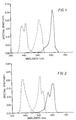
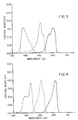
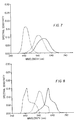
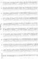
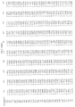
- ⁇ E ⁇ * ab and ⁇ were calculated as previously described for a variety of commercially available photographic elements. Table I contains representative photographic elements from that survey. Spectral sensitivity was measured for negative-working photographic elements by determining the exposures required to achieve a density of 0.2 above the minimum density formed in the absence of exposure. Spectral sensitivity for positive-working photographic elements was measured by determining the exposures required to achieve a density of 1.0. Included for reference are the MacAdam spectral sensitivities. The entry "J. Schwan and J. Graham" refers to spectral sensitivities selected from the ranges cited in U.S. Patent No.
- Entries 1-6 are representative of the normal range of colorimetric accuracy for photographic elements currently available based on measurements of their spectral sensitivities. Entry 6 marks the lower limit of ⁇ E ⁇ * ab of the photographic elements surveyed. Entry 7 establishes the value of ⁇ E ⁇ * ab for the MacAdam spectral sensitivities, the residual error is caused by the truncation of small negative responses present in the color-matching functions on which the MacAdam spectral sensitivities are based. The spectral sensitivities of the photographic elements listed in Table I are shown in FIGS. 1-9. The area under each spectral sensitivity response is normalized to unity for convenience.
- This invention has as its object to provide a photographic element comprised of a support and at least three silver halide emulsion layers, that records exposure information, wherein said exposure information is recorded in three image-recording units and wherein the spectral sensitivities of said image-recording units are chosen such that the average color error, ⁇ E ⁇ * ab , is less than or equal to 3.1, wherein said ⁇ E ⁇ * ab is computed for a specified set of test colors of known spectral reflectance, and the light source is specified as D 65 , and wherein said ⁇ E ⁇ * ab is the average CIE 1976 (L*a*b*) ⁇ E* ab between the CIE 1976 (L*a*b*)-space coordinates of said test colors and the CIE 1976 (L*a*b*)-space coordinates corresponding to transformed exposure signals, wherein said transformed exposure signals are formed by applying an exposure-space matrix to the exposure signals derived from said photographic element to transform said derived exposure signals to exposure signals corresponding to the color-
- the present invention contemplates obtaining a superior color image record using a photographic element containing at least three silver halide emulsion recording units each capable of recording an imagewise exposure where the spectral sensitivities of the three image recording units are non-coextensive and satisfy specified criteria for color recording capability and noise gain.
- the silver halide emulsion image recording units can take any convenient conventional form capable of forming a latent image in response to imagewise exposure within the selected regions of the spectrum.
- the emulsion image recording units contain grains of the same silver halide or combination of silver halides.
- the silver halide emulsion layer whose sensitivity falls predominantly in the blue region of the spectrum may rely on native spectral sensitivity.
- All emulsion image recording units can contain one or more spectral sensitizing dyes extending sensitivity to any desired region of the spectrum and/or enhancing sensitivity within the region of native sensitivity.
- the emulsion image recording units can be formed of any combination of silver halides. Further, it is immaterial whether the same silver halides are selected for each emulsion image recording unit.
- spectral sensitivities are chosen such that the value of ⁇ E* ⁇ ab calculated according to the procedure outlined above is less than or equal to 3.1.
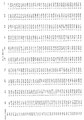
- One particularly preferred set of spectral sensitivities is defined in Table II.
- a spectral sensitivity corresponding to the definition of Table II is shown Table II.
- Photographic elements produced thus far have not contemplated using spectral sensitivities as shown in FIG. 10 because of an inability to produce an acceptable color image from such a photographic element using conventional means.
- Photographic elements satisfying this invention are particularly chosen from those which satisfy the color recording accuracy criterion defined by ⁇ E* ⁇ ab and would not be considered by those skilled in the art of photography to be useful in forming an acceptable color image using conventional methods of photographic image reproduction.
- those photographic elements exhibiting spectral sensitivities satisfying the ⁇ E* ⁇ ab requirement those spectral sensitivities which result in values of ⁇ as defined above of less than 6.5 are particularly preferred embodiments.
- each emulsion image recording unit produces a spectrally distinguishable image.
- a preferred way of producing spectrally distinguishable images is to have image dye formation occur in each image recording unit in proportion to the amount of silver development produced during processing where a different dye hue is produced in each of the three image recording units.
- the dye image requirement is preferably satisfied by incorporating in each emulsion image recording unit a different dye-forming coupler.
- Conventional photographic imaging dyes have relatively narrow absorption profiles, with half maximum absorption widths (hereinafter also referred to as half-peak absorption bands) typically well below 125 nm. It is preferred that the dye images produced in the three emulsion image recording units have non-overlapping half peak absorption bands.
- the half peak absorption band width of each image dye occupies a portion of the spectrum that is unoccupied by the half peak absorption band width of any other image dye contained in the photographic element after processing. Nevertheless, it is possible to discriminate between different image dyes even if some overlap of the half peak band widths occurs. It is common to have the three image dyes produced absorb primarily in the blue, green and red regions of the spectrum and are referred to as yellow, magenta and cyan image dyes, respectively.
- Structure I When Structure I is imagewise exposed and conventionally photographically processed, three spectrally distinguishable dye images can be produced, one in each of the three emulsion image recording units.
- scanning Structure I after processing first with a light beam having wavelengths absorbed primarily by one of the dye images and recording the modulation of the light beam, and repeating the scanning step twice more with light beams each having wavelengths absorbed primarily by one of the dye images which did not primarily absorb wavelengths of light contained in one of the other scanning beams, three separate image records can be obtained, corresponding to the images present in each of the three emulsion image recording units.
- the three light beams can be combined to allow a single scan of Structure I.
- the beam after modulation by Structure I is passed through three filters selected such that each transmits only the portion of the beam that is modulated primarily by one of the dye images.
- the information contained in the modulated light beam(s) is converted into image bearing electrical signals to form three separate representations of exposure information recorded by Structure I.
- the image bearing signals can be manipulated to increase the utility of the recorded exposure information. It is also contemplated that manipulation of the image bearing signals can accomplish desired aesthetic modifications to the recorded image.
- the captured information can be stored at any stage of the process for later use.
- FIG. 11 shows, in block diagram form, color imaging system apparatus 10, in accordance with a preferred embodiment of the invention.
- An image scanner 12 serves for scanning an image on positive or negative photographic element 14, and for producing R, G, B (red, green, and blue) image-bearing signals for each picture element of the image being scanned.
- a computer-based workstation 16 which receives the image-bearing signals from the scanner transforms the input image-bearing signals into intermediary image-bearing signals R', G', B'.
- the workstation allows for archival storage of the intermediary image-bearing signals using any of a variety of archival storage writing devices 18, and media such as magnetic tape or disk, or optical disk.
- the workstation enables an operator to view and edit the image.
- a video monitor 20 serves to display an image corresponding to an R", G", B" image-bearing signal provided by the workstation.
- Control apparatus 22 which may include a keyboard and cursor, enables the operator to provide image manipulation commands pertinent to modifying the video image displayed and the reproduced image to be made or stored.
- R, G, B image-bearing signals for example those produced by scanning an image from a negative or transparency photographic element with a transmission scanner, are first converted to image-bearing signals representing the relative trichromatic exposure values that each input photographic element received when it captured the original scene.
- U.S. Patent No. 5,267,030 describes the method and means for developing the transformations needed for this conversion and is herein included by reference.
- the exposures of step 4 may be further transformed by another matrix, a 3-dimensional LUT, or any other similar operation to arrive at exposure values that correspond to colorimetric values such as CIE XYZ values.
- the accuracy limit of this final transform will depend on the relationship of the spectral sensitivities of the image-capturing element to CIE color-matching functions.
- the three exposure records can be used to modulate light exposures necessary to recreate the image as a photographic negative, slide or print at will.
- the image can be viewed as a video display or printed by a variety of techniques beyond the bounds of classical photography--e.g., xerography, ink jet printing, thermal dye diffusion printing, etc.
- the image information may also be stored on a storage medium such as magnetic tape or optical disk for later use.
- the emulsion image recording units of differing spectral sensitivities for recording exposures within the visible spectrum can be formed of conventional silver halide emulsions or blends of silver halide emulsions.
- Preferred emulsions are negative-working emulsions and particularly negative-working silver bromoiodide emulsions.
- the invention is generally applicable to both positive or negative-working silver halide emulsions and to the full range of conventional approaches for forming dye images.
- Research Disclosure, Item 36544, published September 1994, (all cited sections of which are incorporated by reference) in Section I provides a summary of conventional emulsion grain features and in Section IV describes chemical sensitization. Research Disclosure is published by Kenneth Mason Publications, Ltd., Emsworth, Hampshire P010 7DD, England.
- the silver halide emulsions incorporated in the photographic element can obtain their sensitivity to light in the visible region of the spectrum by any combination of native silver halide response or by the addition of spectral sensitizing dyes.
- Spectral sensitizing dyes useful in the practice of the invention include the polymethine dye class, which includes the cyanines, merocyanines, complex cyanines and merocyanines (i.e., tri-, tetra- and poly-nuclear cyanines and merocyanines), oxonols, hemioxonols, styryls, merostyryls, streptocyanines, hemicyanines and arylidenes.
- the cyanine spectral sensitizing dyes include, joined by a methine linkage, two basic heterocyclic nuclei, such as those derived from quinolinium, pyridinium, isoquinolinium, 3H-indolium, benz[e]indolium, oxazolium, thiazolium, selenazolinium, imidazolium, benzoxazolinium, benzothiazolium, benzoselenazolium, benzimidazolium, naphthoxazolium, naphthothiazolium, naphthoselenazolium, thiazolinium, dihydronaphthothiazolium, pyrylium and imidazopyrazinium quaternary salts.
- two basic heterocyclic nuclei such as those derived from quinolinium, pyridinium, isoquinolinium, 3H-indolium, benz[e]indolium, oxazol
- the basic heterocyclic nuclei can also include tellurazoles or oxatellurazoles as described by Gunther et al U.S. Patent Nos. 4,575,483, 4,576,905 and 4,599,410.
- Varied cyanine dyes, including varied substituents, are described in Parton et al U.S. Patent No. 4,871,656 (heptamethine dyes with sulfoethyl or carboxyethyl nitrogen substituents), Ficken et al U.S. Patent No. 4,996,141 (simple cyanine with particular substituents on a thiazole ring), Tanaka et al U.S. Patent No.
- Patent No. 5,216,166 bridge nitro containing substituent
- MacIntyre et al U.S. Patent No. 5,135,845 fluoro substituted
- Ikegawa et al U.S. Patent No. 5,198,332 trimethine benzoxazoles with substituents defined by STERIMOL parameters
- Kagawa et al EPO 0 362 387 sulfo substituent on benzo or naphtho back ring
- EPO 0 521 632 benzothiazole with alkoxy substituents
- Hioki et al EPO 0 443 466 with aromatic polycyclic substituent
- 0 474 047 with aromatic polycyclic substituent
- Ikegawa et al EPO 0 530 511 nitrogen sulfonamide or carbonamide type substituents
- Nagaoki et al EPO 0 534 283 dye with various particular emulsions
- Cyanine dyes with carbocyclic rings in the methine chain linking nuclei are described in Lea et al U.S. Patent No. 4,959,294 (Cl or Br substituent on bridging ring), Sato et al U.S. Patent No. 4,999,282, Muenter et al U.S. Patent No. 5,013,642 (fused bridging rings), Parton et al U.S. Patent No. 5,108,882 (fused bridging rings), Hioki et al U.S. Patent Nos. 5,166,047 (also includes merocyanines with carbocyclic bridging ring), 5,175,080, and 4,939,080, Parton et al U.S.
- Trinuclear type dyes which have a general cyanine type structure but with a heterocyclic nucleus in the bridging methine chain are described in Arai et al U.S. Patent No. 4,945,036, Mee et al U.S. Patent No. 4,965,183, Ono U.S. Patent No. 4,920,040 (trinuclear, cyanine structure with intermediate heterocyclic ring), Koya et al U.S. Patent No. 5,250,692, Bolger et al U.S. Patent No. 5,079,139 and Kaneko et al U.S. Patent No. 5,234,806.
- Cyanine dyes which have an indole nucleus are illustrated by Proehl et al U.S. Patent No. 4,876,181, Usagawa et al U.S. Patent No. 5,057,406, Kaneko et al U.S. Patent Nos. 5,077,186 and 5,153,114, Proehl et al EPO 0 251 282 and Fichen et al U.K. Patent No. 2,235,463.
- the merocyanine spectral sensitizing dyes include, joined by a methine linkage, a basic heterocyclic nucleus of the cyanine-dye type and an acidic nucleus such as can be derived from barbituric acid, 2-thiobarbituric acid, rhodanine, hydantoin, 2-thiohydantoin, 4-thiohydantoin, 2-pyrazolin-5-one, 2-isoxazolin-5-one, indan-1,3-dione, cyclohexan-1,3-dione, 1,3-dioxane-4,6-dione, pyrazolin-3,5-dione, pentan-2,4-dione, alkylsulfonyl acetonitrile, malononitrile, isoquinolin-4-one, and chroman-2.4-dione.
- the merocyanine dyes may include telluracyclohexanedione as acidic nucleus as described in Japanese Patent Application JA 51/136,420.
- Merocyanine type dyes are described in Fabricius et al U.S. Patent Nos. 5,108,887, and 5,102,781, Link U.S. Patent No. 5,077,191, Callant et al U.S. Patent No. 5,116,722, Diehl et al EPO 0 446 845, Ito et al EPO 0 540 295 (trinuclear merocyanine) and U.K. Patent No. 2,250,298.
- sensitizing dyes include those described in Hioki et al U.S. Patent Nos. 4,814,265 (azulene nucleus) and 5,003,077 (methine dyes with a cycloheptimidazole nucleus), Okazaki et al U.S. Patent No. 4,839,269 (dyes with two or more cyclodextran groups), Wheeler U.S. Patent No. 4,614,801 (cyanine dyes with an indolizine nucleus), Burrows et al U.S. Patent No. 4,857,450 (hemicyanines), Roberts et al U.S. Patent No.
- One or more spectral sensitizing dyes may be used to achieve spectral sensitivities satisfying the requirements of the invention.
- Dyes with sensitizing maxima at wavelengths throughout the visible and infrared spectrum and with a great variety of spectral sensitivity curve shapes are known. The choice and relative proportions of dyes is determined based on the ability of the resulting sensitivity of the photographic element to satisfy the requirements of the invention. Dyes with overlapping spectral sensitivity curves will often yield in combination a sensitivity exhibiting characteristics of the individual dyes. Thus, it is possible to use combinations of dyes with different maxima to achieve a spectral sensitivity curve with a maximum intermediate to the sensitizing maxima of the individual dyes.
- Combinations of spectral sensitizing dyes can be used which result in supersensitization--that is, spectral sensitization greater in some spectral region than that from any concentration of one of the dyes alone or that which would result from the additive effect of the dyes.
- Supersensitization can be achieved with selected combinations of spectral sensitizing dyes and other addenda such as stabilizers and antifoggants, development accelerators or inhibitors, coating aids, brighteners and antistatic agents. Any one of several mechanisms, as well as compounds which can be responsible for supersensitization, are discussed by Gilman, Photographic Science and Engineering, Vol. 18, 1974, pp. 418-430.
- Spectral sensitizing dyes can be added at any stage during the emulsion preparation. They may be added at the beginning of or during precipitation as described by Wall, Photographic Emulsions, American Photographic Publishing Co., Boston, 1929, p. 65, Hill U.S. Patent No. 2,735,766, Philippaerts et al U.S. Patent No. 3,628,960, Locker U.S. Patent No. 4,183,756, Locker et al U.S. Patent No. 4,225,666 and Research Disclosure, Vol. 181, May, 1979, Item 18155, Tani et al EPO 0 301 508, and Tani et al U.S. Patent No. 4,741,995.
- halide ion that forms a silver halide less soluble than that of the grains can be adsorbed to the emulsion grains to promote aggregation and adsorption of the spectral sensitizing dyes as described by U.K. Patent No. 1,413,826 and Kofron et al U.S. Patent No. 4,439,520.
- Post-processing dye stain can be reduced by the proximity to the dyed emulsion layer of fine high-iodide grains as described by Dickerson U.S. Patent No. 4,520,098.
- the spectral sensitizing dyes can be added to the silver halide emulsion as solutions in water or solvents such as methanol, ethanol, acetone or pyridine, dissolved in surfactant solutions as described by Sakai et al U.S. Patent No. 3,822,135 or as dispersions as described by Owens et al U.S. Patent No. 3,469,987 and Japanese Patent Application 24185/71.
- the dyes can be selectively adsorbed to particular crystallographic faces of the emulsion grain as a means of restricting chemical sensitization centers to other faces, as described by Mifune et al EPO 0 302 528.
- Substituents which can perform additional photographic functions such as direct-positive nucleation or development acceleration can be included in the dye structure, as described by Spence et al U.S. Patent Nos. 3,718,470 and 3,854,956, Research Disclosure, Vol. 151, November, 1976, Item 15162, and Okazaki et al U.S. Patent No. 4,800,154.
- the spectral sensitizing dyes may be used in conjunction with poorly adsorbed luminescent dyes, as described by Miyasaka et al U.S. Patent Nos. 4,908,303, 4,876,183 and 4,820,606, EPO 0 270 079, EPO 0 270 082 and EPO 0 278 510 and Sugimoto et al U.S. Patent No. 4,963,476.
- Section XV of Research Disclosure, Vol. 365, September, 1994, Item 36544 describes a wide selection of supports useful for photographic elements.
- the photographic support in Structure I can take the form of any conventional transparent or reflective support as described in Section XV.
- the inclusion in Structure I of other conventional photographic element features, such as one or more of the hardeners summarized in Section II, antifoggants and stabilizers as described in Section VII, materials which may be incorporated in one or more of the coated layers to assist coating or alter the physical properties of the coated layers as described in Section IX conform to the routine practices of the art and require no detailed description.
- the first step of the process of the invention is to photographically process Structure I after it has been imagewise exposed to produce separate dye images in the three emulsion image recording units.
- Any convenient conventional color processing employed in silver halide photography can be undertaken.
- Conventional photographic processing of color photographic elements particularly suited to the practice of this invention includes those summarized in Item 36544, cited above, Section XVIII, particularly the color reversal processing of sub-section B.
- a typical sequence of steps includes black-and-white development of the exposed silver halide grains, stopping development, rendering the residual silver halide grains developable either chemically of by exposure to light, development of remaining silver halide grains to produce dye images, bleaching of elemental silver and fixing to remove silver halide. Washing may be interposed between successive processing steps.
- a simple technique for scanning is to scan the photographically processed Structure I point-by-point along a series of laterally offset parallel scan paths.
- the photographic support is transparent, as is preferred, the intensity of light passing through the photographic element at a scanning point is detected by a sensor which converts radiation received into an electrical signal.
- the photographic support can be reflective and the sensed signal can be reflected from the support.
- the electrical signal is passed through an analog to digital converter and sent to memory in a digital computer together with locant information required for pixel location within the image.
- locant information required for pixel location within the image.
- successive image density scans can be identical to the first.
- Enhancing image sharpness and minimizing the impact of aberrant pixel signals are common approaches to enhancing image quality when images are represented as electronic signals.
- a conventional technique for minimizing the impact of aberrant pixel signals is to adjust each pixel density reading to a weighted average value bv factoring in readings from adjacent pixels, closer adjacent pixels being weighted more heavily.
- the invention is described in terms of point-by-point scanning, it is appreciated that conventional approaches to improving image quality are contemplated.
- Illustrative systems of scan signal manipulation, including techniques for maximizing the quality of image records are disclosed by Bayer U.S. Patent No. 4,553,165, Urabe et al U.S. Patent No. 4,591,923, Sasaki et al U.S.
- the image dye hue of each emulsion image recording unit is chosen according to the following relationship: yellow dye represents blue exposure information, magenta dye represents green exposure information, and cyan dye represents red exposure information. It is recognized that the image dye hue of an emulsion image recording unit of a photographic element satisfying the requirements of the invention is not required to correspond to the region of the spectrum recorded as described above since the element is intended to be scanned. The correspondence between image record hue and the region of the spectrum recorded can be altered as required in the digital computer.
- a preferred photographic element is illustrated by Structure II: Overcoat Fast Blue Emulsion Image Recording Layer Slow Blue Emulsion Image Recording Layer Interlayer #1 Fast Green Emulsion Image Recording Layer Slow Green Emulsion Image Recording Layer Interlayer #2 Fast Red Emulsion Image Recording Layer Slow Red Emulsion Image Recording Layer Transparent Film Support Antihalation Layer Structure II
- Structure II demonstrates one of numerous possible embodiments which satisfies all of the requirements of the general discussion of Structure I.
- Structure II can be used for photographic elements intended to produce either color reversal or negative images upon photographic processing, but is particularly suited for color reversal image forming elements.
- Structure I above was chosen to demonstrate the simplest photographic element contemplated for practicing the invention. It is recognized that Structure I could be readily expanded by including two or more emulsion layers of similar spectral sensitivity for each of the three emulsion image recording units shown and additional layers can be added between any or all of the image recording units.
- One common technique for improving the speed-granularity relationship of an image produced in a silver halide photographic element is to provide multiple (usually two or three) superimposed silver halide emulsion layers differing in speed (i.e., differing in their threshold sensitivities) to record exposing light from each selected region of the spectrum.
- Hellmig U.S. Patent No. 3,846,135 discloses fast over slow emulsion layer arrangements in black-and-white photographic elements while Eeles et al U.S. Patent No. 4,184,876 and Kofron et al U.S.
- Patent No. 4,439,520 discloses arrangements in color photographic elements. To obtain the most favorable speed-granularity relationship (signal to noise level), a difference in threshold speeds of emulsion layers contributing to the formation of one exposure record is preferably obtained by varying the average grain size of the emulsions in one layer relative to the others. Each emulsion component is optimally chemically sensitized. In a preferred form of the invention, each image recording unit is composed of two emulsion layers. When more than one emulsion layer is used to form an emulsion image recording unit, the image dyes produced by each of the contributing emulsion layers are chosen to produce similar dye hues after processing.
- an emulsion image recording unit composed of two or more image recording emulsion layers can produce upon photographic processing spectrally distinguishable records in each sub-layer as disclosed by Sutton U. S. Patent No. 5,314,794, the disclosure of which is here incorporated by reference.
- the preferred silver halide emulsions are silver bromoiodide negative-working emulsions. Negative-working emulsions are preferred, since they are simpler in their structure and preparation. Silver bromoiodide grain compositions provide the most favorable relationship of photographic sensitivity (speed) to granularity (noise) and are generally preferred for camera speed (>ISO 25) imaging. While any conventional iodide level can be employed, only low levels of iodide are required for increased sensitivity. Iodide levels as low as 0.5 mole percent, based on total silver are contemplated in preferred embodiments. Iodide levels in the range of from 3.0 to 6.0 mole percent based on total silver are contemplated for use in preferred embodiments.
- silver bromoiodide emulsions are referred to as silver bromoiodide emulsions, it is appreciated that minor amounts of chloride can be present.
- silver bromoiodide grains that are epitaxially silver chloride sensitized are specifically contemplated. Examples of such emulsions are provided by Maskasky U.S. Patent Nos. 4,435,501 and 4,463,087.
- tabular grain emulsion refers to an emulsion in which greater than 50 percent (preferably greater than 70 percent) of the total grain projected area is accounted for by tabular grains.
- preferred tabular grain emulsions are those in which the projected area criterion above is satisfied by tabular grains having thicknesses of less than 0.3 mm (optimally less than 0.2 mm), an average aspect ratio (ECD/t) of greater than 8 (optimally greater than 12), and/or an average tabularity (ECD/t 2 ) of greater than 25 (optimally greater than 100), where ECD is the mean equivalent circular diameter and t is the mean thickness of the tabular grains, both measured in micrometers (mm).
- ECD average aspect ratio
- ECD/t 2 average tabularity
- Specific examples of preferred silver bromoiodide emulsions include Research Disclosure, Item 22534, January 1983; Wilgus et al U.S. Patent No.
- Interlayers #1 and #2 are hydrophilic colloid layers. Each interlayer preferably contains a conventional oxidized developing agent scavenger to minimize or eliminate color contamination by oxidized developing agent diffusion from one emulsion layer to a next adjacent layer. Interlayer #1 preferably contains a processing solution bleachable yellow absorber such as Carey Lea Silver (CLS) or decolorizable yellow dye to decrease the sensitivity of underlying layers to light in the blue region of the spectrum arising from native or dyed sensitivity. Additional process decolorizable filter dyes may be contained in the Overcoat and/or Interlayers #1 and #2 to further alter the effective spectral sensitivities of underlying layers. Useful absorbers can absorb light in the visible spectrum as well as in the ultraviolet and near infrared regions.
- CLS Carey Lea Silver
- Absorbing materials can include filter dyes such as the pyrazolone oxonol dyes of Gaspar U.S. Patent No. 2,274,782 and Adachi et al U.S. Patent No. 4,833,246, Diehl et al U.S. Patent No. 4,877,721, Tanaka et al U.S. Patent No. 4,904,578, Ohno et al U.S. Patent No. 4,933,268, Kawashima et al U.S. Patent No. 4,960,686, Murai et al U.S. Patent No. 4,996,138, Waki et al U.S. Patent No.
- filter dyes such as the pyrazolone oxonol dyes of Gaspar U.S. Patent No. 2,274,782 and Adachi et al U.S. Patent No. 4,833,246, Diehl et al U.S. Patent No. 4,877,721, Tanaka et al U.S. Patent No.
- Ultraviolet absorbers are also known, such as the cyanomethyl sulfone-derived merocyanines of Oliver U.S. Patent No. 3,723,154, the thiazolidones, benzotriazoles and thiazolothiazoles of Sawdey U.S. Patent Nos. 2,739,888, 3,253,921 and 3,250,617, Sawdey et al U.S. Patent No. 2,739,971, Hirose et al U.S. Patent No. 4,783,394, Takahashi U.S. Patent No. 5,200,307, Tanji et al U.S. Patent No.
- the dyes and ultraviolet absorbers can be mordanted as illustrated by Jones et al U.S. Patent No. 3,282,699 and Heseltine et al U.S. Patent Nos. 3,455,693, 3,438,779 and Foss et al U.S. Patent No. 5,169,747.
- Absorbing dyes can be added as particulate dispersions, as described by Lemahieu et al U.S. Patent No. 4,092,168, Diehl et al WO 88/04795 and EPO 0 274 723, and Factor et al EPO 0 299 435. Additional particulate dispersions of absorbing dyes are described in Factor et al U.S. Patent No. 4,900,653, Diehl et al U.S. Patent No. 4,940,654 (dyes with groups having ionizable protons other than carboxy), Factor et al U.S. Patent No.
- Absorbing dyes can absorb infrared radiation, as described by Proehl et al EPO 0 251 282, Parton et al EPO 0 288 076, and Japanese Patent Application JA 62/123454. Further infrared absorbing dyes are described in Parton et al U.S. Patent No. 4,933,269 (cyanines with carbocyclic ring in bridge), Hall et al U.S. Patent No. 5,245,045 (heptamethine oxonols), Harada EPO 0 568 857. Particular infrared absorbing dyes include those of the cyanine type with indole nuclei such as described in West et al U.S. Patent No.
- Absorbing dyes having specific substituents intended to assist in their removal during processing by solubilization, oxidation or other methods are described in Yagihara et al U.S. Patent No. 4,923,789, Harder et al U.S. Patent No. 5,158,865, Karino et al U.S. Patent No. 5,188,928, Kawashima et al EPO 0 409 117 (particular amido, ureido and the like solubilizing groups), Matushita EPO 0 508 432 and Mooberry et al WO 92/21064.
- Absorbing dyes or dye combinations used to obtain absorption at particular wavelengths, manner of incorporating them in a photographic element, or absorbing dyes plus other components are described in Ailliet et al U.S. Patent No. 4,770,984 (location of absorber dyes), Szajewski U.S. Patent No. 4,855,220 (dye absorbing in region to which layer underneath is sensitized), Toya et al U.S. Patent No. 5,147,769 (dye in oil droplet dispersion or polymer latex), Stockel et al U.S. Patent No.
- dye images are produced by dye-forming couplers.
- Couplers capable of forming yellow, magenta, cyan and near infrared absorbing dyes on development are preferred.
- the couplers forming yellow, magenta and cyan dyes are preferred, since a large selection of photographically optimized couplers of these types are known and in current use in silver halide photography (refer to Research Disclosure, Item 36544, Section X, cited above, and to James The Theory of the Photographic Process, 4th Ed., Macmillan, New York, 1977, Chapter 12, Section III, pp. 353-363).
- the couplers are selected so that the exposure information obtained primarily in the red region of the spectrum results in a cyan dye image, the exposure information obtained primarily in the green region of the spectrum results in a magenta dye image, and the exposure information obtained primarily in the blue region of the spectrum results in a yellow dye image.
- This correspondence between image dye hue and spectral region recorded when used with a photographic element and photographic process producing a reversal color image facilitates direct viewing of the exposed and photographically processed photographic element.
- the stoichiometric relationship between the amount of silver development and coupler can take on any value useful in controlling density production or image granularity.
- Emulsion containing layers can contain conventional oxidized developing agent scavengers to modify the relationship between dye image producing silver development and the amount of density produced during photographic development.
- Oxidized developing agent scavengers are described in Research Disclosure, Item 36544, cited above, Section X, sub-section D.
- a conventional processing solution decolorizable antihalation layer is shown coated on the surface of the transparent photographic support opposite the image recording units.
- the antihalation layer can be located between the first emulsion layer above the support and the support. At the latter location it is more effective in improving image sharpness, since reflection at the interface of the first-coated image recording unit and the support is minimized, but at this location it is also less accessible to the processing solutions.
- Specific examples of antihalation materials and their decoloration are provided by Research Disclosure, Item 36544, cited above, Section VIII, sub-section B.
- An antihalation layer is a preferred feature, but not essential to imaging.
- the photographic element is processed to produce a positive image.
- Conventional reversal processing includes the steps of black-and-white development of the exposed silver halide grains, stopping development, rendering residual silver halide grains developable by chemical treatment or exposure to actinic radiation, color development to produce a dye image corresponding to the amount of silver halide not imagewise exposed, bleaching of the silver and fixing to remove silver halide.
- the photographically processed photographic element is scanned as described above to produce three electronic records.
- the electronic records obtained are mathematically manipulated to yield a record of the original scene that is advantaged for colorimetric accuracy relative to the photographic elements of the prior art.
- Color Negative Photographic Element and Process Overcoat Fast Blue Emulsion Image Recording Layer Slow Blue Emulsion Image Recording Layer Interlayer #1 Fast Green Emulsion Image Recording Layer Mid Green Emulsion Image Recording Layer Slow Green Emulsion Image Recording Layer Interlayer #2 Fast Red Emulsion Image Recording Layer Mid Red Emulsion Image Recording Layer Slow Red Emulsion Image Recording Layer Antihalation Layer Transparent Film Support Auxiliary Information Recording Unit Structure III
- Structure III described below, demonstrates one of numerous possible embodiments particularly useful for photographic elements and photographic processes which produce negative images. Structure III satisfies all of the requirements of the general discussion of Structure I and features not explicitly otherwise described preferably conform to the comparable features of Structure II described above.
- the highest signal-to-noise ratio of an image recording unit made up of a set of emulsion layers of differing threshold sensitivities intended to record exposures in the same region of the spectrum is obtained by controlling the amount of density produced by each contributing emulsion layer. Since the dye image formed in each emulsion layer of the set is of the same hue, the resulting overall dye image cannot be resolved into its component contributions by the individual layers of the set.
- the most common approach to reducing image granularity in photographic elements photographically processed to produce a negative image is to "coupler starve" some of the emulsion layers.
- the term “coupler starve” means simply that there is a stoichiometric deficiency of dye image providing material.
- Preferred embodiments of photographic elements intended to produce negative images after photographic processing are not generally useful for direct viewing.
- the relationship between the spectral distribution of the exposing radiation recorded and the hue of the associated dye image in each image recording unit formed during photographic processing can take any convenient form.
- any or all layers within the photographic element may contain colored image dye forming couplers to form integral masks which partially or completely compensate for the interdependencies of image bearing signals obtained by scanning the exposed and photographically processed photographic element.
- Colored image dye forming couplers useful for this application are described in Research Disclosure, Item 36544, cited above, section XII, sub-sections 1 and 2.
- each emulsion layer containing a dye-forming coupler or other conventional dye image providing material can have its image structure improved by also including a material capable of inhibiting development, such as a development inhibitor releasing (DIR) coupler.
- DIR couplers of any conventional type can be incorporated in any layer of the photographic element, including interlayers and any emulsion layer that does not form a dye image.
- Exemplary development inhibitors are illustrated by Whitmore et al U.S. Patent No. 3,148,062, Barr et al U.S. Patent No. 3,227,554, Hotta et al U.S. Patent No. 4,409,323, Harder U.S. Patent No. 4,684,604, and Adachi et al U.S. Patent No. 4,740,453, the disclosures of which are here incorporated by reference.
- Photographic processing of the exposed photographic element to produce a negative image consists of color development of the exposed silver halide grains, stopping development, bleaching of elemental silver, and fixing of silver halide. Washing steps may be added between specified processing steps. Photographic processes resulting in negative images are desired because of their simplicity.
- the auxiliary information recording unit is shown in Structure III for the purpose of illustrating (1) that information recording units can be present in addition to those required to produce the image of the subject being replicated and (2) that the location of information recording units is not restricted to one side of the support.
- the auxiliary information recording unit can be used to incorporate into the photographic element a scannable record usefully stored with the photographic record.
- the auxiliary information recording unit can be exposed with a code pattern indicative of the date, time, aperture, shutter speed, frame locant and/or photographic element identification usefully correlated with the photographic image information.
- the back side (the side of the support opposite the emulsion layers) of the photographic element can be conveniently exposed to auxiliary information immediately following shutter closure concluding imagewise exposure of the front side (the emulsion layer side) of the photographic element.
- Films containing a magnetic recording layer such as any of those disclosed in Research Disclosure, Item 34390, Nov. 1992, p. 869, are specifically contemplated.
- Recent additional publications relating to a transparent magnetic recording layer on a photographic element are illustrated by Sakakibara U.S. Patent Nos. 5,215,874 and 5,147,768, Kitagawa U.S. Patent No. 5,187,518, Nishiura U.S. Patent No. 5,188,789, Mori U.S. Patent No.
- the photographic elements can contain an edge region particularly adapted for scanning, such as those employed to form sound tracks, as illustrated by Sakakibara U.S. Patent Nos. 5,147,768 and 5,215,84, Kitagawa U.S. Patent No. 5,187,518, Nishiura U.S. Patent No. 5,188,789, Mori U.S. Patent No. 5,227,283, Yokota U.S. Patent No. 5,229,259 and Japanese Patent Application 92/203,098, Hirose et al U.S. Patent No.
- the photographic elements described above produce spectrally distinguishable dye images upon processing which can be scanned using conventional methods of photographic element scanning. Since photographic elements which satisfy the invention are intended to be scanned and the resultant electronic signals mathematically manipulated prior to production of the final output image, alternate means of producing distinguishable images are also useful in the practice of this invention. Evans et al U.S. Patent No. 5,350,651 and U.S. Serial No. 198,415, Simons U.S. Patent No. 5,350,644 and U.S. Serial No. 199,862, and Gasper et al U.S. Patent No. 5,350,650 and U.S. Serial No. 199,866, the disclosures of which are here incorporated by reference, illustrate photographic elements and means of distinguishing the images formed upon photographic processing of non-image dye forming layers which, apart from the selection of the spectral sensitivity satisfy the imaging requirements of this invention.
- the invention has been described in terms of one method for transforming image-bearing signals from a scanner to signals which represent the recorded exposure values of the image-capturing photographic element comprised of a specific series of discrete operations.
- Other methods such as direct calibration relating recorded exposures to scanned signals or values, may also be used.
- a direct calibration relating scanner signals from a scanner to original scene colorimetric values can also be used.
- photographic elements incorporating the spectral sensitivities of this invention will yield color signals which closely approximate colorimetric values of the original scene. Transformations can be accomplished using look-up tables or explicit mathematical functions dependent on one or more signals obtained by scanning the exposed and processed photographic element.
- a photographic element (Invention Film #1) useful for the practice of the invention was prepared by coating onto a transparent photographic support. The following layers were coated to prepare Invention Film #1 beginning with the layer closest to the photographic support:
- Cyan dye forming coupler (CC1) had the following structure:
- Magenta dye forming coupler (MC1) had the following structure:
- Magenta dye forming coupler had the following structure:
- Yellow dye forming coupler had the following structure:
- Oxidized developer scavenger (DOX1) had the following structure:
- Oxidized developer scavenger (DOX2) had the following structure:
- Yellow filter dye (YFD1) had the following structure:
- Yellow filter dye (YFD2) had the following structure:
- UV filter dye (UV1) had the following structure:
- UV filter dye (UV2) had the following structure:
- Emulsion Component Average Grain Size Mole % Iodide Spectral Sensitizing Dye mmole of dye/mole silver
- Yellow spectral sensitizing dye had the following structure:
- Yellow spectral sensitizing dye had the following structure:
- Magenta spectral sensitizing dye (MSD1) had the following structure:
- Magenta spectral sensitizing dye had the following structure:
- Magenta spectral sensitizing dye had the following structure:
- Cyan spectral sensitizing dye (CSD1) had the following structure:
- Cyan spectral sensitizing dye (CSD2) had the following structure:
- Cyan spectral sensitizing dye (CSD3) had the following structure:
- 4-hydroxy-6-methyl-1,3,3A,7-tetraazindene, sodium salt was included in each imaging emulsion containing layer and surfactants were included in all layers to facilitate coating.
- Comparison Film #1 was prepared by coating onto a transparent photographic support. The following layers were coated to prepare Comparison Film #1 beginning with the layer closest to the photographic support:
- Emulsion Component Average Grain Size Mole % Iodide Spectral Sensitizing Dye mmole of dye/mole silver
- Magenta spectral sensitizing dye had the following structure:
- Magenta spectral sensitizing dye had the following structure:
- Cyan spectral sensitizing dye (CSD4) had the following structure:
- Cyan spectral sensitizing dye (CSD5) had the following structure:
- 4-hydroxy-6-methyl-1,3,3A,7-tetraazindene, sodium salt was included in each imaging emulsion containing layer and surfactants were included in all layers to facilitate coating.
- Samples of the Invention and Comparison Films were exposed in a sensitometer using a light source passed through a graduated neutral density step wedge.
- the central wavelength of the exposing light source was varied in 10 nm increments and a separate exposure was made for each.
- the exposure source intensity and exposure time were known for each exposure condition.
- the exposed photographic element was processed according to the following procedure:
- the red, green, and blue transmission integral densities of the exposed and processed photographic element were measured using a densitometer having Status A responsivities.
- Spectral sensitivity was measured by determining the exposure values required to achieve a density of 1.0 for each exposing wavelength.
- a plot of spectral sensitivity as a function of exposing wavelength for the Invention and Comparison Films are shown in FIGS. 12 and 2, respectively.
- Matrix M for Invention Film#1 was determined to be as follows:
- Invention Film #2 was exposed and chemically processed as described in example 1.
- the spectral sensitivity of Invention Film #2 was determined as described above and is shown in FIG. 13.
- Matrix M was determined to be the following: Values of ⁇ E* ⁇ ab and ⁇ for Invention Film #2 were determined to be 2.0 and 4.4, respectively. As seen by the values of ⁇ E* ⁇ ab and ⁇ Invention Film #2 has comparable colorimetric recording accuracy to Invention Film #1, but superior signal to noise performance.
Abstract
and noise-gain factor, Ψ, defined as the sum of the square roots of the sum of the squares of each row of the elements in the exposure space matrix is less than or equal to 6.5.
Description
- Reference is made to commonly-assigned U.S. Patent Application Serial No. 08/466,862 filed June 6, 1995 entitled "Method For Producing an Electronic Image From a Photographic Element" by Giorgianni et al, the disclosure of which is incorporated herein.
- The present invention relates to photographic elements whose spectral sensitivities are chosen to achieve specific color reproduction and noise performance.
- In classical black-and-white photography a photographic element containing a silver halide emulsion layer coated on a transparent film support is imagewise exposed to light. This produces a latent image within the emulsion layer. The film is then photographically processed to transform the latent image into a silver image that is a negative image of the subject photographed. Photographic processing involves developing (reducing silver halide grains containing latent image sites to silver), stopping development, and fixing (dissolving undeveloped silver halide grains). The resulting processed photographic element, commonly referred to as a negative, is placed between a uniform exposure light source and a second photographic element, commonly referred to as a photographic paper, containing a silver halide emulsion layer coated on a white paper support. Exposure of the emulsion layer of the photographic paper through the negative produces a latent image in the photographic paper that is a positive image of the subject originally photographed. Photographic processing of the photographic paper produces a positive silver image. The image bearing photographic paper is commonly referred to as a print.
- In a well known, but much less common, variant of classical black-and-white photography a direct positive emulsion can be employed, so named because the first image produced on processing is a positive silver image, obviating any necessity of printing to obtain a viewable positive image. Another well known variation, commonly referred to as instant photography, involves imagewise transfer of silver ion to a physical development site in a receiver to produce a viewable transferred silver image.
- In classical color photography the photographic element contains three superimposed silver halide emulsion layer units, one for forming a latent image corresponding to blue light (i.e., blue) exposure, one for forming a latent image corresponding to green exposure and one for forming a latent image corresponding to red exposure. During photographic processing, developing agent oxidized upon reduction of latent image containing grains reacts to produce a dye image with developed silver being an unused product of the oxidation-reduction development reaction. Silver is removed by bleaching and fixingduring photographic processing. The image dyes are complementary subtractive primaries--that is, yellow, magenta and cyan dye images are formed in the blue, green and red image recording units, respectively. This produces negative dye images (i.e., blue, green and red subject features appear yellow, magenta and cyan, respectively). Exposure of color paper through the color negative followed by photographic processing produces a positive color print Again, bleaching and fixing remove developed silver and residual silver halide that would otherwise adversely affect the color print.
- In one common variation of classical color photography reversal processing is undertaken to produce a positive dye image in the color photographic element, commonly referred to as a slide, the image typically being viewed by projection. In another common variation, referred to as color image transfer or instant photography, image dyes are transferred to a receiver for viewing.
- In each of the classical forms of photography noted above the final image is intended to be viewed by the human eye. Thus, the conformation of the viewed image to the subject image, absent intended aesthetic departures, is the criterion of photographic success.
- It is well known to those skilled in the art that the colors reproduced on, or produced from, a photographic color-imaging element generally are not colorimetric matches of the colors originally photographed by the element Colorimetric errors can be caused by the color recording and color reproduction properties of the photographic element and system. The distinction between the color recording and color reproduction properties of a photographic element is fundamental. Color recording by a photographic element is determined by its spectral sensitivity. The spectral sensitivity of a photographic element is a measure of the amount of exposure of a given wavelength required to achieve a specific photographic response. Color reproduction by a photographic imaging system depends not only on the color recording properties of the capturing element as described above, but also on all subsequent steps in the image forming process. The color reproduction properties of the imaging element or system can vary the gamma, color saturation, hue, etc. but cannot fully compensate for problems caused by spectral sensitivities which are not correlates of the human visual system. Metamers are an example of such a problem. Metamerism occurs when two stimuli with different spectral reflectance appear identical to the eye under a specific illuminant. A photographic element whose spectral sensitivities differ from that of the human visual system record the stimuli differently. Once recorded as disparate, a photographic element's color reproduction will only amplify or minimize that difference.
- In certain applications, it is desirable to form image representations that correspond more closely to the colorimetric values of the colors of the original scene recorded on the photographic color-imaging element rather than form image representations which correspond to the reproductions of those colors by the element itself. Examples of such applications include, but are not limited to, the production of medical and other technical images, product catalogues, magazine advertisements, artwork reproductions, and other applications where it is desirable to obtain color information which is a colorimetrically accurate record of the colors of the original scene. In these applications, the alterations in the color reproduction of the original scene colors by the color recording and color reproduction properties of the imaging element are undesirable.
- To achieve absolute colorimetric accuracy during recording, the photographic element 's spectral sensitivity must be color-matching functions. Color-matching functions are defined as the amounts of three linearly independent color stimuli (primaries) required to match a series of monochromatic stimuli of equal radiant power at each wavelength of the spectrum. A set of three color stimuli is linearly independent when none of the stimuli can be matched by a mixture of the other two. Negative amounts of a color stimulus are routine in color-matching functions and are interpreted as the amount of that color stimulus which would be added to the color being matched and not to the mixture itself. Color-matching functions for any real set of primaries must have negative portions. It is possible to functionally transform from one set of color-matching functions to any other set of color-matching functions using a simple linear transformation. By using the color-matching functions which correspond to the primaries of the intended output device or medium as the photographic element's spectral sensitivities, no additional color signal processing is necessary.
- The selection of spectral sensitivities for colorimetric recording is based on the primaries of the imaging system in question. The primaries in a photographic system are defined by the imaging dyes of the element used to form the final reproduction of the recorded image, the spectral composition of which is all positive. Color-matching functions for a set of all-positive primaries contain negative responses. Within the realm of known photographic mechanisms, it is not possible to produce a photographic element having spectral sensitivities whose response is negative.
- To date, no available photographic system has been developed which has spectral sensitivities which approximate a set of color-matching functions or a linearly combination thereof. Numerous ranges of spectral sensitization have been claimed for specific color reproduction advantage, but none approximate color-matching functions as spectral sensitivities and therefore do not have colorimetrically accurate color recording or reproduction.
- A photographic element could be built using all-positive color-matching functions as spectral sensitivities, but these color-matching functions would not correspond to the primaries of the photographic system. Those skilled in the art will recognize that linear exposure-space signal processing (matrixing) would be required to transform the linear exposures recorded by all-positive color-matching-function spectral sensitivities to the linear exposures corresponding to the display primaries of the system. The signal processing available in photographic elements, however, is inherently non-linear in nature, i.e. it operates in what is effectively a log-exposure space, rather than a linear-exposure space. For example, the amount of chemical signal processing (hereafter referred to as interlayer interimage) produced by a dye-forming layer of a photographic element is essentially proportional to the amount of silver developed and/or the amount of image dye formed in that layer; and both silver development and dye formation are in turn essentially proportional to the logarithm of the exposure of that layer, rather than to the exposure. Color correction may also be produced by other methods. For example, colored dye-forming couplers can be used (in negative working and other intermediary photographic elements), and the hues of the image-forming dyes themselves can be adjusted. The color correction produced by these methods, however, is also logarithmic in nature and not of the linear type required in order to use color-matching-function spectral sensitivities.
- If a conventional photographic element were to be built with all-positive color-matching functions, the preferred choice of spectral sensitivities would be an all-positive set with minimum overlap. David L. MacAdam derived a set of single-peaked all-positive functions with minimum overlap which very closely approximate color-matching functions. By minimizing the overlap of the spectral sensitivities, competition for light between image recording units during imagewise exposure and the amount of interimage required is minimized. Use of the MacAdam sensitivities reduces the problems encountered with spectral sensitivities which are color-matching functions but not sufficiently to make the use of such sensitivities practical in a conventional photographic element.
- Further, the inter-record chemical interactions available in photographic chemistry are limited in their ability to address individual records. For example, it is difficult to affect a chemical interaction from layer A to layer C, if layer B is located between them, without affecting layer B. Inter-record chemical interactions are useful in correcting for the effects of unwanted absorptions of the imaging dyes and optical crosstalk, but the control of their magnitude and specificity is limited.
- For these reasons, conventional photographic elements require spectral sensitivities which differ significantly from color-matching functions. The spectral sensitivities used in conventional photographic systems are designed to minimize the need for linear-space signal processing (color correction) because such color correction is not available from chemical color-correction mechanisms. Conventional photographic elements are therefore not well suited for applications in which the photographic elements of the present invention are intended.
- References can also be found in the prior art suggesting the use of spectral sensitivities for various purposes which differ from conventional sensitivities but which do not reasonably approximate color-matching functions. For example, U.S. Patent No. 3,672,898 entitled MULTICOLOR SILVER HALIDE PHOTOGRAPHIC MATERIAL AND PROCESSES by J. Schwan and J. Graham describes photographic elements incorporating red, green, and blue spectral sensitivities of specified peak wavelengths and specified ranges of spectral widths which provide good color rendition and acceptable neutrals under a variety of illuminants such as sunlight, tungsten or fluorescent.
- U.S. Patent No. 5,180,657 entitled COLOR PHOTOGRAPHIC LIGHT-SENSITIVE MATERIAL OFFERING EXCELLENT HUE REPRODUCTION by F. Fukazawa et al describes photographic elements incorporating red, green, and blue spectral sensitivities with specified ranges of peak wavelengths and increased levels of interlayer interimage for improved color reproduction, particularly of colors of certain difficult-to-reproduce hues.
- In each of these and other related patents and applications, the photographic element spectral sensitivities, described by various ranges of peak locations and widths, do not reasonably approximate sets of color-matching functions. In order to achieve acceptable color reproduction, either directly or from subsequent imaging processes, the spectral sensitivities of the photographic elements described in these patents represent compromises constrained by the type and amount of color correction available within the conventional photographic system. These compromises result in a colorimetrically inaccurate recording of original scene colors, in the form of an exposed latent image.
- Further, much of the prior art for the spectral sensitivity ranges of photographic elements specifies the response of the respective image recording units independently and a selection of any set of three in no way assures that the resultant photographic element's sensitivity will yield colorimetrically accurate recording or be satisfactory for a given set of imaging chemistry. The specification of a test method for evaluating color recording is necessary to ensure that the set of spectral sensitivities chosen will deliver the required performance.
- It is well known and typical in the photographic art to judge the color reproduction of films and film-based systems using human judgments of a limited number of colors (whether in patch form or contained in an image). The selection of colors used, images selected for judgment, and individual preferences play a role in the judgment of color reproduction and therefore cannot lead to a definitive measure of film's or imaging system's colorimetric capabilities. To definitively differentiate between the color reproduction capabilities of various spectral sensitivities, a quantitative measure is required.
- Quantitative measures based on correlation of spectral sensitivities to a set of color-matching functions have been proposed. The ability to predict color recording capabilities of a photographic element based on the correlation of its spectral sensitivities to color-matching functions is limited, as discussed by F. R. Clapper in The Theory of the Photographic Process, T. H. James, 4th Ed., Macmillan, New York, 1977,
Chapter 19, Section D, pp. 566-571. Clapper points out that such a correlation is unable to differentiate the colorimetric accuracy of sets of spectral sensitivities which have equal correlation to color-matching functions but significantly different color recording properties. Therefore, a quantitative measure which will more effectively differentiate the colorimetric recording capabilities of various sets of spectral sensitivities in commonly encountered imaging situations is required. Such a quantitative measure requires the specification of the illumination source, test colors, and the metric to be calculated. The distribution of test colors are selected such that they are evenly distributed in color space, and have spectral reflectance representative of the colors typically encountered in imaging. - The following is a color test which meets all the aforementioned criteria, quantifies the colorimetric accuracy of a photographic element (or system), differentiates between the colorimetric capabilities of various photographic element spectral sensitivities, and simulates typical imaging conditions with colors which are distributed in color space and whose spectral reflectance is representative of real-world surface colors. For the test, color accuracy is judged according to the value of


- The foregoing discussion is mathematically described as follows: The red, green, and blue record relative exposures captured by the photographic element for the i th color (Hred
i , Hgrni , Hblui , respectively) are calculated as:


- red, grn, blu designate the records of the photographic element,
- Sλ is the spectral power output of the illuminant, D65
- Rλ is the spectral reflectance of the i th test color
- Iλ is the measured spectral sensitivity of the photographic element,
- From the CIE 1931 system, the aim tristimulus values for the i th color patch, Xaim
i , Yaimi , and Zaimi , are computed:


- All mathematical integrations are performed over the range from 380 to 730 nm as discussed by R. W. G. Hunt in Measuring Color, John Wiley and Sons, New York,
Chapter 2, pg. 50. - The aim CIELAB values (L*aim
i , a*aimi , b*aimi ) of the i th color patch are computed:


- The tristimulus values (XPE
i , YPEi , ZPEi ) of the i th color patch for the photographic element are calculated as follows:


- Matrix P is the phosphor matrix for a video monitor having primaries defined by CCIR Recommendation 709, Basic Parameter Values for the HDTV Standard for the Studio and for International Programme Exchange, published 24 May 1990. The chromaticity coordinates (CIE 1931) of the primaries are red (x=0.640, y=0.330), green (x=0.300, y=0.600), and blue (x=0.150, y=0.060). The assumed chromaticity for equal primary signals, i.e. the reference white, is (x=0.3127, y=0.3290), corresponding to D65. Matrix P in no way influences the magnitude of


- The average CIELAB color difference,


- Although the color recording and/or reproduction of an imaging system is an important characteristic to be considered in its design, it is not the only factor. Preferred embodiments of the invention have, as one of their features, excellent signal-to-noise properties for use in hybrid imaging systems. Image quality aspects of photographic elements used in hybrid systems must therefore be considered. R.W.G. Hunt in The Reproduction of Colour in Photography, Printing, and Television, 4th Ed., Fountain Press, England, 1987,
Chapter 20, Section 20.10, pp. 414-416 points out "The practical choice of spectral sensitivities is usually based on a compromise aimed at achieving a balance between several conflicting requirements. Thus if the coefficients of the matrix are too high, the signal-to-noise may be adversely affected." The matrix coefficients to which Hunt refers are those used to transform from the spectral sensitivities of a video camera to the color-matching functions which correspond to the primaries of the output device or medium, which in Hunt's discussion are the phosphors of a video system. It is therefore important to also consider the signal-to-noise implications of a particular selection of spectral sensitivities. As in the case of assessing the color recording capabilities of a set of spectral sensitivities, it is useful to have a quantitative measure of the signal-to-noise implications of a particular choice of spectral sensitivities. - The measure used to quantify the noise implications is "Ψ", or noise-gain factor. As alluded to in Hunt's reference, the noise-gain factor, Ψ, is computed from the matrix used to transform the photographic element's exposures to a specified set of color-matching functions. The color-matching functions chosen for reporting the noise results correspond to the primaries outlined in the CCIR Recommendation 709, Basic Parameter Values for the HDTV Standard for the Studio and for International Programme Exchange, published 24 May 1990. The chromaticity coordinates (CIE 1931) of the primaries are red (x=0.640, y=0.330), green (x=0.300, y=0.600), blue (x=0.150, y=0.060), and the assumed chromaticity for equal primary signals, i.e. the reference white, is (x=0.3127, y=0.3290), corresponding to D65. Ψ is the sum of the square roots of the sum of the squares of the elements of each row in the matrix M which transforms the exposure signals. Mathematically this is expressed as:

- The tests described are useful measures to predict the capabilities of a photographic element and to differentiate between the capabilities of photographic elements. The color test is designed specifically to measure the colorimetric accuracy of the spectral sensitivities of the photographic element and does not indicate the colorimetric accuracy of the reproduced image; it is a measure of the colorimetric accuracy of the recorded image only.
- With the emergence of computer-controlled data processing capabilities, interest has developed in extracting the information contained in an imagewise exposed photographic element instead of proceeding directly to a viewable image. It is now common practice to scan both black-and-white and color images. The most common approach to scanning a black-and-white negative is to record point-by-point or line-by-line the transmission of a light beam, relying on developed silver to modulate the beam. In color photography blue, green and red scanning beams are modulated by the yellow, magenta and cyan image dyes. In a variant color scanning approach, the blue, green and red scanning beams are combined into a single white scanning beam modulated by the image dyes that is read through red, green and blue filters to create three separate records. The records produced by image dye modulation can then be read into any convenient memory medium (e.g., an optical disk). Systems in which the image passes through an intermediary, such as a scanner or computer, are often referred to as "hybrid" imaging systems.
- A hybrid imaging system must include a method for scanning or for otherwise measuring the individual picture elements of the photographic media, which serve as input to the system, to produce image-bearing signals. In addition, the system must provide a means for transforming the image-bearing signals to an image representation or encoding that is appropriate for the particular applications of the system.
- Hybrid imaging systems have numerous advantages because they are free of many of the classical constraints of photographic embodiments. For example, systematic manipulation (e.g., image reversal, hue and tone alteration, etc.) of the image information that would be cumbersome or impossible to accomplish in a controlled manner in a photographic element are readily achieved. The stored information can be retrieved from memory to modulate light exposures necessary to recreate the image as a photographic negative, slide or print at will. Alternatively, the image can be viewed on a video display or printed by a variety of techniques beyond the bounds of classical photography--e.g., xerography, ink jet printing, dye-diffusion printing, etc.
- For example, U.S. Patent No. 4,500,919 entitled "COLOR REPRODUCTION SYSTEM" by W.F. Schreiber, discloses an image reproduction system of one type in which an electronic reader scans an original color image and converts it to electronic image-bearing signals. A computer workstation and an interactive operator interface, including a video monitor, permit an operator to edit or alter the image-bearing signals by means of displaying the image on the monitor. When the operator has composed a desired image on the monitor, the workstation causes the output device to produce an inked output corresponding to the displayed image. In that invention, the image representation or encoding is meant to represent the colorimetry of the image being scanned. Calibration procedures are described for transforming the image-bearing signals to an image representation or encoding so as to reproduce the colorimetry of a scanned image on the monitor and to subsequently reproduce the colorimetry of the monitor image on the inked output.
- U.S. Patent Application Serial No. 059,060 entitled METHODS AND ASSOCIATED APPARATUS WHICH ACHIEVE IMAGING DEVICE/MEDIA COMPATIBILITY AND COLOR APPEARANCE MATCHING by E. Giorgianni and T. Madden describes an imaging system in which image-bearing signals are converted to a different form of image representation or encoding, representing the corresponding colorimetric values that would be required to match, in the viewing conditions of a uniquely defined reference viewing environment, the appearance of the rendered input image as that image would appear, if viewed in a specified input viewing environment. The described system allows for input from disparate types of imaging media, such as photographic negatives as well as transmission and reflection positives. The image representation or encoding of that system is meant to represent the color appearance of the image being scanned (or the rendered color appearance computed from a negative being scanned), and calibration procedures are described so as to reproduce that appearance on the monitor and on the final output device or medium.
- Each of these forms of image representation or encoding, produced by transformations of image-bearing-signals, is appropriate and desirable for applications where the intent is to represent the colors of the image reproduced directly on, or to be subsequently produced from, the color-imaging element being scanned into the system. For other applications, however, it would be more desirable to produce an image representation or encoding that is a colorimetrically accurate representation of original scene colors, rather than reproduced colors.
- An improved photographic element for use in applications requiring colorimetrically accurate representations of captured scenes would provide the capability to produce image representations or encoding that accurately represent original scene colorimetric information. The improved photographic element could be used to form and store a colorimetrically accurate record of the original scene and/or used to produce colorimetrically accurate or otherwise appropriately rendered color images on output devices/media calibrated by techniques known to those skilled in the art.
- One requirement for the use of photographic elements capable of colorimetrically accurate recording is the ability to remove color alterations produced by the color reproduction properties of the imaging element. U.S. Patent No. 5,267,030 entitled METHODS AND ASSOCIATED APPARATUS FOR FORMING IMAGE DATA METRICS WHICH ACHIEVE MEDIA COMPATIBILITY FOR SUBSEQUENT IMAGING APPLICATIONS, filed in the names of E. Giorgianni and T. Madden, provides a method for deriving, from a scanned image, recorded color information which is substantially free of color alterations produced by the color reproduction properties of the imaging element. In that patent, a system is described in which the effects of media-specific signal processing are computationally removed, as far as possible, from each input element used by the system. In addition, the chromatic interdependencies introduced by the secondary absorptions of the image-forming dyes, as measured by the responsivities of the scanning device, are also computationally removed. Use of the methods and means of the invention transform the signals measured from the imaging element to the exposures recorded from the original scene.
- The extraction of recorded exposure information from each input element allows for input from disparate types of imaging media, such as conventional photographic negatives and transmission and reflection positives. For the purposes of the present invention, that same process of extracting recorded exposure information can be used to effectively eliminate any contribution to color inaccuracy caused by chemical signal processing and by the image-forming dyes. However, the recorded exposure information so extracted will, in general, still not be an accurate record of the colorimetric values of colors in the actual original scene that was recorded photographically using the element, as described previously. The reason for this inaccurate recording is the selection of spectral sensitivities in conventional photographic products.
- Values of

TABLE I Entry Identification Ψ FIG. 1 Color Reversal Film # 17.0 3.4 1 2 Color Reversal Film # 25.4 3.6 2 3 Color Negative Film # 15.0 3.7 3 4 Color Negative Film # 25.6 3.5 4 5 Color Negative Film # 33.9 3.8 5 6 Color Negative Film # 43.4 4.0 6 7 MacAdam 0.1 7.3 7 8 J. Schwan/J. Graham 3.8 4.4 8 9 F. Fukazawa 3.9 3.8 9 - The following discussion relates to the data presented in Table I. Entries 1-6 are representative of the normal range of colorimetric accuracy for photographic elements currently available based on measurements of their spectral sensitivities.
Entry 6 marks the lower limit of
Entry 7 establishes the value of
- From the data in Table I, it is clear that conventional photographic elements are not sensitized to achieve colorimetric accuracy. Subsequent stages in the color reproduction of these photographic elements will alter the colorimetric performance but can not improve the colorimetric accuracy. The colorimetric accuracy is fundamentally limited by the spectral sensitivity of the photographic element
- The data in Table I also illustrates that the prior art as manifest in the patents of J. Schwan and J. Graham and F. Fukazawa is insufficient in its specification of spectral sensitivities to produce colorimetrically accurate data. Because of the inter-related nature of the choice of spectral sensitivities, it is not possible to select, for example, the green spectral sensitivity independently of the red spectral sensitivity. The specification of spectral sensitivity must therefore be in terms of the colorimetric capability of the photographic element if it is to achieve a specified level of colorimetric accuracy.
- This invention has as its object to provide a photographic element comprised of a support and at least three silver halide emulsion layers, that records exposure information, wherein said exposure information is recorded in three image-recording units and wherein the spectral sensitivities of said image-recording units are chosen such that the average color error,


-
- Fig. 1 is a plot of the spectral sensitivities of color
reversal Film # 1; - Fig. 2 is a plot of the spectral sensitivities of color
reversal Film # 2; - Fig 3 is a plot of the spectral sensitivities of color
negative Film # 1; - Fig. 4 is a plot of the spectral sensitivities of color
negative Film # 2; - Fig 5 is a plot of the spectral sensitivities of color
negative Film # 3; - Fig. 6 is a plot of the spectral sensitivities of color
negative Film # 4; - Fig. 7 is a plot of the spectral sensitivities to approximate color matching functions of the prior art;
- Fig. 8 is a plot of one representative set of spectral sensitivities of the prior art;
- Fig. 9 is another plot of one representative set of spectral sensitivities of the prior art;
- Fig. 10 is a plot of one preferred set of spectral sensitivities according to the present invention;
- Fig. 11 shows, in block diagram form, color imaging system apparatus, in accordance with a preferred embodiment of the invention.
- Fig. 12 is a plot of the spectral sensitivities of
Invention Film # 1; and - Fig. 13 is a plot of the spectral sensitivities of
Invention Film # 2. - The present invention contemplates obtaining a superior color image record using a photographic element containing at least three silver halide emulsion recording units each capable of recording an imagewise exposure where the spectral sensitivities of the three image recording units are non-coextensive and satisfy specified criteria for color recording capability and noise gain.
- The basic features of the invention can be appreciated by reference to a photographic element according to the invention satisfying Structure I:
Overcoat Silver Halide Emulsion Image Recording Unit 1Silver Halide Emulsion Image Recording Unit 2Silver Halide Emulsion Image Recording Unit 3Photographic Support Structure I - The silver halide emulsion image recording units can take any convenient conventional form capable of forming a latent image in response to imagewise exposure within the selected regions of the spectrum. In the simplest possible form, the emulsion image recording units contain grains of the same silver halide or combination of silver halides. The silver halide emulsion layer whose sensitivity falls predominantly in the blue region of the spectrum may rely on native spectral sensitivity. All emulsion image recording units can contain one or more spectral sensitizing dyes extending sensitivity to any desired region of the spectrum and/or enhancing sensitivity within the region of native sensitivity. To the extent that spectral sensitizing dye rather than native silver halide absorption of exposing radiation is relied upon for latent image formation during exposure, it follows that the emulsion image recording units can be formed of any combination of silver halides. Further, it is immaterial whether the same silver halides are selected for each emulsion image recording unit.
- A feature that distinguishes the photographic elements of Structure I from the prior art is that the spectral sensitivities are chosen such that the value of

Table II. Percent of Peak Response Red Recording Unit Green Recording Unit Blue Recording Unit 5 510-575; 670-680 450-470; 595-615 395-405; 510-520 20 520-580; 650-660 480-495; 585-600 410-420; 485-500 40 545-580; 640-650 490-500; 575-590 415-425; 475-490 60 555-580; 630-645 500-510; 570-580 420-430; 465-480 80 565-585; 620-640 510-520; 560-570 425-435; 460-470 Peak 595-615 530-545 440-455 

- In the simplest contemplated form, each emulsion image recording unit produces a spectrally distinguishable image. A preferred way of producing spectrally distinguishable images is to have image dye formation occur in each image recording unit in proportion to the amount of silver development produced during processing where a different dye hue is produced in each of the three image recording units. The dye image requirement is preferably satisfied by incorporating in each emulsion image recording unit a different dye-forming coupler. Conventional photographic imaging dyes have relatively narrow absorption profiles, with half maximum absorption widths (hereinafter also referred to as half-peak absorption bands) typically well below 125 nm. It is preferred that the dye images produced in the three emulsion image recording units have non-overlapping half peak absorption bands. That is, preferably the half peak absorption band width of each image dye occupies a portion of the spectrum that is unoccupied by the half peak absorption band width of any other image dye contained in the photographic element after processing. Nevertheless, it is possible to discriminate between different image dyes even if some overlap of the half peak band widths occurs. It is common to have the three image dyes produced absorb primarily in the blue, green and red regions of the spectrum and are referred to as yellow, magenta and cyan image dyes, respectively.
- When Structure I is imagewise exposed and conventionally photographically processed, three spectrally distinguishable dye images can be produced, one in each of the three emulsion image recording units. By scanning Structure I after processing first with a light beam having wavelengths absorbed primarily by one of the dye images and recording the modulation of the light beam, and repeating the scanning step twice more with light beams each having wavelengths absorbed primarily by one of the dye images which did not primarily absorb wavelengths of light contained in one of the other scanning beams, three separate image records can be obtained, corresponding to the images present in each of the three emulsion image recording units. Alternatively, the three light beams can be combined to allow a single scan of Structure I. In this instance the beam after modulation by Structure I is passed through three filters selected such that each transmits only the portion of the beam that is modulated primarily by one of the dye images. The information contained in the modulated light beam(s) is converted into image bearing electrical signals to form three separate representations of exposure information recorded by Structure I. The image bearing signals can be manipulated to increase the utility of the recorded exposure information. It is also contemplated that manipulation of the image bearing signals can accomplish desired aesthetic modifications to the recorded image. The captured information can be stored at any stage of the process for later use.
- FIG. 11 shows, in block diagram form, color
imaging system apparatus 10, in accordance with a preferred embodiment of the invention. Animage scanner 12, serves for scanning an image on positive or negativephotographic element 14, and for producing R, G, B (red, green, and blue) image-bearing signals for each picture element of the image being scanned. A computer-basedworkstation 16, which receives the image-bearing signals from the scanner transforms the input image-bearing signals into intermediary image-bearing signals R', G', B'. The workstation allows for archival storage of the intermediary image-bearing signals using any of a variety of archivalstorage writing devices 18, and media such as magnetic tape or disk, or optical disk. The workstation enables an operator to view and edit the image. For that purpose, avideo monitor 20, serves to display an image corresponding to an R", G", B" image-bearing signal provided by the workstation.Control apparatus 22, which may include a keyboard and cursor, enables the operator to provide image manipulation commands pertinent to modifying the video image displayed and the reproduced image to be made or stored. Anoutput device 24, which may be a photographic element writer, thermal, ink-jet, electrostatic, or other type of printer, or electronic output device may also be present to receive R"', G"', B"' image-bearing signals from the workstation for output onto the appropriate color-imaging elements, 26. - In order to achieve the objects of the invention, R, G, B image-bearing signals, for example those produced by scanning an image from a negative or transparency photographic element with a transmission scanner, are first converted to image-bearing signals representing the relative trichromatic exposure values that each input photographic element received when it captured the original scene. U.S. Patent No. 5,267,030 describes the method and means for developing the transformations needed for this conversion and is herein included by reference.
- One method for performing the mathematical operations required to transform R, G, B image-bearing signals to the intermediary image-bearing signals of this preferred embodiment is as follows:
- 1) the R, G, B image-bearing signals, which correspond to the measured transmittances of the input element, are converted to RGB densities by using appropriate 1-dimensional look-up-tables (LUTs),
- 2) the RGB densities of
step 1 are adjusted, by using a matrix or a 3-dimensional LUT, to correct for differences among scanners in systems where multiple input scanners are used, - 3) the RGB densities of
step 2 are adjusted, by using another matrix operation or 3-dimensional LUT, to remove the interdependence of the image-bearing signals produced by the unwanted absorptions of the imaging dyes and/or by inter-layer chemical interactions in the input element, and - 4) the RGB densities of
step 3 are individually transformed through appropriate 1-dimensional LUTs, derived such that the neutral scale densities of the input element are transformed to the neutral scale exposures of that element, to produce the linear exposure values that were recorded by the input element. - The exposures of
step 4 may be further transformed by another matrix, a 3-dimensional LUT, or any other similar operation to arrive at exposure values that correspond to colorimetric values such as CIE XYZ values. The accuracy limit of this final transform, however, will depend on the relationship of the spectral sensitivities of the image-capturing element to CIE color-matching functions. - The description above defines one image signal processing path for the purpose of demonstrating the practice of the invention. It will be apparent to those skilled in the art that alternate means of mathematically processing the data are possible and contemplated. Specifically, any of the signal processing operations described can be accomplished with any means selected from the group including LUTs, matrix manipulation, or use of mathematical relationships. Furthermore, two or more of the image processing steps can be combined into one operation.
- To produce a viewable image, the three exposure records can be used to modulate light exposures necessary to recreate the image as a photographic negative, slide or print at will. Alternatively, the image can be viewed as a video display or printed by a variety of techniques beyond the bounds of classical photography--e.g., xerography, ink jet printing, thermal dye diffusion printing, etc. The image information may also be stored on a storage medium such as magnetic tape or optical disk for later use.
- The discussion above of producing a superior image employing Structure I is recognized to present only one of many different forms of the invention. The scope of the invention and its further advantages can be better appreciated by reference to the description of preferred features and embodiments described above.
- The emulsion image recording units of differing spectral sensitivities for recording exposures within the visible spectrum can be formed of conventional silver halide emulsions or blends of silver halide emulsions. Preferred emulsions are negative-working emulsions and particularly negative-working silver bromoiodide emulsions. However, the invention is generally applicable to both positive or negative-working silver halide emulsions and to the full range of conventional approaches for forming dye images. Research Disclosure, Item 36544, published September 1994, (all cited sections of which are incorporated by reference) in Section I provides a summary of conventional emulsion grain features and in Section IV describes chemical sensitization. Research Disclosure is published by Kenneth Mason Publications, Ltd., Emsworth, Hampshire P010 7DD, England.
- The silver halide emulsions incorporated in the photographic element can obtain their sensitivity to light in the visible region of the spectrum by any combination of native silver halide response or by the addition of spectral sensitizing dyes. Spectral sensitizing dyes useful in the practice of the invention include the polymethine dye class, which includes the cyanines, merocyanines, complex cyanines and merocyanines (i.e., tri-, tetra- and poly-nuclear cyanines and merocyanines), oxonols, hemioxonols, styryls, merostyryls, streptocyanines, hemicyanines and arylidenes.
- The cyanine spectral sensitizing dyes include, joined by a methine linkage, two basic heterocyclic nuclei, such as those derived from quinolinium, pyridinium, isoquinolinium, 3H-indolium, benz[e]indolium, oxazolium, thiazolium, selenazolinium, imidazolium, benzoxazolinium, benzothiazolium, benzoselenazolium, benzimidazolium, naphthoxazolium, naphthothiazolium, naphthoselenazolium, thiazolinium, dihydronaphthothiazolium, pyrylium and imidazopyrazinium quaternary salts. The basic heterocyclic nuclei can also include tellurazoles or oxatellurazoles as described by Gunther et al U.S. Patent Nos. 4,575,483, 4,576,905 and 4,599,410. Varied cyanine dyes, including varied substituents, are described in Parton et al U.S. Patent No. 4,871,656 (heptamethine dyes with sulfoethyl or carboxyethyl nitrogen substituents), Ficken et al U.S. Patent No. 4,996,141 (simple cyanine with particular substituents on a thiazole ring), Tanaka et al U.S. Patent No. 4,940,657 (iodide substituent on cyanine, merocyanine or trinuclear dye), Matsunaga et al U.S. Patent No. 5,223,389 (with aromatic polycyclic substituents), Anderson et al U.S. Patent No. 5,210,014 (benzimidazoles with methyl, methylthio, fluoromethyl or fluoromethylthio substituents), Hinz et al U.S. Patent No. 5,254,455 (5-fluoro substituted pentamethine benzothiazoles), Parton et al U.S. Patent No. 5,091,298 (sulfo substituted carbamoyl nitrogen substituents), Burrows et al U.S. Patent No. 5,216,166 (bridge nitro containing substituent), MacIntyre et al U.S. Patent No. 5,135,845 (fluoro substituted), Ikegawa et al U.S. Patent No. 5,198,332 (trimethine benzoxazoles with substituents defined by STERIMOL parameters), Kagawa et al EPO 0 362 387 (sulfo substituent on benzo or naphtho back ring) and EPO 0 521 632 (benzothiazole with alkoxy substituents), Hioki et al EPO 0 443 466 (with aromatic polycyclic substituent) and 0 474 047 (with aromatic polycyclic substituent), Ikegawa et al EPO 0 530 511 (nitrogen sulfonamide or carbonamide type substituents), Nagaoki et al EPO 0 534 283 (dyes with various particular emulsions), Kawata et al EPO 0 565 121 (with nitrogen substituents cleavable upon processing to reduce residual color) and Benard et al WO 93/08505 (with macrocyclic thioether substituents).
- Cyanine dyes with carbocyclic rings in the methine chain linking nuclei are described in Lea et al U.S. Patent No. 4,959,294 (Cl or Br substituent on bridging ring), Sato et al U.S. Patent No. 4,999,282, Muenter et al U.S. Patent No. 5,013,642 (fused bridging rings), Parton et al U.S. Patent No. 5,108,882 (fused bridging rings), Hioki et al U.S. Patent Nos. 5,166,047 (also includes merocyanines with carbocyclic bridging ring), 5,175,080, and 4,939,080, Parton et al U.S. Patent No. 5,061,618, Sakai U.S. Patent No. 5,089,382, Suzumoto et al U.S. Patent No. 5,252,454, Patzold et al
EPO 0 317 825, Burrowset al EPO 0 465 078 (with nitro substituent or bridging carbocyclic or heterocyclic ring), Kato (et al)EPO 0 532 042 andEPO 0 559 195 (6-membered bridging ring with one substituent). - Trinuclear type dyes which have a general cyanine type structure but with a heterocyclic nucleus in the bridging methine chain are described in Arai et al U.S. Patent No. 4,945,036, Mee et al U.S. Patent No. 4,965,183, Ono U.S. Patent No. 4,920,040 (trinuclear, cyanine structure with intermediate heterocyclic ring), Koya et al U.S. Patent No. 5,250,692, Bolger et al U.S. Patent No. 5,079,139 and Kaneko et al U.S. Patent No. 5,234,806.
- Cyanine dyes which have an indole nucleus are illustrated by Proehl et al U.S. Patent No. 4,876,181, Usagawa et al U.S. Patent No. 5,057,406, Kaneko et al U.S. Patent Nos. 5,077,186 and 5,153,114, Proehl
et al EPO 0 251 282 and Fichen et al U.K. Patent No. 2,235,463. - The merocyanine spectral sensitizing dyes include, joined by a methine linkage, a basic heterocyclic nucleus of the cyanine-dye type and an acidic nucleus such as can be derived from barbituric acid, 2-thiobarbituric acid, rhodanine, hydantoin, 2-thiohydantoin, 4-thiohydantoin, 2-pyrazolin-5-one, 2-isoxazolin-5-one, indan-1,3-dione, cyclohexan-1,3-dione, 1,3-dioxane-4,6-dione, pyrazolin-3,5-dione, pentan-2,4-dione, alkylsulfonyl acetonitrile, malononitrile, isoquinolin-4-one, and chroman-2.4-dione. The merocyanine dyes may include telluracyclohexanedione as acidic nucleus as described in Japanese
Patent Application JA 51/136,420. Merocyanine type dyes are described in Fabricius et al U.S. Patent Nos. 5,108,887, and 5,102,781, Link U.S. Patent No. 5,077,191, Callant et al U.S. Patent No. 5,116,722, Diehlet al EPO 0 446 845, Itoet al EPO 0 540 295 (trinuclear merocyanine) and U.K. Patent No. 2,250,298. - Additional types of sensitizing dyes include those described in Hioki et al U.S. Patent Nos. 4,814,265 (azulene nucleus) and 5,003,077 (methine dyes with a cycloheptimidazole nucleus), Okazaki et al U.S. Patent No. 4,839,269 (dyes with two or more cyclodextran groups), Wheeler U.S. Patent No. 4,614,801 (cyanine dyes with an indolizine nucleus), Burrows et al U.S. Patent No. 4,857,450 (hemicyanines), Roberts et al U.S. Patent No. 4,950,587 (dye polymers), Tabor et al U.S. Patent No. 5,051,351 (dye polymers with repeating amino acid units) and Inagaki et al U.S. Patent No. 5,183,733,
Mee EPO 0 512 483 (hemicyanines). - One or more spectral sensitizing dyes may be used to achieve spectral sensitivities satisfying the requirements of the invention. Dyes with sensitizing maxima at wavelengths throughout the visible and infrared spectrum and with a great variety of spectral sensitivity curve shapes are known. The choice and relative proportions of dyes is determined based on the ability of the resulting sensitivity of the photographic element to satisfy the requirements of the invention. Dyes with overlapping spectral sensitivity curves will often yield in combination a sensitivity exhibiting characteristics of the individual dyes. Thus, it is possible to use combinations of dyes with different maxima to achieve a spectral sensitivity curve with a maximum intermediate to the sensitizing maxima of the individual dyes.
- Combinations of spectral sensitizing dyes can be used which result in supersensitization--that is, spectral sensitization greater in some spectral region than that from any concentration of one of the dyes alone or that which would result from the additive effect of the dyes. Supersensitization can be achieved with selected combinations of spectral sensitizing dyes and other addenda such as stabilizers and antifoggants, development accelerators or inhibitors, coating aids, brighteners and antistatic agents. Any one of several mechanisms, as well as compounds which can be responsible for supersensitization, are discussed by Gilman, Photographic Science and Engineering, Vol. 18, 1974, pp. 418-430. Examples of dye combinations said to provide supersensitization are provided in Ikegawa et al U.S. Patent Nos. 4,970,141 (trimethine benzoxazole with a substituent of required STERIMOL parameters plus another trimethine oxazole cyanine dye) and 4,889,796, Asano et al U.S. Patent No. 5,041,366, Dobles
et al EPO 0 472 004 (two cyanine dyes with particular log P & oxidation and reduction potentials),Kawabe EPO 0 514 105 (three cyanine dyes, two being symmetric but with differing nuclei and one being asymmetric), Vaeset al EPO 0 545 453 (infrared sensitizer and red sensitizing cationic dye), Vaeset al EPO 0 545 452 (merocyanine or cyanine dye plus complex merocyanine), Irie et al U.S. Patent No. 549,986 (trimethine benzothiazole with alkoxy substituent plus triamethine benzothiazole or benzoselenazole), Miyakeet al EPO 0 563 860 (infrared sensitized emulsion with two bridged cyanine dyes). - Examples of addenda said to provide supersensitization or enhance speed, are provided in Philip et al U.S. Patent No. 4,914,015 (thio or oxy thiatriazoles added), Mihara U.S. Patent No. 4,965,182 (infrared cyanine sensitizers plus tetraazaindene), Tanaka et al U.S. Patent No. 4,863,846 (dyes plus inorganic sulfur), Sills et al U.S. Patent No. 4,780,404 (thiatriazoles for infrared sensitized emulsions), Momoki et al U.S. Patent No. 4,945,038 (bridged benzoxothiazoles plus bis-triazinyl compounds), Takahashi et al U.S. Patent No. 4,910,129 (triazole or tetrazole mercapto compounds), Gingello et al U.S. Patent No. 4,808,516 (added rhodanine), Ikeda et al U.S. Patent No. 4,897,343 (sensitized emulsion plus alkali metal sulfite and ascorbic acid), Davies et al U.S. Patent No. 4,988,615 (infrared sensitized emulsion plus Group V salt), Okusa et al U.S. Patent No. 5,166,046 (cyanine dye plus specific styrene substituted benzoles), Goedeweeck U.S. Patent No. 5,190,854, Okuyama et al U.S. Patent No. 5,246,828 (red sensitized emulsion with macrocyclic compounds), Beltramini et al U.S. Patent No. 5,212,056 (blue dye plus disulfide compound), Arai et al U.S. Patent No. 5,229,262 (zeromethine merocyanine plus heterocyclic mercapto compound), Mihara et al U.S. Patent No. 5,149,619 (infrared cyanine sensitizer plus aromatic-carbamoyl or azole salts), Bucci et al U.S. Patent No. 5,232,826 (thiatriazole compounds), Simpson et al U.S. Patent No. 5,013,622 (added metal chelating agents), Friedrich et al U.S. Patent No. 5,009,992 (infrared sensitizers plus aromatic thiosulfonic acid or salt), Bucci
et al EPO 0 440 947 (infrared sensitized emulsion with 1-aryl 5-mercaptotetrazole), Moriyaet al EPO 0 445 648 (cyanine dye plus phenyl pyrazalone), Fabriciuset al EPO 0 487 010 (zeromethine merocyanine plus tetraazaindene) and Yamada et al German OLS 4,002,016 (infrared sensitizer plus betaine). - Compounds used with sensitizing dyes to enhance other attributes of their performance include compounds to reduce coloration by residual sensitizing dyes as in Mishigaki
et al EPO 0 426 193 or Kawai et al U.S. Patent No. 4,894,323 (rhodanine compound), metal complexes to inhibit dye desorption as inOhzeki EPO 0 547 568, thiazole quaternary salt compounds to improve color reproduction with monomethine cyanine dyes in Loiacono et al U.S. Patent No. 5,024,928, acrylate or acrylamide polymers to reduce sensitizing dye stain as in Schofield et al WO 91/19224, dye bis-triazinyl compounds to reduce the width of sensitization as in Tanemura et al U.S. Patent No. 4,556,633, bis-aminostilbenes and ascorbic acid to reduce desensitization from dyes as in Ikeda et al U.S. Patent No. 4,917,997 and compounds to reduce variations in sensitivity or other properties during coating, standing, or as a result of storage or processing conditions as in Ohbayashi et al U.S. Patent No. 4,818,671 (high chloride emulsion sensitized with gold, sulfur and limited amount of monomethine benzothiazole), Kojima et al U.S. Patent No. 4,839,270, Gilman et al U.S. Patent No. 4,933,273, Goda U.S. Patent No. 5,037,733, Hioki et al U.S. Patent No. 5,192,654, Tanaka et al U.S. Patent No. 5,219,722, Asami U.S. Patent No. 5,244,779, Lenhard et al U.S. Patent No. 5,037,734, Otani U.S. Patent No. 5,043,256, Suzumotoet al EPO 0 313 021,Hall EPO 0 351 077,Waki EPO 0 368 356, Kobayashiet al EPO 0 402 087 andOgawa EPO 0 421 464. Other combinations include those in Ikeda et al U.S. Patent No. 4,837,140 (various sensitizing dyes on element having up to 0.78 g/m2 of silver as silver halide) and Tanaka et al U.S. Patent No. 5,081,006 (high chloride emulsion having benzothiazole cyanine with benzo- or naptho-selenazole or thiazole dye, and phenolic cyan coupler). - Among useful spectral sensitizing dyes for sensitizing silver halide emulsions are those found in U.K. Patent No. 742,112, Brooker U.S. Patent Nos. 1,846,300, '301, '302, '303, '304, 2,078,233 and 2,089,729, Brooker et al U.S. Patent Nos. 2,165,338, 2,213,238, 2,493,747, '748, 2,526,632, 2,739,964 (Reissue 24,292), 2,778,823, 2,917,516, 3,352,857, 3,411,916 and 3,431,111, Sprague U.S. Patent No. 2,503,776, Nys et al U.S. Patent No. 3,282,933, Riester U.S. Patent No. 3,660,102, Kampfer et al U.S. Patent No. 3,660,103, Taber et al U.S. Patent Nos. 3,335,010, 3,352,680 and 3,384,486, Lincoln et al U.S. Patent No. 3,397,981, Fumia et al U.S. Patent Nos. 3,482,978 and 3,623,881, Spence et al U.S. Patent No. 3,718,470, Mee U.S. Patent No. 4,025,349 and Kofron et al U.S. Patent No. 4,439,510.
- Examples of useful supersensitizing-dye combinations, of non-light-absorbing addenda which function as supersensitizers or of useful dye combinations are found in McFall et al U.S. Patent No. 2,933,390, Jones et al U.S. Patent No. 2,937,089, Motter U.S. Patent No. 3,506,443 and Schwan et al U.S. Patent No. 3,672,898. Among desensitizing dyes useful as spectral sensitizers for fogged direct-positive emulsions are those found in Kendall U.S. Patent No. 2,293,261, Coenen et al U.S. Patent No. 2,930,694, Brooker et al U.S. Patent No. 3,431,111, Mee et al U.S. Patent Nos. 3,492,123, 3,501,312 and 3,598,595, Illingsworth et al U.S. Patent No. 3,501,310, Lincoln et al U.S. Patent No. 3,501,311, VanLare U.S. Patent No. 3,615,608, Carpenter et al U.S. Patent No. 3,615,639, Riester et al U.S. Patent No. 3,567,456, Jenkins U.S. Patent No. 3,574,629, Jones U.S. Patent No. 3,579,345, Mee U.S. Patent No. 3,582,343, Fumia et al U.S. Patent No. 3,592,653 and Chapman U.S. Patent No. 3,598,596.
- Spectral sensitizing dyes can be added at any stage during the emulsion preparation. They may be added at the beginning of or during precipitation as described by Wall, Photographic Emulsions, American Photographic Publishing Co., Boston, 1929, p. 65, Hill U.S. Patent No. 2,735,766, Philippaerts et al U.S. Patent No. 3,628,960, Locker U.S. Patent No. 4,183,756, Locker et al U.S. Patent No. 4,225,666 and Research Disclosure, Vol. 181, May, 1979, Item 18155, Tani
et al EPO 0 301 508, and Tani et al U.S. Patent No. 4,741,995. They can be added prior to or during chemical sensitization as described by Kofron et al U.S. Patent No. 4,439,520, Dickerson U.S. Patent No. 4,520,098, Maskasky U.S. Patent No. 4,435,501, Philippaerts et al cited above, andBeltramini EPO 0 540 656. They can be added before or during emulsion washing as described by Asamiet al EPO 0 287 100, Metokiet al EPO 0 291 399 and Leichsenring East German DD 288 251. The dyes can be mixed in directly before coating as described by Collins et al U.S. Patent No. 2,912,343. They can be added at controlled temperatures of 50-80°C as in Urata U.S. Patent No. 4,954,429, or for defined mixing times as inTakiguchi EPO 0 460 800, or in specific solvents as in Tani U.S. 5,192,653, in controlled amounts as in Hiroaki et al JapanesePatent Application JP 4 145 429 and Price et al U.S. Patent No. 5,219,723. - Small amounts of halide ion that forms a silver halide less soluble than that of the grains (e.g., Br- or I- on AgCl grains or I- on AgIBr grains) can be adsorbed to the emulsion grains to promote aggregation and adsorption of the spectral sensitizing dyes as described by U.K. Patent No. 1,413,826 and Kofron et al U.S. Patent No. 4,439,520. Post-processing dye stain can be reduced by the proximity to the dyed emulsion layer of fine high-iodide grains as described by Dickerson U.S. Patent No. 4,520,098. Depending on their solubility, the spectral sensitizing dyes can be added to the silver halide emulsion as solutions in water or solvents such as methanol, ethanol, acetone or pyridine, dissolved in surfactant solutions as described by Sakai et al U.S. Patent No. 3,822,135 or as dispersions as described by Owens et al U.S. Patent No. 3,469,987 and Japanese Patent Application 24185/71. The dyes can be selectively adsorbed to particular crystallographic faces of the emulsion grain as a means of restricting chemical sensitization centers to other faces, as described by Mifune
et al EPO 0 302 528. Substituents which can perform additional photographic functions such as direct-positive nucleation or development acceleration can be included in the dye structure, as described by Spence et al U.S. Patent Nos. 3,718,470 and 3,854,956, Research Disclosure, Vol. 151, November, 1976, Item 15162, and Okazaki et al U.S. Patent No. 4,800,154. The spectral sensitizing dyes may be used in conjunction with poorly adsorbed luminescent dyes, as described by Miyasaka et al U.S. Patent Nos. 4,908,303, 4,876,183 and 4,820,606,EPO 0 270 079,EPO 0 270 082 andEPO 0 278 510 and Sugimoto et al U.S. Patent No. 4,963,476. - Means for the formation and alteration of colored images upon photographic processing of the photographic element are summarized in Section XI of Research Disclosure, Vol. 365, September, 1994, Item 36544. In the discussion of the invention it is assumed for simplicity that absorption of the processed photographic element during photographic element scanning in a selected spectral region is attributable to the image produced by only one emulsion layer unit. It is, in fact, preferred to avoid or minimize overlapping absorptions by the image dyes produced in different emulsion layer units. When significant overlapping absorptions are presented by image dyes in two or more emulsion layer units, the observed densities should be converted to actual individual dye densities (usually referred to as analytical densities) by conventional calculation procedures, such as those discussed by James The Theory of the Photographic Process, 4th Ed., Macmillan, New York, 1977,
Chapter 18, Sensitometry of Color Films and Papers,Section 3. Density Measurements of Color Film Images andSection 4. Density Measurements of Color Paper Images, pp. 520-529, the disclosure of which is here incorporated by reference. - Section XV of Research Disclosure, Vol. 365, September, 1994, Item 36544 describes a wide selection of supports useful for photographic elements. The photographic support in Structure I can take the form of any conventional transparent or reflective support as described in Section XV. The inclusion in Structure I of other conventional photographic element features, such as one or more of the hardeners summarized in Section II, antifoggants and stabilizers as described in Section VII, materials which may be incorporated in one or more of the coated layers to assist coating or alter the physical properties of the coated layers as described in Section IX conform to the routine practices of the art and require no detailed description.
- The first step of the process of the invention is to photographically process Structure I after it has been imagewise exposed to produce separate dye images in the three emulsion image recording units. Any convenient conventional color processing employed in silver halide photography can be undertaken. Conventional photographic processing of color photographic elements particularly suited to the practice of this invention includes those summarized in Item 36544, cited above, Section XVIII, particularly the color reversal processing of sub-section B. A typical sequence of steps includes black-and-white development of the exposed silver halide grains, stopping development, rendering the residual silver halide grains developable either chemically of by exposure to light, development of remaining silver halide grains to produce dye images, bleaching of elemental silver and fixing to remove silver halide. Washing may be interposed between successive processing steps.
- Conventional scanning techniques satisfying the requirements described above can be employed and require no detailed description. It is possible to scan successively the photographic element within each of the wavelength ranges discussed above or to combine in one beam the different wavelengths and to resolve the combined beam into separate image density records by passing the beam through separate filters which allow transmission within only the spectral region corresponding to the image density record sought to be formed. A simple technique for scanning is to scan the photographically processed Structure I point-by-point along a series of laterally offset parallel scan paths. When the photographic support is transparent, as is preferred, the intensity of light passing through the photographic element at a scanning point is detected by a sensor which converts radiation received into an electrical signal. Alternatively, the photographic support can be reflective and the sensed signal can be reflected from the support. Preferably the electrical signal is passed through an analog to digital converter and sent to memory in a digital computer together with locant information required for pixel location within the image. Except for the wavelength(s) chosen for scanning, successive image density scans, where employed, can be identical to the first.
- Enhancing image sharpness and minimizing the impact of aberrant pixel signals (i.e., noise) are common approaches to enhancing image quality when images are represented as electronic signals. A conventional technique for minimizing the impact of aberrant pixel signals is to adjust each pixel density reading to a weighted average value bv factoring in readings from adjacent pixels, closer adjacent pixels being weighted more heavily. Although the invention is described in terms of point-by-point scanning, it is appreciated that conventional approaches to improving image quality are contemplated. Illustrative systems of scan signal manipulation, including techniques for maximizing the quality of image records, are disclosed by Bayer U.S. Patent No. 4,553,165, Urabe et al U.S. Patent No. 4,591,923, Sasaki et al U.S. Patent No. 4,631,578, Alkofer U.S. Patent No. 4,654,722, Yamada et al U.S. Patent No. 4,670,793, Klees U.S. Patent No. 4,694,342, Powell U.S. Patent No. 4,805,031, Mayne et al U.S. Patent No. 4,829,370, Abdulwahab U.S. Patent No. 4,839,721, Matsunawa et al U.S. Patent Nos. 4,841,361 and 4,937,662, Mizukoshi et al U.S. Patent No. 4,891,713, Petilli U.S. Patent No. 4,912,569, Sullivan et al U.S. Patent No. 4,920,501, Kimoto et al U.S. Patent No. 4,929,979, Klees U.S. Patent No. 4,962,542, Hirosawa et al U.S. Patent No. 4,972,256, Kaplan U.S. Patent No. 4,977,521, Sakai U.S. Patent No. 4,979,027, Ng U.S. Patent No. 5,003,494, Katayama et al U.S. Patent No. 5,008,950, Kimura et al U.S. Patent No. 5,065,255, Osamu et al U.S. Patent No. 5,051,842, Lee et al U.S. Patent No. 5,012,333, Sullivan et al U.S. Patent No. 5,070,413, Bowers et al U.S. Patent No. 5,107,346, Telle U.S. Patent No. 5,105,266, MacDonald et al U.S. Patent No. 5,105,469, and Kwon et al U.S. Patent No. 5,081,692, the disclosures of which are here incorporated by reference.
- In conventional color photography the image dye hue of each emulsion image recording unit is chosen according to the following relationship: yellow dye represents blue exposure information, magenta dye represents green exposure information, and cyan dye represents red exposure information. It is recognized that the image dye hue of an emulsion image recording unit of a photographic element satisfying the requirements of the invention is not required to correspond to the region of the spectrum recorded as described above since the element is intended to be scanned. The correspondence between image record hue and the region of the spectrum recorded can be altered as required in the digital computer.
- The following are illustrations of specific contemplated applications of the invention:
- A preferred photographic element is illustrated by Structure II:
Overcoat Fast Blue Emulsion Image Recording Layer Slow Blue Emulsion Image Recording Layer Interlayer # 1 Fast Green Emulsion Image Recording Layer Slow Green Emulsion Image Recording Layer Interlayer # 2 Fast Red Emulsion Image Recording Layer Slow Red Emulsion Image Recording Layer Transparent Film Support Antihalation Layer Structure II - Structure II demonstrates one of numerous possible embodiments which satisfies all of the requirements of the general discussion of Structure I. Structure II can be used for photographic elements intended to produce either color reversal or negative images upon photographic processing, but is particularly suited for color reversal image forming elements. Structure I above was chosen to demonstrate the simplest photographic element contemplated for practicing the invention. It is recognized that Structure I could be readily expanded by including two or more emulsion layers of similar spectral sensitivity for each of the three emulsion image recording units shown and additional layers can be added between any or all of the image recording units.
- One common technique for improving the speed-granularity relationship of an image produced in a silver halide photographic element is to provide multiple (usually two or three) superimposed silver halide emulsion layers differing in speed (i.e., differing in their threshold sensitivities) to record exposing light from each selected region of the spectrum. By coating the fastest of the emulsion layers to receive imagewise exposing radiation first, the effective speed of the fastest layer is increased relative to that of the underlying layers without unduly increasing the granularity. Hellmig U.S. Patent No. 3,846,135 discloses fast over slow emulsion layer arrangements in black-and-white photographic elements while Eeles et al U.S. Patent No. 4,184,876 and Kofron et al U.S. Patent No. 4,439,520 discloses arrangements in color photographic elements. To obtain the most favorable speed-granularity relationship (signal to noise level), a difference in threshold speeds of emulsion layers contributing to the formation of one exposure record is preferably obtained by varying the average grain size of the emulsions in one layer relative to the others. Each emulsion component is optimally chemically sensitized. In a preferred form of the invention, each image recording unit is composed of two emulsion layers. When more than one emulsion layer is used to form an emulsion image recording unit, the image dyes produced by each of the contributing emulsion layers are chosen to produce similar dye hues after processing. Scanning of the photographic element in a region of the spectrum modulated by the image dyes contained in the emulsion layers of an image recording unit produces an exposure record that is a composite of the information recorded in each of the contributing emulsion layers. The relative contributions of the contributing emulsion layers are controlled by the formulation and development of the photographic element. Relative contributions are adjusted to improve the quality of the information recorded by the emulsion image recording unit. In another preferred form of the invention, an emulsion image recording unit composed of two or more image recording emulsion layers can produce upon photographic processing spectrally distinguishable records in each sub-layer as disclosed by Sutton U. S. Patent No. 5,314,794, the disclosure of which is here incorporated by reference.
- The preferred silver halide emulsions are silver bromoiodide negative-working emulsions. Negative-working emulsions are preferred, since they are simpler in their structure and preparation. Silver bromoiodide grain compositions provide the most favorable relationship of photographic sensitivity (speed) to granularity (noise) and are generally preferred for camera speed (>ISO 25) imaging. While any conventional iodide level can be employed, only low levels of iodide are required for increased sensitivity. Iodide levels as low as 0.5 mole percent, based on total silver are contemplated in preferred embodiments. Iodide levels in the range of from 3.0 to 6.0 mole percent based on total silver are contemplated for use in preferred embodiments. Although the preferred emulsions are referred to as silver bromoiodide emulsions, it is appreciated that minor amounts of chloride can be present. For example, silver bromoiodide grains that are epitaxially silver chloride sensitized are specifically contemplated. Examples of such emulsions are provided by Maskasky U.S. Patent Nos. 4,435,501 and 4,463,087.
- Optimum photographic performance is realized when the silver bromoiodide emulsions are tabular grain emulsions. As employed herein the term "tabular grain emulsion" refers to an emulsion in which greater than 50 percent (preferably greater than 70 percent) of the total grain projected area is accounted for by tabular grains. For the green and red image recording units preferred tabular grain emulsions are those in which the projected area criterion above is satisfied by tabular grains having thicknesses of less than 0.3 mm (optimally less than 0.2 mm), an average aspect ratio (ECD/t) of greater than 8 (optimally greater than 12), and/or an average tabularity (ECD/t2) of greater than 25 (optimally greater than 100), where ECD is the mean equivalent circular diameter and t is the mean thickness of the tabular grains, both measured in micrometers (mm). Specific examples of preferred silver bromoiodide emulsions include Research Disclosure, Item 22534, January 1983; Wilgus et al U.S. Patent No. 4,434,426; Kofron et al U.S. Patent No. 4,439,520; Daubendiek et al U.S. Patent Nos. 4,414,310, 4,672,027, 4,693,964 and 4,914,014; Solberg et al U.S. Patent No. 4,433,048; the Maskasky patents cited above; and Piggin et al U.S. Patent Nos. 5,061,609 and 5,061,616, the disclosures of which are here incorporated by reference. Examples of preferred tabular grain emulsions other than silver bromoiodide emulsions are provided by Research Disclosure, Item 308119, December 1989, Section I, sub-section A, and Item 22534, cited above.
-
Interlayers # 1 and #2 are hydrophilic colloid layers. Each interlayer preferably contains a conventional oxidized developing agent scavenger to minimize or eliminate color contamination by oxidized developing agent diffusion from one emulsion layer to a next adjacent layer.Interlayer # 1 preferably contains a processing solution bleachable yellow absorber such as Carey Lea Silver (CLS) or decolorizable yellow dye to decrease the sensitivity of underlying layers to light in the blue region of the spectrum arising from native or dyed sensitivity. Additional process decolorizable filter dyes may be contained in the Overcoat and/orInterlayers # 1 and #2 to further alter the effective spectral sensitivities of underlying layers. Useful absorbers can absorb light in the visible spectrum as well as in the ultraviolet and near infrared regions. Absorbing materials can include filter dyes such as the pyrazolone oxonol dyes of Gaspar U.S. Patent No. 2,274,782 and Adachi et al U.S. Patent No. 4,833,246, Diehl et al U.S. Patent No. 4,877,721, Tanaka et al U.S. Patent No. 4,904,578, Ohno et al U.S. Patent No. 4,933,268, Kawashima et al U.S. Patent No. 4,960,686, Murai et al U.S. Patent No. 4,996,138, Waki et al U.S. Patent No. 5,057,404 (with phenolic or naphtholic cyan couplers), Kuwashima et al U.S. Patent Nos. 5,091,295 (pyrazolediones) and 5,204,236, Momokiet al EPO 0 326 161 (used with amido or carbamoyl substituted hydroxyphenyl compounds), Taiet al EPO 0 388 908, Kawashimaet al EPO 0 476 928. Further absorber dyes include the solubilized diaryl azo dyes of Van Campen U.S. Patent No. 2,956,879, Fujiwhara et al U.S. Patent No. 4,871,655, Kitchinet al EPO 0 377 961 (azomethines), the solubilized styryl and butadienyl dyes of Heseltine et al U.S. Patent Nos. 3,423,207 and 3,384,487, the merostyryl dyes ofDiehl EPO 0 274 723, the merocyanine dyes of Silberstein et al U.S. Patent No. 2,527,583 and Ohno U.S. Patent No. 5,223,382 (with chromanone nucleus), Adachiet al EPO 0 434 026, Callantet al EPO 0 489 973, Jimboet al EPO 0 519 306 (isoxazole containing methine dyes) andEPO 0 566 063, the merocyanine and oxonol dyes of Oliver (et al) U.S. Patent Nos. 3,486,897, 3,652,284 and 3,718,472 and the enaminohemioxonol dyes of Brooker et al U.S. Patent No. 3,976,661. - Ultraviolet absorbers are also known, such as the cyanomethyl sulfone-derived merocyanines of Oliver U.S. Patent No. 3,723,154, the thiazolidones, benzotriazoles and thiazolothiazoles of Sawdey U.S. Patent Nos. 2,739,888, 3,253,921 and 3,250,617, Sawdey et al U.S. Patent No. 2,739,971, Hirose et al U.S. Patent No. 4,783,394, Takahashi U.S. Patent No. 5,200,307, Tanji et al U.S. Patent No. 5,112,728, and Leppard
et al EPO 0 323 408, Liebeet al EPO 0 363 820, Roth East German DD 288 249, the triazoles of Heller et al U.S. Patent No. 3,004,896, the hemioxonols of Wahl et al U.S. Patent No. 3,125,597 and Weber et al U.S. Patent No. 4,045,229, the acidic substituted methine oxonols of Diehlet al EPO 0 246 553, the triazines of Leppard et alEPO 0 520 938 andEPO 0 530 135, as well as the other UV absorbers of Liebeet al EPO 0 345 514. - The dyes and ultraviolet absorbers can be mordanted as illustrated by Jones et al U.S. Patent No. 3,282,699 and Heseltine et al U.S. Patent Nos. 3,455,693, 3,438,779 and Foss et al U.S. Patent No. 5,169,747.
- Absorbing dyes can be added as particulate dispersions, as described by Lemahieu et al U.S. Patent No. 4,092,168, Diehl et al WO 88/04795 and
EPO 0 274 723, and Factoret al EPO 0 299 435. Additional particulate dispersions of absorbing dyes are described in Factor et al U.S. Patent No. 4,900,653, Diehl et al U.S. Patent No. 4,940,654 (dyes with groups having ionizable protons other than carboxy), Factor et al U.S. Patent No. 4,948,718 (with arylpyrazolone nucleus), Diehl et al U.S. Patent No. 4,950,586, Anderson et al U.S. Patent No. 4,988,611 (particles of particular size ranges and substituent pKa values), Diehl et al U.S. Patent No. 4,994,356, Usagawa et al U.S. Patent No. 5,208,137, Adachi U.S. Patent No. 5,213,957 (merocyanines), Usami U.S. Patent No. 5,238,798 (pyrazolone oxonols), Usami et al U.S. Patent No. 5,238,799 (pyrazolone oxonols), Diehl et al U.S. Patent No. 5,213,956 (tricyanopropenes and others), Inagaki et al U.S. Patent No. 5,075,205, Otp et a; U.S. Patent No. 5,098,818, Texta U.S. Patent No. 5,274,109, McManus et al U.S. Patent No. 5,098,820, Inagakiet al EPO 0 385 461, Fujitaet al EPO 0 423 693,Usui EPO 0 423 742 (containing groups with specific pKa values), Usagawaet al EPO 0 434 413 (pyrazolones with particular sulfamoyl, carboxyl and similar substituents), Jimboet al EPO 0 460 550, Diehlet al EPO 0 524 593 (having alkoxy or cyclic ether substituted phenyl substituents), Diehlet al EPO 0 524 594 (furan substituents) andOhno EPO 0 552 646 (oxonols). - Absorbing dyes can absorb infrared radiation, as described by Proehl
et al EPO 0 251 282, Partonet al EPO 0 288 076, and JapanesePatent Application JA 62/123454. Further infrared absorbing dyes are described in Parton et al U.S. Patent No. 4,933,269 (cyanines with carbocyclic ring in bridge), Hall et al U.S. Patent No. 5,245,045 (heptamethine oxonols),Harada EPO 0 568 857. Particular infrared absorbing dyes include those of the cyanine type with indole nuclei such as described in West et al U.S. Patent No. 5,107,063, Laganis et al U.S. Patent No. 4,882,265, Haradaet al EPO 0 430 244, Partonet al EPO 0 288 076, Delpratoet al EPO 0 523 465, Delpratoet al EPO 0 539 786 (indolotricarbocyanines with bridge amine substituents) andHarada EPO 0 568 022. - Absorbing dyes having specific substituents intended to assist in their removal during processing by solubilization, oxidation or other methods, are described in Yagihara et al U.S. Patent No. 4,923,789, Harder et al U.S. Patent No. 5,158,865, Karino et al U.S. Patent No. 5,188,928, Kawashima
et al EPO 0 409 117 (particular amido, ureido and the like solubilizing groups),Matushita EPO 0 508 432 and Mooberry et al WO 92/21064. - Various other azo type dyes are described in Matejec et al U.S. Patent No. 5,108,883 (azomethines), Jimbo U.S. Patent No. 5,155,015 (arylazo-oxazolinones or arylazobutenolides), Motoki et al U.S. Patent No. 5,214,141 (azomethines with N-aryl substituents and cyclic amino group), Yamazaki U.S. Patent No. 5,216,169 (hydroxypyridineazomethines) and Fabricius WO 93/13458 (diketo diazo dyes).
- Other absorber dyes are described in Masukawa et al U.S. Patent No. 4,788,284 (diphenylimidazoles), Ohno et al U.S. Patent No. 4,920,031 (pyridone oxonols), Shuttleworth et al U.S. Patent No. 4,923,788 (furanones), Kuwashima et al U.S. Patent No. 4,935,337 (pyridone oxonols), Carlier et al U.S. Patent No. 5,187,282 (xanthene derivatives), Loer
et al EPO 0 329 491 (trinuclear cyanine with methine bridge having acidic nucleus of type in oxonol or merocyanine dyes), Usagawaet al EPO 0 342 939 (indolocyanines with acid solubilizing groups on back rings), Adachiet al EPO 0 366 145 (pyrazoloazoles), Suzukiet al EPO 0 518 238 (pyrazolotriazoles), Usagawaet al EPO 0 521 664 (silver salts of various dyes), Hirabayashiet al EPO 0 521 668 (silver salts of various dyes), Kawashimaet al EPO 0 521 711 (silver salts of pyrimidine containing compounds) andHall EPO 0 552 010. - Absorbing dyes or dye combinations used to obtain absorption at particular wavelengths, manner of incorporating them in a photographic element, or absorbing dyes plus other components, are described in Ailliet et al U.S. Patent No. 4,770,984 (location of absorber dyes), Szajewski U.S. Patent No. 4,855,220 (dye absorbing in region to which layer underneath is sensitized), Toya et al U.S. Patent No. 5,147,769 (dye in oil droplet dispersion or polymer latex), Stockel et al U.S. Patent No. 5,204,231 (absorber dye combinations for various wavelengths of absorption), Okada
et al EPO 0 319 999 (yellow absorber dye plus colloidal silver), Haradaet al EPO 0 412 379, Ohnoet al EPO 0 445 627 (dye combinations),Karino EPO 0 456 163 (location and dye amounts), Muraiet al EPO 0 510 960, Kawaiet al EPO 0 539 978. - In a specifically preferred form of the invention dye images are produced by dye-forming couplers. Couplers capable of forming yellow, magenta, cyan and near infrared absorbing dyes on development are preferred. The couplers forming yellow, magenta and cyan dyes are preferred, since a large selection of photographically optimized couplers of these types are known and in current use in silver halide photography (refer to Research Disclosure, Item 36544, Section X, cited above, and to James The Theory of the Photographic Process, 4th Ed., Macmillan, New York, 1977,
Chapter 12, Section III, pp. 353-363). - In this preferred embodiment, the couplers are selected so that the exposure information obtained primarily in the red region of the spectrum results in a cyan dye image, the exposure information obtained primarily in the green region of the spectrum results in a magenta dye image, and the exposure information obtained primarily in the blue region of the spectrum results in a yellow dye image. This correspondence between image dye hue and spectral region recorded when used with a photographic element and photographic process producing a reversal color image facilitates direct viewing of the exposed and photographically processed photographic element. For embodiments in which the color dye forming coupler is contained in the photographic element as coated, the stoichiometric relationship between the amount of silver development and coupler can take on any value useful in controlling density production or image granularity. Emulsion containing layers can contain conventional oxidized developing agent scavengers to modify the relationship between dye image producing silver development and the amount of density produced during photographic development. Oxidized developing agent scavengers are described in Research Disclosure, Item 36544, cited above, Section X, sub-section D.
- A conventional processing solution decolorizable antihalation layer is shown coated on the surface of the transparent photographic support opposite the image recording units. Alternatively, the antihalation layer can be located between the first emulsion layer above the support and the support. At the latter location it is more effective in improving image sharpness, since reflection at the interface of the first-coated image recording unit and the support is minimized, but at this location it is also less accessible to the processing solutions. Specific examples of antihalation materials and their decoloration are provided by Research Disclosure, Item 36544, cited above, Section VIII, sub-section B. An antihalation layer is a preferred feature, but not essential to imaging.
- Following imagewise exposure, the photographic element is processed to produce a positive image. Conventional reversal processing includes the steps of black-and-white development of the exposed silver halide grains, stopping development, rendering residual silver halide grains developable by chemical treatment or exposure to actinic radiation, color development to produce a dye image corresponding to the amount of silver halide not imagewise exposed, bleaching of the silver and fixing to remove silver halide.
- The photographically processed photographic element is scanned as described above to produce three electronic records. The electronic records obtained are mathematically manipulated to yield a record of the original scene that is advantaged for colorimetric accuracy relative to the photographic elements of the prior art.
Color Negative Photographic Element and Process Overcoat Fast Blue Emulsion Image Recording Layer Slow Blue Emulsion Image Recording Layer Interlayer # 1 Fast Green Emulsion Image Recording Layer Mid Green Emulsion Image Recording Layer Slow Green Emulsion Image Recording Layer Interlayer # 2 Fast Red Emulsion Image Recording Layer Mid Red Emulsion Image Recording Layer Slow Red Emulsion Image Recording Layer Antihalation Layer Transparent Film Support Auxiliary Information Recording Unit Structure III - Structure III, described below, demonstrates one of numerous possible embodiments particularly useful for photographic elements and photographic processes which produce negative images. Structure III satisfies all of the requirements of the general discussion of Structure I and features not explicitly otherwise described preferably conform to the comparable features of Structure II described above.
- The highest signal-to-noise ratio of an image recording unit made up of a set of emulsion layers of differing threshold sensitivities intended to record exposures in the same region of the spectrum is obtained by controlling the amount of density produced by each contributing emulsion layer. Since the dye image formed in each emulsion layer of the set is of the same hue, the resulting overall dye image cannot be resolved into its component contributions by the individual layers of the set. The most common approach to reducing image granularity in photographic elements photographically processed to produce a negative image is to "coupler starve" some of the emulsion layers. The term "coupler starve" means simply that there is a stoichiometric deficiency of dye image providing material. Thus, at a selected exposure level all of the available dye image providing material is reacted and any additional oxidized developing agent formed as a result of the higher levels of exposure of the emulsion layer does not produce any additional dye. This eliminates the unneeded noisy imaging contribution of the fastest emulsion layer at higher exposure levels.
- Preferred embodiments of photographic elements intended to produce negative images after photographic processing are not generally useful for direct viewing. In these embodiments the relationship between the spectral distribution of the exposing radiation recorded and the hue of the associated dye image in each image recording unit formed during photographic processing can take any convenient form.
- In addition to incorporated image dye forming couplers, any or all layers within the photographic element may contain colored image dye forming couplers to form integral masks which partially or completely compensate for the interdependencies of image bearing signals obtained by scanning the exposed and photographically processed photographic element. Colored image dye forming couplers useful for this application are described in Research Disclosure, Item 36544, cited above, section XII,
sub-sections - While not essential, each emulsion layer containing a dye-forming coupler or other conventional dye image providing material can have its image structure improved by also including a material capable of inhibiting development, such as a development inhibitor releasing (DIR) coupler. DIR couplers of any conventional type can be incorporated in any layer of the photographic element, including interlayers and any emulsion layer that does not form a dye image. Exemplary development inhibitors are illustrated by Whitmore et al U.S. Patent No. 3,148,062, Barr et al U.S. Patent No. 3,227,554, Hotta et al U.S. Patent No. 4,409,323, Harder U.S. Patent No. 4,684,604, and Adachi et al U.S. Patent No. 4,740,453, the disclosures of which are here incorporated by reference.
- Photographic processing of the exposed photographic element to produce a negative image consists of color development of the exposed silver halide grains, stopping development, bleaching of elemental silver, and fixing of silver halide. Washing steps may be added between specified processing steps. Photographic processes resulting in negative images are desired because of their simplicity.
- The auxiliary information recording unit is shown in Structure III for the purpose of illustrating (1) that information recording units can be present in addition to those required to produce the image of the subject being replicated and (2) that the location of information recording units is not restricted to one side of the support. The auxiliary information recording unit can be used to incorporate into the photographic element a scannable record usefully stored with the photographic record. For example, the auxiliary information recording unit can be exposed with a code pattern indicative of the date, time, aperture, shutter speed, frame locant and/or photographic element identification usefully correlated with the photographic image information. The back side (the side of the support opposite the emulsion layers) of the photographic element can be conveniently exposed to auxiliary information immediately following shutter closure concluding imagewise exposure of the front side (the emulsion layer side) of the photographic element. Films containing a magnetic recording layer, such as any of those disclosed in Research Disclosure, Item 34390, Nov. 1992, p. 869, are specifically contemplated. Recent additional publications relating to a transparent magnetic recording layer on a photographic element are illustrated by Sakakibara U.S. Patent Nos. 5,215,874 and 5,147,768, Kitagawa U.S. Patent No. 5,187,518, Nishiura U.S. Patent No. 5,188,789, Mori U.S. Patent No. 5,227,283, Yokota U.S. Patent No. 5,229,259, Hirose et al U.S. Patent No. 5,238,794, Yasuo
et al EPO 0 476 535,Masahlko EPO 0 583 787,Yokota Japanese Kokai 92/123,040, Yagi et alJapanese Kokai 92/125,548, 92/146,429 and 92/163,541 and Nagayasu et alJapanese Kokai 92/125,547. - The photographic elements can contain an edge region particularly adapted for scanning, such as those employed to form sound tracks, as illustrated by Sakakibara U.S. Patent Nos. 5,147,768 and 5,215,84, Kitagawa U.S. Patent No. 5,187,518, Nishiura U.S. Patent No. 5,188,789, Mori U.S. Patent No. 5,227,283, Yokota U.S. Patent No. 5,229,259 and
Japanese Patent Application 92/203,098, Hirose et al U.S. Patent No. 5,238,794, Yasuoet al EPO 0 476 535,Masahlko EPO 0 583 787, Yagi et alJapanese Patent Application 90/291,135 and Nagayasu et alJapanese Patent Application 90/246,923. - It is appreciated that the preferred form of Structure III described above is only one of many varied recording layer unit arrangements that can be employed in the practice of the invention. For example, any of the varied Layer Order Arrangements I to VIII inclusive of Kofron et al U.S. Patent No. 4,439,520, the disclosure of which is here incorporated by reference, are specifically contemplated. Still other layer order arrangements are disclosed by Ranz et al German OLS 2,704,797 and Lohman et al German OLS 2,622,923, 2,622,924 and 2,704,826.
- While the invention has been described in terms of photographic elements that produce image dyes that remain within the emulsion image recording unit in which they are formed, it is appreciated that, if desired, any one or all of the image dyes can be transferred to a separate receiver for scanning. Color image transfer imaging systems easily adapted to the practice of the invention in view of the teachings above are summarized in Research Disclosure, Item 308119, cited above, Section XXIII, Item 15162 published November 1976, and Item 12331 published July 1974, the disclosures of which are here incorporated by reference.
- The photographic elements described above produce spectrally distinguishable dye images upon processing which can be scanned using conventional methods of photographic element scanning. Since photographic elements which satisfy the invention are intended to be scanned and the resultant electronic signals mathematically manipulated prior to production of the final output image, alternate means of producing distinguishable images are also useful in the practice of this invention. Evans et al U.S. Patent No. 5,350,651 and U.S. Serial No. 198,415, Simons U.S. Patent No. 5,350,644 and U.S. Serial No. 199,862, and Gasper et al U.S. Patent No. 5,350,650 and U.S. Serial No. 199,866, the disclosures of which are here incorporated by reference, illustrate photographic elements and means of distinguishing the images formed upon photographic processing of non-image dye forming layers which, apart from the selection of the spectral sensitivity satisfy the imaging requirements of this invention.
- While the invention has been described in terms of photographic elements and photographic process which require removal of the developed silver image before scanning, it is appreciated that, if desired, photographic processing can be simplified by elimination of the bleach step. Formation of dye images in at least N-1 image recording units of a photographic element containing N image recording units, in addition to formation of developed silver images in N of the image recording units, is described by Simons et al U.S. Serial No. 119,866, the disclosure of which is incorporated herein by reference.
- The invention has been described in terms of one method for transforming image-bearing signals from a scanner to signals which represent the recorded exposure values of the image-capturing photographic element comprised of a specific series of discrete operations. Other methods, such as direct calibration relating recorded exposures to scanned signals or values, may also be used. A direct calibration relating scanner signals from a scanner to original scene colorimetric values can also be used. When these or other appropriate calibration and transformation methods are used, photographic elements incorporating the spectral sensitivities of this invention will yield color signals which closely approximate colorimetric values of the original scene. Transformations can be accomplished using look-up tables or explicit mathematical functions dependent on one or more signals obtained by scanning the exposed and processed photographic element.
- The invention can be better appreciated by reference to the following specific examples. In each of the examples coating densities, set out in brackets ([ ]) are reported in terms of grams per square meter (g/m2), except as specifically noted. Silver halide coverages are reported in terms of silver. All emulsions were sulfur and gold sensitized and spectrally sensitized to the spectral region indicated by the layer title. Dye-forming couplers were dispersed in gelatin solution in the presence of approximately equal amounts of coupler solvents, such as tricresyl phosphate, dibutyl phthalate, or diethyl lauramide.
- A photographic element (Invention Film #1) useful for the practice of the invention was prepared by coating onto a transparent photographic support. The following layers were coated to prepare
Invention Film # 1 beginning with the layer closest to the photographic support: -
- Layer 1:
- Process Bleachable Antihalation Underlayer
- Layer 2:
- Slow Red Sensitive Recording Layer
Gelatin [140];
Slow red-sensitized silver bromoiodide emulsion (CE3) [10];
Mid red-sensitized silver bromoiodide emulsion (CE2) [28];
Cyan dye forming coupler (CC1) [39]. - Layer 3:
- Fast Red Sensitive Recording Layer
Gelatin [200];
Fast red-sensitized silver bromoiodide emulsion (CE1) [77];
Cyan dye forming coupler (CC1) [83]. - Layer 4:
- Interlayer
Gelatin [60];
Oxidized Developer Scavenging Agent (DOX2) [13.5]. - Layer 5:
- Slow Green Sensitive Recording Layer
Gelatin [200];
Slow green-sensitized silver bromoiodide emulsion (ME3) [15];
Mid green-sensitized silver bromoiodide emulsion (ME2) [24];
Magenta dye forming coupler (MC2) [13];
Magenta dye forming coupler (MC1) [29]. - Layer 6:
- Fast Green Sensitive Recording Layer
Gelatin [180];
Fast green-sensitized silver bromoiodide emulsion (ME1) [73];
Magenta dye forming coupler (MC2) [21];
Magenta dye forming coupler (MC1) [50]. - Layer 7:
- Yellow Filter Layer
Gelatin [180];
Yellow filter dye (YFD1) [18];
Yellow filter dye (YFD2) [2];
Carey Leigh Silver [0.2];
Oxidized developer scavenging agent (DOX1) [7]. - Layer 8:
- Slow Yellow Recording Layer
Gelatin [140];
Slow yellow-sensitized silver bromoiodide emulsion (YE3) [29];
Mid yellow-sensitized silver bromoiodide emulsion (YE2) [19];
Yellow dye forming coupler (YC) [68]; - Layer 9:
- Fast Yellow Recording Layer
Gelatin [250];
Fast yellow-sensitized silver bromoiodide emulsion (YE1) [99];
Yellow dye forming coupler (YC) [149]; - Layer 10:
- Supercoat
Gelatin [220];
Lippmann silver halide grains [11.4];
UV filter dye (UV1) [50];
UV filter dye (UV2) [15];
Carey-Leigh silver [0.25];
Bis(vinylsulfonyl)methane (1.8% of total gelatin). - Cyan dye forming coupler (CC1) had the following structure:

- Magenta dye forming coupler (MC1) had the following structure:

- Magenta dye forming coupler (MC2) had the following structure:

- Yellow dye forming coupler (YC) had the following structure:

- Oxidized developer scavenger (DOX1) had the following structure:

- Oxidized developer scavenger (DOX2) had the following structure:

- Yellow filter dye (YFD1) had the following structure:

- Yellow filter dye (YFD2) had the following structure:

- UV filter dye (UV1) had the following structure:

- UV filter dye (UV2) had the following structure:

- The characteristics of the silver halide image recording emulsions are tabulated in the following table.
Emulsion Component Average Grain Size Mole % Iodide Spectral Sensitizing Dye (mmole of dye/mole silver) YE1 1.46 2.0 0.180 YSD1 0.120 YSD2 YE2 0.68 3.4 0.360 YSD1 0.240 YSD2 YE3 0.37 3.4 0.420 YSD1 0.280 YSD2 ME1 0.56 3.0 0.130 MSD1 0.210 MSD2 0.210 MSD3 ME2 0.26 4.8 0.220 MSD1 0.400 MSD2 0.260 MSD3 ME3 0.15 4.8 0.250 MSD1 0.450 MSD2 0.300 MSD3 CE1 0.50 3.0 0.220 CSD1 0.140 CSD2 0.040 CSD3 CE2 0.26 4.8 0.330 CSD1 0.210 CSD2 0.040 CSD3 CE3 0.15 4.8 0.385 CSD1 0.245 CSD2 0.070 CSD3 - Yellow spectral sensitizing dye (YSD1) had the following structure:

- Yellow spectral sensitizing dye (YSD2) had the following structure:

- Magenta spectral sensitizing dye (MSD1) had the following structure:

- Magenta spectral sensitizing dye (MSD2) had the following structure:

- Magenta spectral sensitizing dye (MSD3) had the following structure:

- Cyan spectral sensitizing dye (CSD1) had the following structure:

- Cyan spectral sensitizing dye (CSD2) had the following structure:

- Cyan spectral sensitizing dye (CSD3) had the following structure:

- In addition to the components specified above, 4-hydroxy-6-methyl-1,3,3A,7-tetraazindene, sodium salt was included in each imaging emulsion containing layer and surfactants were included in all layers to facilitate coating.
-
Comparison Film # 1 was prepared by coating onto a transparent photographic support. The following layers were coated to prepareComparison Film # 1 beginning with the layer closest to the photographic support: -
- Layer 1:
- Process Bleachable Antihalation Underlayer
- Layer 2:
- Slow Red Sensitive Recording Layer
Gelatin [140];
Slow red-sensitized silver bromoiodide emulsion (CE6) [10];
Mid red-sensitized silver bromoiodide emulsion (CE5) [28];
Cyan dye forming coupler (CC1) [39]. - Layer 3:
- Fast Red Sensitive Recording Layer
Gelatin [200];
Fast red-sensitized silver bromoiodide emulsion (CE1) [77];
Cyan dye forming coupler (CC1) [83]. - Layer 4:
- Interlayer
Gelatin [60];
Oxidized Developer Scavenging Agent (DOX2) [13.5]. - Layer 5:
- Slow Green Sensitive Recording Layer
Gelatin [200];
Slow green-sensitized silver bromoiodide emulsion (ME6) [15];
Mid green-sensitized silver bromoiodide emulsion (ME5) [24];
Magenta dye forming coupler (MC2) [13];
Magenta dye forming coupler (MC1) [29]. - Layer 6:
- Fast Green Sensitive Recording Layer
Gelatin [180];
Fast green-sensitized silver bromoiodide emulsion (ME4) [73];
Magenta dye forming coupler (MC2) [21];
Magenta dye forming coupler (MC1) [50]. - Layer 7:
- Yellow Filter Layer
Gelatin [54];
Yellow filter dye (YFD2) [11.5];
Carey Leigh Silver [6.9];
Oxidized developer scavenging agent (DOX1) [7]. - Layer 8:
- Slow Yellow Recording Layer
Gelatin [140];
Slow yellow-sensitized silver bromoiodide emulsion (YE6) [29];
Mid yellow-sensitized silver bromoiodide emulsion (YE5) [19];
Yellow dye forming coupler (YC) [68]; - Layer 9:
- Fast Yellow Recording Layer
Gelatin [250];
Fast yellow-sensitized silver bromoiodide emulsion (YE4) [99];
Yellow dye forming coupler (YC) [149]; - Layer 10:
- Supercoat
Gelatin [220];
Lippmann silver halide grains [11.4];
UV filter dye (UV1) [8];
UV filter dye (UV2) [35.2];
Carey-Leigh silver [0.25];
Bis(vinylsulfonyl)methane (1.8% of total gelatin). - The characteristics of the silver halide image recording emulsions are summarized in the following table:
Emulsion Component Average Grain Size Mole % Iodide Spectral Sensitizing Dye (mmole of dye/mole silver) YE4 1.46 2.0 0.300 YSD1 YE5 0.68 3.4 0.700 YSD1 YE6 0.37 3.4 0.700 YSD1 ME4 0.70 2.0 0.276 MSD4 0.149 MSD5 ME5 0.26 4.8 0.247 MSD4 0.462 MSD5 ME6 0.15 4.8 0.286 MSD4 0.534 MSD5 CE4 0.56 3.0 0.318 CSD4 0.025 CSD5 CE5 0.26 4.8 0.523 CSD4 0.042 CSD5 CE6 0.15 4.8 0.737 CSD4 0.059 CSD5 - Magenta spectral sensitizing dye (MSD4) had the following structure:

- Magenta spectral sensitizing dye (MSD5) had the following structure:

- Cyan spectral sensitizing dye (CSD4) had the following structure:

- Cyan spectral sensitizing dye (CSD5) had the following structure:

- In addition to the components specified above, 4-hydroxy-6-methyl-1,3,3A,7-tetraazindene, sodium salt was included in each imaging emulsion containing layer and surfactants were included in all layers to facilitate coating.
- Samples of the Invention and Comparison Films were exposed in a sensitometer using a light source passed through a graduated neutral density step wedge. The central wavelength of the exposing light source was varied in 10 nm increments and a separate exposure was made for each. The exposure source intensity and exposure time were known for each exposure condition.
- The exposed photographic element was processed according to the following procedure:
- 1. Black-and-white develop in Kodak First Developer, Process E6 at 38°C (6 minutes).
- 2. Wash (2 minutes).
- 3. Fog in Kodak Reversal Bath, Process E6 (2 minutes).
- 4. Color develop in Kodak Color Developer, Process E6 at 38°C (6 minutes).
- 5. Treat with Kodak Conditioner, Process E6 (2 minutes).
- 6. Bleach in Kodak Bleach, Process E6 (6 minutes).
- 7. Fix in Kodak Fixer, Process E6 (4 minutes).
- 8. Wash (4 minutes).
- 9. Stabilize with Kodak Stabilizer, Process E6 (1 minute).
- 10. Dry photographic element.
- The red, green, and blue transmission integral densities of the exposed and processed photographic element were measured using a densitometer having Status A responsivities. Spectral sensitivity was measured by determining the exposure values required to achieve a density of 1.0 for each exposing wavelength. A plot of spectral sensitivity as a function of exposing wavelength for the Invention and Comparison Films are shown in FIGS. 12 and 2, respectively.
- Matrix M for
Invention Film# 1 was determined to be as follows:
- Matrix M for the Comparison Film was determined to be as follows:

- Values of

Invention Film # 1 were 2.1 and 5.0, respectively. Values of
-
Invention Film # 1 was repeated with the following exceptions: - Layer 4:
- Interlayer
Gelatin [60];
Magenta filter dye (MFD) [15].
Oxidized Developer Scavenging Agent (DOX2) [13.5]. - Layer 7:
- Yellow Filter Layer
Gelatin [54];
Yellow filter dye (YFD2) [11.5];
Carey-Leigh Silver [6.9];
Oxidized developer scavenging agent (DOX1) [7]. - Layer 10:
- Supercoat
Gelatin [220];
Lippmann silver halide grains [11.4];
UV filter dye (UV1) [8];
UV filter dye (UV2) [35.2];
Carey-Leigh silver [0.25];
Bis(vinylsulfonyl)methane (1.8% of total gelatin). -
Invention Film # 2 was exposed and chemically processed as described in example 1. The spectral sensitivity ofInvention Film # 2 was determined as described above and is shown in FIG. 13. Matrix M was determined to be the following:

Invention Film # 2 were determined to be 2.0 and 4.4, respectively. As seen by the values of
Invention Film # 2 has comparable colorimetric recording accuracy toInvention Film # 1, but superior signal to noise performance. - The invention has been described in detail with particular reference to preferred embodiments thereof, but it will be understood that variations and modifications can be effected within the spirit and scope of the invention.


Claims (9)
- A photographic element that records exposure information, comprised of a support and three image-recording unit coated upon said support, each image recording unit containing at least one silver halide emulsion layer, wherein said exposure information is recorded in three image-recording units and wherein the spectral sensitivities of said image-recording units are chosen such that the average color error,


- A photographic element according to claim 1 wherein the spectral sensitivities of the three image recording records are chosen such that the average color error,

- A photographic element according to claim 1 wherein the spectral sensitivities of the three image recording records are chosen such that the average color error,

- A photographic element according to claim 5, wherein each of the image-recording units contains after processing a different dye image, said dye images composed of image dyes chosen such that at least 50 percent of the half peak absorption bandwidth(s) of the image dye(s) contained in one image-recording unit lie(s) in a spectral region unoccupied by the half peak absorption bandwidths of image dyes contained in any other image recording unit in the photographically processed photographic element.
- A photographic element according to claim 1, including image-dye forming precursors capable of reacting with oxidized developer produced by reduction of exposed silver halide grains during photographic processing to form image dyes.
- A photographic element according to claim 1, wherein at least one of the image recording units is made up of two or more silver halide emulsion containing layers responding to light in the same region of the spectrum.
- A photographic element according to claim 1, wherein the support is transparent.
- A photographic element according to claim 1, wherein the support is reflective.
- A photographic element according to claim 1, wherein an antihalation layer capable of being decolorized or removed during photographic processing is located either on the side of the support opposite the image recording units or between the support and the image recording unit closest to the support.
Applications Claiming Priority (2)
| Application Number | Priority Date | Filing Date | Title |
|---|---|---|---|
| US469062 | 1995-06-06 | ||
| US08/469,062 US5582961A (en) | 1995-06-06 | 1995-06-06 | Photographic elements which achieve colorimetrically accurate recording |
Publications (3)
| Publication Number | Publication Date |
|---|---|
| EP0747759A2 true EP0747759A2 (en) | 1996-12-11 |
| EP0747759A3 EP0747759A3 (en) | 1997-02-12 |
| EP0747759B1 EP0747759B1 (en) | 2003-01-22 |
Family
ID=23862272
Family Applications (1)
| Application Number | Title | Priority Date | Filing Date |
|---|---|---|---|
| EP96420182A Expired - Lifetime EP0747759B1 (en) | 1995-06-06 | 1996-05-21 | Photographic elements which achieve colorimetrically accurate recording |
Country Status (4)
| Country | Link |
|---|---|
| US (1) | US5582961A (en) |
| EP (1) | EP0747759B1 (en) |
| JP (1) | JPH09160188A (en) |
| DE (1) | DE69625854T2 (en) |
Cited By (5)
| Publication number | Priority date | Publication date | Assignee | Title |
|---|---|---|---|---|
| EP0901042A1 (en) * | 1997-09-05 | 1999-03-10 | Eastman Kodak Company | An improvement in color negative films adapted for digital scanning |
| EP0905561A1 (en) * | 1997-09-30 | 1999-03-31 | Eastman Kodak Company | A color negative film for producing images of reduced granularity |
| EP0930536A1 (en) * | 1998-01-21 | 1999-07-21 | Konica Corporation | Silver halide photosensitive color photographic material, image forming method, image information forming method |
| EP1033620A1 (en) * | 1999-03-01 | 2000-09-06 | Eastman Kodak Company | Photographic elements for colorimetrically accurate recording intended for scanning |
| EP1033619A2 (en) * | 1999-03-01 | 2000-09-06 | Eastman Kodak Company | Photographic film element containing an emulsion with broadened green responsivity |
Families Citing this family (33)
| Publication number | Priority date | Publication date | Assignee | Title |
|---|---|---|---|---|
| KR100314344B1 (en) | 1996-05-10 | 2002-10-31 | 어플라이드 사이언스 픽션, 인코포레이티드 | Luminance priority color sensor and color image detection method |
| US6442301B1 (en) | 1997-01-06 | 2002-08-27 | Applied Science Fiction, Inc. | Apparatus and method for defect channel nulling |
| US6380539B1 (en) | 1997-01-30 | 2002-04-30 | Applied Science Fiction, Inc. | Four color trilinear CCD scanning |
| JP3613503B2 (en) * | 1997-10-17 | 2005-01-26 | 富士写真フイルム株式会社 | Image reading device |
| JP2002503066A (en) | 1998-02-04 | 2002-01-29 | アプライド、サイエンス、フィクション、インコーポレーテッド | Multiple linear array sensor with infrared line |
| US6393160B1 (en) | 1998-03-13 | 2002-05-21 | Applied Science Fiction | Image defect correction in transform space |
| US6143482A (en) * | 1998-08-05 | 2000-11-07 | Eastman Kodak Company | Photographic film element containing an emulsion with green-red responsivity |
| US6225037B1 (en) | 1998-08-05 | 2001-05-01 | Eastman Kodak Company | Photographic film element with broad blue sensitivity |
| US6437358B1 (en) | 1999-02-04 | 2002-08-20 | Applied Science Fiction, Inc. | Apparatus and methods for capturing defect data |
| WO2001020898A1 (en) | 1999-09-16 | 2001-03-22 | Applied Science Fiction | Method and system for altering defects in a digital image |
| WO2001028226A1 (en) | 1999-10-08 | 2001-04-19 | Applied Science Fiction | Method and apparatus for differential illumination image-capturing and defect handling |
| AU1962701A (en) | 1999-10-08 | 2001-04-23 | Applied Science Fiction, Inc. | System and method for correcting defects in digital images through selective fill-in from surrounding areas |
| US6924911B1 (en) | 1999-10-12 | 2005-08-02 | Eastman Kodak Company | Method and system for multi-sensor signal detection |
| US6711302B1 (en) | 1999-10-20 | 2004-03-23 | Eastman Kodak Company | Method and system for altering defects in digital image |
| US6683995B2 (en) | 1999-12-23 | 2004-01-27 | Eastman Kodak Company | Method and apparatus for correcting large defects in digital images |
| US7164511B2 (en) * | 1999-12-29 | 2007-01-16 | Eastman Kodak Company | Distinguishing positive and negative films system and method |
| US6704458B2 (en) | 1999-12-29 | 2004-03-09 | Eastman Kodak Company | Method and apparatus for correcting heavily damaged images |
| US6862117B1 (en) | 1999-12-30 | 2005-03-01 | Eastman Kodak Company | Method and apparatus for reducing the effect of bleed-through on captured images |
| US6720560B1 (en) | 1999-12-30 | 2004-04-13 | Eastman Kodak Company | Method and apparatus for scanning images |
| US6791716B1 (en) | 2000-02-18 | 2004-09-14 | Eastmas Kodak Company | Color image reproduction of scenes with preferential color mapping |
| US6594388B1 (en) | 2000-05-25 | 2003-07-15 | Eastman Kodak Company | Color image reproduction of scenes with preferential color mapping and scene-dependent tone scaling |
| CA2347181A1 (en) * | 2000-06-13 | 2001-12-13 | Eastman Kodak Company | Plurality of picture appearance choices from a color photographic recording material intended for scanning |
| US6781724B1 (en) * | 2000-06-13 | 2004-08-24 | Eastman Kodak Company | Image processing and manipulation system |
| WO2002025929A1 (en) * | 2000-09-22 | 2002-03-28 | Applied Science Fiction | Multiple-orientation image defect detection and correction |
| US6750435B2 (en) * | 2000-09-22 | 2004-06-15 | Eastman Kodak Company | Lens focusing device, system and method for use with multiple light wavelengths |
| US6864915B1 (en) * | 2000-10-27 | 2005-03-08 | Eastman Kodak Company | Method and apparatus for production of an image captured by an electronic motion camera/sensor that emulates the attributes/exposure content produced by a motion camera film system |
| US6987892B2 (en) * | 2001-04-19 | 2006-01-17 | Eastman Kodak Company | Method, system and software for correcting image defects |
| US6485897B1 (en) | 2001-05-22 | 2002-11-26 | Eastman Kodak Company | Spectral sensitized silver halide element for electronic filmwriter device |
| US7053935B2 (en) * | 2002-02-21 | 2006-05-30 | Eastman Kodak Company | Apparatus and method for accurate electronic color capture and reproduction |
| EP1692486B1 (en) * | 2003-12-12 | 2015-10-28 | Saint Louis University | Biosensors for detecting macromolecules and other analytes |
| US7795009B2 (en) * | 2005-06-15 | 2010-09-14 | Saint Louis University | Three-component biosensors for detecting macromolecules and other analytes |
| US10217242B1 (en) * | 2015-05-28 | 2019-02-26 | Certainteed Corporation | System for visualization of a building material |
| US11195324B1 (en) | 2018-08-14 | 2021-12-07 | Certainteed Llc | Systems and methods for visualization of building structures |
Citations (4)
| Publication number | Priority date | Publication date | Assignee | Title |
|---|---|---|---|---|
| EP0434043A1 (en) * | 1989-12-22 | 1991-06-26 | Konica Corporation | Color photographic light-sensitive material offering excellent hue reproduction |
| EP0576094A1 (en) * | 1992-06-26 | 1993-12-29 | Eastman Kodak Company | Elements and processes for producing superior photographic records |
| US5310628A (en) * | 1991-12-09 | 1994-05-10 | Eastman Kodak Company | Color imaging process and apparatus |
| US5328787A (en) * | 1993-05-24 | 1994-07-12 | Eastman Kodak Company | Method for assessing and controlling the sensitometric characteristics of photographic products |
Family Cites Families (1)
| Publication number | Priority date | Publication date | Assignee | Title |
|---|---|---|---|---|
| US5391443A (en) * | 1991-07-19 | 1995-02-21 | Eastman Kodak Company | Process for the extraction of spectral image records from dye image forming photographic elements |
-
1995
- 1995-06-06 US US08/469,062 patent/US5582961A/en not_active Expired - Lifetime
-
1996
- 1996-05-21 EP EP96420182A patent/EP0747759B1/en not_active Expired - Lifetime
- 1996-05-21 DE DE69625854T patent/DE69625854T2/en not_active Expired - Lifetime
- 1996-06-05 JP JP8143307A patent/JPH09160188A/en active Pending
Patent Citations (4)
| Publication number | Priority date | Publication date | Assignee | Title |
|---|---|---|---|---|
| EP0434043A1 (en) * | 1989-12-22 | 1991-06-26 | Konica Corporation | Color photographic light-sensitive material offering excellent hue reproduction |
| US5310628A (en) * | 1991-12-09 | 1994-05-10 | Eastman Kodak Company | Color imaging process and apparatus |
| EP0576094A1 (en) * | 1992-06-26 | 1993-12-29 | Eastman Kodak Company | Elements and processes for producing superior photographic records |
| US5328787A (en) * | 1993-05-24 | 1994-07-12 | Eastman Kodak Company | Method for assessing and controlling the sensitometric characteristics of photographic products |
Cited By (7)
| Publication number | Priority date | Publication date | Assignee | Title |
|---|---|---|---|---|
| EP0901042A1 (en) * | 1997-09-05 | 1999-03-10 | Eastman Kodak Company | An improvement in color negative films adapted for digital scanning |
| EP0905561A1 (en) * | 1997-09-30 | 1999-03-31 | Eastman Kodak Company | A color negative film for producing images of reduced granularity |
| US6190847B1 (en) | 1997-09-30 | 2001-02-20 | Eastman Kodak Company | Color negative film for producing images of reduced granularity when viewed following electronic conversion |
| EP0930536A1 (en) * | 1998-01-21 | 1999-07-21 | Konica Corporation | Silver halide photosensitive color photographic material, image forming method, image information forming method |
| EP1033620A1 (en) * | 1999-03-01 | 2000-09-06 | Eastman Kodak Company | Photographic elements for colorimetrically accurate recording intended for scanning |
| EP1033619A2 (en) * | 1999-03-01 | 2000-09-06 | Eastman Kodak Company | Photographic film element containing an emulsion with broadened green responsivity |
| EP1033619A3 (en) * | 1999-03-01 | 2001-05-02 | Eastman Kodak Company | Photographic film element containing an emulsion with broadened green responsivity |
Also Published As
| Publication number | Publication date |
|---|---|
| EP0747759B1 (en) | 2003-01-22 |
| JPH09160188A (en) | 1997-06-20 |
| DE69625854D1 (en) | 2003-02-27 |
| DE69625854T2 (en) | 2003-11-20 |
| US5582961A (en) | 1996-12-10 |
| EP0747759A3 (en) | 1997-02-12 |
Similar Documents
| Publication | Publication Date | Title |
|---|---|---|
| EP0747759B1 (en) | Photographic elements which achieve colorimetrically accurate recording | |
| US5609978A (en) | Method for producing an electronic image from a photographic element | |
| US5391443A (en) | Process for the extraction of spectral image records from dye image forming photographic elements | |
| JPH10153843A (en) | Method for providing color display image | |
| US5314794A (en) | Elements and processes for producing superior photographic records | |
| JP3041724B2 (en) | Silver halide color photographic materials with excellent hue reproducibility | |
| US5051341A (en) | Color imaging process and apparatus | |
| EP0902324B1 (en) | Color motion picture print film for use with digital output | |
| JP2003519411A (en) | Package color photographic film containing blocked phenylenediamine developing agent and method of processing the film | |
| US6021277A (en) | One-time-use camera preloaded with color negative film element | |
| US6296994B1 (en) | Photographic elements for colorimetrically accurate recording intended for scanning | |
| US6040131A (en) | Color photothermography | |
| US5750320A (en) | Color motion picture print films for telecine transfer applications | |
| EP0526931B1 (en) | Process for the extraction of spectral image records from dye image forming photographic elements | |
| JP2926662B2 (en) | Silver halide color photographic materials with excellent hue reproducibility | |
| EP0905561A1 (en) | A color negative film for producing images of reduced granularity | |
| US6093526A (en) | Photographic film element containing an emulsion with broadened green responsivity | |
| US5972585A (en) | Color negatives adapted for visual inspection | |
| US6143482A (en) | Photographic film element containing an emulsion with green-red responsivity | |
| US5310628A (en) | Color imaging process and apparatus | |
| EP0978762B1 (en) | Photographic film element with broad blue sensitivity | |
| JPH05249626A (en) | Silver halide color photographic sensitive material | |
| JPH03241341A (en) | Ornamental image forming method | |
| JPH11133560A (en) | Silver halide color photosensitive material |
Legal Events
| Date | Code | Title | Description |
|---|---|---|---|
| PUAI | Public reference made under article 153(3) epc to a published international application that has entered the european phase |
Free format text: ORIGINAL CODE: 0009012 |
|
| AK | Designated contracting states |
Kind code of ref document: A2 Designated state(s): DE FR GB |
|
| PUAL | Search report despatched |
Free format text: ORIGINAL CODE: 0009013 |
|
| RHK1 | Main classification (correction) |
Ipc: G03C 7/30 |
|
| AK | Designated contracting states |
Kind code of ref document: A3 Designated state(s): DE FR GB |
|
| 17P | Request for examination filed |
Effective date: 19970723 |
|
| 17Q | First examination report despatched |
Effective date: 20011108 |
|
| GRAG | Despatch of communication of intention to grant |
Free format text: ORIGINAL CODE: EPIDOS AGRA |
|
| GRAG | Despatch of communication of intention to grant |
Free format text: ORIGINAL CODE: EPIDOS AGRA |
|
| GRAH | Despatch of communication of intention to grant a patent |
Free format text: ORIGINAL CODE: EPIDOS IGRA |
|
| GRAH | Despatch of communication of intention to grant a patent |
Free format text: ORIGINAL CODE: EPIDOS IGRA |
|
| GRAA | (expected) grant |
Free format text: ORIGINAL CODE: 0009210 |
|
| AK | Designated contracting states |
Kind code of ref document: B1 Designated state(s): DE FR GB |
|
| REG | Reference to a national code |
Ref country code: GB Ref legal event code: FG4D |
|
| REF | Corresponds to: |
Ref document number: 69625854 Country of ref document: DE Date of ref document: 20030227 Kind code of ref document: P |
|
| PGFP | Annual fee paid to national office [announced via postgrant information from national office to epo] |
Ref country code: FR Payment date: 20030505 Year of fee payment: 8 |
|
| ET | Fr: translation filed | ||
| PLBE | No opposition filed within time limit |
Free format text: ORIGINAL CODE: 0009261 |
|
| STAA | Information on the status of an ep patent application or granted ep patent |
Free format text: STATUS: NO OPPOSITION FILED WITHIN TIME LIMIT |
|
| 26N | No opposition filed |
Effective date: 20031023 |
|
| PG25 | Lapsed in a contracting state [announced via postgrant information from national office to epo] |
Ref country code: FR Free format text: LAPSE BECAUSE OF NON-PAYMENT OF DUE FEES Effective date: 20050131 |
|
| REG | Reference to a national code |
Ref country code: FR Ref legal event code: ST |
|
| PGFP | Annual fee paid to national office [announced via postgrant information from national office to epo] |
Ref country code: GB Payment date: 20050406 Year of fee payment: 10 |
|
| PGFP | Annual fee paid to national office [announced via postgrant information from national office to epo] |
Ref country code: DE Payment date: 20050531 Year of fee payment: 10 |
|
| PG25 | Lapsed in a contracting state [announced via postgrant information from national office to epo] |
Ref country code: DE Free format text: LAPSE BECAUSE OF THE APPLICANT RENOUNCES Effective date: 20060221 |
|
| PG25 | Lapsed in a contracting state [announced via postgrant information from national office to epo] |
Ref country code: GB Free format text: LAPSE BECAUSE OF NON-PAYMENT OF DUE FEES Effective date: 20060521 |
|
| GBPC | Gb: european patent ceased through non-payment of renewal fee |
Effective date: 20060521 |