EP0747222A2 - Ink jet recording head, method for manufacturing such head, and ink jet recording apparatus - Google Patents
Ink jet recording head, method for manufacturing such head, and ink jet recording apparatus Download PDFInfo
- Publication number
- EP0747222A2 EP0747222A2 EP96109217A EP96109217A EP0747222A2 EP 0747222 A2 EP0747222 A2 EP 0747222A2 EP 96109217 A EP96109217 A EP 96109217A EP 96109217 A EP96109217 A EP 96109217A EP 0747222 A2 EP0747222 A2 EP 0747222A2
- Authority
- EP
- European Patent Office
- Prior art keywords
- element substrate
- recording
- ink
- ink jet
- base plate
- Prior art date
- Legal status (The legal status is an assumption and is not a legal conclusion. Google has not performed a legal analysis and makes no representation as to the accuracy of the status listed.)
- Granted
Links
- 238000000034 method Methods 0.000 title claims description 27
- 238000004519 manufacturing process Methods 0.000 title claims description 15
- 239000000758 substrate Substances 0.000 claims abstract description 147
- 239000000463 material Substances 0.000 claims abstract description 34
- 238000007599 discharging Methods 0.000 claims abstract description 18
- 229910052782 aluminium Inorganic materials 0.000 claims description 8
- XAGFODPZIPBFFR-UHFFFAOYSA-N aluminium Chemical compound [Al] XAGFODPZIPBFFR-UHFFFAOYSA-N 0.000 claims description 8
- XLYOFNOQVPJJNP-UHFFFAOYSA-N water Substances O XLYOFNOQVPJJNP-UHFFFAOYSA-N 0.000 claims description 7
- 239000010949 copper Substances 0.000 claims description 6
- 230000002463 transducing effect Effects 0.000 claims description 6
- 238000010030 laminating Methods 0.000 claims description 5
- 230000002940 repellent Effects 0.000 claims description 5
- 239000005871 repellent Substances 0.000 claims description 5
- RYGMFSIKBFXOCR-UHFFFAOYSA-N Copper Chemical compound [Cu] RYGMFSIKBFXOCR-UHFFFAOYSA-N 0.000 claims description 4
- 229910052802 copper Inorganic materials 0.000 claims description 4
- 238000005520 cutting process Methods 0.000 claims description 4
- 239000011347 resin Substances 0.000 claims description 4
- 229920005989 resin Polymers 0.000 claims description 4
- 239000000956 alloy Substances 0.000 claims description 3
- 229910045601 alloy Inorganic materials 0.000 claims description 3
- 238000005336 cracking Methods 0.000 abstract description 6
- 239000002585 base Substances 0.000 description 41
- 239000007788 liquid Substances 0.000 description 27
- 238000007781 pre-processing Methods 0.000 description 7
- 230000015572 biosynthetic process Effects 0.000 description 4
- 239000000428 dust Substances 0.000 description 4
- 239000002245 particle Substances 0.000 description 4
- 239000000126 substance Substances 0.000 description 4
- XSQUKJJJFZCRTK-UHFFFAOYSA-N Urea Chemical compound NC(N)=O XSQUKJJJFZCRTK-UHFFFAOYSA-N 0.000 description 3
- 230000005611 electricity Effects 0.000 description 3
- 238000012805 post-processing Methods 0.000 description 3
- 230000000694 effects Effects 0.000 description 2
- 230000002708 enhancing effect Effects 0.000 description 2
- 238000005530 etching Methods 0.000 description 2
- 239000004744 fabric Substances 0.000 description 2
- 238000005187 foaming Methods 0.000 description 2
- 230000006698 induction Effects 0.000 description 2
- 238000000059 patterning Methods 0.000 description 2
- 239000004033 plastic Substances 0.000 description 2
- 239000004065 semiconductor Substances 0.000 description 2
- 230000003068 static effect Effects 0.000 description 2
- UMGDCJDMYOKAJW-UHFFFAOYSA-N thiourea Chemical compound NC(N)=S UMGDCJDMYOKAJW-UHFFFAOYSA-N 0.000 description 2
- CBENFWSGALASAD-UHFFFAOYSA-N Ozone Chemical compound [O-][O+]=O CBENFWSGALASAD-UHFFFAOYSA-N 0.000 description 1
- 230000002745 absorbent Effects 0.000 description 1
- 239000002250 absorbent Substances 0.000 description 1
- 230000002411 adverse Effects 0.000 description 1
- 239000003513 alkali Substances 0.000 description 1
- 239000004202 carbamide Substances 0.000 description 1
- -1 ceiling plate Substances 0.000 description 1
- 239000000919 ceramic Substances 0.000 description 1
- 239000003795 chemical substances by application Substances 0.000 description 1
- 238000004140 cleaning Methods 0.000 description 1
- 239000003086 colorant Substances 0.000 description 1
- 230000008602 contraction Effects 0.000 description 1
- 238000000151 deposition Methods 0.000 description 1
- 230000008021 deposition Effects 0.000 description 1
- 238000005516 engineering process Methods 0.000 description 1
- 238000000227 grinding Methods 0.000 description 1
- 239000012535 impurity Substances 0.000 description 1
- 238000011031 large-scale manufacturing process Methods 0.000 description 1
- 230000005499 meniscus Effects 0.000 description 1
- 229910052751 metal Inorganic materials 0.000 description 1
- 239000002184 metal Substances 0.000 description 1
- 238000005459 micromachining Methods 0.000 description 1
- 238000002360 preparation method Methods 0.000 description 1
- 238000012545 processing Methods 0.000 description 1
- 230000005855 radiation Effects 0.000 description 1
- 150000003839 salts Chemical class 0.000 description 1
- 238000003892 spreading Methods 0.000 description 1
- 238000004544 sputter deposition Methods 0.000 description 1
- 238000011144 upstream manufacturing Methods 0.000 description 1
Images


Classifications
-
- B—PERFORMING OPERATIONS; TRANSPORTING
- B41—PRINTING; LINING MACHINES; TYPEWRITERS; STAMPS
- B41J—TYPEWRITERS; SELECTIVE PRINTING MECHANISMS, i.e. MECHANISMS PRINTING OTHERWISE THAN FROM A FORME; CORRECTION OF TYPOGRAPHICAL ERRORS
- B41J2/00—Typewriters or selective printing mechanisms characterised by the printing or marking process for which they are designed
- B41J2/005—Typewriters or selective printing mechanisms characterised by the printing or marking process for which they are designed characterised by bringing liquid or particles selectively into contact with a printing material
- B41J2/01—Ink jet
- B41J2/135—Nozzles
- B41J2/14—Structure thereof only for on-demand ink jet heads
- B41J2/14016—Structure of bubble jet print heads
- B41J2/14024—Assembling head parts
-
- B—PERFORMING OPERATIONS; TRANSPORTING
- B41—PRINTING; LINING MACHINES; TYPEWRITERS; STAMPS
- B41J—TYPEWRITERS; SELECTIVE PRINTING MECHANISMS, i.e. MECHANISMS PRINTING OTHERWISE THAN FROM A FORME; CORRECTION OF TYPOGRAPHICAL ERRORS
- B41J2/00—Typewriters or selective printing mechanisms characterised by the printing or marking process for which they are designed
- B41J2/005—Typewriters or selective printing mechanisms characterised by the printing or marking process for which they are designed characterised by bringing liquid or particles selectively into contact with a printing material
- B41J2/01—Ink jet
- B41J2/135—Nozzles
- B41J2/16—Production of nozzles
- B41J2/1601—Production of bubble jet print heads
- B41J2/1604—Production of bubble jet print heads of the edge shooter type
-
- B—PERFORMING OPERATIONS; TRANSPORTING
- B41—PRINTING; LINING MACHINES; TYPEWRITERS; STAMPS
- B41J—TYPEWRITERS; SELECTIVE PRINTING MECHANISMS, i.e. MECHANISMS PRINTING OTHERWISE THAN FROM A FORME; CORRECTION OF TYPOGRAPHICAL ERRORS
- B41J2/00—Typewriters or selective printing mechanisms characterised by the printing or marking process for which they are designed
- B41J2/005—Typewriters or selective printing mechanisms characterised by the printing or marking process for which they are designed characterised by bringing liquid or particles selectively into contact with a printing material
- B41J2/01—Ink jet
- B41J2/135—Nozzles
- B41J2/16—Production of nozzles
- B41J2/1621—Manufacturing processes
- B41J2/1623—Manufacturing processes bonding and adhesion
-
- B—PERFORMING OPERATIONS; TRANSPORTING
- B41—PRINTING; LINING MACHINES; TYPEWRITERS; STAMPS
- B41J—TYPEWRITERS; SELECTIVE PRINTING MECHANISMS, i.e. MECHANISMS PRINTING OTHERWISE THAN FROM A FORME; CORRECTION OF TYPOGRAPHICAL ERRORS
- B41J2/00—Typewriters or selective printing mechanisms characterised by the printing or marking process for which they are designed
- B41J2/005—Typewriters or selective printing mechanisms characterised by the printing or marking process for which they are designed characterised by bringing liquid or particles selectively into contact with a printing material
- B41J2/01—Ink jet
- B41J2/135—Nozzles
- B41J2/16—Production of nozzles
- B41J2/1621—Manufacturing processes
- B41J2/1626—Manufacturing processes etching
-
- B—PERFORMING OPERATIONS; TRANSPORTING
- B41—PRINTING; LINING MACHINES; TYPEWRITERS; STAMPS
- B41J—TYPEWRITERS; SELECTIVE PRINTING MECHANISMS, i.e. MECHANISMS PRINTING OTHERWISE THAN FROM A FORME; CORRECTION OF TYPOGRAPHICAL ERRORS
- B41J2/00—Typewriters or selective printing mechanisms characterised by the printing or marking process for which they are designed
- B41J2/005—Typewriters or selective printing mechanisms characterised by the printing or marking process for which they are designed characterised by bringing liquid or particles selectively into contact with a printing material
- B41J2/01—Ink jet
- B41J2/135—Nozzles
- B41J2/16—Production of nozzles
- B41J2/1621—Manufacturing processes
- B41J2/1631—Manufacturing processes photolithography
-
- B—PERFORMING OPERATIONS; TRANSPORTING
- B41—PRINTING; LINING MACHINES; TYPEWRITERS; STAMPS
- B41J—TYPEWRITERS; SELECTIVE PRINTING MECHANISMS, i.e. MECHANISMS PRINTING OTHERWISE THAN FROM A FORME; CORRECTION OF TYPOGRAPHICAL ERRORS
- B41J2/00—Typewriters or selective printing mechanisms characterised by the printing or marking process for which they are designed
- B41J2/005—Typewriters or selective printing mechanisms characterised by the printing or marking process for which they are designed characterised by bringing liquid or particles selectively into contact with a printing material
- B41J2/01—Ink jet
- B41J2/135—Nozzles
- B41J2/16—Production of nozzles
- B41J2/1621—Manufacturing processes
- B41J2/1632—Manufacturing processes machining
-
- B—PERFORMING OPERATIONS; TRANSPORTING
- B41—PRINTING; LINING MACHINES; TYPEWRITERS; STAMPS
- B41J—TYPEWRITERS; SELECTIVE PRINTING MECHANISMS, i.e. MECHANISMS PRINTING OTHERWISE THAN FROM A FORME; CORRECTION OF TYPOGRAPHICAL ERRORS
- B41J2/00—Typewriters or selective printing mechanisms characterised by the printing or marking process for which they are designed
- B41J2/005—Typewriters or selective printing mechanisms characterised by the printing or marking process for which they are designed characterised by bringing liquid or particles selectively into contact with a printing material
- B41J2/01—Ink jet
- B41J2/135—Nozzles
- B41J2/16—Production of nozzles
- B41J2/1621—Manufacturing processes
- B41J2/1637—Manufacturing processes molding
-
- B—PERFORMING OPERATIONS; TRANSPORTING
- B41—PRINTING; LINING MACHINES; TYPEWRITERS; STAMPS
- B41J—TYPEWRITERS; SELECTIVE PRINTING MECHANISMS, i.e. MECHANISMS PRINTING OTHERWISE THAN FROM A FORME; CORRECTION OF TYPOGRAPHICAL ERRORS
- B41J2/00—Typewriters or selective printing mechanisms characterised by the printing or marking process for which they are designed
- B41J2/005—Typewriters or selective printing mechanisms characterised by the printing or marking process for which they are designed characterised by bringing liquid or particles selectively into contact with a printing material
- B41J2/01—Ink jet
- B41J2/135—Nozzles
- B41J2/16—Production of nozzles
- B41J2/1621—Manufacturing processes
- B41J2/164—Manufacturing processes thin film formation
- B41J2/1646—Manufacturing processes thin film formation thin film formation by sputtering
-
- B—PERFORMING OPERATIONS; TRANSPORTING
- B41—PRINTING; LINING MACHINES; TYPEWRITERS; STAMPS
- B41J—TYPEWRITERS; SELECTIVE PRINTING MECHANISMS, i.e. MECHANISMS PRINTING OTHERWISE THAN FROM A FORME; CORRECTION OF TYPOGRAPHICAL ERRORS
- B41J2202/00—Embodiments of or processes related to ink-jet or thermal heads
- B41J2202/01—Embodiments of or processes related to ink-jet heads
- B41J2202/19—Assembling head units
-
- B—PERFORMING OPERATIONS; TRANSPORTING
- B41—PRINTING; LINING MACHINES; TYPEWRITERS; STAMPS
- B41J—TYPEWRITERS; SELECTIVE PRINTING MECHANISMS, i.e. MECHANISMS PRINTING OTHERWISE THAN FROM A FORME; CORRECTION OF TYPOGRAPHICAL ERRORS
- B41J2202/00—Embodiments of or processes related to ink-jet or thermal heads
- B41J2202/01—Embodiments of or processes related to ink-jet heads
- B41J2202/21—Line printing
Definitions
- the present invention relates to an ink jet recording head, a method for manufacturing such head, and an ink jet recording apparatus. More particularly, the invention relates to an ink jet recording head formed by laminating a substrate having discharge energy generating elements and a plate having a liquid chamber retaining recording liquid (ink), and a method for manufacturing the head, and also, relates to an ink jet recording apparatus using such head.
- an ink jet recording head formed by laminating a substrate having discharge energy generating elements and a plate having a liquid chamber retaining recording liquid (ink), and a method for manufacturing the head, and also, relates to an ink jet recording apparatus using such head.
- ink jet recording heads that discharge recording droplets from the discharge ports.
- the ink jet recording head that uses the method whereby to discharge recording droplets by utilization of thermal energy is given particular attention because, with this method, it is possible to record in high resolution with the arrangement of liquid discharge ports, such as orifices, in high density, which form flying droplets by discharging recording droplets, and to make the entire body compact as a recording head by the effective utilization of the IC technologies and micro-machining techniques whose technical advancement and reliability are enhanced significantly in the semiconductor industrial field in recent years, thus making the elongation and surfacing (two dimensional arrangement) of the head possible, among other advantages, and also, because it is easier to provide a multiple nozzle and implement a highly densified assembling at lower manufacturing costs resulting from the good productivity of the heads when fabricated on a large-scale production.
- the recording head is formed by laminating and fixing the heater board, ceiling plate, and base plate, which are made of different materials.
- the head is subjected to warping, cracking, and other damages occurring due to difference in thermal expansion coefficient of each of the materials used for forming the head, which tends to produce adverse effect due to temperature changes or the like.
- the discharge ports of a head that discharge recording liquid are often produced by cutting or grinding the portion where discharge ports are formed after the heater board and the ceiling plate are adhesively bonded.
- the heater board and the ceiling are made by difference materials having different machinability, it is difficult to process each of the surfaces smoothly to finish them uniformly flat without flash or the like.
- the present invention is designed with a view to solving the problem described above. It is an object of the invention to provide an ink jet recording head for which no warping, cracking, and other damages are caused even when temperature changes, and a method for manufacturing the head, and to provide an ink jet recording apparatus using such head.
- It is a further object of the invention to provide a method for manufacturing an ink jet recording head comprising the steps of forming with one and the same material a recording element substrate having a plurality of discharge energy generating elements for generating energy utilized for discharging ink droplets, a ceiling plate arranged on the recording element substrate having an ink chamber formed to retain ink in the ink paths corresponding to the plurality of discharge energy generating elements, and a base plate for use of a recording element substrate to hold the recording element substrate; of laminating the base plate, the recording element substrate, and the ceiling plate so as to allow the ceiling plate and the base plate to nip the recording element substrate; and of forming the discharge ports to discharge ink by cutting the laminated base plate, recording element substrate and ceiling plate at a time.
- an ink jet recording apparatus comprising an ink jet recording head provided with a recording element substrate having a plurality of discharge energy generating elements for generating energy utilized for discharging ink droplets, a ceiling plate arranged on the recording element substrate having an ink chamber formed to retain ink in the ink paths corresponding to the plurality of discharge energy generating elements, and a base plate for use of a recording element substrate to hold the recording element substrate, this ink jet recording head having the recording element substrate, the ceiling plate, and the base plate, being structured by the same material; and a mounting unit to mount the ink jet recording head.
- It is another object of the invention to provide an ink jet recording apparatus comprising an ink jet recording head provided with a recording element substrate having a plurality of recording elements arranged thereon, a driving element substrate having driving elements arranged thereon to drive the recording elements, and a base plate for use of a driving element substrate to hold the driving element substrate, the recording element substrate and the driving element substrate being pressed to be in contact to electrically connect the recording element substrate and the driving element substrate, this ink jet recording head having the recording element substrate, the driving element substrate, and the base plate being structured by the same material; and a mounting unit to mount the ink jet recording head.
- the recording element substrate, ceiling plate, and base plate for use of the recording element substrate which are structured by one and the same material, it is possible to make the thermal expansion coefficients of these board and plates equal, and prevent them from being warped, cracked, or damaged by other causes due to temperature changes or the like.
- the recording element substrate, ceiling plate and base plate are laminated, and then, the portions where discharge ports are formed are cut at a time to produce the discharge ports as well as the discharge port formation surface.
- the discharge port surface formed by the recording element substrate, ceiling plate and base plate hence making it easy to form the smooth and flat surface uniformly.
- the structure is formed by a recording element substrate having a plurality of recording elements arranged on it, a driving element substrate having driving elements arranged on it to drive the recording elements, and a base plate used for holding the driving element substrate, wherein the recording element substrate and the driving element substrate are pressed to be in contact to electrically connect them, and at the same time, the recording element substrate, the driving element substrate, and the base plate are made by the same material. Therefore, it is possible to improve the drawbacks of the electrical connection between these boards due to temperature changes or the like, such as being encountered in the conventional art.
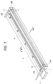
- Fig. 1 is a perspective view which schematically shows an ink jet recording head in accordance with a first embodiment of the present invention.
- Fig. 2 is a cross-sectional view taken along line 2 - 2 in Fig. 1.
- Fig. 3 is a perspective view which schematically illustrates a method for manufacturing an ink jet recording head in accordance with the present invention.
- Fig. 4 is a perspective view which schematically shows the ink jet recording head manufactured by the method represented in Fig. 3.
- Fig. 5 is a side view which shows an ink jet recording head manufactured by another method for manufacturing an ink jet recording head in accordance with the present invention.
- Fig. 6 is an exploded perspective view which shows an ink jet recording head in accordance with another embodiment of the present invention.
- Fig. 7 is a side view which shows an ink jet recording head in accordance with another embodiment of the present invention.
- Fig. 8 is a partly broken perspective view which schematically shows the principal part of an ink jet recording head in accordance with another embodiment of the present invention.
- Fig. 9 is a perspective view which schematically shows the principal part of an ink jet recording apparatus using an ink jet recording head of the present invention.
- Fig. 1 and Fig. 2 are views showing the structure of an ink jet recording head that utilizes thermal energy, in accordance with an embodiment 1 of the present invention.
- Fig. 1 is a perspective view of its head.
- Fig. 2 is a cross-sectional view taken along line 2 - 2 in Fig 1.
- This head is of the so-called full line type, having its discharge ports arranged over a length corresponding to one side of A4-sized recording sheet, for example.
- a reference numeral 1 designates a heater board, that is, a recording element substrate on which electro-thermal transducing elements (discharge heaters) and wiring of Al or the like are formed (not shown) in order to supply electric power to the discharge heaters produced by film formation techniques, as well as driving elements 8 to drive the discharge heaters.
- a reference numeral 3 designates a ceiling plate having liquid paths 3a arranged corresponding to the discharge heaters, and a liquid chamber 3b formed as a recessed portion to supply ink to the liquid paths.
- ink induction inlets 10A and 10B are provided to let in ink to the liquid chamber 3b.
- reference numerals 11A and 11B designate ink supply tubes to supply ink to the head.
- the liquid chamber 3b and the ink induction inlets 10A and 10B are formed by cutting or by means of an etching mold formation.
- a reference numeral 4 designates a base plate, that is, a holding board for holding the heater board 1.
- the ceiling plate 3 On the recording element substrate 1, the ceiling plate 3 is positioned and laminated, and the recording element substrate 1 is positioned and fixed to the base plate 4.
- a circuit board 5 for drawing electric power and electric signals from the outside for discharging ink is positioned exactly with respect to the electric connection pad of the recording element substrate 1.
- a pressure plate 6 is fixed to the base plate 4 by means of screws. Thus the recording element substrate and the base plate are pressed to be in contact with the inclusion of an elastic member 9.
- the recording element substrate 1, the ceiling plate 3, and the base plate 4 are all structured by the same material.
- aluminum (Al), stainless alloy (SUS), copper (Cu) or the like is preferably used.
- Al aluminum
- SUS stainless alloy
- Cu copper
- aluminum and copper referred to in the specification hereof may contain other materials if only such materials reside in them at an impurity level.
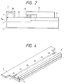
- Fig. 3 is a perspective view which schematically shows a method for manufacturing a recording head.
- Fig. 4 is a perspective view which shows the outer appearance of a recording head manufactured by the method represented in Fig. 3.
- This recording head is formed by laminating a recording element substrate 1a on which discharge energy generating elements are arranged each on opposite sides, a ceiling plate 3a on which liquid chambers are formed on the opposite sides for the provision of ink supply to liquid paths corresponding to the discharge energy generating elements, and a base plate 4a for holding and fixing the recording element substrate 1a. Then, as shown in Fig. 3, the recording head thus formed is cut by means of a blade 12 along the head facing axis A - A.
- two heads are produced at a time, each being formed by the recording element substrate 1, ceiling plate 3, and base plate 4 to provide one body as shown in Fig. 4.
- the recording element substrate 1a, ceiling plate 3a, and base plate 4a being made of a same material, aluminum, for example, are cut at a time. Therefore, no steps are created between the board and plates at all. Also, it is easy to form a smoothly cut uniform surface, that is, the discharge port surface provided with the discharge ports 7.
- Fig. 5 is a side view showing a head.
- the method of manufacture in accordance with the present embodiment is such that the discharge port surfaces of the recording element substrate 1, ceiling plate 3, and base plate 4 are coated with a same water repellent film 134 at a time.
- the recording element substrate 1, ceiling plate 3, and base plate 4 are all formed by a same material, such as aluminum. Therefore, it is possible to provide a water repellent film uniformly using the water repellent film 134 whose close adhesiveness is made all the same. In this respect, for a head manufactured by the method in accordance with the embodiment 2, there are no steps created between the recording element substrate 1, the ceiling plate 3, and the base plate 4 as described above. Therefore, it is possible to coat and form the water repellent film 134 uniformly in a better condition.
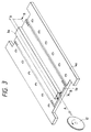
- Fig. 6 is an exploded perspective view showing a recording head in accordance with an embodiment 4 of the present invention.
- a reference numeral 13 designates a recording element substrate on which a plurality of recording elements (heaters) 13a are arranged, and also, there are formed a wiring unit connected with the recording elements, and connecting electrodes 13b provided for the end portion of the wiring unit; 14, a driving element substrate on which driving elements 15 are installed to drive the recording element substrate 13, and connecting electrodes are formed to electrically connect them with the recording element substrate 13; 16, a circuit board to receive electricity received from the outside and input it to the driving element substrate 14; 17, a base plate for use of a driving element substrate to hold and fix the driving element substrate 14 and the circuit board 16, here the driving element substrate 14 and circuit board 16 being connected electrically; and 18, a base plate for use of a recording element substrate to hold and fix the recording element substrate 13.
- the connecting electrodes of the recording element substrate 13 and the driving element substrate 14 are positioned themselves to face each other, and pressed to be in contact with each other by means of a pressure member (not shown). In this way, the electrical connection is made between the recording element substrate 13 and the driving element substrate 14.
- the connecting electrodes are arranged at intervals of several tens to several hundreds ⁇ m. Here, an exact positioning is required.
- the recording element substrate 13, driving element substrate 14, base plate 17, and base plate 18 are all formed by a same material, either one of Al, SUS, Cu, and the like, for example.
- the thermal expansion coefficients of the recording element substrate 13, driving element substrate 14, base plate 17 and base plate 18 are all the same, thus preventing the boards and plates from being damaged by hence eliminating warping, cracking, and other causes due to temperature changes or the like. Also, it is possible to prevent the connecting electrodes of the recording element substrate 13 and driving element substrate 14 from being displaced due to difference in thermal expansion, thus enhancing the reliability of the pressure connection thereof.
- Fig. 7 is a side view which schematically shows a recording head in accordance with an embodiment 5 of the present invention.
- This recording head is an ink jet recording head for which the discharge ports for discharging ink and the ink paths are formed on its recording element substrate, and a ceiling plate is formed with a liquid chamber to supply ink to the ink paths.
- the recording element substrate 13, and the driving element substrate 14 having driving elements 15 arranged thereon are pressed to make the electrical connection.
- the driving elements 15 are connected to the outer side of the head by means of wire bonding through another board 16.
- the recording element substrate 13, ceiling plate 19, driving element substrate 14, base plate 17 and base plate 18 are all structured by one and the same material, such as aluminum. Therefore, it is possible to prevent the ceiling plate 19 from being damaged by warping, deformation, or the like in addition to the effects obtainable by the arrangement as in the embodiment 4.
- the side walls of the ink paths of an ink jet recording head are formed by means of patterning with photo-sensitive resin, while the remaining portions thereof are structured in the same manner as the embodiment 1.
- Fig. 8 is a partly broken perspective view which schematically shows the principal part of the ink jet recording head as described above.
- electrothermal transducing elements 1a and electrodes 1b are arranged on the recording element substrate 1 by means of film formation.
- the walls of liquid paths are produced by patterning with photo-sensitive resin. Then, the ceiling plate 3d is bonded on them.
- a reference mark S designates the discharge port surface where a plurality of discharge ports are arranged.
- the electrothermal transducing elements are energized, the liquid on each electrothermal transducing element is heated rapidly to create an air bubble in the liquid path. By the development and contraction of such air bubble, liquid is discharged from the discharge port 7, thus forming a liquid droplet.
- Fig. 9 is a perspective view which schematically shows the principal part of an ink jet recording apparatus that uses the liquid discharge head 201 of the present invention.
- the liquid discharge head is of a full line type where a plurality of discharge ports are arranged in a length corresponding to the recordable width of a recording medium 150 at intervals of 360 dpi.
- Four heads for four colors, yellow (Y), magenta (M), cyan (C), and black (Bk) are fixed and supported in a holder 202 in parallel to each other at given intervals in the direction indicated by an arrow X in Fig. 9.
- signals are supplied from the head drivers 307 that constitutes means for supplying driving signals.
- Each of the heads is driven in accordance with such signals, respectively.
- each of the four color ink, Y, M, C, and Bk is supplied from each of the ink containers 204a to 204d.
- a reference numeral 204e designates a foaming liquid container in which foaming liquid is stored, and structured to supply it from this container to each of the heads.
- head caps 203a to 203d are arranged below the heads, respectively.
- an ink absorbent such as sponge, is contained to cover the discharge ports of each head in order to protect it when recording is at rest.
- a reference numeral 206 designates a carrier belt constituting feeding means for carrying a recording medium of various types described earlier.
- the carrier belt 206 is drawn around each kind of rollers in a given path, and driven by means of the driving rollers connected to a motor driver 305.
- a pre-processing equipment 251 and a post-processing equipment 252 are arranged, respectively, on the upstream side and downstream side of the recording medium feeding path in order to provide various processes required for the preparation of a recording medium before and after recording.
- the process details of the pre-processing and post-processing are different depending on the kinds of recording media and the kinds of ink to be used for recording, but for such a recording medium as metal, plastic, or ceramics, ultraviolet rays and ozone are irradiated as pre-processing in order to activate the surface of the recording medium, thus enabling ink to enhance its adhesiveness.
- a recording medium is subjected to the generation of static electricity, such as plastic, dust particles easily adhere to the surface thereof because of the electrostatic generation. In some cases, recording does not show good results due to the adhesion of the dust particles. Therefore, as a pre-processing, it is advisable to use an ionizer for the removal of the static electricity from the recording medium to clear off the dust particles therefrom.
- a substance is selected from among alkali substance, water soluble substance, water soluble metallic salt, urea and thiourea, and the substance thus selected is applied to the fabrics with a view to preventing ink from spreading, and also, to enhancing the percentage exhaustion, among others.
- the pre-processing is not necessarily limited to those discussed above, but it may be possible to adopt a process whereby to arrange the temperature of a recording medium to be suitable for recording on such particular medium.
- the post-processing is to conduct a thermal process with respect to the recording medium to which ink has been given, a fixing process to promote the fixation of ink by means of irradiation of ultraviolet rays or the like, and a cleaning process to clean off the processing agents used for the pre-processing but still remaining inactive, among others.
- An ink jet recording head is provided with a recording element substrate having a plurality of discharge energy generating elements for generating energy utilized for discharging ink droplets, a ceiling plate arranged on the recording element substrate having an ink chamber formed to retain ink in the ink paths corresponding to the plurality of discharge energy generating elements, and a base plate for use of a recording element substrate to hold the recording element substrate.
- the recording element substrate, the ceiling plate, and the base plate are structured by the same material, thus preventing the substrate and plates from being damaged by warping, cracking, and other causes due to temperature changes or the like.
Abstract
Description
- The present invention relates to an ink jet recording head, a method for manufacturing such head, and an ink jet recording apparatus. More particularly, the invention relates to an ink jet recording head formed by laminating a substrate having discharge energy generating elements and a plate having a liquid chamber retaining recording liquid (ink), and a method for manufacturing the head, and also, relates to an ink jet recording apparatus using such head.
- Conventionally, there are known various types of ink jet recording heads that discharge recording droplets from the discharge ports. For example, there is the one that discharges recording droplets by the application of pressure changes created in liquid paths by means of deformation of piezoelectric elements or the one in which a pair of electrodes are further provided in addition to the piezoelectric elements in order to cause the recording droplets to deflect, or the one that utilizes thermal energy for discharging recording droplets from the discharge ports by means of heat generating elements arranged in each of ink paths to generate heat rapidly, among others.
- Of these types, the ink jet recording head that uses the method whereby to discharge recording droplets by utilization of thermal energy is given particular attention because, with this method, it is possible to record in high resolution with the arrangement of liquid discharge ports, such as orifices, in high density, which form flying droplets by discharging recording droplets, and to make the entire body compact as a recording head by the effective utilization of the IC technologies and micro-machining techniques whose technical advancement and reliability are enhanced significantly in the semiconductor industrial field in recent years, thus making the elongation and surfacing (two dimensional arrangement) of the head possible, among other advantages, and also, because it is easier to provide a multiple nozzle and implement a highly densified assembling at lower manufacturing costs resulting from the good productivity of the heads when fabricated on a large-scale production.
- Usually, however, the recording head is formed by laminating and fixing the heater board, ceiling plate, and base plate, which are made of different materials. Particularly, for a recording head of a multiple type where the discharge energy generating elements are arranged in a number corresponding to the recording width of a recording medium, the head is subjected to warping, cracking, and other damages occurring due to difference in thermal expansion coefficient of each of the materials used for forming the head, which tends to produce adverse effect due to temperature changes or the like.
- As a result, not only the image quality is degraded, but also, in some cases, there is encountered a problem is encountered that a recording head is destroyed to be no longer usable.
- Also, the discharge ports of a head that discharge recording liquid are often produced by cutting or grinding the portion where discharge ports are formed after the heater board and the ceiling plate are adhesively bonded. Here, since the heater board and the ceiling are made by difference materials having different machinability, it is difficult to process each of the surfaces smoothly to finish them uniformly flat without flash or the like.
- The present invention is designed with a view to solving the problem described above. It is an object of the invention to provide an ink jet recording head for which no warping, cracking, and other damages are caused even when temperature changes, and a method for manufacturing the head, and to provide an ink jet recording apparatus using such head.
- It is another object of the invention to provide an ink jet recording head provided with a recording element substrate having a plurality of discharge energy generating elements for generating energy utilized for discharging ink droplets, a ceiling plate arranged on the recording element substrate having an ink chamber formed to retain ink in the ink paths corresponding to the plurality of discharge energy generating elements, and a base plate for use of a recording element substrate to hold the recording element substrate, this ink jet recording head having the recording element substrate, the ceiling plate, and the base plate, being structured by the same material.
- It is still another object of the invention to provide an ink jet recording head provided with a recording element substrate having a plurality of recording elements arranged thereon, a driving element substrate having driving elements arranged thereon to drive the recording elements, and a base plate for use of a driving element substrate to hold the driving element substrate, the recording element substrate and the driving element substrate being pressed to be in contact to electrically connect them, wherein the recording element substrate, the driving element substrate, and the base plate are structured by the same material.
- It is a further object of the invention to provide a method for manufacturing an ink jet recording head comprising the steps of forming with one and the same material a recording element substrate having a plurality of discharge energy generating elements for generating energy utilized for discharging ink droplets, a ceiling plate arranged on the recording element substrate having an ink chamber formed to retain ink in the ink paths corresponding to the plurality of discharge energy generating elements, and a base plate for use of a recording element substrate to hold the recording element substrate; of laminating the base plate, the recording element substrate, and the ceiling plate so as to allow the ceiling plate and the base plate to nip the recording element substrate; and of forming the discharge ports to discharge ink by cutting the laminated base plate, recording element substrate and ceiling plate at a time.
- It is still a further object of the invention to provide an ink jet recording apparatus comprising an ink jet recording head provided with a recording element substrate having a plurality of discharge energy generating elements for generating energy utilized for discharging ink droplets, a ceiling plate arranged on the recording element substrate having an ink chamber formed to retain ink in the ink paths corresponding to the plurality of discharge energy generating elements, and a base plate for use of a recording element substrate to hold the recording element substrate, this ink jet recording head having the recording element substrate, the ceiling plate, and the base plate, being structured by the same material; and a mounting unit to mount the ink jet recording head.
- It is another object of the invention to provide an ink jet recording apparatus comprising an ink jet recording head provided with a recording element substrate having a plurality of recording elements arranged thereon, a driving element substrate having driving elements arranged thereon to drive the recording elements, and a base plate for use of a driving element substrate to hold the driving element substrate, the recording element substrate and the driving element substrate being pressed to be in contact to electrically connect the recording element substrate and the driving element substrate, this ink jet recording head having the recording element substrate, the driving element substrate, and the base plate being structured by the same material; and a mounting unit to mount the ink jet recording head.
- With the recording element substrate, ceiling plate, and base plate for use of the recording element substrate, which are structured by one and the same material, it is possible to make the thermal expansion coefficients of these board and plates equal, and prevent them from being warped, cracked, or damaged by other causes due to temperature changes or the like.
- Also, the recording element substrate, ceiling plate and base plate are laminated, and then, the portions where discharge ports are formed are cut at a time to produce the discharge ports as well as the discharge port formation surface. As a result, there are no steps being present on the discharge port surface formed by the recording element substrate, ceiling plate and base plate, hence making it easy to form the smooth and flat surface uniformly.
- Also, the structure is formed by a recording element substrate having a plurality of recording elements arranged on it, a driving element substrate having driving elements arranged on it to drive the recording elements, and a base plate used for holding the driving element substrate, wherein the recording element substrate and the driving element substrate are pressed to be in contact to electrically connect them, and at the same time, the recording element substrate, the driving element substrate, and the base plate are made by the same material. Therefore, it is possible to improve the drawbacks of the electrical connection between these boards due to temperature changes or the like, such as being encountered in the conventional art.
- Other objectives and advantages besides those discussed above will be apparent to those skilled in the art from the description of a preferred embodiment of the invention which follow. In the description, reference is made to accompanying drawings, which form a part hereof, and which illustrate an example of the invention. Such example, however, is not exhaustive of the various embodiments of the invention, and therefore reference is made to the claims which follow the description for determining the scope of the invention.
- Fig. 1 is a perspective view which schematically shows an ink jet recording head in accordance with a first embodiment of the present invention.
- Fig. 2 is a cross-sectional view taken along line 2 - 2 in Fig. 1.
- Fig. 3 is a perspective view which schematically illustrates a method for manufacturing an ink jet recording head in accordance with the present invention.
- Fig. 4 is a perspective view which schematically shows the ink jet recording head manufactured by the method represented in Fig. 3.
- Fig. 5 is a side view which shows an ink jet recording head manufactured by another method for manufacturing an ink jet recording head in accordance with the present invention.
- Fig. 6 is an exploded perspective view which shows an ink jet recording head in accordance with another embodiment of the present invention.
- Fig. 7 is a side view which shows an ink jet recording head in accordance with another embodiment of the present invention.
- Fig. 8 is a partly broken perspective view which schematically shows the principal part of an ink jet recording head in accordance with another embodiment of the present invention.
- Fig. 9 is a perspective view which schematically shows the principal part of an ink jet recording apparatus using an ink jet recording head of the present invention.
- Hereinafter, with reference to the accompanying drawings, the description will be made of the embodiments in accordance with the present invention.
- Fig. 1 and Fig. 2 are views showing the structure of an ink jet recording head that utilizes thermal energy, in accordance with an
embodiment 1 of the present invention. Fig. 1 is a perspective view of its head. Fig. 2 is a cross-sectional view taken along line 2 - 2 in Fig 1. This head is of the so-called full line type, having its discharge ports arranged over a length corresponding to one side of A4-sized recording sheet, for example. - In Fig. 1 and Fig. 2, a
reference numeral 1 designates a heater board, that is, a recording element substrate on which electro-thermal transducing elements (discharge heaters) and wiring of Al or the like are formed (not shown) in order to supply electric power to the discharge heaters produced by film formation techniques, as well as drivingelements 8 to drive the discharge heaters. Areference numeral 3 designates a ceiling plate havingliquid paths 3a arranged corresponding to the discharge heaters, and aliquid chamber 3b formed as a recessed portion to supply ink to the liquid paths. For theceiling plate 3,ink induction inlets liquid chamber 3b. Here,reference numerals liquid chamber 3b and theink induction inlets reference numeral 4 designates a base plate, that is, a holding board for holding theheater board 1. - On the
recording element substrate 1, theceiling plate 3 is positioned and laminated, and therecording element substrate 1 is positioned and fixed to thebase plate 4. Acircuit board 5 for drawing electric power and electric signals from the outside for discharging ink is positioned exactly with respect to the electric connection pad of therecording element substrate 1. Apressure plate 6 is fixed to thebase plate 4 by means of screws. Thus the recording element substrate and the base plate are pressed to be in contact with the inclusion of anelastic member 9. - In accordance with the present embodiment of the recording head, the
recording element substrate 1, theceiling plate 3, and thebase plate 4 are all structured by the same material. For such material, aluminum (Al), stainless alloy (SUS), copper (Cu) or the like is preferably used. Of these materials, it is particularly preferable to use aluminum from the viewpoint of its heat radiation and machinability. Since one and the same material is used, the heat expansion coefficients of therecording element substrate 1,ceiling plate 3, andbase plate 4 are all the same. As a result, there is no possibility that the board and plates are warped, cracked, or damaged by other causes due to temperature changes or the like. In this respect, aluminum and copper referred to in the specification hereof may contain other materials if only such materials reside in them at an impurity level. - With reference to Fig. 3 and Fig. 4, the description will be made of a method for manufacturing an ink jet recording head in accordance with the present invention.
- Fig. 3 is a perspective view which schematically shows a method for manufacturing a recording head. Fig. 4 is a perspective view which shows the outer appearance of a recording head manufactured by the method represented in Fig. 3.
- This recording head is formed by laminating a
recording element substrate 1a on which discharge energy generating elements are arranged each on opposite sides, aceiling plate 3a on which liquid chambers are formed on the opposite sides for the provision of ink supply to liquid paths corresponding to the discharge energy generating elements, and abase plate 4a for holding and fixing therecording element substrate 1a. Then, as shown in Fig. 3, the recording head thus formed is cut by means of ablade 12 along the head facing axis A - A. - By means of this process, two heads are produced at a time, each being formed by the
recording element substrate 1,ceiling plate 3, andbase plate 4 to provide one body as shown in Fig. 4. - In accordance with the present embodiment, the
recording element substrate 1a,ceiling plate 3a, andbase plate 4a, being made of a same material, aluminum, for example, are cut at a time. Therefore, no steps are created between the board and plates at all. Also, it is easy to form a smoothly cut uniform surface, that is, the discharge port surface provided with thedischarge ports 7. - As a result, it is possible to minimize the adhesion of ink droplets to the discharge port surface. At the same time, it is possible to operate wiping or the like smoothly and effectively in order to remove ink droplets and dust particles adhering to the discharge port surface.
- With reference to Fig. 5, the description will be made of a method for manufacturing an ink jet recording head in accordance with another embodiment of the present invention. Fig. 5 is a side view showing a head.
- The method of manufacture in accordance with the present embodiment is such that the discharge port surfaces of the
recording element substrate 1,ceiling plate 3, andbase plate 4 are coated with a samewater repellent film 134 at a time. - In this case, the
recording element substrate 1,ceiling plate 3, andbase plate 4 are all formed by a same material, such as aluminum. Therefore, it is possible to provide a water repellent film uniformly using thewater repellent film 134 whose close adhesiveness is made all the same. In this respect, for a head manufactured by the method in accordance with theembodiment 2, there are no steps created between therecording element substrate 1, theceiling plate 3, and thebase plate 4 as described above. Therefore, it is possible to coat and form thewater repellent film 134 uniformly in a better condition. - Fig. 6 is an exploded perspective view showing a recording head in accordance with an
embodiment 4 of the present invention. - In Fig. 6, a
reference numeral 13 designates a recording element substrate on which a plurality of recording elements (heaters) 13a are arranged, and also, there are formed a wiring unit connected with the recording elements, and connectingelectrodes 13b provided for the end portion of the wiring unit; 14, a driving element substrate on which drivingelements 15 are installed to drive therecording element substrate 13, and connecting electrodes are formed to electrically connect them with therecording element substrate 13; 16, a circuit board to receive electricity received from the outside and input it to the drivingelement substrate 14; 17, a base plate for use of a driving element substrate to hold and fix thedriving element substrate 14 and thecircuit board 16, here the drivingelement substrate 14 andcircuit board 16 being connected electrically; and 18, a base plate for use of a recording element substrate to hold and fix therecording element substrate 13. - Then, the connecting electrodes of the
recording element substrate 13 and the drivingelement substrate 14 are positioned themselves to face each other, and pressed to be in contact with each other by means of a pressure member (not shown). In this way, the electrical connection is made between therecording element substrate 13 and the drivingelement substrate 14. The connecting electrodes are arranged at intervals of several tens to several hundreds µm. Here, an exact positioning is required. - With respect to the structure arranged as described above in accordance with the present embodiment, the
recording element substrate 13, drivingelement substrate 14,base plate 17, andbase plate 18 are all formed by a same material, either one of Al, SUS, Cu, and the like, for example. - As a result, the thermal expansion coefficients of the
recording element substrate 13, drivingelement substrate 14,base plate 17 andbase plate 18 are all the same, thus preventing the boards and plates from being damaged by hence eliminating warping, cracking, and other causes due to temperature changes or the like. Also, it is possible to prevent the connecting electrodes of therecording element substrate 13 and drivingelement substrate 14 from being displaced due to difference in thermal expansion, thus enhancing the reliability of the pressure connection thereof. - Fig. 7 is a side view which schematically shows a recording head in accordance with an
embodiment 5 of the present invention. - This recording head is an ink jet recording head for which the discharge ports for discharging ink and the ink paths are formed on its recording element substrate, and a ceiling plate is formed with a liquid chamber to supply ink to the ink paths.
- Also, in the same manner as the
embodiment 4, therecording element substrate 13, and the drivingelement substrate 14 havingdriving elements 15 arranged thereon are pressed to make the electrical connection. Here, the drivingelements 15 are connected to the outer side of the head by means of wire bonding through anotherboard 16. - In accordance with the present embodiment, too, the
recording element substrate 13,ceiling plate 19, drivingelement substrate 14,base plate 17 andbase plate 18 are all structured by one and the same material, such as aluminum. Therefore, it is possible to prevent theceiling plate 19 from being damaged by warping, deformation, or the like in addition to the effects obtainable by the arrangement as in theembodiment 4. - Also, it is possible to cut the
recording element substrate 13,ceiling plate 19, andbase plate 18 at a time. Therefore, workability is improved. At the same time, the uniform smoothness of the discharge port surface is obtained in a better condition. - In accordance with the present embodiment, the side walls of the ink paths of an ink jet recording head are formed by means of patterning with photo-sensitive resin, while the remaining portions thereof are structured in the same manner as the
embodiment 1. - Fig. 8 is a partly broken perspective view which schematically shows the principal part of the ink jet recording head as described above. Through the semi-conductor fabrication steps, such as etching, deposition, and sputtering,
electrothermal transducing elements 1a andelectrodes 1b are arranged on therecording element substrate 1 by means of film formation. On the recording element substrate thus prepared, the walls of liquid paths are produced by patterning with photo-sensitive resin. Then, theceiling plate 3d is bonded on them. - Liquid supplied to the
common liquid chamber 3b is supplied into theliquid paths 3a by the application of the so-called capillary phenomenon and forms meniscus at thedischarge ports 7 located at the leading end of the liquid paths. Hence the discharging liquid is held stably. A reference mark S designates the discharge port surface where a plurality of discharge ports are arranged. Here, when the electrothermal transducing elements are energized, the liquid on each electrothermal transducing element is heated rapidly to create an air bubble in the liquid path. By the development and contraction of such air bubble, liquid is discharged from thedischarge port 7, thus forming a liquid droplet. With the structure described above, it is possible to form an ink jet recording head having 128 or 256 discharge ports in a discharge port density of 16 nozzles/mm or, further, having the multiple nozzles where the discharge ports are arranged to cover the entire recording width. - Fig. 9 is a perspective view which schematically shows the principal part of an ink jet recording apparatus that uses the liquid discharge head 201 of the present invention. In accordance with the present embodiment, the liquid discharge head is of a full line type where a plurality of discharge ports are arranged in a length corresponding to the recordable width of a recording medium 150 at intervals of 360 dpi. Four heads for four colors, yellow (Y), magenta (M), cyan (C), and black (Bk), are fixed and supported in a
holder 202 in parallel to each other at given intervals in the direction indicated by an arrow X in Fig. 9. To these heads, signals are supplied from the head drivers 307 that constitutes means for supplying driving signals. Each of the heads is driven in accordance with such signals, respectively. - To each of the heads, each of the four color ink, Y, M, C, and Bk, is supplied from each of the
ink containers 204a to 204d. In this respect, areference numeral 204e designates a foaming liquid container in which foaming liquid is stored, and structured to supply it from this container to each of the heads. - Also,
head caps 203a to 203d are arranged below the heads, respectively. In each of the caps, an ink absorbent, such as sponge, is contained to cover the discharge ports of each head in order to protect it when recording is at rest. - A
reference numeral 206 designates a carrier belt constituting feeding means for carrying a recording medium of various types described earlier. Thecarrier belt 206 is drawn around each kind of rollers in a given path, and driven by means of the driving rollers connected to amotor driver 305. - In accordance with the ink jet recording system of the present embodiment, a
pre-processing equipment 251 and apost-processing equipment 252 are arranged, respectively, on the upstream side and downstream side of the recording medium feeding path in order to provide various processes required for the preparation of a recording medium before and after recording. - The process details of the pre-processing and post-processing are different depending on the kinds of recording media and the kinds of ink to be used for recording, but for such a recording medium as metal, plastic, or ceramics, ultraviolet rays and ozone are irradiated as pre-processing in order to activate the surface of the recording medium, thus enabling ink to enhance its adhesiveness. Also, if the recording medium is subjected to the generation of static electricity, such as plastic, dust particles easily adhere to the surface thereof because of the electrostatic generation. In some cases, recording does not show good results due to the adhesion of the dust particles. Therefore, as a pre-processing, it is advisable to use an ionizer for the removal of the static electricity from the recording medium to clear off the dust particles therefrom. Also, when fabrics are used as a recording medium, it is advisable to conduct a pre-processing in which a substance is selected from among alkali substance, water soluble substance, water soluble metallic salt, urea and thiourea, and the substance thus selected is applied to the fabrics with a view to preventing ink from spreading, and also, to enhancing the percentage exhaustion, among others. The pre-processing is not necessarily limited to those discussed above, but it may be possible to adopt a process whereby to arrange the temperature of a recording medium to be suitable for recording on such particular medium.
- Meanwhile, the post-processing is to conduct a thermal process with respect to the recording medium to which ink has been given, a fixing process to promote the fixation of ink by means of irradiation of ultraviolet rays or the like, and a cleaning process to clean off the processing agents used for the pre-processing but still remaining inactive, among others.
- As described above, in accordance with the present invention, it is easy to obtain and manufacture a highly reliable ink jet recording head capable of obtaining high quality images at all times by the provision of a uniformly smooth discharge port surface, which is not damaged by warping, cracking, or some other causes due to temperature changes or the like.
- An ink jet recording head is provided with a recording element substrate having a plurality of discharge energy generating elements for generating energy utilized for discharging ink droplets, a ceiling plate arranged on the recording element substrate having an ink chamber formed to retain ink in the ink paths corresponding to the plurality of discharge energy generating elements, and a base plate for use of a recording element substrate to hold the recording element substrate. For this ink jet recording head, the recording element substrate, the ceiling plate, and the base plate are structured by the same material, thus preventing the substrate and plates from being damaged by warping, cracking, and other causes due to temperature changes or the like.
Claims (17)
- An ink jet recording head provided with a recording element substrate having a plurality of discharge energy generating elements for generating energy utilized for discharging ink droplets, a ceiling plate arranged on said recording element substrate having an ink chamber formed to retain ink in the ink paths corresponding to said plurality of discharge energy generating elements, and a base plate for use of a recording element substrate to hold said recording element substrate, said ink jet recording head having said recording element substrate, said ceiling plate, and said base plate, being structured by the same material.
- An ink jet recording head according to Claim 1, wherein one and the same material used for said recording element substrate, said ceiling plate, and said base plate is either one of the materials selected from aluminum, stainless alloy, and copper.
- An ink jet recording head according to Claim 1, wherein the side wall portions of said ink paths are structured by resin.
- An ink jet recording head according to Claim 1, wherein a water repellent film is provided for the entire surface of said recording element substrate, said ceiling plate, and said base plate including the discharge ports for discharging ink.
- An ink jet recording head provided with a recording element substrate having a plurality of recording elements arranged thereon, a driving element substrate having driving elements arranged thereon to drive said recording elements, and a base plate for use of a driving element substrate to hold said driving element substrate, said recording element substrate and said driving element substrate being pressed to be in contact to electrically connect said recording element substrate and said driving element substrate, wherein said recording element substrate, said driving element substrate, and said base plate are structured by the same material.
- An ink jet recording head according to Claim 5, wherein a ceiling plate having an ink chamber formed thereon to retain ink to be supplied to said ink paths conductively connected with discharge ports for discharging ink is arranged on said recording element substrate, and said ceiling plate is also structured by the one and same material structuring said recording element substrate, said driving element substrate, and said base plate.
- An ink jet recording head according to Claim 5, wherein a base plate for use of a recording element substrate is provided to hold said recording element substrate, and said base plate is also structured by said one and same material.
- An ink jet recording head according to Claim 5, wherein said one and same material is either one of the materials selected from aluminum, stainless alloy, and copper.
- An ink jet recording head according to Claim 5, wherein the side wall portions of the ink paths are structured by resin.
- An ink jet recording head according to Claim 1, wherein many numbers of discharge ports for discharging ink are arranged corresponding to the width of a recording medium used for recording.
- An ink jet recording head according to Claim 1, wherein said recording elements are electrothermal transducing elements for generating thermal energy.
- A method for manufacturing an ink jet recording head comprising the following steps of:forming with the same material a recording element substrate having a plurality of discharge energy generating elements for generating energy utilized for discharging ink droplets, a ceiling plate arranged on said recording element substrate having an ink chamber formed to retain ink in the ink paths corresponding to said plurality of discharge energy generating elements, and a base plate for use of a recording element substrate to hold said recording element substrate;laminating said base plate, said recording element substrate, and said ceiling plate so as to allow said ceiling plate and said base plate to nip said recording element substrate; andforming the discharge ports for discharging ink by cutting said laminated base plate, recording element substrate and ceiling plate at a time.
- An ink jet recording apparatus comprising:an ink jet recording head provided with a recording element substrate having a plurality of discharge energy generating elements for generating energy utilized for discharging ink droplets, a ceiling plate arranged on said recording element substrate having an ink chamber formed to retain ink in the ink paths corresponding to said plurality of discharge energy generating elements, and a base plate for use of a recording element substrate to hold said recording element substrate, said recording head having said recording element substrate, said ceiling plate, and said base plate, being structured by the same material; anda mounting unit to mount the ink jet recording head.
- An ink jet recording apparatus comprising:an ink jet recording head provided with a recording element substrate having a plurality of recording elements arranged thereon, a driving element substrate having driving elements arranged thereon to drive said recording elements, and a base plate for use of a driving element substrate to hold said driving element substrate, said recording element substrate and said driving element substrate being pressed to be in contact to electrically connect said recording element substrate and said driving element substrate, and said recording element substrate, said driving element substrate, and said base plate being structured by the same material; anda mounting unit to mount the ink jet recording head.
- An ink jet recording head according to Claim 6, wherein a base plate for use of a recording element substrate is provided to hold said recording element substrate, and said base plate is also structured by said one and same material.
- An ink jet recording head according to Claim 5, wherein many numbers of discharge ports for discharging ink are arranged corresponding to the width of a recording medium used for recording.
- An ink jet recording head according to Claim 5, wherein said recording elements are electrothermal transducing elements for generating thermal energy.
Applications Claiming Priority (3)
| Application Number | Priority Date | Filing Date | Title |
|---|---|---|---|
| JP141606/95 | 1995-06-08 | ||
| JP14160695 | 1995-06-08 | ||
| JP14160695 | 1995-06-08 |
Publications (3)
| Publication Number | Publication Date |
|---|---|
| EP0747222A2 true EP0747222A2 (en) | 1996-12-11 |
| EP0747222A3 EP0747222A3 (en) | 1997-07-30 |
| EP0747222B1 EP0747222B1 (en) | 2001-04-25 |
Family
ID=15295931
Family Applications (1)
| Application Number | Title | Priority Date | Filing Date |
|---|---|---|---|
| EP96109217A Expired - Lifetime EP0747222B1 (en) | 1995-06-08 | 1996-06-07 | Ink jet recording head, method for manufacturing such head, and ink jet recording apparatus |
Country Status (4)
| Country | Link |
|---|---|
| US (1) | US6113214A (en) |
| EP (1) | EP0747222B1 (en) |
| JP (1) | JPH0952365A (en) |
| DE (1) | DE69612588T2 (en) |
Cited By (1)
| Publication number | Priority date | Publication date | Assignee | Title |
|---|---|---|---|---|
| US5902492A (en) * | 1995-08-09 | 1999-05-11 | Canon Kabushiki Kaisha | Liquid jet recording head manufacturing method by anisotropic etching |
Families Citing this family (6)
| Publication number | Priority date | Publication date | Assignee | Title |
|---|---|---|---|---|
| JPH11198375A (en) * | 1998-01-12 | 1999-07-27 | Canon Inc | Ink jet recording head and recorder |
| US6428145B1 (en) * | 1998-12-17 | 2002-08-06 | Hewlett-Packard Company | Wide-array inkjet printhead assembly with internal electrical routing system |
| US6705691B2 (en) | 2000-01-14 | 2004-03-16 | Canon Kabushiki Kaisha | Ink-jet printing method and ink-jet printer |
| JP4280574B2 (en) * | 2002-07-10 | 2009-06-17 | キヤノン株式会社 | Method for manufacturing liquid discharge head |
| US7775638B2 (en) * | 2004-07-22 | 2010-08-17 | Canon Kabushiki Kaisha | Ink jet recording head and recording apparatus |
| JP5388615B2 (en) * | 2009-02-06 | 2014-01-15 | キヤノン株式会社 | Inkjet recording head |
Citations (6)
| Publication number | Priority date | Publication date | Assignee | Title |
|---|---|---|---|---|
| US4663640A (en) * | 1984-07-20 | 1987-05-05 | Canon Kabushiki Kaisha | Recording head |
| EP0347856A1 (en) * | 1988-06-21 | 1989-12-27 | Canon Kabushiki Kaisha | Ink jet recording head |
| EP0442706A2 (en) * | 1990-02-13 | 1991-08-21 | Canon Kabushiki Kaisha | Electrically conductive sheet, recording head using the same and recording apparatus |
| JPH0478539A (en) * | 1990-07-21 | 1992-03-12 | Fuji Xerox Co Ltd | Thermal ink jet head |
| EP0602021A2 (en) * | 1988-10-31 | 1994-06-15 | Canon Kabushiki Kaisha | Ink jet head and manufacturing method thereof, discharge opening plate for head and manufacturing method thereof, and ink jet apparatus with ink jet head |
| EP0605006A2 (en) * | 1993-01-01 | 1994-07-06 | Canon Kabushiki Kaisha | Liquid ejecting head, liquid ejecting apparatus and method of producing said liquid ejecting head |
Family Cites Families (8)
| Publication number | Priority date | Publication date | Assignee | Title |
|---|---|---|---|---|
| US4499480A (en) * | 1981-10-13 | 1985-02-12 | Canon Kabushiki Kaisha | Liquid jet recording device |
| JPH0284343A (en) * | 1988-03-16 | 1990-03-26 | Canon Inc | Liquid jet recording head |
| US5243363A (en) * | 1988-07-22 | 1993-09-07 | Canon Kabushiki Kaisha | Ink-jet recording head having bump-shaped electrode and protective layer providing structural support |
| JPH02204048A (en) * | 1989-02-03 | 1990-08-14 | Canon Inc | Ink jet recording head and manufacture thereof |
| US5220345A (en) * | 1989-03-31 | 1993-06-15 | Canon Kabushiki Kaisha | Ink jet recording apparatus |
| US5451989A (en) * | 1989-07-28 | 1995-09-19 | Canon Kabushiki Kaisha | Ink jet recording apparatus with a heat pipe for temperature stabilization |
| JP2752486B2 (en) * | 1989-12-29 | 1998-05-18 | キヤノン株式会社 | INK JET PRINT HEAD, INSPECTION METHOD THEREOF, AND INK JET PRINTING APPARATUS |
| ES2073670T3 (en) * | 1990-02-02 | 1995-08-16 | Canon Kk | APPARATUS FOR PRINTING WITH INK JETS AND HEAD FOR PRINTING WITH INK JETS. |
-
1996
- 1996-06-03 JP JP8140160A patent/JPH0952365A/en active Pending
- 1996-06-03 US US08/657,077 patent/US6113214A/en not_active Expired - Fee Related
- 1996-06-07 EP EP96109217A patent/EP0747222B1/en not_active Expired - Lifetime
- 1996-06-07 DE DE69612588T patent/DE69612588T2/en not_active Expired - Fee Related
Patent Citations (6)
| Publication number | Priority date | Publication date | Assignee | Title |
|---|---|---|---|---|
| US4663640A (en) * | 1984-07-20 | 1987-05-05 | Canon Kabushiki Kaisha | Recording head |
| EP0347856A1 (en) * | 1988-06-21 | 1989-12-27 | Canon Kabushiki Kaisha | Ink jet recording head |
| EP0602021A2 (en) * | 1988-10-31 | 1994-06-15 | Canon Kabushiki Kaisha | Ink jet head and manufacturing method thereof, discharge opening plate for head and manufacturing method thereof, and ink jet apparatus with ink jet head |
| EP0442706A2 (en) * | 1990-02-13 | 1991-08-21 | Canon Kabushiki Kaisha | Electrically conductive sheet, recording head using the same and recording apparatus |
| JPH0478539A (en) * | 1990-07-21 | 1992-03-12 | Fuji Xerox Co Ltd | Thermal ink jet head |
| EP0605006A2 (en) * | 1993-01-01 | 1994-07-06 | Canon Kabushiki Kaisha | Liquid ejecting head, liquid ejecting apparatus and method of producing said liquid ejecting head |
Non-Patent Citations (1)
| Title |
|---|
| PATENT ABSTRACTS OF JAPAN vol. 016, no. 290 (M-1272), 26 June 1992 & JP 04 078539 A (FUJI XEROX CO LTD), 12 March 1992, * |
Cited By (1)
| Publication number | Priority date | Publication date | Assignee | Title |
|---|---|---|---|---|
| US5902492A (en) * | 1995-08-09 | 1999-05-11 | Canon Kabushiki Kaisha | Liquid jet recording head manufacturing method by anisotropic etching |
Also Published As
| Publication number | Publication date |
|---|---|
| DE69612588D1 (en) | 2001-05-31 |
| DE69612588T2 (en) | 2001-09-06 |
| JPH0952365A (en) | 1997-02-25 |
| US6113214A (en) | 2000-09-05 |
| EP0747222B1 (en) | 2001-04-25 |
| EP0747222A3 (en) | 1997-07-30 |
Similar Documents
| Publication | Publication Date | Title |
|---|---|---|
| KR101137643B1 (en) | Print head with thin membrane | |
| EP2540503B1 (en) | Liquid jet head, liquid jet apparatus, and method of manufacturing liquid jet head | |
| US6241340B1 (en) | Ink-jet recording head, process for producing the head and ink-jet recording apparatus employing the head | |
| US6409315B2 (en) | Substrate for use of an ink jet recording head, an ink jet head using such substrate, a method for driving such substrate, and an jet head cartridge, and a liquid discharge apparatus | |
| US6186616B1 (en) | Ink jet head having an improved orifice plate, a method for manufacturing such ink jet heads, and an ink jet apparatus provided with such ink jet head | |
| EP0920998A2 (en) | Liquid discharge head, liquid discharge method, head cartridge and liquid discharge device | |
| US6530641B2 (en) | Liquid discharge head unit, head cartridge, and method for manufacturing liquid discharge head unit | |
| KR100744451B1 (en) | Droplet ejection apparatus | |
| EP0707965B1 (en) | Liquid jet head substrate, liquid jet head using same and liquid jet apparatus using same | |
| JPH1058685A (en) | Ink jet print head having channels arranged on surface in silicon | |
| EP0747222B1 (en) | Ink jet recording head, method for manufacturing such head, and ink jet recording apparatus | |
| JP2006256029A (en) | Inkjet head and manufacturing method and image forming device using the inkjet head | |
| US6808252B2 (en) | Ink jet recording head and manufacturing method therefor | |
| US6137506A (en) | Ink jet recording head with a plurality of orifice plates | |
| US7806518B2 (en) | Inkjet recording head and inkjet recording apparatus | |
| JP3756506B1 (en) | Ink jet head and manufacturing method thereof | |
| JP2005306021A (en) | Manufacturing method for discharge head and discharge head | |
| JP3260546B2 (en) | Substrate for inkjet head, inkjet head, method of manufacturing substrate for inkjet head, and method of manufacturing inkjet head | |
| JPH03187753A (en) | Recorder | |
| JP2023157672A (en) | Liquid discharge head and recording device | |
| JP2003246064A (en) | Inkjet recording head and its manufacturing method | |
| JP2001071492A (en) | Liqiud-jet recording head and its manufacture | |
| JP2000117976A (en) | Printing head and manufacture thereof | |
| JP2007022038A (en) | Inkjet recording head | |
| JPH08267737A (en) | Ink jet device |
Legal Events
| Date | Code | Title | Description |
|---|---|---|---|
| PUAI | Public reference made under article 153(3) epc to a published international application that has entered the european phase |
Free format text: ORIGINAL CODE: 0009012 |
|
| AK | Designated contracting states |
Kind code of ref document: A2 Designated state(s): DE FR GB IT |
|
| PUAL | Search report despatched |
Free format text: ORIGINAL CODE: 0009013 |
|
| AK | Designated contracting states |
Kind code of ref document: A3 Designated state(s): DE FR GB IT |
|
| 17P | Request for examination filed |
Effective date: 19971216 |
|
| GRAG | Despatch of communication of intention to grant |
Free format text: ORIGINAL CODE: EPIDOS AGRA |
|
| 17Q | First examination report despatched |
Effective date: 19991104 |
|
| GRAG | Despatch of communication of intention to grant |
Free format text: ORIGINAL CODE: EPIDOS AGRA |
|
| GRAG | Despatch of communication of intention to grant |
Free format text: ORIGINAL CODE: EPIDOS AGRA |
|
| GRAH | Despatch of communication of intention to grant a patent |
Free format text: ORIGINAL CODE: EPIDOS IGRA |
|
| GRAH | Despatch of communication of intention to grant a patent |
Free format text: ORIGINAL CODE: EPIDOS IGRA |
|
| GRAA | (expected) grant |
Free format text: ORIGINAL CODE: 0009210 |
|
| AK | Designated contracting states |
Kind code of ref document: B1 Designated state(s): DE FR GB IT |
|
| PG25 | Lapsed in a contracting state [announced via postgrant information from national office to epo] |
Ref country code: IT Free format text: LAPSE BECAUSE OF FAILURE TO SUBMIT A TRANSLATION OF THE DESCRIPTION OR TO PAY THE FEE WITHIN THE PRE;WARNING: LAPSES OF ITALIAN PATENTS WITH EFFECTIVE DATE BEFORE 2007 MAY HAVE OCCURRED AT ANY TIME BEFORE 2007. THE CORRECT EFFECTIVE DATE MAY BE DIFFERENT FROM THE ONE RECORDED.SCRIBED TIME-LIMIT Effective date: 20010425 Ref country code: FR Free format text: LAPSE BECAUSE OF FAILURE TO SUBMIT A TRANSLATION OF THE DESCRIPTION OR TO PAY THE FEE WITHIN THE PRESCRIBED TIME-LIMIT Effective date: 20010425 |
|
| REF | Corresponds to: |
Ref document number: 69612588 Country of ref document: DE Date of ref document: 20010531 |
|
| EN | Fr: translation not filed | ||
| REG | Reference to a national code |
Ref country code: GB Ref legal event code: IF02 |
|
| PLBE | No opposition filed within time limit |
Free format text: ORIGINAL CODE: 0009261 |
|
| STAA | Information on the status of an ep patent application or granted ep patent |
Free format text: STATUS: NO OPPOSITION FILED WITHIN TIME LIMIT |
|
| 26N | No opposition filed | ||
| PGFP | Annual fee paid to national office [announced via postgrant information from national office to epo] |
Ref country code: DE Payment date: 20070531 Year of fee payment: 12 |
|
| PGFP | Annual fee paid to national office [announced via postgrant information from national office to epo] |
Ref country code: GB Payment date: 20070606 Year of fee payment: 12 |
|
| GBPC | Gb: european patent ceased through non-payment of renewal fee |
Effective date: 20080607 |
|
| PG25 | Lapsed in a contracting state [announced via postgrant information from national office to epo] |
Ref country code: DE Free format text: LAPSE BECAUSE OF NON-PAYMENT OF DUE FEES Effective date: 20090101 |
|
| PG25 | Lapsed in a contracting state [announced via postgrant information from national office to epo] |
Ref country code: GB Free format text: LAPSE BECAUSE OF NON-PAYMENT OF DUE FEES Effective date: 20080607 |