EP0747025B1 - Low wear artificial spinal disc - Google Patents
Low wear artificial spinal disc Download PDFInfo
- Publication number
- EP0747025B1 EP0747025B1 EP96304205A EP96304205A EP0747025B1 EP 0747025 B1 EP0747025 B1 EP 0747025B1 EP 96304205 A EP96304205 A EP 96304205A EP 96304205 A EP96304205 A EP 96304205A EP 0747025 B1 EP0747025 B1 EP 0747025B1
- Authority
- EP
- European Patent Office
- Prior art keywords
- spinal disc
- artificial spinal
- component
- disc
- vertebrae
- Prior art date
- Legal status (The legal status is an assumption and is not a legal conclusion. Google has not performed a legal analysis and makes no representation as to the accuracy of the status listed.)
- Expired - Lifetime
Links
Images


Classifications
-
- A—HUMAN NECESSITIES
- A61—MEDICAL OR VETERINARY SCIENCE; HYGIENE
- A61F—FILTERS IMPLANTABLE INTO BLOOD VESSELS; PROSTHESES; DEVICES PROVIDING PATENCY TO, OR PREVENTING COLLAPSING OF, TUBULAR STRUCTURES OF THE BODY, e.g. STENTS; ORTHOPAEDIC, NURSING OR CONTRACEPTIVE DEVICES; FOMENTATION; TREATMENT OR PROTECTION OF EYES OR EARS; BANDAGES, DRESSINGS OR ABSORBENT PADS; FIRST-AID KITS
- A61F2/00—Filters implantable into blood vessels; Prostheses, i.e. artificial substitutes or replacements for parts of the body; Appliances for connecting them with the body; Devices providing patency to, or preventing collapsing of, tubular structures of the body, e.g. stents
- A61F2/02—Prostheses implantable into the body
- A61F2/30—Joints
- A61F2/44—Joints for the spine, e.g. vertebrae, spinal discs
- A61F2/442—Intervertebral or spinal discs, e.g. resilient
- A61F2/4425—Intervertebral or spinal discs, e.g. resilient made of articulated components
-
- A—HUMAN NECESSITIES
- A61—MEDICAL OR VETERINARY SCIENCE; HYGIENE
- A61L—METHODS OR APPARATUS FOR STERILISING MATERIALS OR OBJECTS IN GENERAL; DISINFECTION, STERILISATION OR DEODORISATION OF AIR; CHEMICAL ASPECTS OF BANDAGES, DRESSINGS, ABSORBENT PADS OR SURGICAL ARTICLES; MATERIALS FOR BANDAGES, DRESSINGS, ABSORBENT PADS OR SURGICAL ARTICLES
- A61L27/00—Materials for grafts or prostheses or for coating grafts or prostheses
- A61L27/02—Inorganic materials
- A61L27/04—Metals or alloys
- A61L27/045—Cobalt or cobalt alloys
-
- A—HUMAN NECESSITIES
- A61—MEDICAL OR VETERINARY SCIENCE; HYGIENE
- A61F—FILTERS IMPLANTABLE INTO BLOOD VESSELS; PROSTHESES; DEVICES PROVIDING PATENCY TO, OR PREVENTING COLLAPSING OF, TUBULAR STRUCTURES OF THE BODY, e.g. STENTS; ORTHOPAEDIC, NURSING OR CONTRACEPTIVE DEVICES; FOMENTATION; TREATMENT OR PROTECTION OF EYES OR EARS; BANDAGES, DRESSINGS OR ABSORBENT PADS; FIRST-AID KITS
- A61F2/00—Filters implantable into blood vessels; Prostheses, i.e. artificial substitutes or replacements for parts of the body; Appliances for connecting them with the body; Devices providing patency to, or preventing collapsing of, tubular structures of the body, e.g. stents
- A61F2/02—Prostheses implantable into the body
- A61F2/30—Joints
- A61F2/30767—Special external or bone-contacting surface, e.g. coating for improving bone ingrowth
-
- A—HUMAN NECESSITIES
- A61—MEDICAL OR VETERINARY SCIENCE; HYGIENE
- A61F—FILTERS IMPLANTABLE INTO BLOOD VESSELS; PROSTHESES; DEVICES PROVIDING PATENCY TO, OR PREVENTING COLLAPSING OF, TUBULAR STRUCTURES OF THE BODY, e.g. STENTS; ORTHOPAEDIC, NURSING OR CONTRACEPTIVE DEVICES; FOMENTATION; TREATMENT OR PROTECTION OF EYES OR EARS; BANDAGES, DRESSINGS OR ABSORBENT PADS; FIRST-AID KITS
- A61F2/00—Filters implantable into blood vessels; Prostheses, i.e. artificial substitutes or replacements for parts of the body; Appliances for connecting them with the body; Devices providing patency to, or preventing collapsing of, tubular structures of the body, e.g. stents
- A61F2/02—Prostheses implantable into the body
- A61F2/30—Joints
- A61F2002/30001—Additional features of subject-matter classified in A61F2/28, A61F2/30 and subgroups thereof
- A61F2002/30003—Material related properties of the prosthesis or of a coating on the prosthesis
- A61F2002/30004—Material related properties of the prosthesis or of a coating on the prosthesis the prosthesis being made from materials having different values of a given property at different locations within the same prosthesis
- A61F2002/30016—Material related properties of the prosthesis or of a coating on the prosthesis the prosthesis being made from materials having different values of a given property at different locations within the same prosthesis differing in hardness, e.g. Vickers, Shore, Brinell
-
- A—HUMAN NECESSITIES
- A61—MEDICAL OR VETERINARY SCIENCE; HYGIENE
- A61F—FILTERS IMPLANTABLE INTO BLOOD VESSELS; PROSTHESES; DEVICES PROVIDING PATENCY TO, OR PREVENTING COLLAPSING OF, TUBULAR STRUCTURES OF THE BODY, e.g. STENTS; ORTHOPAEDIC, NURSING OR CONTRACEPTIVE DEVICES; FOMENTATION; TREATMENT OR PROTECTION OF EYES OR EARS; BANDAGES, DRESSINGS OR ABSORBENT PADS; FIRST-AID KITS
- A61F2/00—Filters implantable into blood vessels; Prostheses, i.e. artificial substitutes or replacements for parts of the body; Appliances for connecting them with the body; Devices providing patency to, or preventing collapsing of, tubular structures of the body, e.g. stents
- A61F2/02—Prostheses implantable into the body
- A61F2/30—Joints
- A61F2002/30001—Additional features of subject-matter classified in A61F2/28, A61F2/30 and subgroups thereof
- A61F2002/30108—Shapes
- A61F2002/3011—Cross-sections or two-dimensional shapes
- A61F2002/30112—Rounded shapes, e.g. with rounded corners
- A61F2002/30133—Rounded shapes, e.g. with rounded corners kidney-shaped or bean-shaped
-
- A—HUMAN NECESSITIES
- A61—MEDICAL OR VETERINARY SCIENCE; HYGIENE
- A61F—FILTERS IMPLANTABLE INTO BLOOD VESSELS; PROSTHESES; DEVICES PROVIDING PATENCY TO, OR PREVENTING COLLAPSING OF, TUBULAR STRUCTURES OF THE BODY, e.g. STENTS; ORTHOPAEDIC, NURSING OR CONTRACEPTIVE DEVICES; FOMENTATION; TREATMENT OR PROTECTION OF EYES OR EARS; BANDAGES, DRESSINGS OR ABSORBENT PADS; FIRST-AID KITS
- A61F2/00—Filters implantable into blood vessels; Prostheses, i.e. artificial substitutes or replacements for parts of the body; Appliances for connecting them with the body; Devices providing patency to, or preventing collapsing of, tubular structures of the body, e.g. stents
- A61F2/02—Prostheses implantable into the body
- A61F2/30—Joints
- A61F2002/30001—Additional features of subject-matter classified in A61F2/28, A61F2/30 and subgroups thereof
- A61F2002/30316—The prosthesis having different structural features at different locations within the same prosthesis; Connections between prosthetic parts; Special structural features of bone or joint prostheses not otherwise provided for
- A61F2002/30329—Connections or couplings between prosthetic parts, e.g. between modular parts; Connecting elements
- A61F2002/30383—Connections or couplings between prosthetic parts, e.g. between modular parts; Connecting elements made by laterally inserting a protrusion, e.g. a rib into a complementarily-shaped groove
- A61F2002/3039—Connections or couplings between prosthetic parts, e.g. between modular parts; Connecting elements made by laterally inserting a protrusion, e.g. a rib into a complementarily-shaped groove with possibility of relative movement of the rib within the groove
- A61F2002/30398—Sliding
-
- A—HUMAN NECESSITIES
- A61—MEDICAL OR VETERINARY SCIENCE; HYGIENE
- A61F—FILTERS IMPLANTABLE INTO BLOOD VESSELS; PROSTHESES; DEVICES PROVIDING PATENCY TO, OR PREVENTING COLLAPSING OF, TUBULAR STRUCTURES OF THE BODY, e.g. STENTS; ORTHOPAEDIC, NURSING OR CONTRACEPTIVE DEVICES; FOMENTATION; TREATMENT OR PROTECTION OF EYES OR EARS; BANDAGES, DRESSINGS OR ABSORBENT PADS; FIRST-AID KITS
- A61F2/00—Filters implantable into blood vessels; Prostheses, i.e. artificial substitutes or replacements for parts of the body; Appliances for connecting them with the body; Devices providing patency to, or preventing collapsing of, tubular structures of the body, e.g. stents
- A61F2/02—Prostheses implantable into the body
- A61F2/30—Joints
- A61F2002/30001—Additional features of subject-matter classified in A61F2/28, A61F2/30 and subgroups thereof
- A61F2002/30621—Features concerning the anatomical functioning or articulation of the prosthetic joint
- A61F2002/30649—Ball-and-socket joints
-
- A—HUMAN NECESSITIES
- A61—MEDICAL OR VETERINARY SCIENCE; HYGIENE
- A61F—FILTERS IMPLANTABLE INTO BLOOD VESSELS; PROSTHESES; DEVICES PROVIDING PATENCY TO, OR PREVENTING COLLAPSING OF, TUBULAR STRUCTURES OF THE BODY, e.g. STENTS; ORTHOPAEDIC, NURSING OR CONTRACEPTIVE DEVICES; FOMENTATION; TREATMENT OR PROTECTION OF EYES OR EARS; BANDAGES, DRESSINGS OR ABSORBENT PADS; FIRST-AID KITS
- A61F2/00—Filters implantable into blood vessels; Prostheses, i.e. artificial substitutes or replacements for parts of the body; Appliances for connecting them with the body; Devices providing patency to, or preventing collapsing of, tubular structures of the body, e.g. stents
- A61F2/02—Prostheses implantable into the body
- A61F2/30—Joints
- A61F2/30767—Special external or bone-contacting surface, e.g. coating for improving bone ingrowth
- A61F2/30771—Special external or bone-contacting surface, e.g. coating for improving bone ingrowth applied in original prostheses, e.g. holes or grooves
- A61F2002/30841—Sharp anchoring protrusions for impaction into the bone, e.g. sharp pins, spikes
-
- A—HUMAN NECESSITIES
- A61—MEDICAL OR VETERINARY SCIENCE; HYGIENE
- A61F—FILTERS IMPLANTABLE INTO BLOOD VESSELS; PROSTHESES; DEVICES PROVIDING PATENCY TO, OR PREVENTING COLLAPSING OF, TUBULAR STRUCTURES OF THE BODY, e.g. STENTS; ORTHOPAEDIC, NURSING OR CONTRACEPTIVE DEVICES; FOMENTATION; TREATMENT OR PROTECTION OF EYES OR EARS; BANDAGES, DRESSINGS OR ABSORBENT PADS; FIRST-AID KITS
- A61F2/00—Filters implantable into blood vessels; Prostheses, i.e. artificial substitutes or replacements for parts of the body; Appliances for connecting them with the body; Devices providing patency to, or preventing collapsing of, tubular structures of the body, e.g. stents
- A61F2/02—Prostheses implantable into the body
- A61F2/30—Joints
- A61F2/30767—Special external or bone-contacting surface, e.g. coating for improving bone ingrowth
- A61F2/30771—Special external or bone-contacting surface, e.g. coating for improving bone ingrowth applied in original prostheses, e.g. holes or grooves
- A61F2002/30878—Special external or bone-contacting surface, e.g. coating for improving bone ingrowth applied in original prostheses, e.g. holes or grooves with non-sharp protrusions, for instance contacting the bone for anchoring, e.g. keels, pegs, pins, posts, shanks, stems, struts
- A61F2002/30891—Plurality of protrusions
- A61F2002/30892—Plurality of protrusions parallel
-
- A—HUMAN NECESSITIES
- A61—MEDICAL OR VETERINARY SCIENCE; HYGIENE
- A61F—FILTERS IMPLANTABLE INTO BLOOD VESSELS; PROSTHESES; DEVICES PROVIDING PATENCY TO, OR PREVENTING COLLAPSING OF, TUBULAR STRUCTURES OF THE BODY, e.g. STENTS; ORTHOPAEDIC, NURSING OR CONTRACEPTIVE DEVICES; FOMENTATION; TREATMENT OR PROTECTION OF EYES OR EARS; BANDAGES, DRESSINGS OR ABSORBENT PADS; FIRST-AID KITS
- A61F2/00—Filters implantable into blood vessels; Prostheses, i.e. artificial substitutes or replacements for parts of the body; Appliances for connecting them with the body; Devices providing patency to, or preventing collapsing of, tubular structures of the body, e.g. stents
- A61F2/02—Prostheses implantable into the body
- A61F2/30—Joints
- A61F2/30767—Special external or bone-contacting surface, e.g. coating for improving bone ingrowth
- A61F2002/30922—Hardened surfaces
-
- A—HUMAN NECESSITIES
- A61—MEDICAL OR VETERINARY SCIENCE; HYGIENE
- A61F—FILTERS IMPLANTABLE INTO BLOOD VESSELS; PROSTHESES; DEVICES PROVIDING PATENCY TO, OR PREVENTING COLLAPSING OF, TUBULAR STRUCTURES OF THE BODY, e.g. STENTS; ORTHOPAEDIC, NURSING OR CONTRACEPTIVE DEVICES; FOMENTATION; TREATMENT OR PROTECTION OF EYES OR EARS; BANDAGES, DRESSINGS OR ABSORBENT PADS; FIRST-AID KITS
- A61F2/00—Filters implantable into blood vessels; Prostheses, i.e. artificial substitutes or replacements for parts of the body; Appliances for connecting them with the body; Devices providing patency to, or preventing collapsing of, tubular structures of the body, e.g. stents
- A61F2/02—Prostheses implantable into the body
- A61F2/30—Joints
- A61F2/44—Joints for the spine, e.g. vertebrae, spinal discs
- A61F2/442—Intervertebral or spinal discs, e.g. resilient
- A61F2/4425—Intervertebral or spinal discs, e.g. resilient made of articulated components
- A61F2002/443—Intervertebral or spinal discs, e.g. resilient made of articulated components having two transversal endplates and at least one intermediate component
-
- A—HUMAN NECESSITIES
- A61—MEDICAL OR VETERINARY SCIENCE; HYGIENE
- A61F—FILTERS IMPLANTABLE INTO BLOOD VESSELS; PROSTHESES; DEVICES PROVIDING PATENCY TO, OR PREVENTING COLLAPSING OF, TUBULAR STRUCTURES OF THE BODY, e.g. STENTS; ORTHOPAEDIC, NURSING OR CONTRACEPTIVE DEVICES; FOMENTATION; TREATMENT OR PROTECTION OF EYES OR EARS; BANDAGES, DRESSINGS OR ABSORBENT PADS; FIRST-AID KITS
- A61F2220/00—Fixations or connections for prostheses classified in groups A61F2/00 - A61F2/26 or A61F2/82 or A61F9/00 or A61F11/00 or subgroups thereof
- A61F2220/0025—Connections or couplings between prosthetic parts, e.g. between modular parts; Connecting elements
-
- A—HUMAN NECESSITIES
- A61—MEDICAL OR VETERINARY SCIENCE; HYGIENE
- A61F—FILTERS IMPLANTABLE INTO BLOOD VESSELS; PROSTHESES; DEVICES PROVIDING PATENCY TO, OR PREVENTING COLLAPSING OF, TUBULAR STRUCTURES OF THE BODY, e.g. STENTS; ORTHOPAEDIC, NURSING OR CONTRACEPTIVE DEVICES; FOMENTATION; TREATMENT OR PROTECTION OF EYES OR EARS; BANDAGES, DRESSINGS OR ABSORBENT PADS; FIRST-AID KITS
- A61F2230/00—Geometry of prostheses classified in groups A61F2/00 - A61F2/26 or A61F2/82 or A61F9/00 or A61F11/00 or subgroups thereof
- A61F2230/0002—Two-dimensional shapes, e.g. cross-sections
- A61F2230/0004—Rounded shapes, e.g. with rounded corners
- A61F2230/0015—Kidney-shaped, e.g. bean-shaped
-
- A—HUMAN NECESSITIES
- A61—MEDICAL OR VETERINARY SCIENCE; HYGIENE
- A61F—FILTERS IMPLANTABLE INTO BLOOD VESSELS; PROSTHESES; DEVICES PROVIDING PATENCY TO, OR PREVENTING COLLAPSING OF, TUBULAR STRUCTURES OF THE BODY, e.g. STENTS; ORTHOPAEDIC, NURSING OR CONTRACEPTIVE DEVICES; FOMENTATION; TREATMENT OR PROTECTION OF EYES OR EARS; BANDAGES, DRESSINGS OR ABSORBENT PADS; FIRST-AID KITS
- A61F2250/00—Special features of prostheses classified in groups A61F2/00 - A61F2/26 or A61F2/82 or A61F9/00 or A61F11/00 or subgroups thereof
- A61F2250/0014—Special features of prostheses classified in groups A61F2/00 - A61F2/26 or A61F2/82 or A61F9/00 or A61F11/00 or subgroups thereof having different values of a given property or geometrical feature, e.g. mechanical property or material property, at different locations within the same prosthesis
- A61F2250/0019—Special features of prostheses classified in groups A61F2/00 - A61F2/26 or A61F2/82 or A61F9/00 or A61F11/00 or subgroups thereof having different values of a given property or geometrical feature, e.g. mechanical property or material property, at different locations within the same prosthesis differing in hardness, e.g. Vickers, Shore, Brinell
-
- A—HUMAN NECESSITIES
- A61—MEDICAL OR VETERINARY SCIENCE; HYGIENE
- A61F—FILTERS IMPLANTABLE INTO BLOOD VESSELS; PROSTHESES; DEVICES PROVIDING PATENCY TO, OR PREVENTING COLLAPSING OF, TUBULAR STRUCTURES OF THE BODY, e.g. STENTS; ORTHOPAEDIC, NURSING OR CONTRACEPTIVE DEVICES; FOMENTATION; TREATMENT OR PROTECTION OF EYES OR EARS; BANDAGES, DRESSINGS OR ABSORBENT PADS; FIRST-AID KITS
- A61F2310/00—Prostheses classified in A61F2/28 or A61F2/30 - A61F2/44 being constructed from or coated with a particular material
- A61F2310/00005—The prosthesis being constructed from a particular material
- A61F2310/00011—Metals or alloys
- A61F2310/00017—Iron- or Fe-based alloys, e.g. stainless steel
-
- A—HUMAN NECESSITIES
- A61—MEDICAL OR VETERINARY SCIENCE; HYGIENE
- A61F—FILTERS IMPLANTABLE INTO BLOOD VESSELS; PROSTHESES; DEVICES PROVIDING PATENCY TO, OR PREVENTING COLLAPSING OF, TUBULAR STRUCTURES OF THE BODY, e.g. STENTS; ORTHOPAEDIC, NURSING OR CONTRACEPTIVE DEVICES; FOMENTATION; TREATMENT OR PROTECTION OF EYES OR EARS; BANDAGES, DRESSINGS OR ABSORBENT PADS; FIRST-AID KITS
- A61F2310/00—Prostheses classified in A61F2/28 or A61F2/30 - A61F2/44 being constructed from or coated with a particular material
- A61F2310/00005—The prosthesis being constructed from a particular material
- A61F2310/00011—Metals or alloys
- A61F2310/00023—Titanium or titanium-based alloys, e.g. Ti-Ni alloys
-
- A—HUMAN NECESSITIES
- A61—MEDICAL OR VETERINARY SCIENCE; HYGIENE
- A61F—FILTERS IMPLANTABLE INTO BLOOD VESSELS; PROSTHESES; DEVICES PROVIDING PATENCY TO, OR PREVENTING COLLAPSING OF, TUBULAR STRUCTURES OF THE BODY, e.g. STENTS; ORTHOPAEDIC, NURSING OR CONTRACEPTIVE DEVICES; FOMENTATION; TREATMENT OR PROTECTION OF EYES OR EARS; BANDAGES, DRESSINGS OR ABSORBENT PADS; FIRST-AID KITS
- A61F2310/00—Prostheses classified in A61F2/28 or A61F2/30 - A61F2/44 being constructed from or coated with a particular material
- A61F2310/00005—The prosthesis being constructed from a particular material
- A61F2310/00011—Metals or alloys
- A61F2310/00029—Cobalt-based alloys, e.g. Co-Cr alloys or Vitallium
-
- A—HUMAN NECESSITIES
- A61—MEDICAL OR VETERINARY SCIENCE; HYGIENE
- A61F—FILTERS IMPLANTABLE INTO BLOOD VESSELS; PROSTHESES; DEVICES PROVIDING PATENCY TO, OR PREVENTING COLLAPSING OF, TUBULAR STRUCTURES OF THE BODY, e.g. STENTS; ORTHOPAEDIC, NURSING OR CONTRACEPTIVE DEVICES; FOMENTATION; TREATMENT OR PROTECTION OF EYES OR EARS; BANDAGES, DRESSINGS OR ABSORBENT PADS; FIRST-AID KITS
- A61F2310/00—Prostheses classified in A61F2/28 or A61F2/30 - A61F2/44 being constructed from or coated with a particular material
- A61F2310/00005—The prosthesis being constructed from a particular material
- A61F2310/00011—Metals or alloys
- A61F2310/00035—Other metals or alloys
- A61F2310/00089—Zirconium or Zr-based alloys
-
- A—HUMAN NECESSITIES
- A61—MEDICAL OR VETERINARY SCIENCE; HYGIENE
- A61F—FILTERS IMPLANTABLE INTO BLOOD VESSELS; PROSTHESES; DEVICES PROVIDING PATENCY TO, OR PREVENTING COLLAPSING OF, TUBULAR STRUCTURES OF THE BODY, e.g. STENTS; ORTHOPAEDIC, NURSING OR CONTRACEPTIVE DEVICES; FOMENTATION; TREATMENT OR PROTECTION OF EYES OR EARS; BANDAGES, DRESSINGS OR ABSORBENT PADS; FIRST-AID KITS
- A61F2310/00—Prostheses classified in A61F2/28 or A61F2/30 - A61F2/44 being constructed from or coated with a particular material
- A61F2310/00005—The prosthesis being constructed from a particular material
- A61F2310/00179—Ceramics or ceramic-like structures
- A61F2310/00293—Ceramics or ceramic-like structures containing a phosphorus-containing compound, e.g. apatite
-
- A—HUMAN NECESSITIES
- A61—MEDICAL OR VETERINARY SCIENCE; HYGIENE
- A61F—FILTERS IMPLANTABLE INTO BLOOD VESSELS; PROSTHESES; DEVICES PROVIDING PATENCY TO, OR PREVENTING COLLAPSING OF, TUBULAR STRUCTURES OF THE BODY, e.g. STENTS; ORTHOPAEDIC, NURSING OR CONTRACEPTIVE DEVICES; FOMENTATION; TREATMENT OR PROTECTION OF EYES OR EARS; BANDAGES, DRESSINGS OR ABSORBENT PADS; FIRST-AID KITS
- A61F2310/00—Prostheses classified in A61F2/28 or A61F2/30 - A61F2/44 being constructed from or coated with a particular material
- A61F2310/00389—The prosthesis being coated or covered with a particular material
- A61F2310/00395—Coating or prosthesis-covering structure made of metals or of alloys
- A61F2310/00419—Other metals
- A61F2310/00449—Coating made of chromium or Cr-based alloys
-
- Y—GENERAL TAGGING OF NEW TECHNOLOGICAL DEVELOPMENTS; GENERAL TAGGING OF CROSS-SECTIONAL TECHNOLOGIES SPANNING OVER SEVERAL SECTIONS OF THE IPC; TECHNICAL SUBJECTS COVERED BY FORMER USPC CROSS-REFERENCE ART COLLECTIONS [XRACs] AND DIGESTS
- Y10—TECHNICAL SUBJECTS COVERED BY FORMER USPC
- Y10S—TECHNICAL SUBJECTS COVERED BY FORMER USPC CROSS-REFERENCE ART COLLECTIONS [XRACs] AND DIGESTS
- Y10S606/00—Surgery
- Y10S606/907—Composed of particular material or coated
Definitions
- the present invention relates to an artificial intervertebral disc, and more particularly but not exclusively to a low wear, hard chromium-coating metal ball and socket bearing system allowing unrestricted motion for use in the replacement of spinal disc segments.
- an artificial intervertebral disc is generally composed of a rigid solid body that causes the vertebrae adjacent to the implanted artificial disc to be limited in its ability to move relative to each other.
- This disc is further provided with a plurality of spikes for stabilizing the vertebrae adjacent to the implanted disc.
- the biocompatability of this disc is uncertain because it contains a polymer and a curing agent used to hold the metal plates and the elastomeric core together.
- Ball and socket type artificial spinal discs have been proposed but, without polymer components they have less shock absorbing capabilities. Further, there is no clinical proof that shock absorption is necessary, as adjacent discs can compensate for a reduced level of shock absorption in one or two discs along the entire spinal column.
- Non-polymeric disc components include ceramic and metal materials and designs have included hinged, sliding and ball and socket-type solutions.
- the hinged design frequently is constraining, and the patient cannot effectively move in some directions.
- Sliding disc surfaces generally do not have the ability to accommodate bending or twisting motion, but do help assist with natural translation motion tendencies within the disc space.
- the contact stress with only this type of single (translation) motion capability between the sliding surfaces can lead to excessive wear and eventual disfunction of the artificial intervertebral disc.
- Hard, metal surfaces which are passivated by relatively soft, lubricious oxides and oxyhydroxides are much more tolerant to the occasional severe, high contact stress wear conditions found in the vertebral column.
- this type of ball and socket system is only effective under normal, non-extreme motion. During extreme motion and bending of the spinal column, the ball can "rock out" of the socket and impinge the device edges, creating high stresses and wear. Metals would be more tolerant under these extreme conditions than hard ceramic, but metal components can also experience some wear conditions. Therefore, allowance in the implant design to minimize contact stress in these extreme motion conditions is also desirable.
- U.S. patent 5,071,437 describes an implant device that limits flexion/extension and lateral bending to physiologic angles and allows for only 2-3° of rotation. This device also allows for 1-2 mm of transition.
- U.S. patent 4,759,766 describes a device composed of two cobalt/chrome end plates with a domed polyethylene central core which allows 10° flexion/extension, a small amount of lateral bending, and is rotationally restricted.
- the addition of these anatomical restrictions to disc replacement designs limit the type and effectiveness of the design and the materials that may be employed. For example, if the disc prosthesis exceeds its 11° bending restriction, than as mentioned above, the non-bearing surfaces will contact each other and inappropriately displace the prosthesis or create an adverse wear situation.
- disc prosthesis design may not only create a performance liability, but are also not needed.
- the surrounding ligaments, muscles, and other tissues provide a built-in restriction to anterior/posterior, medial-lateral, and twisting motions of the artificial intervertebral disc, at least to a point in which adjacent discs are not significantly affected.
- the present invention in preferred embodiments provides an unrestricted ball and socket-type artificial spinal disc containing low wear bearing surfaces of chromium containing metals, precision machined to minimize contact stress and anchored to the adjacent vertebrae with press fit or cemented methods known in the art of joint replacement.
- the peripheral areas of the ball and socket type intervertebral disc are designed to minimize stress and wear. This design can also incorporate the ability to translate, similar to that for a miniscal bearing knee.
- the bearing portions of the disc of the artificial intervertebral disc can be attached to a different material for anchoring the disc portions to the adjacent bone.
- the present invention is defined in claim 1 below, and provides an artificial spinal disc for surgical placement between adjacent vertebrae.
- the apparatus of the present invention provides a low wear artificial spinal disc that includes a first component for attaching to a first vertebrae having a concave recess, with the concave contoured surface having a circumference of 360°.
- a second component for attaching to a second vertebrae has a projection that fits the concave recess of the first component, with the convex contoured surface having a circumference of 360°.
- the corresponding contoured surfaces allow an unrestricted rotational and a relatively unrestricted flexion/. extension bending motion between the first and second components relative to a patient's normal spinal axis when in a standing position with the spine in a straightened position.
- an artificial spinal disc for surgical placement between first and second adjacent vertebrae of a patient's spine, comprising:
- an artificial spinal disc for surgical placement between first and second adjacent vertebrae of a patient's spine, comprising:
- a low wear artificial spinal or intervertebral disc 10 includes a first component or intervertebral support block 20 for attaching to the end plate of a first vertebrae and a second component or intervertebral bearing block 30 for attaching to the end plate of a second adjoining vertebrae.
- the intervertebral support block 20 has an outer side 22 provided with one or more protuberances 24 such as pegs, posts or screws and an inner side 26 which has a concave recess or recessed receiving mount 28 forming a socket-like segment located near the center of the support block 20 (Fig. 10).
- the concave contoured surface of the receiving mount 28 has a circumference of 360°.
- the intervertebral bearing block 30 has an outer side 32 with one or more protuberances 34, such as pegs, posts or screws, and an inner side 36 which has a projection 38 with a convex surface forming a ball-like segment (Fig. 11), the convex surface having a circumference of 360°.
- the projection 38 corresponds in location to the recessed receiving mount 28 of the supporting block 20 and is shaped so as to fit rotatably into the recessed receiving mount 28 of the supporting block 20, as shown in Figs. 10-12.
- the projection 38 of the bearing block 30 and the recessed receiving mount 28 of the supporting block 20 are shaped so as to form a ball and socket-type device which allows for unrestricted rotational (Fig.
- the inner side 26 of the supporting block 20 and the inner side 36 of the bearing block 30 are provided respectively with a surface curving or sloping slightly outwards to a periphery 21, 31 respectively of the supporting block 20 and bearing block 30, as shown in Figs. 2-4, 5 and 7.
- the inner side 26 of the supporting block 20 has inclined surfaces between the periphery 21 of the supporting block 20 and the recessed receiving mount 28.
- the inner side 36 of the bearing block 30 has inclined surfaces between the periphery 31 of the bearing block 30 and the projection 38, as shown in Figs. 5 and 12.
- the configuration of the supporting block 20 and bearing block 30 allows for a considerable angle of flexion/extension generally of about between 20-30° within which each can turn, as illustrated in Fig. 12, thereby enabling a patient with the implanted artificial intervertebral disc 10 to have generally normal motion and rotation of the spinal column.
- the outer sides 22 and 32 of the intervertebral supporting block 20 and intervertebral bearing block 30 can be substantially flat, slightly concave, or curved in various forms. However, flat or slightly concave outer surfaces are preferable and can be covered with a coating of material corresponding to the material that forms the supporting block 20 and the bearing block 30. Such coated outer surfaces are similar in formation to those disclosed in U.S. patent 5,071,437.
- the inner side 26 of the supporting block 20 is substantially flat or slightly convex.
- a slightly convex inner side 26 is preferable because such a surface enables the supporting block 20 and the bearing block 30 to rotate 360° relative to each other.
- the inner side 36 of the bearing block 30 is substantially flat or slightly convex.
- a slightly convex inner side 36 is preferable for the same reason as discussed above.
- the artificial spinal disc 10 of the present invention is shaped so as to provide minimal restriction to bending and no restriction to rotational motion between the adjacent vertebrae, all of which are limitations found in other previous disc designs.
- the edges of the recessed receiving mount 28 or socket segment recede quickly in order to maximize bending clearance.
- the edges of the recessed receiving mount 28 blend into the inner side 26 gradually and at a convex radius similar to that of the projection 38 in order to minimize contact stress and wear in extreme motion conditions. This feature also improves stability of the implant under extreme motion conditions.
- the projection 38 or ball segment likewise recedes quickly from the bearing region and blends gradually into the inner side 36.
- the projection 38 is preferably located approximately in the center of the implant 10 but may be designed such that the surgeon has an option of this location depending on patient needs.
- the projection 38 of the bearing block 30 is of a generally hemispherical construction and conforms in shape to the concave surface of the receiving mount 28 such that the projection 38 is capable of rotating freely 360° in the recessed receiving mount 28.
- the shape of the recessed receiving mount 28 is substantially similar in curvature to the projection 38.
- the convex surface of projection 38 is of a depth or thickness that corresponds to or is greater than a depth of the concavity of the recessed receiving mount 28.
- the depth or thickness of the convex surface of the projection 38 should be slightly greater than the depth of the concavity of the recessed receiving mount 28 assuming that the recessed receiving mount 28 and projection 38 are provided respectively with a flat surface.
- the intervertebral supporting block 20 and the intervertebral bearing block 30 have a total height or thickness that is dependent on the height or thickness of the deformed intervertebral disc that it is replacing.
- the supporting block 20 and the bearing block 30 have a shape that is dependent on the shape of the vertebrae adjacent to the intervertebral disc being replaced.
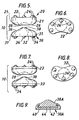
- the shape of the artificial spinal disc 10 is generally oval as shown in Figs. 6 and 8.
- the recessed receiving mount 28 of the artificial spinal disc 10 is located at or near the center of the supporting block 20.
- the projection 38 of the artificial spinal disc 10 is located similarly at or near the center of the intervertebral bearing block 30.
- the supporting block 20 and the bearing block 30 are provided respectively with one or more protuberances 24, 34 which can be in the form of pegs, posts or screws, and are located at any preselected position on the outer surfaces 22, 32 respectively of the supporting block 20 and bearing block 30. Additionally, flat beaded surfaces on the outer surfaces 22, 32 or other securing means can be used to hold the artificial spinal disc 10 in place in the adjacent vertebrae.
- a bearing block 30A has a projection or ball segment 38A and a base plate 40, similar in concept to a miniscal bearing knee, which allows for a certain amount of translation in combination with the rotation and bending allowed by the ball-socket design features.
- the supporting block 20, instead of the bearing block 30A could have a recessed receiving mount and a base plate (not shown) identical to the bearing block 30A. This feature can improve the stability and resistance to dislocation of the implant 10A.
- a ceramic surface on a ceramic surface (in addition to metal-metal) can be employed for the two opposing, flat translating surfaces 42 44, as the contact stresses will be greatly reduced with such conformal surfaces.
- the base plates 40, 42 which can be formed of titanium or titanium alloy, can be attached to the supporting block 20A and the bearing block 30A mechanically or via shrink-fit or welding methods.
- the intervertebral supporting block 20 and the intervertebral bearing block 30 can be made of metal material such stainless steel 316 LVM, or titanium-6-4, or cobalt/chrome alloy, which are all suitable for orthopedic surgery.
- metal material such as stainless steel 316 LVM, or titanium-6-4, or cobalt/chrome alloy, which are all suitable for orthopedic surgery.
- a ceramic material such as hydroxyapatite, and the biologically compatible organic polymer such as HDPE may be used to make the artificial spinal disc 10 of the present invention.
- the recessed receiving mount 28 and the projection 38 of the artificial spinal disc 10 are formed of a hard Cr-containing metal which is attached to titanium, titanium alloy, cobalt/chrome alloy, zirconium or zirconium alloy base components 23, 33 respectively as shown in Fig. 7.
- the preferred material for the base components 23, 33 is titanium or titanium alloy to minimize shadow effects from MRI imaging.
- the preferred embodiment utilizes a macro-textured or porous-coated outer side 22, 32 with the anchoring pegs or screws 24, 34 being porous-coated or macro-textured also.
- the preferred material for the recessed receiving mount 28 and projection 38 is a Cr-containing iron or cobalt alloy with chromium in excess of about 15 weight % chromium, and the addition of about 2-6 weight % molybdenum to improve corrosion resistance in chloride-containing environments.
- Acceptable examples include A.I.S.I. 316 L stainless steel or ASTM F-75 cast Co-Cr-Mo or ASTM F-799 wrought Co-Cr-Mo alloy, all currently used in medical implant applications.
- a surface-hardened Cr-containing metal such as that described by Davidson in U.S. patent 5,415,704.
- Such alloy compositions produce minimal wear, are tolerant of three-body abrasion, and produce a relatively lubricious Cr/oxyhyroxide surface layer which enhances motion and wear resistance.
- the present invention thus provides an unrestricted ball and socket-type artificial spinal disc containing low wear bearing surfaces of chromium containing metals, precision machined to minimize contact stress and anchored to the adjacent vertebrae with press fit or cemented methods known in the art of joint replacement.
- the artificial spinal disc 10 and 10A can be implanted to replace a degenerated or diseased intervertebral disc by conventional orthopedic surgery which is well known in the art.
- the artificial spinal disc 10 and 10A is configured so as to allow the implant 10, 10A, to be implanted as a one piece unit rather than inserting one component at a time, which eliminates the need for over distraction of the adjacent vertebrae.
- a bone resection technique that allows for the implantation of the implant as a single unit, openings or channels are formed in the bone of the adjacent vertebrae in a shape that conforms to the projections 24, 34.
- the implant 10, 10A is slid in place between the resection lines, as one unit, which prevents the need for over distraction, which can place unnecessary stresses on the surrounding structures.
Abstract
Description
- The present invention relates to an artificial intervertebral disc, and more particularly but not exclusively to a low wear, hard chromium-coating metal ball and socket bearing system allowing unrestricted motion for use in the replacement of spinal disc segments. See US-A-5258031 for a disc device in accordance with the pre-characterising part of claim 1, below.
There have been numerous types of implants designed to replace damaged spinal disc segments of the human body in which an artificial intervertebral disc is used to replace a deformed, injured or diseased natural intervertebral disc. Such an artificial intervertebral disc is generally composed of a rigid solid body that causes the vertebrae adjacent to the implanted artificial disc to be limited in its ability to move relative to each other. Some of these solid body artificial intervertebral discs are disclosed in U.S. patents 4,349,921; 4,553,273; and 4,714,469. Other artificial discs are provided with a spring which permits the vertebrae adjacent to the implanted artificial disc to have a limited amount of motion in limited directions. These are described in U.S. patents 4,309,777 and 4,759,769. - It has also been proposed that soft compliant polymers be used to assure separation of damaged disc segments or as bearing surfaces. However, polymers can degrade with time in the human body and also be susceptible to abrasion damage by the bone surface. Further, polymeric disc replacements are susceptible to creep and gradual changes in dimensional characteristics. But polymers are favored due to their low stiffness and relative improvement in shock absorbing characteristics. Artificial intervertebral discs having a main body formed of an elastic polymer are disclosed in U.S. patents 3,867,729; 4,863,477 and 4,911,71. U.S. patent 5,071,437 discloses an artificial intervertebral disc composed of an elastomeric core sandwiched between two metal plates. This disc is further provided with a plurality of spikes for stabilizing the vertebrae adjacent to the implanted disc. However, the biocompatability of this disc is uncertain because it contains a polymer and a curing agent used to hold the metal plates and the elastomeric core together.
- Ball and socket type artificial spinal discs have been proposed but, without polymer components they have less shock absorbing capabilities. Further, there is no clinical proof that shock absorption is necessary, as adjacent discs can compensate for a reduced level of shock absorption in one or two discs along the entire spinal column.
- Non-polymeric disc components include ceramic and metal materials and designs have included hinged, sliding and ball and socket-type solutions. The hinged design frequently is constraining, and the patient cannot effectively move in some directions. Sliding disc surfaces generally do not have the ability to accommodate bending or twisting motion, but do help assist with natural translation motion tendencies within the disc space. However, due to the small space between adjacent vertebrae, the contact stress with only this type of single (translation) motion capability between the sliding surfaces can lead to excessive wear and eventual disfunction of the artificial intervertebral disc.
- The most logical solution for spinal disc replacement is the ball and socket-type design. Ceramics have been proposed, but ceramic surfaces are extremely hard and prone to excessive contact stress and wear if three-body particles or debris become lodged between the two surfaces. Without film lubrication to separate the two ceramic surfaces, high hertzian contact stresses can fracture the hard surface, leading to continued and accelerated surface wear damage. Debris, such as bone chips, can readily create this adverse three-body wear process. Further, because of the relatively high stiffness of ceramics, implant design and machining must be such that surface contact is optimized. Such precision machining is extremely difficult to accomplish with ceramic surfaces.
- Hard, metal surfaces which are passivated by relatively soft, lubricious oxides and oxyhydroxides (i.e., Cr-containing metals) are much more tolerant to the occasional severe, high contact stress wear conditions found in the vertebral column. However, this type of ball and socket system is only effective under normal, non-extreme motion. During extreme motion and bending of the spinal column, the ball can "rock out" of the socket and impinge the device edges, creating high stresses and wear. Metals would be more tolerant under these extreme conditions than hard ceramic, but metal components can also experience some wear conditions. Therefore, allowance in the implant design to minimize contact stress in these extreme motion conditions is also desirable.
- Other designs using either ceramic or metal materials also restrict motion relative to the adjacent vertebrae. Some skilled in the art feel that, because the natural healthy disc experiences a limit of about 11° motion in the anterior-posterior plane (bending forward/backward) and a limit of about 3-5° motion in the medial-lateral plane (bending side-to-side), the artificial disc replacement must also have this limitation, which causes other adjacent discs to take up the strain. Further, some skilled in the art argue that there must be a restriction to rotation (1-2°) within the artificial disc for the same reasons. For example, U.S. patent 4,759,769 discloses a hinged/spring design with a limitation of 20° in flexion/extension and allowance of a small amount of side-to-side rocking. Rotation is restricted with this device. U.S. patent 5,071,437 describes an implant device that limits flexion/extension and lateral bending to physiologic angles and allows for only 2-3° of rotation. This device also allows for 1-2 mm of transition. U.S. patent 4,759,766 describes a device composed of two cobalt/chrome end plates with a domed polyethylene central core which allows 10° flexion/extension, a small amount of lateral bending, and is rotationally restricted. The addition of these anatomical restrictions to disc replacement designs limit the type and effectiveness of the design and the materials that may be employed. For example, if the disc prosthesis exceeds its 11° bending restriction, than as mentioned above, the non-bearing surfaces will contact each other and inappropriately displace the prosthesis or create an adverse wear situation.
- It is felt that restrictions in disc prosthesis design may not only create a performance liability, but are also not needed. The surrounding ligaments, muscles, and other tissues provide a built-in restriction to anterior/posterior, medial-lateral, and twisting motions of the artificial intervertebral disc, at least to a point in which adjacent discs are not significantly affected.
- For the reasons mentioned above, the present invention, in preferred embodiments provides an unrestricted ball and socket-type artificial spinal disc containing low wear bearing surfaces of chromium containing metals, precision machined to minimize contact stress and anchored to the adjacent vertebrae with press fit or cemented methods known in the art of joint replacement. To accommodate extreme motion, the peripheral areas of the ball and socket type intervertebral disc are designed to minimize stress and wear. This design can also incorporate the ability to translate, similar to that for a miniscal bearing knee. Additionally, the bearing portions of the disc of the artificial intervertebral disc can be attached to a different material for anchoring the disc portions to the adjacent bone.
- The present invention is defined in claim 1 below, and provides an artificial spinal disc for surgical placement between adjacent vertebrae. The apparatus of the present invention provides a low wear artificial spinal disc that includes a first component for attaching to a first vertebrae having a concave recess, with the concave contoured surface having a circumference of 360°. A second component for attaching to a second vertebrae has a projection that fits the concave recess of the first component, with the convex contoured surface having a circumference of 360°. The corresponding contoured surfaces allow an unrestricted rotational and a relatively unrestricted flexion/. extension bending motion between the first and second components relative to a patient's normal spinal axis when in a standing position with the spine in a straightened position.
- In another embodiment of the present invention there is provided an artificial spinal disc for surgical placement between first and second adjacent vertebrae of a patient's spine, comprising:
- (a) a first component for attaching to the first vertebrae, said first component including a base portion and a bearing portion, said bearing portion including a concave recess, the concave contoured surface having a circumference of 360°;
- (b) a second component for attaching to the second vertebrae, said second component including a base portion and a bearing portion, said bearing portion including a projection that fits the concave recess of the first component, the convex contoured surface having a circumference of 360°;
- (c) the corresponding bearing portions being configured so as to allow an unrestricted rotational and a flexion/extension bending motion between the first and second components relative to a patient's normal spinal axis when in a standing position with the spine in a straightened position.
-
- In a further embodiment of the present invention there is provided an artificial spinal disc for surgical placement between first and second adjacent vertebrae of a patient's spine, comprising:
- (a) a first component for attaching to the first vertebrae, said first component including a concave recess, the concave contoured surface having a circumference of 360°;
- (b) a second component for attaching to the second vertebrae, said second component including a projection that fits the concave recess of the first component, the convex contoured surface having a circumference of 360°;
- (c) the corresponding contoured surfaces being configured so as to allow an unrestricted rotational and a flexion /extension bending motion between the first and second components relative to a patient's normal spinal axis when in a standing position with the spine in a straightened position;
- (d) wherein the first and second components are configured so as to allow the artificial spinal disc to be implanted as one unit in which openings in bone of the adjacent vertebrae are created in order to allow the artificial spinal disc to be slid into place so as to prevent over distraction.
-
- The invention will become more apparent when the detailed description of exemplary embodiments is considered in conjunction with the appended drawings, in which:
- Figure 1 is a exploded view of a spinal disc, not in accordance with the present invention;
- Figure 2 is a side sectional view of the disc shown in Figure 1;
- Figure 3 is the reverse of the exploded view of the disc shown in Figure 1;
- Figure 4 is a side section view of the disc shown in Figure 3;
- Figure 5 is a side elevational view of an alternate shape of disc, in accordance with the present invention;
- Figure 6 is a end plan view of a first component of the disc shown in Figure 5;
- Figure 7 is a side elevational exploded view of an alternate configuration of disc in accordance with the present invention;
- Figure 8 is an end plan view of a second component of the disc shown in Figure 5;
- FIGURE 9 is a side sectional view of an alternate embodiment of the present invention;
- FIGURE 10 is a plan view of the inner side of the first component as shown in Fig. 5;
- FIGURE 11 is a plan view of the inner side of the second component as shown in Fig. 5;
- Figure 12 is a side, partial phantom view of the components of an embodiment of the present invention in a joined relation; and
- Figure 13 is a top plan view of the components of an embodiment of the present invention in a joined relation showing rotational motion.
-
- As shown in Figs. 1-4, a low wear artificial spinal or
intervertebral disc 10 includes a first component orintervertebral support block 20 for attaching to the end plate of a first vertebrae and a second component orintervertebral bearing block 30 for attaching to the end plate of a second adjoining vertebrae. Theintervertebral support block 20 has anouter side 22 provided with one ormore protuberances 24 such as pegs, posts or screws and aninner side 26 which has a concave recess or recessed receivingmount 28 forming a socket-like segment located near the center of the support block 20 (Fig. 10). The concave contoured surface of the receivingmount 28 has a circumference of 360°. - The
intervertebral bearing block 30 has anouter side 32 with one ormore protuberances 34, such as pegs, posts or screws, and aninner side 36 which has aprojection 38 with a convex surface forming a ball-like segment (Fig. 11), the convex surface having a circumference of 360°. Theprojection 38 corresponds in location to the recessed receivingmount 28 of the supportingblock 20 and is shaped so as to fit rotatably into the recessed receivingmount 28 of the supportingblock 20, as shown in Figs. 10-12. Theprojection 38 of thebearing block 30 and the recessed receivingmount 28 of the supportingblock 20 are shaped so as to form a ball and socket-type device which allows for unrestricted rotational (Fig. 13) and relatively unrestriced flexion/extension bending motion (Fig. 12) between the supportingblock 20 and bearingblock 30 relative to a patient's normal spinal axis when in a standing position with the spine in a straightened position. Theinner side 26 of the supportingblock 20 and theinner side 36 of thebearing block 30 are provided respectively with a surface curving or sloping slightly outwards to aperiphery block 20 and bearingblock 30, as shown in Figs. 2-4, 5 and 7. Thus, theinner side 26 of the supportingblock 20 has inclined surfaces between theperiphery 21 of the supportingblock 20 and the recessed receivingmount 28. Likewise, theinner side 36 of thebearing block 30 has inclined surfaces between theperiphery 31 of thebearing block 30 and theprojection 38, as shown in Figs. 5 and 12. - As a result, the configuration of the supporting
block 20 and bearingblock 30 allows for a considerable angle of flexion/extension generally of about between 20-30° within which each can turn, as illustrated in Fig. 12, thereby enabling a patient with the implanted artificialintervertebral disc 10 to have generally normal motion and rotation of the spinal column. - The
outer sides block 20 andintervertebral bearing block 30 can be substantially flat, slightly concave, or curved in various forms. However, flat or slightly concave outer surfaces are preferable and can be covered with a coating of material corresponding to the material that forms the supportingblock 20 and thebearing block 30. Such coated outer surfaces are similar in formation to those disclosed in U.S. patent 5,071,437. - With the exception of the recessed receiving
mount 28, theinner side 26 of the supportingblock 20 is substantially flat or slightly convex. A slightly convexinner side 26 is preferable because such a surface enables the supportingblock 20 and thebearing block 30 to rotate 360° relative to each other. Similarly, with the exception of theprojection 38, theinner side 36 of thebearing block 30 is substantially flat or slightly convex. A slightly convexinner side 36 is preferable for the same reason as discussed above. - The artificial
spinal disc 10 of the present invention is shaped so as to provide minimal restriction to bending and no restriction to rotational motion between the adjacent vertebrae, all of which are limitations found in other previous disc designs. In a preferred embodiment of the present invention, as shown in Figs. 5 and 7, the edges of the recessed receivingmount 28 or socket segment recede quickly in order to maximize bending clearance. The edges of the recessed receivingmount 28 blend into theinner side 26 gradually and at a convex radius similar to that of theprojection 38 in order to minimize contact stress and wear in extreme motion conditions. This feature also improves stability of the implant under extreme motion conditions. Theprojection 38 or ball segment likewise recedes quickly from the bearing region and blends gradually into theinner side 36. Theprojection 38 is preferably located approximately in the center of theimplant 10 but may be designed such that the surgeon has an option of this location depending on patient needs. - The
projection 38 of thebearing block 30 is of a generally hemispherical construction and conforms in shape to the concave surface of the receivingmount 28 such that theprojection 38 is capable of rotating freely 360° in the recessed receivingmount 28. The shape of the recessed receivingmount 28 is substantially similar in curvature to theprojection 38. The convex surface ofprojection 38 is of a depth or thickness that corresponds to or is greater than a depth of the concavity of the recessed receivingmount 28. In order to allow the supportingblock 20 and thebearing block 30 to rotate freely in relation to each other, the depth or thickness of the convex surface of theprojection 38 should be slightly greater than the depth of the concavity of the recessed receivingmount 28 assuming that the recessed receivingmount 28 andprojection 38 are provided respectively with a flat surface. - The intervertebral supporting
block 20 and theintervertebral bearing block 30 have a total height or thickness that is dependent on the height or thickness of the deformed intervertebral disc that it is replacing. In addition, the supportingblock 20 and thebearing block 30 have a shape that is dependent on the shape of the vertebrae adjacent to the intervertebral disc being replaced. In a preferred embodiment, the shape of the artificialspinal disc 10 is generally oval as shown in Figs. 6 and 8. - The recessed receiving
mount 28 of the artificialspinal disc 10 is located at or near the center of the supportingblock 20. Likewise, theprojection 38 of the artificialspinal disc 10 is located similarly at or near the center of theintervertebral bearing block 30. - The supporting
block 20 and thebearing block 30 are provided respectively with one ormore protuberances outer surfaces block 20 and bearingblock 30. Additionally, flat beaded surfaces on theouter surfaces spinal disc 10 in place in the adjacent vertebrae. - Translation of the primary wear surfaces is not necessary. However, in an alternate embodiment of spinal implant 10A, as shown in Fig. 9, a bearing block 30A has a projection or
ball segment 38A and a base plate 40, similar in concept to a miniscal bearing knee, which allows for a certain amount of translation in combination with the rotation and bending allowed by the ball-socket design features. Alternatively, the supportingblock 20, instead of the bearing block 30A, could have a recessed receiving mount and a base plate (not shown) identical to the bearing block 30A. This feature can improve the stability and resistance to dislocation of the implant 10A. In this alternate embodiment, a ceramic surface on a ceramic surface (in addition to metal-metal) can be employed for the two opposing, flat translating surfaces 42 44, as the contact stresses will be greatly reduced with such conformal surfaces. To avoid or minimize potential dislocation of the ball and socket, the base plates 40, 42, which can be formed of titanium or titanium alloy, can be attached to the supporting block 20A and the bearing block 30A mechanically or via shrink-fit or welding methods. - The intervertebral supporting
block 20 and theintervertebral bearing block 30 can be made of metal material such stainless steel 316 LVM, or titanium-6-4, or cobalt/chrome alloy, which are all suitable for orthopedic surgery. In addition, a ceramic material such as hydroxyapatite, and the biologically compatible organic polymer such as HDPE may be used to make the artificialspinal disc 10 of the present invention. - In a preferred embodiment, the recessed receiving
mount 28 and theprojection 38 of the artificialspinal disc 10 are formed of a hard Cr-containing metal which is attached to titanium, titanium alloy, cobalt/chrome alloy, zirconium or zirconiumalloy base components base components outer side - The preferred material for the recessed receiving
mount 28 andprojection 38 is a Cr-containing iron or cobalt alloy with chromium in excess of about 15 weight % chromium, and the addition of about 2-6 weight % molybdenum to improve corrosion resistance in chloride-containing environments. Acceptable examples include A.I.S.I. 316 L stainless steel or ASTM F-75 cast Co-Cr-Mo or ASTM F-799 wrought Co-Cr-Mo alloy, all currently used in medical implant applications. However, due to the relatively high contact pressures incurred in ball-socket connections within the confined space between adjoining vertebrae, it is preferable to use a surface-hardened Cr-containing metal such as that described by Davidson in U.S. patent 5,415,704. Such alloy compositions produce minimal wear, are tolerant of three-body abrasion, and produce a relatively lubricious Cr/oxyhyroxide surface layer which enhances motion and wear resistance. - The present invention thus provides an unrestricted ball and socket-type artificial spinal disc containing low wear bearing surfaces of chromium containing metals, precision machined to minimize contact stress and anchored to the adjacent vertebrae with press fit or cemented methods known in the art of joint replacement. The artificial
spinal disc 10 and 10A can be implanted to replace a degenerated or diseased intervertebral disc by conventional orthopedic surgery which is well known in the art. - The artificial
spinal disc 10 and 10A is configured so as to allow theimplant 10, 10A, to be implanted as a one piece unit rather than inserting one component at a time, which eliminates the need for over distraction of the adjacent vertebrae. In a bone resection technique that allows for the implantation of the implant as a single unit, openings or channels are formed in the bone of the adjacent vertebrae in a shape that conforms to theprojections implant 10, 10A is slid in place between the resection lines, as one unit, which prevents the need for over distraction, which can place unnecessary stresses on the surrounding structures.
Claims (11)
- An artificial spinal disc (10, 10A) for surgical placement between first and second adjacent vertebrae of a patient's spine, comprising:characterized in that:(a) a first component (20) for attaching to the first vertebrae, said first component (20) including a periphery (21), an inner side (26) and in the centre of the inner side a concave recess (28), the concave contoured surface of the recess having a circumference of 360°;(b) a second component (30) for attaching to the second vertebrae, said second component (30) including a periphery (31), an inner side (36) and in the centre of the inner side a projection (38) that fits the concave recess (28) of the first component (20), the projection (38) having a convex contoured surface having a circumference of 360°;(c) the corresponding fitting concave and convex contoured surfaces being configured so as to allow an unrestricted rotational and a flexion / extension bending motion between the first and second components (20, 30) relative to a patient's normal spinal axis when in a standing position with the spine in the straightened position;the inner side (26) of the supporting block (20) and the inner side (36) of the bearing block (30) are curved surfaces which blend gradually into the respective convex or concave contoured surface (38, 28) and the respective periphery (21, 31).
- The artificial spinal disc of claim 1, wherein at least one of the surfaces is formed from a chromium-containing metal having a chromium content in excess of 15 weight percent.
- The artificial spinal disc of claim 1, wherein at least one of the contoured surfaces is formed from a cobalt-chromium-molybdenum alloy.
- The artificial spinal disc of claim 1, wherein at least one of the contoured surfaces is coated with a cobalt-chromium-molybdenum tantalum alloy with tantalum replacing the cobalt and being less than about 5 weight percent.
- The artificial spinal disc of an one of the preceding claims, wherein the first (20) and second (30) component include anchoring means (24, 34) for attachment to the respective first and second vertebrae.
- The artificial spinal disc of claim 5, wherein the anchoring means (24, 34) includes a porous-coated or macro-textured surface to facilitate bone ingrowth.
- An artificial spinal disc of any one of the preceding claims, wherein the components are generally oval in shape with the contoured surfaces being positioned approximately in the centre of the component.
- An artificial spinal disc of any one of the preceding claims, wherein the first and second components are configured so as to allow the artificial spinal disc to be implanted as one unit in a process in which over-distraction is eliminated.
- The artificial spinal disc of any one of the preceding claims, wherein at least one of the components comprises a base portion (40) and a bearing portion, and wherein at least one of the base portions of a component includes means for translation between the bearing portions.
- The artificial spinal disc of any of the preceding claims, wherein at least one of the components comprises a base portion (40) and a bearing portion, and wherein at least one of the base portions is formed from a material different from the material of the bearing portion.
- An artificial spinal disc as claimed in any one of the preceding claims wherein the first (20) and second components (30) are configured so as to allow the artificial spinal disc to be implanted as one unit in a process in which openings in bone of the adjacent vertebrae are created in order to allow the artificial spinal disc (10, 10A) to be slid into place so as to prevent over-distraction.
Applications Claiming Priority (2)
| Application Number | Priority Date | Filing Date | Title |
|---|---|---|---|
| US08/480,762 US5676701A (en) | 1993-01-14 | 1995-06-07 | Low wear artificial spinal disc |
| US480762 | 2000-01-10 |
Publications (2)
| Publication Number | Publication Date |
|---|---|
| EP0747025A1 EP0747025A1 (en) | 1996-12-11 |
| EP0747025B1 true EP0747025B1 (en) | 2002-09-11 |
Family
ID=23909262
Family Applications (1)
| Application Number | Title | Priority Date | Filing Date |
|---|---|---|---|
| EP96304205A Expired - Lifetime EP0747025B1 (en) | 1995-06-07 | 1996-06-06 | Low wear artificial spinal disc |
Country Status (4)
| Country | Link |
|---|---|
| US (1) | US5676701A (en) |
| EP (1) | EP0747025B1 (en) |
| AT (1) | ATE223681T1 (en) |
| DE (1) | DE69623535T2 (en) |
Cited By (9)
| Publication number | Priority date | Publication date | Assignee | Title |
|---|---|---|---|---|
| WO2005094734A1 (en) | 2004-03-30 | 2005-10-13 | Hjs Gelenk System Gmbh | Artificial intervertebral disk |
| US7179294B2 (en) | 2002-04-25 | 2007-02-20 | Warsaw Orthopedic, Inc. | Articular disc prosthesis and method for implanting the same |
| US7655045B2 (en) | 2003-05-06 | 2010-02-02 | Aesculap Implant Systems, Llc | Artificial intervertebral disc |
| US7763075B2 (en) | 2003-04-04 | 2010-07-27 | Theken Spine, Llc | Artificial disc prosthesis |
| US7780676B2 (en) | 2006-07-11 | 2010-08-24 | Ebi, Llc | Intervertebral implantation apparatus |
| US7832409B2 (en) | 2003-05-06 | 2010-11-16 | Aesculap Implant Systems, Llc | Method of inserting an artificial intervertebral disc |
| US7850735B2 (en) | 2003-02-12 | 2010-12-14 | Warsaw Orthopedic, Inc. | Articular disc prosthesis and method for treating spondylolisthesis |
| US7959678B2 (en) | 2004-05-18 | 2011-06-14 | Zimmer Gmbh | Intervertebral disk implant |
| US8721722B2 (en) | 2004-10-18 | 2014-05-13 | Ebi, Llc | Intervertebral implant and associated method |
Families Citing this family (544)
| Publication number | Priority date | Publication date | Assignee | Title |
|---|---|---|---|---|
| US7494507B2 (en) | 2000-01-30 | 2009-02-24 | Diamicron, Inc. | Articulating diamond-surfaced spinal implants |
| US5674296A (en) | 1994-11-14 | 1997-10-07 | Spinal Dynamics Corporation | Human spinal disc prosthesis |
| EP0934026B1 (en) | 1996-10-24 | 2009-07-15 | Zimmer Spine Austin, Inc | Apparatus for spinal fixation |
| US6416515B1 (en) | 1996-10-24 | 2002-07-09 | Spinal Concepts, Inc. | Spinal fixation system |
| US6045579A (en) * | 1997-05-01 | 2000-04-04 | Spinal Concepts, Inc. | Adjustable height fusion device |
| GB9713330D0 (en) * | 1997-06-25 | 1997-08-27 | Bridport Gundry Plc | Surgical implant |
| US5928243A (en) | 1997-07-16 | 1999-07-27 | Spinal Concepts, Inc. | Pedicle probe and depth gage |
| KR20010022695A (en) | 1997-08-04 | 2001-03-26 | 고든 마야 로버츠 앤드 토마스 넘버 1 엘엘씨 | Multiple axis intervertebral prosthesis |
| US6030389A (en) | 1997-08-04 | 2000-02-29 | Spinal Concepts, Inc. | System and method for stabilizing the human spine with a bone plate |
| US6454769B2 (en) | 1997-08-04 | 2002-09-24 | Spinal Concepts, Inc. | System and method for stabilizing the human spine with a bone plate |
| US6146421A (en) * | 1997-08-04 | 2000-11-14 | Gordon, Maya, Roberts And Thomas, Number 1, Llc | Multiple axis intervertebral prosthesis |
| US6053921A (en) | 1997-08-26 | 2000-04-25 | Spinal Concepts, Inc. | Surgical cable system and method |
| US5964769A (en) | 1997-08-26 | 1999-10-12 | Spinal Concepts, Inc. | Surgical cable system and method |
| AT405237B (en) * | 1997-08-28 | 1999-06-25 | Ronald J Dr Sabitzer | SPINE PROSTHESIS |
| US5899941A (en) * | 1997-12-09 | 1999-05-04 | Chubu Bearing Kabushiki Kaisha | Artificial intervertebral disk |
| ES2163216T3 (en) * | 1998-03-13 | 2002-01-16 | Link Waldemar Gmbh Co | ENDOPROTESIS GAME FOR INTERVERTEBRAL DISCS. |
| JP2002521090A (en) | 1998-07-22 | 2002-07-16 | スパイナル ダイナミックス コーポレイション | Single or Multiple Row Threaded Cylindrical Disc Prosthesis Using Multiple Disc Members |
| US6063121A (en) * | 1998-07-29 | 2000-05-16 | Xavier; Ravi | Vertebral body prosthesis |
| US6749635B1 (en) | 1998-09-04 | 2004-06-15 | Sdgi Holdings, Inc. | Peanut spectacle multi discoid thoraco-lumbar disc prosthesis |
| US6113637A (en) | 1998-10-22 | 2000-09-05 | Sofamor Danek Holdings, Inc. | Artificial intervertebral joint permitting translational and rotational motion |
| US6039763A (en) * | 1998-10-27 | 2000-03-21 | Disc Replacement Technologies, Inc. | Articulating spinal disc prosthesis |
| FR2787017B1 (en) | 1998-12-11 | 2001-04-27 | Dimso Sa | INTERVERTEBRAL DISC PROSTHESIS WITH IMPROVED MECHANICAL BEHAVIOR |
| FR2787015B1 (en) * | 1998-12-11 | 2001-04-27 | Dimso Sa | INTERVERTEBRAL DISC PROSTHESIS WITH COMPRESSIBLE BODY |
| US6113638A (en) | 1999-02-26 | 2000-09-05 | Williams; Lytton A. | Method and apparatus for intervertebral implant anchorage |
| AU3187000A (en) * | 1999-03-07 | 2000-09-28 | Discure Ltd. | Method and apparatus for computerized surgery |
| US6368350B1 (en) * | 1999-03-11 | 2002-04-09 | Sulzer Spine-Tech Inc. | Intervertebral disc prosthesis and method |
| US6602291B1 (en) | 1999-04-05 | 2003-08-05 | Raymedica, Inc. | Prosthetic spinal disc nucleus having a shape change characteristic |
| US6110210A (en) * | 1999-04-08 | 2000-08-29 | Raymedica, Inc. | Prosthetic spinal disc nucleus having selectively coupled bodies |
| US6557226B1 (en) | 1999-04-23 | 2003-05-06 | Michael E. Landry | Apparatus for manufacturing a bone dowel |
| US7273497B2 (en) | 1999-05-28 | 2007-09-25 | Anova Corp. | Methods for treating a defect in the annulus fibrosis |
| US20060247665A1 (en) | 1999-05-28 | 2006-11-02 | Ferree Bret A | Methods and apparatus for treating disc herniation and preventing the extrusion of interbody bone graft |
| US20070038231A1 (en) | 1999-05-28 | 2007-02-15 | Ferree Bret A | Methods and apparatus for treating disc herniation and preventing the extrusion of interbody bone graft |
| DE59914691D1 (en) | 1999-07-02 | 2008-04-24 | Spine Solutions Inc | INTERVERTEBRAL IMPLANT |
| US7717961B2 (en) | 1999-08-18 | 2010-05-18 | Intrinsic Therapeutics, Inc. | Apparatus delivery in an intervertebral disc |
| US7220281B2 (en) | 1999-08-18 | 2007-05-22 | Intrinsic Therapeutics, Inc. | Implant for reinforcing and annulus fibrosis |
| US7972337B2 (en) | 2005-12-28 | 2011-07-05 | Intrinsic Therapeutics, Inc. | Devices and methods for bone anchoring |
| US7553329B2 (en) | 1999-08-18 | 2009-06-30 | Intrinsic Therapeutics, Inc. | Stabilized intervertebral disc barrier |
| US8323341B2 (en) | 2007-09-07 | 2012-12-04 | Intrinsic Therapeutics, Inc. | Impaction grafting for vertebral fusion |
| WO2004100841A1 (en) | 1999-08-18 | 2004-11-25 | Intrinsic Therapeutics, Inc. | Devices and method for augmenting a vertebral disc nucleus |
| CA2425951C (en) | 1999-08-18 | 2008-09-16 | Intrinsic Therapeutics, Inc. | Devices and method for nucleus pulposus augmentation and retention |
| WO2009033100A1 (en) | 2007-09-07 | 2009-03-12 | Intrinsic Therapeutics, Inc. | Bone anchoring systems |
| US7998213B2 (en) | 1999-08-18 | 2011-08-16 | Intrinsic Therapeutics, Inc. | Intervertebral disc herniation repair |
| US6425919B1 (en) | 1999-08-18 | 2002-07-30 | Intrinsic Orthopedics, Inc. | Devices and methods of vertebral disc augmentation |
| ATE354324T1 (en) | 1999-09-14 | 2007-03-15 | Spine Solutions Inc | INSERTION INSTRUMENT FOR AN INTERVERBEL IMPLANT |
| US6264695B1 (en) * | 1999-09-30 | 2001-07-24 | Replication Medical, Inc. | Spinal nucleus implant |
| US7052516B2 (en) | 1999-10-20 | 2006-05-30 | Anulex Technologies, Inc. | Spinal disc annulus reconstruction method and deformable spinal disc annulus stent |
| US7615076B2 (en) | 1999-10-20 | 2009-11-10 | Anulex Technologies, Inc. | Method and apparatus for the treatment of the intervertebral disc annulus |
| US7935147B2 (en) | 1999-10-20 | 2011-05-03 | Anulex Technologies, Inc. | Method and apparatus for enhanced delivery of treatment device to the intervertebral disc annulus |
| US8128698B2 (en) | 1999-10-20 | 2012-03-06 | Anulex Technologies, Inc. | Method and apparatus for the treatment of the intervertebral disc annulus |
| US7951201B2 (en) | 1999-10-20 | 2011-05-31 | Anulex Technologies, Inc. | Method and apparatus for the treatment of the intervertebral disc annulus |
| US7004970B2 (en) | 1999-10-20 | 2006-02-28 | Anulex Technologies, Inc. | Methods and devices for spinal disc annulus reconstruction and repair |
| US6592625B2 (en) | 1999-10-20 | 2003-07-15 | Anulex Technologies, Inc. | Spinal disc annulus reconstruction method and spinal disc annulus stent |
| US8632590B2 (en) | 1999-10-20 | 2014-01-21 | Anulex Technologies, Inc. | Apparatus and methods for the treatment of the intervertebral disc |
| US7691145B2 (en) | 1999-10-22 | 2010-04-06 | Facet Solutions, Inc. | Prostheses, systems and methods for replacement of natural facet joints with artificial facet joint surfaces |
| EP2204144B1 (en) | 1999-10-22 | 2013-04-03 | Gmedelaware 2 LLC | Facet arthroplasty devices and methods |
| US8187303B2 (en) | 2004-04-22 | 2012-05-29 | Gmedelaware 2 Llc | Anti-rotation fixation element for spinal prostheses |
| US6974478B2 (en) * | 1999-10-22 | 2005-12-13 | Archus Orthopedics, Inc. | Prostheses, systems and methods for replacement of natural facet joints with artificial facet joint surfaces |
| US7674293B2 (en) | 2004-04-22 | 2010-03-09 | Facet Solutions, Inc. | Crossbar spinal prosthesis having a modular design and related implantation methods |
| US6331179B1 (en) | 2000-01-06 | 2001-12-18 | Spinal Concepts, Inc. | System and method for stabilizing the human spine with a bone plate |
| US6447512B1 (en) | 2000-01-06 | 2002-09-10 | Spinal Concepts, Inc. | Instrument and method for implanting an interbody fusion device |
| FR2805733B1 (en) | 2000-03-03 | 2002-06-07 | Scient X | DISC PROSTHESIS FOR CERVICAL VERTEBRUS |
| US6805695B2 (en) | 2000-04-04 | 2004-10-19 | Spinalabs, Llc | Devices and methods for annular repair of intervertebral discs |
| US6949105B2 (en) | 2000-08-08 | 2005-09-27 | Sdgi Holdings, Inc. | Method and apparatus for stereotactic implantation |
| AU8116601A (en) | 2000-08-08 | 2002-02-18 | Spinal Dynamics Corp | Implantable joint prosthesis |
| US6579319B2 (en) | 2000-11-29 | 2003-06-17 | Medicinelodge, Inc. | Facet joint replacement |
| US6419703B1 (en) | 2001-03-01 | 2002-07-16 | T. Wade Fallin | Prosthesis for the replacement of a posterior element of a vertebra |
| US6565605B2 (en) | 2000-12-13 | 2003-05-20 | Medicinelodge, Inc. | Multiple facet joint replacement |
| US6562045B2 (en) | 2001-02-13 | 2003-05-13 | Sdgi Holdings, Inc. | Machining apparatus |
| US6863688B2 (en) | 2001-02-15 | 2005-03-08 | Spinecore, Inc. | Intervertebral spacer device utilizing a spirally slotted belleville washer having radially spaced concentric grooves |
| US8940047B2 (en) | 2001-02-15 | 2015-01-27 | Spinecore, Inc. | Intervertebral spacer device having recessed notch pairs for manipulation using a surgical tool |
| US6669730B2 (en) | 2001-02-15 | 2003-12-30 | Spinecore, Inc. | Intervertebral spacer device utilizing a spirally slotted belleville washer having radially extending grooves |
| US20050125064A1 (en) * | 2001-02-15 | 2005-06-09 | Spinecore, Inc. | Intervertebral spacer device |
| US6740117B2 (en) * | 2001-02-15 | 2004-05-25 | Spinecore, Inc. | Intervertebral spacer device having a radially thinning slotted belleville spring |
| US7115132B2 (en) | 2001-07-16 | 2006-10-03 | Spinecore, Inc. | Static trials and related instruments and methods for use in implanting an artificial intervertebral disc |
| US7223291B2 (en) * | 2001-07-16 | 2007-05-29 | Spinecore, Inc. | Intervertebral spacer device having engagement hole pairs for manipulation using a surgical tool |
| US7604664B2 (en) | 2001-07-16 | 2009-10-20 | Spinecore, Inc. | Spinal baseplates with ball joint coupling and a retaining member |
| US7169182B2 (en) | 2001-07-16 | 2007-01-30 | Spinecore, Inc. | Implanting an artificial intervertebral disc |
| US6989032B2 (en) | 2001-07-16 | 2006-01-24 | Spinecore, Inc. | Artificial intervertebral disc |
| US8858564B2 (en) * | 2001-02-15 | 2014-10-14 | Spinecore, Inc. | Wedge plate inserter/impactor and related methods for use in implanting an artificial intervertebral disc |
| US7563285B2 (en) | 2001-07-16 | 2009-07-21 | Spinecore, Inc. | Artificial intervertebral disc utilizing a ball joint coupling |
| US6764515B2 (en) | 2001-02-15 | 2004-07-20 | Spinecore, Inc. | Intervertebral spacer device utilizing a spirally slotted belleville washer and a rotational mounting |
| US7235081B2 (en) | 2001-07-16 | 2007-06-26 | Spinecore, Inc. | Wedge plate inserter/impactor and related methods for use in implanting an artificial intervertebral disc |
| US6673113B2 (en) | 2001-10-18 | 2004-01-06 | Spinecore, Inc. | Intervertebral spacer device having arch shaped spring elements |
| US6887274B2 (en) | 2001-02-15 | 2005-05-03 | Spinecore, Inc. | Intervertebral spacer device utilizing a belleville washer having radially spaced concentric grooves |
| US7371238B2 (en) | 2001-02-16 | 2008-05-13 | Queen's University At Kingston | Method and device for treating scoliosis |
| US7090698B2 (en) * | 2001-03-02 | 2006-08-15 | Facet Solutions | Method and apparatus for spine joint replacement |
| FR2824261B1 (en) | 2001-05-04 | 2004-05-28 | Ldr Medical | INTERVERTEBRAL DISC PROSTHESIS AND IMPLEMENTATION METHOD AND TOOLS |
| US6723177B2 (en) * | 2001-07-09 | 2004-04-20 | Southwest Research Institute | Life extension of chromium coating and chromium alloys |
| US20040112476A1 (en) * | 2001-07-09 | 2004-06-17 | Geoffrey Dearnaley | Life extension of chromium coatings and chromium alloys |
| US6527806B2 (en) | 2001-07-16 | 2003-03-04 | Third Millennium Engineering, Llc | Intervertebral spacer device having a spiral wave washer force restoring element |
| US7118599B2 (en) | 2001-07-16 | 2006-10-10 | Spinecore, Inc. | Artificial intervertebral disc |
| US8366775B2 (en) * | 2001-07-16 | 2013-02-05 | Spinecore, Inc. | Intervertebral spacer device having an angled perimeter for manipulation using a surgical tool |
| US7635368B2 (en) * | 2001-07-16 | 2009-12-22 | Spinecore, Inc. | Intervertebral spacer device having simultaneously engageable angled perimeters for manipulation using a surgical tool |
| US6468310B1 (en) * | 2001-07-16 | 2002-10-22 | Third Millennium Engineering, Llc | Intervertebral spacer device having a wave washer force restoring element |
| US7160327B2 (en) | 2001-07-16 | 2007-01-09 | Spinecore, Inc. | Axially compressible artificial intervertebral disc having limited rotation using a captured ball and socket joint with a solid ball and compression locking post |
| DE60231718D1 (en) * | 2001-07-16 | 2009-05-07 | Spinecore Inc | ARTIFICIAL BELT WASH WITH A FORCE RESTORING ELEMENT IN THE FORM OF A WAVE WASHER |
| WO2003007779A2 (en) * | 2001-07-16 | 2003-01-30 | Third Millenium Engineering Llc | Artificial intervertebral disc having a deformable wire mesh vertebral body contact element |
| US7722675B2 (en) * | 2001-07-16 | 2010-05-25 | Spinecore, Inc. | Instruments for reorienting vertebral bones for the treatment of scoliosis |
| US7208014B2 (en) * | 2001-10-01 | 2007-04-24 | Spinecore, Inc. | Intervertebral spacer device utilizing a belleville washer having radially extending grooves |
| US7771477B2 (en) * | 2001-10-01 | 2010-08-10 | Spinecore, Inc. | Intervertebral spacer device utilizing a belleville washer having radially spaced concentric grooves |
| US7713302B2 (en) | 2001-10-01 | 2010-05-11 | Spinecore, Inc. | Intervertebral spacer device utilizing a spirally slotted belleville washer having radially spaced concentric grooves |
| US20090177283A9 (en) * | 2001-10-01 | 2009-07-09 | Ralph James D | Intervertebral spacer device utilizing a spirally slotted belleville washer and a rotational mounting |
| CA2468637C (en) * | 2001-10-18 | 2007-11-27 | Spinecore, Inc. | Artificial intervertebral disc having a spider spring force restoring element |
| WO2003032801A2 (en) * | 2001-10-18 | 2003-04-24 | Third Millennium Engineering Llc | Artificial intervertebral disc having a spider spring force restoring element |
| US7766947B2 (en) | 2001-10-31 | 2010-08-03 | Ortho Development Corporation | Cervical plate for stabilizing the human spine |
| US20060129242A1 (en) * | 2001-12-28 | 2006-06-15 | Brian Bergeron | Pseudo arthrosis device |
| US6736850B2 (en) * | 2001-12-28 | 2004-05-18 | Spinal Concepts, Inc. | Vertebral pseudo arthrosis device and method |
| US6740118B2 (en) * | 2002-01-09 | 2004-05-25 | Sdgi Holdings, Inc. | Intervertebral prosthetic joint |
| US7708776B1 (en) | 2002-01-16 | 2010-05-04 | Nuvasive, Inc. | Intervertebral disk replacement system and methods |
| EP1344508B1 (en) * | 2002-03-12 | 2007-06-06 | Cervitech, Inc. | Intervertebral prosthesis especially for the cervical spine |
| AU2002346916B2 (en) * | 2002-03-12 | 2008-08-07 | Cervitech, Inc. | Intravertebral prosthesis |
| EP1344507A1 (en) | 2002-03-12 | 2003-09-17 | Waldemar Link (GmbH & Co.) | Intervertebral prosthesis for the cervical spine |
| RU2303422C2 (en) | 2002-03-12 | 2007-07-27 | Сервитек Инк. | Intervertebral prosthesis and system of intervertebral prostheses, in peculiar case, for cervical department of vertebral column |
| CN100574728C (en) * | 2002-03-30 | 2009-12-30 | 无限整形外科有限公司 | Replacement device and system |
| DE60334897D1 (en) * | 2002-03-30 | 2010-12-23 | Infinity Orthopaedics Co Ltd | Medical Intervertebral Device |
| US20080027548A9 (en) | 2002-04-12 | 2008-01-31 | Ferree Bret A | Spacerless artificial disc replacements |
| US8038713B2 (en) | 2002-04-23 | 2011-10-18 | Spinecore, Inc. | Two-component artificial disc replacements |
| US6706068B2 (en) | 2002-04-23 | 2004-03-16 | Bret A. Ferree | Artificial disc replacements with natural kinematics |
| US20040030390A1 (en) * | 2002-04-23 | 2004-02-12 | Ferree Bret A. | Intradiscal component installation apparatus and methods |
| US20040236342A1 (en) * | 2002-04-23 | 2004-11-25 | Ferree Bret A. | Device to assess ADR motion |
| WO2003090650A1 (en) * | 2002-04-25 | 2003-11-06 | Blackstone Medical, Inc. | Artificial intervertebral disc |
| US8696749B2 (en) * | 2002-04-25 | 2014-04-15 | Blackstone Medical, Inc. | Artificial intervertebral disc |
| US20050261773A1 (en) * | 2002-05-15 | 2005-11-24 | Ferree Bret A | Lateral-approach artificial disc replacements |
| US20040010318A1 (en) * | 2002-05-15 | 2004-01-15 | Ferree Bret A. | Conformable endplates for artificial disc replacement (ADR) devices and other applications |
| US8388684B2 (en) | 2002-05-23 | 2013-03-05 | Pioneer Signal Technology, Inc. | Artificial disc device |
| US7001433B2 (en) | 2002-05-23 | 2006-02-21 | Pioneer Laboratories, Inc. | Artificial intervertebral disc device |
| GB2389046B (en) * | 2002-05-27 | 2005-10-05 | Biomet Merck Ltd | Spinal prosthesis |
| US6770095B2 (en) | 2002-06-18 | 2004-08-03 | Depuy Acroned, Inc. | Intervertebral disc |
| US6793678B2 (en) | 2002-06-27 | 2004-09-21 | Depuy Acromed, Inc. | Prosthetic intervertebral motion disc having dampening |
| EP1542626B1 (en) | 2002-08-15 | 2012-09-26 | Synthes GmbH | Controlled artificial intervertebral disc implant |
| WO2004016205A2 (en) | 2002-08-15 | 2004-02-26 | Coppes Justin K | Intervertebral disc implant |
| DE10242329B4 (en) * | 2002-09-12 | 2005-03-17 | Biedermann Motech Gmbh | Disc prosthesis |
| DE10242331B4 (en) * | 2002-09-12 | 2005-10-20 | Biedermann Motech Gmbh | Placeholder for vertebral bodies or intervertebral discs |
| EP1549260B1 (en) | 2002-09-19 | 2010-01-20 | Malan De Villiers | Intervertebral prosthesis |
| US7156876B2 (en) * | 2002-10-09 | 2007-01-02 | Depuy Acromed, Inc. | Intervertebral motion disc having articulation and shock absorption |
| WO2004037067A2 (en) * | 2002-10-21 | 2004-05-06 | 3Hbfm, Llc | Intervertebral disk prosthesis |
| US7273496B2 (en) * | 2002-10-29 | 2007-09-25 | St. Francis Medical Technologies, Inc. | Artificial vertebral disk replacement implant with crossbar spacer and method |
| US7083649B2 (en) * | 2002-10-29 | 2006-08-01 | St. Francis Medical Technologies, Inc. | Artificial vertebral disk replacement implant with translating pivot point |
| CA2503848C (en) * | 2002-10-29 | 2008-09-02 | Spinecore, Inc. | Instrumentation, methods, and features for use in implanting an artificial intervertebral disc |
| US20040133278A1 (en) * | 2002-10-31 | 2004-07-08 | Marino James F. | Spinal disc implant |
| FR2846550B1 (en) * | 2002-11-05 | 2006-01-13 | Ldr Medical | INTERVERTEBRAL DISC PROSTHESIS |
| US7204852B2 (en) | 2002-12-13 | 2007-04-17 | Spine Solutions, Inc. | Intervertebral implant, insertion tool and method of inserting same |
| US20040148028A1 (en) * | 2002-12-19 | 2004-07-29 | Ferree Bret A. | Artificial disc replacement (ADR) extraction methods and apparatus |
| US7048764B2 (en) * | 2003-01-07 | 2006-05-23 | Ferree Bret A | Artificial disc replacements with articulating components |
| US20040143334A1 (en) * | 2003-01-08 | 2004-07-22 | Ferree Bret A. | Artificial disc replacements (ADRS) with features to enhance longevity and prevent extrusion |
| CA2512612A1 (en) | 2003-01-16 | 2004-08-05 | Replication Medical, Inc. | Hydrogel-based prosthetic device for replacing at least a part of the nucleus of a spinal disc |
| GB0301085D0 (en) * | 2003-01-17 | 2003-02-19 | Krishna Manoj | Articulating spinal disc prosthesis |
| US20040186577A1 (en) * | 2003-01-29 | 2004-09-23 | Ferree Bret A. | In situ artificaial disc replacements and other prosthetic components |
| WO2004066884A1 (en) | 2003-01-31 | 2004-08-12 | Spinalmotion, Inc. | Intervertebral prosthesis placement instrument |
| JP4398975B2 (en) * | 2003-01-31 | 2010-01-13 | スパイナルモーション, インコーポレイテッド | Spinal cord midline indicator |
| WO2004073563A2 (en) | 2003-02-14 | 2004-09-02 | Depuy Spine, Inc. | In-situ formed intervertebral fusion device |
| US6908484B2 (en) * | 2003-03-06 | 2005-06-21 | Spinecore, Inc. | Cervical disc replacement |
| US8012212B2 (en) * | 2003-04-07 | 2011-09-06 | Nuvasive, Inc. | Cervical intervertebral disk prosthesis |
| US7419505B2 (en) * | 2003-04-22 | 2008-09-02 | Fleischmann Lewis W | Collapsible, rotatable, and tiltable hydraulic spinal disc prosthesis system with selectable modular components |
| US7491204B2 (en) | 2003-04-28 | 2009-02-17 | Spine Solutions, Inc. | Instruments and method for preparing an intervertebral space for receiving an artificial disc implant |
| EP1514527A3 (en) * | 2003-05-06 | 2005-10-26 | Spinal Innovations, LLC | Artificial intervertebral disc |
| US7608104B2 (en) | 2003-05-14 | 2009-10-27 | Archus Orthopedics, Inc. | Prostheses, tools and methods for replacement of natural facet joints with artifical facet joint surfaces |
| US20040230304A1 (en) | 2003-05-14 | 2004-11-18 | Archus Orthopedics Inc. | Prostheses, tools and methods for replacement of natural facet joints with artifical facet joint surfaces |
| DE20308171U1 (en) * | 2003-05-21 | 2003-07-31 | Aesculap Ag & Co Kg | Vertebral body replacement implant |
| US10052211B2 (en) | 2003-05-27 | 2018-08-21 | Simplify Medical Pty Ltd. | Prosthetic disc for intervertebral insertion |
| US7575599B2 (en) | 2004-07-30 | 2009-08-18 | Spinalmotion, Inc. | Intervertebral prosthetic disc with metallic core |
| EP2161008B1 (en) * | 2003-05-27 | 2014-12-24 | Simplify Medical, Inc. | Method for assembling a prosthetic disc for intervertebral insertion |
| US20050033338A1 (en) * | 2003-06-19 | 2005-02-10 | Ferree Bret A. | Surgical instruments particularly suited to severing ligaments and fibrous tissues |
| DE602004031612D1 (en) | 2003-06-20 | 2011-04-14 | Intrinsic Therapeutics Inc | DEVICE FOR DISTRIBUTING AN IMPLANT THROUGH A RINGED DEFECT IN A RIBBON DISC |
| FR2856587B1 (en) * | 2003-06-26 | 2006-02-24 | Scient X | DISCRETE PROSTHESIS FOR CERVICAL VERTEBRATES WITH CONTROLLED DEBATMENT |
| US20040267367A1 (en) | 2003-06-30 | 2004-12-30 | Depuy Acromed, Inc | Intervertebral implant with conformable endplate |
| US20050043796A1 (en) * | 2003-07-01 | 2005-02-24 | Grant Richard L. | Spinal disc nucleus implant |
| DE20310433U1 (en) | 2003-07-08 | 2003-09-04 | Aesculap Ag & Co Kg | Surgical device for inserting dual component implant into appropriate space at spine, comprising particularly shaped holding area |
| DE10330698B4 (en) | 2003-07-08 | 2005-05-25 | Aesculap Ag & Co. Kg | Intervertebral implant |
| US7074238B2 (en) | 2003-07-08 | 2006-07-11 | Archus Orthopedics, Inc. | Prostheses, tools and methods for replacement of natural facet joints with artificial facet joint surfaces |
| US7695515B2 (en) * | 2003-07-15 | 2010-04-13 | Spinal Generations, Llc | Spinal disc prosthesis system |
| US7803162B2 (en) | 2003-07-21 | 2010-09-28 | Spine Solutions, Inc. | Instruments and method for inserting an intervertebral implant |
| US7811329B2 (en) * | 2003-07-31 | 2010-10-12 | Globus Medical | Transforaminal prosthetic spinal disc replacement and methods thereof |
| US7713304B2 (en) * | 2003-07-31 | 2010-05-11 | Globus Medical, Inc. | Transforaminal prosthetic spinal disc replacement |
| US7621956B2 (en) * | 2003-07-31 | 2009-11-24 | Globus Medical, Inc. | Prosthetic spinal disc replacement |
| US7799082B2 (en) * | 2003-08-05 | 2010-09-21 | Flexuspine, Inc. | Artificial functional spinal unit system and method for use |
| US7909869B2 (en) | 2003-08-05 | 2011-03-22 | Flexuspine, Inc. | Artificial spinal unit assemblies |
| US7753958B2 (en) | 2003-08-05 | 2010-07-13 | Gordon Charles R | Expandable intervertebral implant |
| US20050038516A1 (en) * | 2003-08-14 | 2005-02-17 | Mark Spoonamore | Intervertebral disk prosthesis and method |
| DE20313183U1 (en) | 2003-08-22 | 2003-10-16 | Aesculap Ag & Co Kg | Intervertebral implant |
| US7655012B2 (en) | 2003-10-02 | 2010-02-02 | Zimmer Spine, Inc. | Methods and apparatuses for minimally invasive replacement of intervertebral discs |
| US20050085909A1 (en) * | 2003-10-15 | 2005-04-21 | Sdgi Holding, Inc. | Semi-constrained and mobile-bearing disc prosthesis |
| FR2860974B1 (en) * | 2003-10-17 | 2006-06-16 | Scient X | PROSTHESIS LUMBAR DISC |
| US9445916B2 (en) * | 2003-10-22 | 2016-09-20 | Pioneer Surgical Technology, Inc. | Joint arthroplasty devices having articulating members |
| US7837732B2 (en) | 2003-11-20 | 2010-11-23 | Warsaw Orthopedic, Inc. | Intervertebral body fusion cage with keels and implantation methods |
| US7670377B2 (en) | 2003-11-21 | 2010-03-02 | Kyphon Sarl | Laterally insertable artifical vertebral disk replacement implant with curved spacer |
| WO2005053580A1 (en) * | 2003-11-28 | 2005-06-16 | Richard Mervyn Walker | An intervertebral prosthesis |
| US7217291B2 (en) | 2003-12-08 | 2007-05-15 | St. Francis Medical Technologies, Inc. | System and method for replacing degenerated spinal disks |
| US8419770B2 (en) | 2003-12-10 | 2013-04-16 | Gmedelaware 2 Llc | Spinal facet implants with mating articulating bearing surface and methods of use |
| US20050131406A1 (en) | 2003-12-15 | 2005-06-16 | Archus Orthopedics, Inc. | Polyaxial adjustment of facet joint prostheses |
| DE10361166A1 (en) * | 2003-12-22 | 2005-07-28 | Meisel, Jörg, Dr. | Component for a prosthesis, especially a cervica vertebra, comprises two base parts coupled together by a hinge |
| DE102004027986A1 (en) * | 2003-12-22 | 2005-07-21 | Meisel, Hans Jörg, Dr. med. | Component for a prosthesis, especially a cervica vertebra, comprises two base parts coupled together by a hinge |
| DE10361957B4 (en) * | 2003-12-23 | 2006-03-02 | Eska Implants Gmbh & Co. | cervical spine implant |
| US8123757B2 (en) | 2003-12-31 | 2012-02-28 | Depuy Spine, Inc. | Inserter instrument and implant clip |
| FR2864763B1 (en) * | 2004-01-07 | 2006-11-24 | Scient X | PROSTHETIC DISCALE FOR VERTEBRATES |
| US7771479B2 (en) | 2004-01-09 | 2010-08-10 | Warsaw Orthopedic, Inc. | Dual articulating spinal device and method |
| US20050171610A1 (en) * | 2004-01-09 | 2005-08-04 | Sdgi Holdings, Inc. | Mobile bearing spinal device and method |
| US7901459B2 (en) * | 2004-01-09 | 2011-03-08 | Warsaw Orthopedic, Inc. | Split spinal device and method |
| US7875077B2 (en) | 2004-01-09 | 2011-01-25 | Warsaw Orthopedic, Inc. | Support structure device and method |
| US7556651B2 (en) | 2004-01-09 | 2009-07-07 | Warsaw Orthopedic, Inc. | Posterior spinal device and method |
| US20050171608A1 (en) * | 2004-01-09 | 2005-08-04 | Sdgi Holdings, Inc. | Centrally articulating spinal device and method |
| US20050165407A1 (en) * | 2004-01-23 | 2005-07-28 | Diaz Robert L. | Disk arthroplasty instrumentation and implants |
| ES2363154T3 (en) | 2004-02-04 | 2011-07-22 | Ldr Medical | INTERVERTEBRAL DISK PROSTHESIS. |
| FR2865629B1 (en) | 2004-02-04 | 2007-01-26 | Ldr Medical | INTERVERTEBRAL DISC PROSTHESIS |
| US7846183B2 (en) | 2004-02-06 | 2010-12-07 | Spinal Elements, Inc. | Vertebral facet joint prosthesis and method of fixation |
| US8333789B2 (en) | 2007-01-10 | 2012-12-18 | Gmedelaware 2 Llc | Facet joint replacement |
| US7993373B2 (en) | 2005-02-22 | 2011-08-09 | Hoy Robert W | Polyaxial orthopedic fastening apparatus |
| US8562649B2 (en) | 2004-02-17 | 2013-10-22 | Gmedelaware 2 Llc | System and method for multiple level facet joint arthroplasty and fusion |
| US7214244B2 (en) * | 2004-02-19 | 2007-05-08 | Spinecore, Inc. | Artificial intervertebral disc having an articulating joint |
| US7393361B2 (en) | 2004-02-20 | 2008-07-01 | Spinecore, Inc. | Artificial intervertebral disc having a bored semispherical bearing with a compression locking post and retaining caps |
| WO2005081884A2 (en) * | 2004-02-20 | 2005-09-09 | Spinecore, Inc. | Artificial intervertebral disc having a universal joint |
| US7115144B2 (en) | 2004-03-02 | 2006-10-03 | Joint Synergy, Llc | Spinal implant |
| US7083651B2 (en) * | 2004-03-03 | 2006-08-01 | Joint Synergy, Llc | Spinal implant |
| US7195644B2 (en) * | 2004-03-02 | 2007-03-27 | Joint Synergy, Llc | Ball and dual socket joint |
| US7491239B2 (en) | 2005-02-23 | 2009-02-17 | Joint Synergy, Llc | Interior insert ball and dual socket joint |
| US20050209693A1 (en) * | 2004-03-02 | 2005-09-22 | Janzen Lo | Spinal implants |
| US8636802B2 (en) | 2004-03-06 | 2014-01-28 | DePuy Synthes Products, LLC | Dynamized interspinal implant |
| WO2005084590A1 (en) * | 2004-03-08 | 2005-09-15 | Impliant Ltd. | Spinal prosthesis |
| US7637955B2 (en) * | 2004-03-23 | 2009-12-29 | Warsaw Orthopedic, Inc. | Constrained artificial spinal disc |
| US20050216092A1 (en) * | 2004-03-23 | 2005-09-29 | Sdgi Holdings, Inc. | Constrained artificial implant for orthopaedic applications |
| US20050222683A1 (en) * | 2004-03-31 | 2005-10-06 | Sdgi Holdings | Shape memory alloy disc replacement device |
| US7282065B2 (en) | 2004-04-09 | 2007-10-16 | X-Spine Systems, Inc. | Disk augmentation system and method |
| US7914556B2 (en) | 2005-03-02 | 2011-03-29 | Gmedelaware 2 Llc | Arthroplasty revision system and method |
| US7406775B2 (en) | 2004-04-22 | 2008-08-05 | Archus Orthopedics, Inc. | Implantable orthopedic device component selection instrument and methods |
| US7051451B2 (en) | 2004-04-22 | 2006-05-30 | Archus Orthopedics, Inc. | Facet joint prosthesis measurement and implant tools |
| FR2869528B1 (en) | 2004-04-28 | 2007-02-02 | Ldr Medical | INTERVERTEBRAL DISC PROSTHESIS |
| US20050251261A1 (en) * | 2004-05-05 | 2005-11-10 | Sdgi Holdings, Inc. | Artificial intervertebral disc for lateral insertion |
| FR2870719B1 (en) * | 2004-05-27 | 2007-09-21 | Spine Next Sa | SPINAL ARTHROPLASTY SYSTEM |
| US7507242B2 (en) | 2004-06-02 | 2009-03-24 | Facet Solutions | Surgical measurement and resection framework |
| US8764801B2 (en) | 2005-03-28 | 2014-07-01 | Gmedelaware 2 Llc | Facet joint implant crosslinking apparatus and method |
| US9504583B2 (en) | 2004-06-10 | 2016-11-29 | Spinal Elements, Inc. | Implant and method for facet immobilization |
| EP1755500A4 (en) * | 2004-06-15 | 2012-02-22 | Aesculap Implant Systems Inc | Artificial intervertebral disc |
| DE102004028967B4 (en) * | 2004-06-16 | 2006-05-24 | Aesculap Ag & Co. Kg | Intervertebral implant |
| US8172904B2 (en) | 2004-06-30 | 2012-05-08 | Synergy Disc Replacement, Inc. | Artificial spinal disc |
| CA2570192C (en) | 2004-06-30 | 2011-08-16 | Synergy Disc Replacement, Inc. | Artificial spinal disc |
| US8021428B2 (en) * | 2004-06-30 | 2011-09-20 | Depuy Spine, Inc. | Ceramic disc prosthesis |
| US9237958B2 (en) | 2004-06-30 | 2016-01-19 | Synergy Disc Replacement Inc. | Joint prostheses |
| US20060020342A1 (en) * | 2004-07-21 | 2006-01-26 | Ferree Bret A | Facet-preserving artificial disc replacements |
| US20060025778A1 (en) * | 2004-07-21 | 2006-02-02 | Ferree Bret A | Methods and apparatus for artificial disc replacement (ADR) insertion and other surgical procedures |
| US7585326B2 (en) | 2004-08-06 | 2009-09-08 | Spinalmotion, Inc. | Methods and apparatus for intervertebral disc prosthesis insertion |
| US7854752B2 (en) | 2004-08-09 | 2010-12-21 | Theken Spine, Llc | System and method for dynamic skeletal stabilization |
| US20060036261A1 (en) * | 2004-08-13 | 2006-02-16 | Stryker Spine | Insertion guide for a spinal implant |
| AU2005277363A1 (en) | 2004-08-18 | 2006-03-02 | Fsi Acquisition Sub, Llc | Adjacent level facet arthroplasty devices, spine stabilization systems, and methods |
| DE102004041354A1 (en) | 2004-08-25 | 2006-03-30 | Buck, Alfred | Implant for surgical use in humans or vertebrates |
| US20060052870A1 (en) * | 2004-09-09 | 2006-03-09 | Ferree Bret A | Methods and apparatus to prevent movement through artificial disc replacements |
| US9622732B2 (en) * | 2004-10-08 | 2017-04-18 | Nuvasive, Inc. | Surgical access system and related methods |
| US20060085076A1 (en) * | 2004-10-15 | 2006-04-20 | Manoj Krishna | Posterior spinal arthroplasty-development of a new posteriorly inserted artificial disc and an artificial facet joint |
| WO2006042485A1 (en) * | 2004-10-18 | 2006-04-27 | Buettner-Janz Karin | Intervertebral disk endoprosthesis for lumbar and cervical spine, which corresponds to the physiology of movement |
| US20060265074A1 (en) | 2004-10-21 | 2006-11-23 | Manoj Krishna | Posterior spinal arthroplasty-development of a new posteriorly inserted artificial disc, a new anteriorly inserted artifical disc and an artificial facet joint |
| CA2585135A1 (en) | 2004-10-25 | 2006-05-26 | Archus Orthopedics, Inc. | Spinal prosthesis having a modular design |
| US20060089648A1 (en) * | 2004-10-27 | 2006-04-27 | Masini Michael A | Versatile bone plate systems particularly suited to minimally invasive surgical procedures |
| WO2006058221A2 (en) | 2004-11-24 | 2006-06-01 | Abdou Samy M | Devices and methods for inter-vertebral orthopedic device placement |
| US20060129240A1 (en) * | 2004-12-10 | 2006-06-15 | Joe Lessar | Implants based on engineered composite materials having enhanced imaging and wear resistance |
| US7601170B2 (en) * | 2004-12-13 | 2009-10-13 | Kyphon Sarl | Inter-cervical facet implant and method |
| US8066749B2 (en) * | 2004-12-13 | 2011-11-29 | Warsaw Orthopedic, Inc. | Implant for stabilizing a bone graft during spinal fusion |
| US20070016218A1 (en) * | 2005-05-10 | 2007-01-18 | Winslow Charles J | Inter-cervical facet implant with implantation tool |
| US8118838B2 (en) * | 2004-12-13 | 2012-02-21 | Kyphon Sarl | Inter-cervical facet implant with multiple direction articulation joint and method for implanting |
| US8029540B2 (en) * | 2005-05-10 | 2011-10-04 | Kyphon Sarl | Inter-cervical facet implant with implantation tool |
| US8128660B2 (en) * | 2004-12-13 | 2012-03-06 | Kyphon Sarl | Inter-cervical facet joint implant with locking screw system |
| US7763050B2 (en) | 2004-12-13 | 2010-07-27 | Warsaw Orthopedic, Inc. | Inter-cervical facet implant with locking screw and method |
| US20060247633A1 (en) * | 2004-12-13 | 2006-11-02 | St. Francis Medical Technologies, Inc. | Inter-cervical facet implant with surface enhancements |
| FR2879436B1 (en) | 2004-12-22 | 2007-03-09 | Ldr Medical | INTERVERTEBRAL DISC PROSTHESIS |
| CH697737B1 (en) * | 2004-12-28 | 2009-01-30 | Synthes Gmbh | Kit for assembling an intervertebral implant. |
| US20060247778A1 (en) * | 2005-01-26 | 2006-11-02 | Ferree Bret A | Intradiscal devices including spacers facilitating posterior-lateral and other insertion approaches |
| US8083797B2 (en) * | 2005-02-04 | 2011-12-27 | Spinalmotion, Inc. | Intervertebral prosthetic disc with shock absorption |
| US7722647B1 (en) | 2005-03-14 | 2010-05-25 | Facet Solutions, Inc. | Apparatus and method for posterior vertebral stabilization |
| US8496686B2 (en) | 2005-03-22 | 2013-07-30 | Gmedelaware 2 Llc | Minimally invasive spine restoration systems, devices, methods and kits |
| US20060276801A1 (en) * | 2005-04-04 | 2006-12-07 | Yerby Scott A | Inter-cervical facet implant distraction tool |
| CN101222887B (en) | 2005-04-06 | 2012-11-07 | 彼得·弗朗西丝·麦克考姆 | Prosthesis |
| US7799080B2 (en) * | 2005-04-22 | 2010-09-21 | Doty Keith L | Spinal disc prosthesis and methods of use |
| US7361192B2 (en) * | 2005-04-22 | 2008-04-22 | Doty Keith L | Spinal disc prosthesis and methods of use |
| WO2006119088A2 (en) * | 2005-05-02 | 2006-11-09 | Seaspine, Inc. | Prosthesis for restoring motion |
| AU2006242416A1 (en) * | 2005-05-02 | 2006-11-09 | Seaspine, Inc. | Motion restoring intervertebral device |
| US7799083B2 (en) * | 2005-05-02 | 2010-09-21 | Seaspine, Inc. | Prosthesis for restoring motion in an appendage or spinal joint and an intervertebral spacer |
| US8777959B2 (en) | 2005-05-27 | 2014-07-15 | Spinecore, Inc. | Intervertebral disc and insertion methods therefor |
| US20060276900A1 (en) * | 2005-06-01 | 2006-12-07 | Carpenter Clyde T | Anatomic total disc replacement |
| FR2887762B1 (en) | 2005-06-29 | 2007-10-12 | Ldr Medical Soc Par Actions Si | INTERVERTEBRAL DISC PROSTHESIS INSERTION INSTRUMENTATION BETWEEN VERTEBRATES |
| HK1121665A1 (en) | 2005-07-06 | 2009-04-30 | Franz Jun Copf | Intervertebral disc prosthesis |
| CN102670334A (en) * | 2005-07-06 | 2012-09-19 | 弗朗茨·小科弗 | Intervertebral disc prosthesis |
| EP1912578B1 (en) | 2005-07-28 | 2018-02-07 | NuVasive, Inc. | Total disc replacement system |
| GB0516034D0 (en) * | 2005-08-04 | 2005-09-14 | Blacklock T | Orthopaedic medical device |
| FR2891135B1 (en) | 2005-09-23 | 2008-09-12 | Ldr Medical Sarl | INTERVERTEBRAL DISC PROSTHESIS |
| US7618459B2 (en) | 2005-09-26 | 2009-11-17 | Infinity Orthopedics Ltd. | Universal spinal disc implant system |
| US8192494B2 (en) * | 2005-09-26 | 2012-06-05 | K2M, Inc. | Posterior metal-on-metal disc replacement device and method |
| US7927373B2 (en) * | 2005-10-31 | 2011-04-19 | Depuy Spine, Inc. | Intervertebral disc prosthesis |
| US8202320B2 (en) * | 2005-10-31 | 2012-06-19 | Depuy Spine, Inc. | Intervertebral disc prosthesis |
| CA2628236A1 (en) * | 2005-11-04 | 2007-05-10 | Peter Mccombe | A method of reducing loading failure for a prosthetic component |
| FR2893838B1 (en) | 2005-11-30 | 2008-08-08 | Ldr Medical Soc Par Actions Si | PROSTHESIS OF INTERVERTEBRAL DISC AND INSTRUMENTATION OF INSERTION OF THE PROSTHESIS BETWEEN VERTEBRATES |
| ATE435631T1 (en) | 2005-12-08 | 2009-07-15 | Fbcdevice Aps | DISC IMPLANT |
| US8236055B2 (en) * | 2005-12-16 | 2012-08-07 | Seaspine, Inc. | Intervertebral prosthesis for supporting adjacent vertebral bodies enabling the creation of soft fusion and method |
| US7867279B2 (en) * | 2006-01-23 | 2011-01-11 | Depuy Spine, Inc. | Intervertebral disc prosthesis |
| US7635389B2 (en) | 2006-01-30 | 2009-12-22 | Warsaw Orthopedic, Inc. | Posterior joint replacement device |
| US7811326B2 (en) | 2006-01-30 | 2010-10-12 | Warsaw Orthopedic Inc. | Posterior joint replacement device |
| US20070179618A1 (en) * | 2006-01-31 | 2007-08-02 | Sdgi Holdings, Inc. | Intervertebral prosthetic disc |
| EP1988854A2 (en) * | 2006-02-15 | 2008-11-12 | M. S. Abdou | Devices and methods for inter-vertebral orthopedic device placement |
| US8409290B2 (en) | 2006-03-08 | 2013-04-02 | Seaspine, Inc. | Interbody device for spinal applications |
| US20070213826A1 (en) | 2006-03-08 | 2007-09-13 | Seaspine, Inc. | Intervertebral spacer and insertion tool providing multiple angles of insertion |
| US8118869B2 (en) | 2006-03-08 | 2012-02-21 | Flexuspine, Inc. | Dynamic interbody device |
| US8066774B2 (en) * | 2006-04-07 | 2011-11-29 | Warsaw Orthopedic, Inc. | Artificial disc implants and associated methods and instrumentation |
| WO2007121320A2 (en) | 2006-04-12 | 2007-10-25 | Spinalmotion, Inc. | Posterior spinal device and method |
| US20070270959A1 (en) * | 2006-04-18 | 2007-11-22 | Sdgi Holdings, Inc. | Arthroplasty device |
| US8303660B1 (en) | 2006-04-22 | 2012-11-06 | Samy Abdou | Inter-vertebral disc prosthesis with variable rotational stop and methods of use |
| CZ299082B6 (en) * | 2006-05-11 | 2008-04-16 | Ceské vysoké ucení technické v Praze, Fakulta strojní | Intervertebral disk prosthesis |
| US20090131939A1 (en) | 2006-05-24 | 2009-05-21 | Disc Dynamics, Inc. | Inflatable mold for maintaining posterior spinal elements in a desired alignment |
| WO2007140382A2 (en) * | 2006-05-26 | 2007-12-06 | Abdou M S | Inter-vertebral disc motion devices and methods of use |
| WO2010062971A1 (en) | 2008-11-26 | 2010-06-03 | Anova Corporation | Methods and apparatus for anulus repair |
| US7905906B2 (en) * | 2006-06-08 | 2011-03-15 | Disc Motion Technologies, Inc. | System and method for lumbar arthroplasty |
| US8764835B2 (en) | 2006-06-13 | 2014-07-01 | Bret A. Ferree | Intervertebral disc treatment methods and apparatus |
| US8834496B2 (en) | 2006-06-13 | 2014-09-16 | Bret A. Ferree | Soft tissue repair methods and apparatus |
| US9232938B2 (en) | 2006-06-13 | 2016-01-12 | Anova Corp. | Method and apparatus for closing fissures in the annulus fibrosus |
| EP2043563B1 (en) | 2006-07-24 | 2019-07-17 | Centinel Spine Schweiz GmbH | Intervertebral implant with keel |
| US20080051900A1 (en) * | 2006-07-28 | 2008-02-28 | Spinalmotion, Inc. | Spinal Prosthesis with Offset Anchors |
| US20080051901A1 (en) * | 2006-07-28 | 2008-02-28 | Spinalmotion, Inc. | Spinal Prosthesis with Multiple Pillar Anchors |
| AU2007281302A1 (en) | 2006-07-31 | 2008-02-07 | Synthes Gmbh | Drilling/milling guide and keel cut preparation system |
| US8702755B2 (en) | 2006-08-11 | 2014-04-22 | Gmedelaware 2 Llc | Angled washer polyaxial connection for dynamic spine prosthesis |
| US20080039843A1 (en) * | 2006-08-11 | 2008-02-14 | Abdou M S | Spinal motion preservation devices and methods of use |
| US8377133B2 (en) * | 2006-09-15 | 2013-02-19 | Pioneer Surgical Technology, Inc. | Systems and methods for sizing, inserting and securing an implant in intervertebral space |
| US8597357B2 (en) * | 2006-09-15 | 2013-12-03 | Pioneer Surgical Technology, Inc. | System and method for sizing, inserting and securing artificial disc in intervertebral space |
| US8715350B2 (en) * | 2006-09-15 | 2014-05-06 | Pioneer Surgical Technology, Inc. | Systems and methods for securing an implant in intervertebral space |
| US20080177311A1 (en) * | 2006-10-30 | 2008-07-24 | St. Francis Medical Technologies, Inc. | Facet joint implant sizing tool |
| CA2668692C (en) * | 2006-11-07 | 2013-06-18 | Biomedflex, Llc | Medical implants |
| US20110166671A1 (en) | 2006-11-07 | 2011-07-07 | Kellar Franz W | Prosthetic joint |
| US7905919B2 (en) * | 2006-11-07 | 2011-03-15 | Biomedflex Llc | Prosthetic joint |
| US9005307B2 (en) | 2006-11-07 | 2015-04-14 | Biomedflex, Llc | Prosthetic ball-and-socket joint |
| US8308812B2 (en) | 2006-11-07 | 2012-11-13 | Biomedflex, Llc | Prosthetic joint assembly and joint member therefor |
| US8512413B2 (en) | 2006-11-07 | 2013-08-20 | Biomedflex, Llc | Prosthetic knee joint |
| US8070823B2 (en) * | 2006-11-07 | 2011-12-06 | Biomedflex Llc | Prosthetic ball-and-socket joint |
| US8029574B2 (en) * | 2006-11-07 | 2011-10-04 | Biomedflex Llc | Prosthetic knee joint |
| US7914580B2 (en) * | 2006-11-07 | 2011-03-29 | Biomedflex Llc | Prosthetic ball-and-socket joint |
| WO2008070863A2 (en) | 2006-12-07 | 2008-06-12 | Interventional Spine, Inc. | Intervertebral implant |
| US9107705B2 (en) | 2006-12-11 | 2015-08-18 | M. Samy Abdou | Dynamic spinal stabilization systems and methods of use |
| US7905922B2 (en) | 2006-12-20 | 2011-03-15 | Zimmer Spine, Inc. | Surgical implant suitable for replacement of an intervertebral disc |
| US20080161932A1 (en) * | 2006-12-27 | 2008-07-03 | Kevin Armstrong | Artificial Disc |
| CA2675037A1 (en) | 2007-01-10 | 2008-07-17 | Facet Solutions, Inc. | Taper-locking fixation system |
| US8075596B2 (en) * | 2007-01-12 | 2011-12-13 | Warsaw Orthopedic, Inc. | Spinal prosthesis systems |
| US9066811B2 (en) * | 2007-01-19 | 2015-06-30 | Flexuspine, Inc. | Artificial functional spinal unit system and method for use |
| US7942104B2 (en) | 2007-01-22 | 2011-05-17 | Nuvasive, Inc. | 3-dimensional embroidery structures via tension shaping |
| US7946236B2 (en) | 2007-01-31 | 2011-05-24 | Nuvasive, Inc. | Using zigzags to create three-dimensional embroidered structures |
| PL2114313T3 (en) | 2007-02-09 | 2017-03-31 | Dimicron, Inc. | Multi-lobe artificial spine joint |
| US8465546B2 (en) | 2007-02-16 | 2013-06-18 | Ldr Medical | Intervertebral disc prosthesis insertion assemblies |
| US8992533B2 (en) | 2007-02-22 | 2015-03-31 | Spinal Elements, Inc. | Vertebral facet joint drill and method of use |
| US8652137B2 (en) | 2007-02-22 | 2014-02-18 | Spinal Elements, Inc. | Vertebral facet joint drill and method of use |
| US20080228276A1 (en) * | 2007-03-14 | 2008-09-18 | Warsaw Orthopedic, Inc. | Intervertebral Prosthesis, Instruments, and Methods of Implanting |
| US8211148B2 (en) * | 2007-04-24 | 2012-07-03 | Warsaw Orthopedic | Prostheses for locking an artificial disc in an intervertebral disc space |
| US8579910B2 (en) * | 2007-05-18 | 2013-11-12 | DePuy Synthes Products, LLC | Insertion blade assembly and method of use |
| US8480715B2 (en) | 2007-05-22 | 2013-07-09 | Zimmer Spine, Inc. | Spinal implant system and method |
| DE102007024262B4 (en) * | 2007-05-23 | 2017-01-26 | Janos Borgulya | Intervertebral disc prosthesis and instrument cluster with a disc prosthesis |
| US8864832B2 (en) | 2007-06-20 | 2014-10-21 | Hh Spinal Llc | Posterior total joint replacement |
| FR2916956B1 (en) | 2007-06-08 | 2012-12-14 | Ldr Medical | INTERSOMATIC CAGE, INTERVERTEBRAL PROSTHESIS, ANCHORING DEVICE AND IMPLANTATION INSTRUMENTATION |
| US10821003B2 (en) | 2007-06-20 | 2020-11-03 | 3Spline Sezc | Spinal osteotomy |
| US8298287B2 (en) * | 2007-06-26 | 2012-10-30 | Depuy Spine, Inc. | Intervertebral motion disc with helical shock absorber |
| US8900307B2 (en) | 2007-06-26 | 2014-12-02 | DePuy Synthes Products, LLC | Highly lordosed fusion cage |
| US20090012619A1 (en) | 2007-07-03 | 2009-01-08 | Seaspine, Inc. | Motion restoring intervertebral prosthesis with limited angular displacement |
| US7803192B2 (en) | 2007-07-31 | 2010-09-28 | Custom Spine, Inc. | Artificial intervertebral disc |
| US20090043391A1 (en) | 2007-08-09 | 2009-02-12 | Spinalmotion, Inc. | Customized Intervertebral Prosthetic Disc with Shock Absorption |
| US8282681B2 (en) | 2007-08-13 | 2012-10-09 | Nuvasive, Inc. | Bioresorbable spinal implant and related methods |
| US8231676B2 (en) * | 2007-09-17 | 2012-07-31 | Pioneer Surgical Technology, Inc. | Motion preserving artificial intervertebral disc device |
| US20090088851A1 (en) * | 2007-10-02 | 2009-04-02 | Warsaw Orthopedic, Inc. | Combination plate and disc prosthesis |
| US8162994B2 (en) * | 2007-10-22 | 2012-04-24 | Flexuspine, Inc. | Posterior stabilization system with isolated, dual dampener systems |
| US8157844B2 (en) * | 2007-10-22 | 2012-04-17 | Flexuspine, Inc. | Dampener system for a posterior stabilization system with a variable length elongated member |
| US8182514B2 (en) * | 2007-10-22 | 2012-05-22 | Flexuspine, Inc. | Dampener system for a posterior stabilization system with a fixed length elongated member |
| US8267965B2 (en) * | 2007-10-22 | 2012-09-18 | Flexuspine, Inc. | Spinal stabilization systems with dynamic interbody devices |
| US8523912B2 (en) * | 2007-10-22 | 2013-09-03 | Flexuspine, Inc. | Posterior stabilization systems with shared, dual dampener systems |
| EP2209444A4 (en) | 2007-10-22 | 2013-03-27 | Spinalmotion Inc | Dynamic spacer device and method for spanning a space formed upon removal of an intervertebral disc |
| US8187330B2 (en) | 2007-10-22 | 2012-05-29 | Flexuspine, Inc. | Dampener system for a posterior stabilization system with a variable length elongated member |
| AU2008316600B2 (en) | 2007-10-25 | 2014-09-18 | Jeffery D. Arnett | Systems and methods for vertebral disc replacement |
| JP5441922B2 (en) | 2008-01-17 | 2014-03-12 | ジンテス ゲゼルシャフト ミット ベシュレンクテル ハフツング | Inflatable intervertebral implant and related manufacturing method |
| JP5409653B2 (en) | 2008-01-18 | 2014-02-05 | スパインコア,インコーポレイテッド | Instruments and methods for inserting an artificial disc graft |
| US8764833B2 (en) | 2008-03-11 | 2014-07-01 | Spinalmotion, Inc. | Artificial intervertebral disc with lower height |
| US20090248161A1 (en) * | 2008-03-20 | 2009-10-01 | K2M, Inc. | Artificial disc replacement device |
| US8377135B1 (en) | 2008-03-31 | 2013-02-19 | Nuvasive, Inc. | Textile-based surgical implant and related methods |
| US20110029087A1 (en) * | 2008-04-04 | 2011-02-03 | Haider Thomas T | Intervertebral prostheses with compliant filler material for supporting adjacent vertebral bodies and method |
| EP2262449B1 (en) | 2008-04-05 | 2020-03-11 | Synthes GmbH | Expandable intervertebral implant |
| US9034038B2 (en) | 2008-04-11 | 2015-05-19 | Spinalmotion, Inc. | Motion limiting insert for an artificial intervertebral disc |
| EP2278941A1 (en) | 2008-05-05 | 2011-02-02 | Spinalmotion Inc. | Polyaryletherketone artificial intervertebral disc |
| US9220603B2 (en) | 2008-07-02 | 2015-12-29 | Simplify Medical, Inc. | Limited motion prosthetic intervertebral disc |
| EP2299944A4 (en) | 2008-07-17 | 2013-07-31 | Spinalmotion Inc | Artificial intervertebral disc placement system |
| WO2010009153A1 (en) | 2008-07-18 | 2010-01-21 | Spinalmotion, Inc. | Posterior prosthetic intervertebral disc |
| US9364338B2 (en) | 2008-07-23 | 2016-06-14 | Resspond Spinal Systems | Modular nucleus pulposus prosthesis |
| KR101614561B1 (en) | 2008-07-23 | 2016-04-21 | 마르크 아이. 말베르크 | Modular nucleus pulposus prosthesis |
| US20100030337A1 (en) * | 2008-08-04 | 2010-02-04 | Nasser Ani | Spine Surgery Technique And System |
| US7927375B2 (en) | 2008-09-12 | 2011-04-19 | Doty Keith L | Dynamic six-degrees-of-freedom intervertebral spinal disc prosthesis |
| US20100087858A1 (en) * | 2008-09-18 | 2010-04-08 | Abdou M Samy | Dynamic connector for spinal stabilization and method of use |
| US8163022B2 (en) | 2008-10-14 | 2012-04-24 | Anulex Technologies, Inc. | Method and apparatus for the treatment of the intervertebral disc annulus |
| WO2010070444A1 (en) * | 2008-12-18 | 2010-06-24 | Medtech Research Sa | Articulated intervertebral stabilisation system |
| EP2376028B1 (en) | 2008-12-22 | 2017-02-22 | Synthes GmbH | Orthopedic implant with flexible keel |
| US20100161058A1 (en) * | 2008-12-24 | 2010-06-24 | Custom Spine, Inc. | Multiple-State Geometry Artificial Disc With Compliant Insert and Method |
| US8906033B2 (en) | 2009-03-30 | 2014-12-09 | DePuy Synthes Products, LLC | Cervical motion disc inserter |
| US9526620B2 (en) | 2009-03-30 | 2016-12-27 | DePuy Synthes Products, Inc. | Zero profile spinal fusion cage |
| US8226724B2 (en) * | 2009-06-18 | 2012-07-24 | Doty Keith L | Intervertebral spinal disc prosthesis |
| EP2451373B1 (en) | 2009-07-06 | 2017-06-07 | Synthes GmbH | Expandable fixation assemblies |
| US9216095B2 (en) | 2009-10-15 | 2015-12-22 | Globus Medical, Inc. | Expandable fusion device and method of installation thereof |
| US8709086B2 (en) | 2009-10-15 | 2014-04-29 | Globus Medical, Inc. | Expandable fusion device and method of installation thereof |
| US8685098B2 (en) | 2010-06-25 | 2014-04-01 | Globus Medical, Inc. | Expandable fusion device and method of installation thereof |
| US8062375B2 (en) | 2009-10-15 | 2011-11-22 | Globus Medical, Inc. | Expandable fusion device and method of installation thereof |
| US10806596B2 (en) | 2009-10-15 | 2020-10-20 | Globus Medical, Inc. | Expandable fusion device and method installation thereof |
| US10098758B2 (en) | 2009-10-15 | 2018-10-16 | Globus Medical, Inc. | Expandable fusion device and method of installation thereof |
| US11344430B2 (en) | 2009-10-15 | 2022-05-31 | Globus Medical, Inc. | Expandable fusion device and method of installation thereof |
| US11103366B2 (en) | 2009-10-15 | 2021-08-31 | Globus Medical, Inc. | Expandable fusion device and method of installation thereof |
| US9155628B2 (en) | 2009-10-15 | 2015-10-13 | Globus Medical, Inc. | Expandable fusion device and method of installation thereof |
| US8556979B2 (en) | 2009-10-15 | 2013-10-15 | Globus Medical, Inc. | Expandable fusion device and method of installation thereof |
| US11564807B2 (en) | 2009-10-15 | 2023-01-31 | Globus Medical, Inc. | Expandable fusion device and method of installation thereof |
| US10327917B2 (en) | 2009-10-15 | 2019-06-25 | Globus Medical, Inc. | Expandable fusion device and method of installation thereof |
| FR2951930B1 (en) * | 2009-11-02 | 2012-05-04 | Neuro France Implants Nfi | DISC PROSTHESIS FOR CERVICAL VERTEBRATES |
| US8277509B2 (en) * | 2009-12-07 | 2012-10-02 | Globus Medical, Inc. | Transforaminal prosthetic spinal disc apparatus |
| US8764806B2 (en) | 2009-12-07 | 2014-07-01 | Samy Abdou | Devices and methods for minimally invasive spinal stabilization and instrumentation |
| US9393129B2 (en) | 2009-12-10 | 2016-07-19 | DePuy Synthes Products, Inc. | Bellows-like expandable interbody fusion cage |
| US8652153B2 (en) | 2010-01-11 | 2014-02-18 | Anulex Technologies, Inc. | Intervertebral disc annulus repair system and bone anchor delivery tool |
| US8353963B2 (en) | 2010-01-12 | 2013-01-15 | Globus Medical | Expandable spacer and method for use thereof |
| US9913726B2 (en) | 2010-02-24 | 2018-03-13 | Globus Medical, Inc. | Expandable intervertebral spacer and method of posterior insertion thereof |
| US9301853B2 (en) | 2010-04-09 | 2016-04-05 | DePuy Synthes Products, Inc. | Holder for implantation and extraction of prosthesis |
| US8858636B2 (en) | 2010-04-09 | 2014-10-14 | DePuy Synthes Products, LLC | Intervertebral implant |
| US8870880B2 (en) | 2010-04-12 | 2014-10-28 | Globus Medical, Inc. | Angling inserter tool for expandable vertebral implant |
| US8591585B2 (en) | 2010-04-12 | 2013-11-26 | Globus Medical, Inc. | Expandable vertebral implant |
| US11426287B2 (en) | 2010-04-12 | 2022-08-30 | Globus Medical Inc. | Expandable vertebral implant |
| US9301850B2 (en) | 2010-04-12 | 2016-04-05 | Globus Medical, Inc. | Expandable vertebral implant |
| US9579211B2 (en) | 2010-04-12 | 2017-02-28 | Globus Medical, Inc. | Expandable vertebral implant |
| US8979860B2 (en) | 2010-06-24 | 2015-03-17 | DePuy Synthes Products. LLC | Enhanced cage insertion device |
| US8845733B2 (en) | 2010-06-24 | 2014-09-30 | DePuy Synthes Products, LLC | Lateral spondylolisthesis reduction cage |
| US9597200B2 (en) | 2010-06-25 | 2017-03-21 | Globus Medical, Inc | Expandable fusion device and method of installation thereof |
| TW201215379A (en) | 2010-06-29 | 2012-04-16 | Synthes Gmbh | Distractible intervertebral implant |
| US9907673B2 (en) | 2010-09-03 | 2018-03-06 | Globus Medical, Inc. | Expandable fusion device and method of installation thereof |
| US9351848B2 (en) | 2010-09-03 | 2016-05-31 | Globus Medical, Inc. | Expandable fusion device and method of installation thereof |
| US9855151B2 (en) | 2010-09-03 | 2018-01-02 | Globus Medical, Inc | Expandable fusion device and method of installation thereof |
| US8435298B2 (en) | 2010-09-03 | 2013-05-07 | Globus Medical, Inc. | Expandable fusion device and method of installation thereof |
| US10869768B2 (en) | 2010-09-03 | 2020-12-22 | Globus Medical Inc. | Expandable fusion device and method of installation thereof |
| US10758367B2 (en) | 2010-09-03 | 2020-09-01 | Globus Medical Inc. | Expandable fusion device and method of installation thereof |
| US8491659B2 (en) | 2010-09-03 | 2013-07-23 | Globus Medical, Inc. | Expandable fusion device and method of installation thereof |
| US10512550B2 (en) | 2010-09-03 | 2019-12-24 | Globus Medical, Inc. | Expandable interspinous process fixation device |
| US10835387B2 (en) | 2010-09-03 | 2020-11-17 | Globus Medical Inc. | Expandable fusion device and method of installation thereof |
| US9566168B2 (en) | 2010-09-03 | 2017-02-14 | Globus Medical, Inc. | Expandable fusion device and method of installation thereof |
| US9474625B2 (en) | 2010-09-03 | 2016-10-25 | Globus Medical, Inc | Expandable fusion device and method of installation thereof |
| US10709573B2 (en) | 2010-09-03 | 2020-07-14 | Globus Medical Inc. | Expandable fusion device and method of installation thereof |
| US11793654B2 (en) | 2010-09-03 | 2023-10-24 | Globus Medical, Inc. | Expandable fusion device and method of installation thereof |
| US8845732B2 (en) | 2010-09-03 | 2014-09-30 | Globus Medical, Inc. | Expandable fusion device and method of installation thereof |
| US10085849B2 (en) | 2010-09-03 | 2018-10-02 | Globus Medical, Inc. | Expandable fusion device and method of installation thereof |
| US10945858B2 (en) | 2010-09-03 | 2021-03-16 | Globus Medical, Inc. | Expandable interspinous process fixation device |
| US10842644B2 (en) | 2010-09-03 | 2020-11-24 | Globus Medical, Inc. | Expandable fusion device and method of installation thereof |
| US11446162B2 (en) | 2010-09-03 | 2022-09-20 | Globus Medical, Inc. | Expandable fusion device and method of installation thereof |
| US10779957B2 (en) | 2010-09-03 | 2020-09-22 | Globus Medical, Inc. | Expandable fusion device and method of installation thereof |
| US8632595B2 (en) | 2010-09-03 | 2014-01-21 | Globus Medical, Inc. | Expandable fusion device and method of installation thereof |
| US9402732B2 (en) | 2010-10-11 | 2016-08-02 | DePuy Synthes Products, Inc. | Expandable interspinous process spacer implant |
| US8353964B2 (en) | 2010-11-04 | 2013-01-15 | Carpenter Clyde T | Anatomic total disc replacement |
| US9271765B2 (en) | 2011-02-24 | 2016-03-01 | Spinal Elements, Inc. | Vertebral facet joint fusion implant and method for fusion |
| USD724733S1 (en) | 2011-02-24 | 2015-03-17 | Spinal Elements, Inc. | Interbody bone implant |
| US8740949B2 (en) | 2011-02-24 | 2014-06-03 | Spinal Elements, Inc. | Methods and apparatus for stabilizing bone |
| RU2550973C2 (en) | 2011-03-11 | 2015-05-20 | Фбс Девайс Апс | Vertebral implant, instrument for manufacturing and application method |
| US8388687B2 (en) | 2011-03-25 | 2013-03-05 | Flexuspine, Inc. | Interbody device insertion systems and methods |
| FR2974497A1 (en) * | 2011-04-27 | 2012-11-02 | Centre Nat Rech Scient | INTERVERTEBRAL DISC PROSTHESIS IN THERMOPLASTIC MATERIAL WITH A GRADIENT OF MECHANICAL PROPERTIES |
| US8277505B1 (en) | 2011-06-10 | 2012-10-02 | Doty Keith L | Devices for providing up to six-degrees of motion having kinematically-linked components and methods of use |
| AU2012301640B2 (en) * | 2011-09-01 | 2017-03-16 | In Queue Innovations, Llc | Disc replacement device and method of use |
| US8845728B1 (en) | 2011-09-23 | 2014-09-30 | Samy Abdou | Spinal fixation devices and methods of use |
| US8864833B2 (en) | 2011-09-30 | 2014-10-21 | Globus Medical, Inc. | Expandable fusion device and method of installation thereof |
| USD739935S1 (en) | 2011-10-26 | 2015-09-29 | Spinal Elements, Inc. | Interbody bone implant |
| US9017410B2 (en) | 2011-10-26 | 2015-04-28 | Globus Medical, Inc. | Artificial discs |
| US9526627B2 (en) | 2011-11-17 | 2016-12-27 | Exactech, Inc. | Expandable interbody device system and method |
| US8287598B1 (en) | 2011-12-05 | 2012-10-16 | TrueMotion Spine, Inc. | True spinal motion preserving, shock absorbing, intervertebral spinal disc prosthesis |
| US9345583B2 (en) | 2011-12-20 | 2016-05-24 | Warsaw Orthopedic, Inc. | Spinal implant |
| US9241807B2 (en) | 2011-12-23 | 2016-01-26 | Pioneer Surgical Technology, Inc. | Systems and methods for inserting a spinal device |
| US20130226240A1 (en) | 2012-02-22 | 2013-08-29 | Samy Abdou | Spinous process fixation devices and methods of use |
| JP6226891B2 (en) * | 2012-03-06 | 2017-11-08 | セラムテック ゲゼルシャフト ミット ベシュレンクテル ハフツングCeramTec GmbH | Device for testing ceramic cup inserts for hip implants |
| EP2877127B1 (en) | 2012-07-26 | 2019-08-21 | Synthes GmbH | Expandable implant |
| US9198767B2 (en) | 2012-08-28 | 2015-12-01 | Samy Abdou | Devices and methods for spinal stabilization and instrumentation |
| US9320617B2 (en) | 2012-10-22 | 2016-04-26 | Cogent Spine, LLC | Devices and methods for spinal stabilization and instrumentation |
| WO2014066354A1 (en) | 2012-10-24 | 2014-05-01 | TrueMotion Spine, Inc. | Shock absorbing, total disc replacement prosthetic device |
| US10299934B2 (en) | 2012-12-11 | 2019-05-28 | Globus Medical, Inc | Expandable vertebral implant |
| US10350081B2 (en) | 2012-12-11 | 2019-07-16 | Globus Medical, Inc. | Expandable vertebral implant |
| US9011493B2 (en) | 2012-12-31 | 2015-04-21 | Globus Medical, Inc. | Spinous process fixation system and methods thereof |
| US9737294B2 (en) | 2013-01-28 | 2017-08-22 | Cartiva, Inc. | Method and system for orthopedic repair |
| WO2014117107A1 (en) | 2013-01-28 | 2014-07-31 | Cartiva, Inc. | Systems and methods for orthopedic repair |
| US9782265B2 (en) | 2013-02-15 | 2017-10-10 | Globus Medical, Inc | Articulating and expandable vertebral implant |
| US9492288B2 (en) | 2013-02-20 | 2016-11-15 | Flexuspine, Inc. | Expandable fusion device for positioning between adjacent vertebral bodies |
| US10117754B2 (en) | 2013-02-25 | 2018-11-06 | Globus Medical, Inc. | Expandable intervertebral implant |
| US9717601B2 (en) | 2013-02-28 | 2017-08-01 | DePuy Synthes Products, Inc. | Expandable intervertebral implant, system, kit and method |
| US9554918B2 (en) | 2013-03-01 | 2017-01-31 | Globus Medical, Inc. | Articulating expandable intervertebral implant |
| US9204972B2 (en) | 2013-03-01 | 2015-12-08 | Globus Medical, Inc. | Articulating expandable intervertebral implant |
| US9198772B2 (en) | 2013-03-01 | 2015-12-01 | Globus Medical, Inc. | Articulating expandable intervertebral implant |
| US9770343B2 (en) | 2013-03-01 | 2017-09-26 | Globus Medical Inc. | Articulating expandable intervertebral implant |
| US10004607B2 (en) | 2013-03-01 | 2018-06-26 | Globus Medical, Inc. | Articulating expandable intervertebral implant |
| US9522070B2 (en) | 2013-03-07 | 2016-12-20 | Interventional Spine, Inc. | Intervertebral implant |
| US9820784B2 (en) | 2013-03-14 | 2017-11-21 | Spinal Elements, Inc. | Apparatus for spinal fixation and methods of use |
| US9421044B2 (en) | 2013-03-14 | 2016-08-23 | Spinal Elements, Inc. | Apparatus for bone stabilization and distraction and methods of use |
| USD765853S1 (en) | 2013-03-14 | 2016-09-06 | Spinal Elements, Inc. | Flexible elongate member with a portion configured to receive a bone anchor |
| US9456906B2 (en) | 2013-03-15 | 2016-10-04 | Globus Medical, Inc. | Expandable intervertebral implant |
| US9149367B2 (en) | 2013-03-15 | 2015-10-06 | Globus Medical Inc | Expandable intervertebral implant |
| US9233009B2 (en) | 2013-03-15 | 2016-01-12 | Globus Medical, Inc. | Expandable intervertebral implant |
| US9186258B2 (en) | 2013-03-15 | 2015-11-17 | Globus Medical, Inc. | Expandable intervertebral implant |
| DE102013005398B3 (en) * | 2013-03-28 | 2014-06-18 | Spontech Spine Intelligence Group Ag | Motion preserving spinal disk prosthesis implanted into intervertebral space between vertebral bodies of human spinal column, has foam core with pores, whose pore size from center of core is decreased continuously toward edges of core |
| US9198770B2 (en) | 2013-07-31 | 2015-12-01 | Globus Medical, Inc. | Artificial disc devices and related methods of use |
| US9839450B2 (en) | 2013-09-27 | 2017-12-12 | Spinal Elements, Inc. | Device and method for reinforcement of a facet |
| US9456855B2 (en) | 2013-09-27 | 2016-10-04 | Spinal Elements, Inc. | Method of placing an implant between bone portions |
| US9700122B2 (en) * | 2013-10-22 | 2017-07-11 | Dept. Of The Navy, A U.S. Government Agency, By The U.S. Marine Corps | Central osteoarticular relief and performance structured load distribution system device and modular scalable vest system |
| US9662224B2 (en) | 2014-02-07 | 2017-05-30 | Globus Medical, Inc. | Variable lordosis spacer and related methods of use |
| US9839528B2 (en) | 2014-02-07 | 2017-12-12 | Globus Medical, Inc. | Variable lordosis spacer and related methods of use |
| US9402739B2 (en) | 2014-02-07 | 2016-08-02 | Globus Medical, Inc. | Variable lordosis spacer and related methods of use |
| US10398565B2 (en) | 2014-04-24 | 2019-09-03 | Choice Spine, Llc | Limited profile intervertebral implant with incorporated fastening and locking mechanism |
| US9517144B2 (en) | 2014-04-24 | 2016-12-13 | Exactech, Inc. | Limited profile intervertebral implant with incorporated fastening mechanism |
| WO2015200720A2 (en) | 2014-06-25 | 2015-12-30 | Hunter William L | Devices, systems and methods for using and monitoring spinal implants |
| US11478275B2 (en) | 2014-09-17 | 2022-10-25 | Spinal Elements, Inc. | Flexible fastening band connector |
| US9901459B2 (en) | 2014-12-16 | 2018-02-27 | Globus Medical, Inc. | Expandable fusion devices and methods of installation thereof |
| JP2018502693A (en) | 2015-01-27 | 2018-02-01 | スパイナル・エレメンツ・インコーポレーテッド | Facet joint implant |
| US11426290B2 (en) | 2015-03-06 | 2022-08-30 | DePuy Synthes Products, Inc. | Expandable intervertebral implant, system, kit and method |
| US10376378B2 (en) | 2015-05-21 | 2019-08-13 | Globus Medical, Inc. | Device and method for deployment of an anchoring device for intervertebral spinal fusion |
| US10433975B2 (en) | 2015-05-21 | 2019-10-08 | Globus Medical, Inc. | Device and method for deployment of an anchoring device for intervertebral spinal fusion |
| US10765532B2 (en) | 2015-05-21 | 2020-09-08 | Globus Medical, Inc. | Device and method for deployment of an anchoring device for intervertebral spinal fusion |
| US9848996B2 (en) | 2015-06-17 | 2017-12-26 | Globus Medical, Inc. | Variable lordotic interbody spacer |
| US9913727B2 (en) | 2015-07-02 | 2018-03-13 | Medos International Sarl | Expandable implant |
| US10016282B2 (en) | 2015-07-17 | 2018-07-10 | Globus Medical, Inc. | Intervertebral spacer and plate |
| US10034768B2 (en) | 2015-09-02 | 2018-07-31 | Globus Medical, Inc. | Implantable systems, devices and related methods |
| US10857003B1 (en) | 2015-10-14 | 2020-12-08 | Samy Abdou | Devices and methods for vertebral stabilization |
| US10219914B2 (en) | 2015-11-10 | 2019-03-05 | Globus Medical, Inc. | Stabilized expandable intervertebral spacer |
| US10369004B2 (en) | 2015-12-16 | 2019-08-06 | Globus Medical, Inc. | Expandable intervertebralspacer |
| WO2018002715A2 (en) | 2016-06-28 | 2018-01-04 | Eit Emerging Implant Technologies Gmbh | Expandable and angularly adjustable articulating intervertebral cages |
| WO2018002711A2 (en) | 2016-06-28 | 2018-01-04 | Eit Emerging Implant Technologies Gmbh | Expandable, angularly adjustable intervertebral cages |
| US9974662B2 (en) | 2016-06-29 | 2018-05-22 | Globus Medical, Inc. | Expandable fusion device and method of installation thereof |
| US10052215B2 (en) | 2016-06-29 | 2018-08-21 | Globus Medical, Inc. | Expandable fusion device and method of installation thereof |
| US10231849B2 (en) | 2016-10-13 | 2019-03-19 | Warsaw Orthopedic, Inc. | Surgical instrument system and method |
| US10973648B1 (en) | 2016-10-25 | 2021-04-13 | Samy Abdou | Devices and methods for vertebral bone realignment |
| US10744000B1 (en) | 2016-10-25 | 2020-08-18 | Samy Abdou | Devices and methods for vertebral bone realignment |
| US10537436B2 (en) | 2016-11-01 | 2020-01-21 | DePuy Synthes Products, Inc. | Curved expandable cage |
| US10888433B2 (en) | 2016-12-14 | 2021-01-12 | DePuy Synthes Products, Inc. | Intervertebral implant inserter and related methods |
| DE102016124877B4 (en) * | 2016-12-19 | 2019-02-07 | Ngmedical Gmbh | Intervertebral disc prosthesis and method for producing a disc prosthesis |
| US10398563B2 (en) | 2017-05-08 | 2019-09-03 | Medos International Sarl | Expandable cage |
| US11344424B2 (en) | 2017-06-14 | 2022-05-31 | Medos International Sarl | Expandable intervertebral implant and related methods |
| US10940016B2 (en) | 2017-07-05 | 2021-03-09 | Medos International Sarl | Expandable intervertebral fusion cage |
| JP2020533070A (en) | 2017-09-08 | 2020-11-19 | パイオニア サージカル テクノロジー インコーポレイテッド | Intervertebral implants, instruments, and methods |
| USD907771S1 (en) | 2017-10-09 | 2021-01-12 | Pioneer Surgical Technology, Inc. | Intervertebral implant |
| US11179248B2 (en) | 2018-10-02 | 2021-11-23 | Samy Abdou | Devices and methods for spinal implantation |
| US11446156B2 (en) | 2018-10-25 | 2022-09-20 | Medos International Sarl | Expandable intervertebral implant, inserter instrument, and related methods |
| JP2022535698A (en) | 2019-05-22 | 2022-08-10 | スパイナル・エレメンツ・インコーポレーテッド | Bone ties and bone tie inserters |
| US11457959B2 (en) | 2019-05-22 | 2022-10-04 | Spinal Elements, Inc. | Bone tie and bone tie inserter |
| US11259933B2 (en) | 2019-09-06 | 2022-03-01 | Globus Medical Inc. | Expandable motion preservation spacer |
| US11452618B2 (en) | 2019-09-23 | 2022-09-27 | Dimicron, Inc | Spinal artificial disc removal tool |
| US11191650B2 (en) | 2020-02-03 | 2021-12-07 | Globus Medical Inc. | Expandable fusions devices, instruments, and methods thereof |
| US11304733B2 (en) | 2020-02-14 | 2022-04-19 | Spinal Elements, Inc. | Bone tie methods |
| US11426286B2 (en) | 2020-03-06 | 2022-08-30 | Eit Emerging Implant Technologies Gmbh | Expandable intervertebral implant |
| US11298240B2 (en) | 2020-06-16 | 2022-04-12 | Globus Medical, Inc. | Expanding intervertebral implants |
| US11357640B2 (en) | 2020-07-08 | 2022-06-14 | Globus Medical Inc. | Expandable interbody fusions devices |
| US11491020B2 (en) | 2020-07-09 | 2022-11-08 | Globus Medical, Inc. | Articulating and expandable interbody fusions devices |
| US11850160B2 (en) | 2021-03-26 | 2023-12-26 | Medos International Sarl | Expandable lordotic intervertebral fusion cage |
| US11752009B2 (en) | 2021-04-06 | 2023-09-12 | Medos International Sarl | Expandable intervertebral fusion cage |
| US11712346B2 (en) | 2021-12-02 | 2023-08-01 | Globus Medical, Inc. | Expandable fusion device with integrated deployable retention spikes |
| TWI819656B (en) * | 2022-06-14 | 2023-10-21 | 緒鎮軟體科技股份有限公司 | Artificial disc |
| US11883080B1 (en) | 2022-07-13 | 2024-01-30 | Globus Medical, Inc | Reverse dynamization implants |
Family Cites Families (20)
| Publication number | Priority date | Publication date | Assignee | Title |
|---|---|---|---|---|
| DE2263842A1 (en) * | 1972-12-28 | 1974-07-04 | Hoffmann Daimler Siegfried Dr | DISC PROTHESIS |
| CH640131A5 (en) * | 1979-10-03 | 1983-12-30 | Sulzer Ag | Complete intervertebral prosthesis |
| CA1146301A (en) * | 1980-06-13 | 1983-05-17 | J. David Kuntz | Intervertebral disc prosthesis |
| EP0176728B1 (en) * | 1984-09-04 | 1989-07-26 | Humboldt-Universität zu Berlin | Intervertebral-disc prosthesis |
| US5258043A (en) * | 1987-07-20 | 1993-11-02 | Regen Corporation | Method for making a prosthetic intervertebral disc |
| DE3809793A1 (en) * | 1988-03-23 | 1989-10-05 | Link Waldemar Gmbh Co | SURGICAL INSTRUMENT SET |
| FR2632516B1 (en) * | 1988-06-10 | 1991-02-01 | Guy Esteve | MONOCOMPARTIMENTAL KNEE PROSTHESIS COMPRISING A TIBIAL TRAY WITH A METAL SEAT |
| DE8912648U1 (en) * | 1989-10-23 | 1990-11-22 | Mecron Medizinische Produkte Gmbh, 1000 Berlin, De | |
| FR2659226B1 (en) * | 1990-03-07 | 1992-05-29 | Jbs Sa | PROSTHESIS FOR INTERVERTEBRAL DISCS AND ITS IMPLEMENTATION INSTRUMENTS. |
| US5306307A (en) * | 1991-07-22 | 1994-04-26 | Calcitek, Inc. | Spinal disk implant |
| GB9125798D0 (en) * | 1991-12-04 | 1992-02-05 | Customflex Limited | Improvements in or relating to spinal vertebrae implants |
| US5425773A (en) * | 1992-01-06 | 1995-06-20 | Danek Medical, Inc. | Intervertebral disk arthroplasty device |
| US5258031A (en) * | 1992-01-06 | 1993-11-02 | Danek Medical | Intervertebral disk arthroplasty |
| DK0555033T3 (en) * | 1992-02-07 | 1999-12-13 | Smith & Nephew Inc | Surface-cured, biocompatible metal medical implants |
| DE4208116C2 (en) * | 1992-03-13 | 1995-08-03 | Link Waldemar Gmbh Co | Intervertebral disc prosthesis |
| US5306309A (en) * | 1992-05-04 | 1994-04-26 | Calcitek, Inc. | Spinal disk implant and implantation kit |
| FR2694882B1 (en) * | 1992-08-24 | 1994-10-21 | Sofamor | Intervertebral disc prosthesis. |
| US5308412A (en) * | 1993-03-15 | 1994-05-03 | Zimmer, Inc. | Method of surface hardening cobalt-chromium based alloys for orthopedic implant devices |
| FR2718635B1 (en) * | 1994-04-15 | 1996-07-05 | Axcyl Medical | Cervical prosthesis. |
| FR2724109A1 (en) * | 1994-09-05 | 1996-03-08 | Medinov Sa | INTERVERTEBRAL SLIDING PROSTHESIS, ESPECIALLY CERVICAL |
-
1995
- 1995-06-07 US US08/480,762 patent/US5676701A/en not_active Expired - Lifetime
-
1996
- 1996-06-06 EP EP96304205A patent/EP0747025B1/en not_active Expired - Lifetime
- 1996-06-06 AT AT96304205T patent/ATE223681T1/en not_active IP Right Cessation
- 1996-06-06 DE DE69623535T patent/DE69623535T2/en not_active Expired - Lifetime
Cited By (18)
| Publication number | Priority date | Publication date | Assignee | Title |
|---|---|---|---|---|
| US8211175B2 (en) | 2002-04-25 | 2012-07-03 | Warsaw Orthopedic | Articular disc prosthesis and method for implanting the same |
| US7179294B2 (en) | 2002-04-25 | 2007-02-20 | Warsaw Orthopedic, Inc. | Articular disc prosthesis and method for implanting the same |
| US7850735B2 (en) | 2003-02-12 | 2010-12-14 | Warsaw Orthopedic, Inc. | Articular disc prosthesis and method for treating spondylolisthesis |
| US7771480B2 (en) | 2003-04-04 | 2010-08-10 | Theken Spine, Llc | Artificial disc prosthesis |
| US7806935B2 (en) | 2003-04-04 | 2010-10-05 | Theken Spine, Llc | Artificial disc prosthesis |
| US7763075B2 (en) | 2003-04-04 | 2010-07-27 | Theken Spine, Llc | Artificial disc prosthesis |
| US7763076B2 (en) | 2003-04-04 | 2010-07-27 | Theken Spine, Llc | Artificial disc prosthesis |
| US7771478B2 (en) | 2003-04-04 | 2010-08-10 | Theken Spine, Llc | Artificial disc prosthesis |
| US7655045B2 (en) | 2003-05-06 | 2010-02-02 | Aesculap Implant Systems, Llc | Artificial intervertebral disc |
| US7766966B2 (en) | 2003-05-06 | 2010-08-03 | Aesculap Implant Systems, Llc | Artificial intervertebral disc |
| US7832409B2 (en) | 2003-05-06 | 2010-11-16 | Aesculap Implant Systems, Llc | Method of inserting an artificial intervertebral disc |
| WO2005094734A1 (en) | 2004-03-30 | 2005-10-13 | Hjs Gelenk System Gmbh | Artificial intervertebral disk |
| DE102004016032B4 (en) * | 2004-03-30 | 2006-07-13 | Hjs Gelenk System Gmbh | Artificial intervertebral disc |
| DE102004016032A1 (en) * | 2004-03-30 | 2005-11-17 | Hjs Gelenk System Gmbh | Artificial intervertebral disc |
| US7959678B2 (en) | 2004-05-18 | 2011-06-14 | Zimmer Gmbh | Intervertebral disk implant |
| US8968407B2 (en) | 2004-05-18 | 2015-03-03 | Zimmer Gmbh | Intervertebral disk implant |
| US8721722B2 (en) | 2004-10-18 | 2014-05-13 | Ebi, Llc | Intervertebral implant and associated method |
| US7780676B2 (en) | 2006-07-11 | 2010-08-24 | Ebi, Llc | Intervertebral implantation apparatus |
Also Published As
| Publication number | Publication date |
|---|---|
| EP0747025A1 (en) | 1996-12-11 |
| US5676701A (en) | 1997-10-14 |
| DE69623535T2 (en) | 2003-02-27 |
| DE69623535D1 (en) | 2002-10-17 |
| ATE223681T1 (en) | 2002-09-15 |
Similar Documents
| Publication | Publication Date | Title |
|---|---|---|
| EP0747025B1 (en) | Low wear artificial spinal disc | |
| US5593445A (en) | Bi-axial prosthetic joint | |
| US10369005B2 (en) | Cervical disc replacement | |
| EP0854695B1 (en) | Implant device to replace the carpometacarpal joint of the human thumb | |
| US9308100B2 (en) | Intervertebral disc prosthesis with a motion-adapted edge for the lumbar and cervical spine | |
| JP4980223B2 (en) | Lumbar and cervical disc prosthesis with physiological movement | |
| US8915964B2 (en) | Flexible dampening intervertebral spacer device | |
| US20060041313A1 (en) | Intervertebral disc system | |
| US20050216092A1 (en) | Constrained artificial implant for orthopaedic applications | |
| CA2605676A1 (en) | Motion restoring intervertebral device | |
| EP1857079A1 (en) | Universal intervertebral disc prosthesis | |
| US20060235528A1 (en) | Angled sliding core, also as part of an intervertebral disc prosthesis, for the lumbar and cervical spine | |
| CA2726642A1 (en) | Articulating disc implant | |
| US20060235530A1 (en) | Artificial prosthesis | |
| US20060036327A1 (en) | Prosthetic intervertebral disc implant | |
| EP3989885B1 (en) | A prosthetic implant |
Legal Events
| Date | Code | Title | Description |
|---|---|---|---|
| PUAI | Public reference made under article 153(3) epc to a published international application that has entered the european phase |
Free format text: ORIGINAL CODE: 0009012 |
|
| 17P | Request for examination filed |
Effective date: 19960620 |
|
| AK | Designated contracting states |
Kind code of ref document: A1 Designated state(s): AT BE CH DE DK ES FI FR GB GR IE IT LI LU MC NL PT SE |
|
| RAP1 | Party data changed (applicant data changed or rights of an application transferred) |
Owner name: SMITH & NEPHEW, INC. |
|
| RAP1 | Party data changed (applicant data changed or rights of an application transferred) |
Owner name: SURGICAL DYNAMICS INC. |
|
| 17Q | First examination report despatched |
Effective date: 19991223 |
|
| GRAG | Despatch of communication of intention to grant |
Free format text: ORIGINAL CODE: EPIDOS AGRA |
|
| GRAG | Despatch of communication of intention to grant |
Free format text: ORIGINAL CODE: EPIDOS AGRA |
|
| GRAH | Despatch of communication of intention to grant a patent |
Free format text: ORIGINAL CODE: EPIDOS IGRA |
|
| GRAH | Despatch of communication of intention to grant a patent |
Free format text: ORIGINAL CODE: EPIDOS IGRA |
|
| GRAA | (expected) grant |
Free format text: ORIGINAL CODE: 0009210 |
|
| AK | Designated contracting states |
Kind code of ref document: B1 Designated state(s): AT BE CH DE DK ES FI FR GB GR IE IT LI LU MC NL PT SE |
|
| PG25 | Lapsed in a contracting state [announced via postgrant information from national office to epo] |
Ref country code: NL Free format text: LAPSE BECAUSE OF FAILURE TO SUBMIT A TRANSLATION OF THE DESCRIPTION OR TO PAY THE FEE WITHIN THE PRESCRIBED TIME-LIMIT Effective date: 20020911 Ref country code: LI Free format text: LAPSE BECAUSE OF FAILURE TO SUBMIT A TRANSLATION OF THE DESCRIPTION OR TO PAY THE FEE WITHIN THE PRESCRIBED TIME-LIMIT Effective date: 20020911 Ref country code: IT Free format text: LAPSE BECAUSE OF FAILURE TO SUBMIT A TRANSLATION OF THE DESCRIPTION OR TO PAY THE FEE WITHIN THE PRE;WARNING: LAPSES OF ITALIAN PATENTS WITH EFFECTIVE DATE BEFORE 2007 MAY HAVE OCCURRED AT ANY TIME BEFORE 2007. THE CORRECT EFFECTIVE DATE MAY BE DIFFERENT FROM THE ONE RECORDED.SCRIBED TIME-LIMIT Effective date: 20020911 Ref country code: GR Free format text: LAPSE BECAUSE OF FAILURE TO SUBMIT A TRANSLATION OF THE DESCRIPTION OR TO PAY THE FEE WITHIN THE PRESCRIBED TIME-LIMIT Effective date: 20020911 Ref country code: FI Free format text: LAPSE BECAUSE OF FAILURE TO SUBMIT A TRANSLATION OF THE DESCRIPTION OR TO PAY THE FEE WITHIN THE PRESCRIBED TIME-LIMIT Effective date: 20020911 Ref country code: CH Free format text: LAPSE BECAUSE OF FAILURE TO SUBMIT A TRANSLATION OF THE DESCRIPTION OR TO PAY THE FEE WITHIN THE PRESCRIBED TIME-LIMIT Effective date: 20020911 Ref country code: BE Free format text: LAPSE BECAUSE OF FAILURE TO SUBMIT A TRANSLATION OF THE DESCRIPTION OR TO PAY THE FEE WITHIN THE PRESCRIBED TIME-LIMIT Effective date: 20020911 Ref country code: AT Free format text: LAPSE BECAUSE OF FAILURE TO SUBMIT A TRANSLATION OF THE DESCRIPTION OR TO PAY THE FEE WITHIN THE PRESCRIBED TIME-LIMIT Effective date: 20020911 |
|
| REF | Corresponds to: |
Ref document number: 223681 Country of ref document: AT Date of ref document: 20020915 Kind code of ref document: T |
|
| REG | Reference to a national code |
Ref country code: GB Ref legal event code: FG4D |
|
| REG | Reference to a national code |
Ref country code: CH Ref legal event code: EP |
|
| REG | Reference to a national code |
Ref country code: IE Ref legal event code: FG4D |
|
| REF | Corresponds to: |
Ref document number: 69623535 Country of ref document: DE Date of ref document: 20021017 |
|
| PG25 | Lapsed in a contracting state [announced via postgrant information from national office to epo] |
Ref country code: SE Free format text: LAPSE BECAUSE OF FAILURE TO SUBMIT A TRANSLATION OF THE DESCRIPTION OR TO PAY THE FEE WITHIN THE PRESCRIBED TIME-LIMIT Effective date: 20021211 Ref country code: DK Free format text: LAPSE BECAUSE OF FAILURE TO SUBMIT A TRANSLATION OF THE DESCRIPTION OR TO PAY THE FEE WITHIN THE PRESCRIBED TIME-LIMIT Effective date: 20021211 |
|
| PG25 | Lapsed in a contracting state [announced via postgrant information from national office to epo] |
Ref country code: PT Free format text: LAPSE BECAUSE OF FAILURE TO SUBMIT A TRANSLATION OF THE DESCRIPTION OR TO PAY THE FEE WITHIN THE PRESCRIBED TIME-LIMIT Effective date: 20021217 |
|
| NLV1 | Nl: lapsed or annulled due to failure to fulfill the requirements of art. 29p and 29m of the patents act | ||
| REG | Reference to a national code |
Ref country code: GB Ref legal event code: 732E |
|
| REG | Reference to a national code |
Ref country code: CH Ref legal event code: PL |
|
| ET | Fr: translation filed | ||
| PG25 | Lapsed in a contracting state [announced via postgrant information from national office to epo] |
Ref country code: ES Free format text: LAPSE BECAUSE OF FAILURE TO SUBMIT A TRANSLATION OF THE DESCRIPTION OR TO PAY THE FEE WITHIN THE PRESCRIBED TIME-LIMIT Effective date: 20030328 |
|
| PG25 | Lapsed in a contracting state [announced via postgrant information from national office to epo] |
Ref country code: LU Free format text: LAPSE BECAUSE OF NON-PAYMENT OF DUE FEES Effective date: 20030606 Ref country code: IE Free format text: LAPSE BECAUSE OF NON-PAYMENT OF DUE FEES Effective date: 20030606 |
|
| REG | Reference to a national code |
Ref country code: FR Ref legal event code: TP |
|
| PG25 | Lapsed in a contracting state [announced via postgrant information from national office to epo] |
Ref country code: MC Free format text: LAPSE BECAUSE OF NON-PAYMENT OF DUE FEES Effective date: 20030630 |
|
| PLBE | No opposition filed within time limit |
Free format text: ORIGINAL CODE: 0009261 |
|
| STAA | Information on the status of an ep patent application or granted ep patent |
Free format text: STATUS: NO OPPOSITION FILED WITHIN TIME LIMIT |
|
| 26N | No opposition filed |
Effective date: 20030612 |
|
| REG | Reference to a national code |
Ref country code: IE Ref legal event code: MM4A |
|
| PGFP | Annual fee paid to national office [announced via postgrant information from national office to epo] |
Ref country code: GB Payment date: 20140527 Year of fee payment: 19 |
|
| PGFP | Annual fee paid to national office [announced via postgrant information from national office to epo] |
Ref country code: FR Payment date: 20140527 Year of fee payment: 19 |
|
| PGFP | Annual fee paid to national office [announced via postgrant information from national office to epo] |
Ref country code: DE Payment date: 20140630 Year of fee payment: 19 |
|
| REG | Reference to a national code |
Ref country code: DE Ref legal event code: R119 Ref document number: 69623535 Country of ref document: DE |
|
| GBPC | Gb: european patent ceased through non-payment of renewal fee |
Effective date: 20150606 |
|
| REG | Reference to a national code |
Ref country code: FR Ref legal event code: ST Effective date: 20160229 |
|
| PG25 | Lapsed in a contracting state [announced via postgrant information from national office to epo] |
Ref country code: DE Free format text: LAPSE BECAUSE OF NON-PAYMENT OF DUE FEES Effective date: 20160101 Ref country code: GB Free format text: LAPSE BECAUSE OF NON-PAYMENT OF DUE FEES Effective date: 20150606 |
|
| PG25 | Lapsed in a contracting state [announced via postgrant information from national office to epo] |
Ref country code: FR Free format text: LAPSE BECAUSE OF NON-PAYMENT OF DUE FEES Effective date: 20150630 |