EP0746239B1 - Packaging for t-shaped tension devices - Google Patents
Packaging for t-shaped tension devices Download PDFInfo
- Publication number
- EP0746239B1 EP0746239B1 EP94911585A EP94911585A EP0746239B1 EP 0746239 B1 EP0746239 B1 EP 0746239B1 EP 94911585 A EP94911585 A EP 94911585A EP 94911585 A EP94911585 A EP 94911585A EP 0746239 B1 EP0746239 B1 EP 0746239B1
- Authority
- EP
- European Patent Office
- Prior art keywords
- fastener
- housing
- recess
- assembly
- needle
- Prior art date
- Legal status (The legal status is an assumption and is not a legal conclusion. Google has not performed a legal analysis and makes no representation as to the accuracy of the status listed.)
- Expired - Lifetime
Links
Images

Classifications
-
- A—HUMAN NECESSITIES
- A61—MEDICAL OR VETERINARY SCIENCE; HYGIENE
- A61B—DIAGNOSIS; SURGERY; IDENTIFICATION
- A61B17/00—Surgical instruments, devices or methods, e.g. tourniquets
- A61B17/04—Surgical instruments, devices or methods, e.g. tourniquets for suturing wounds; Holders or packages for needles or suture materials
- A61B17/0469—Suturing instruments for use in minimally invasive surgery, e.g. endoscopic surgery
-
- A—HUMAN NECESSITIES
- A61—MEDICAL OR VETERINARY SCIENCE; HYGIENE
- A61B—DIAGNOSIS; SURGERY; IDENTIFICATION
- A61B17/00—Surgical instruments, devices or methods, e.g. tourniquets
- A61B17/04—Surgical instruments, devices or methods, e.g. tourniquets for suturing wounds; Holders or packages for needles or suture materials
- A61B17/0401—Suture anchors, buttons or pledgets, i.e. means for attaching sutures to bone, cartilage or soft tissue; Instruments for applying or removing suture anchors
-
- A—HUMAN NECESSITIES
- A61—MEDICAL OR VETERINARY SCIENCE; HYGIENE
- A61B—DIAGNOSIS; SURGERY; IDENTIFICATION
- A61B17/00—Surgical instruments, devices or methods, e.g. tourniquets
- A61B17/04—Surgical instruments, devices or methods, e.g. tourniquets for suturing wounds; Holders or packages for needles or suture materials
- A61B17/06—Needles ; Sutures; Needle-suture combinations; Holders or packages for needles or suture materials
- A61B17/06114—Packages or dispensers for needles or sutures
- A61B17/06133—Packages or dispensers for needles or sutures of parallelepipedal shape, e.g. made of rectangular or slightly oval panels
-
- A—HUMAN NECESSITIES
- A61—MEDICAL OR VETERINARY SCIENCE; HYGIENE
- A61B—DIAGNOSIS; SURGERY; IDENTIFICATION
- A61B50/00—Containers, covers, furniture or holders specially adapted for surgical or diagnostic appliances or instruments, e.g. sterile covers
- A61B50/20—Holders specially adapted for surgical or diagnostic appliances or instruments
- A61B50/22—Racks
-
- A—HUMAN NECESSITIES
- A61—MEDICAL OR VETERINARY SCIENCE; HYGIENE
- A61B—DIAGNOSIS; SURGERY; IDENTIFICATION
- A61B17/00—Surgical instruments, devices or methods, e.g. tourniquets
- A61B17/04—Surgical instruments, devices or methods, e.g. tourniquets for suturing wounds; Holders or packages for needles or suture materials
- A61B17/06—Needles ; Sutures; Needle-suture combinations; Holders or packages for needles or suture materials
- A61B17/06061—Holders for needles or sutures, e.g. racks, stands
-
- A—HUMAN NECESSITIES
- A61—MEDICAL OR VETERINARY SCIENCE; HYGIENE
- A61B—DIAGNOSIS; SURGERY; IDENTIFICATION
- A61B17/00—Surgical instruments, devices or methods, e.g. tourniquets
- A61B17/56—Surgical instruments or methods for treatment of bones or joints; Devices specially adapted therefor
- A61B17/58—Surgical instruments or methods for treatment of bones or joints; Devices specially adapted therefor for osteosynthesis, e.g. bone plates, screws, setting implements or the like
- A61B17/68—Internal fixation devices, including fasteners and spinal fixators, even if a part thereof projects from the skin
- A61B17/84—Fasteners therefor or fasteners being internal fixation devices
- A61B17/86—Pins or screws or threaded wires; nuts therefor
- A61B17/8695—Washers
-
- A—HUMAN NECESSITIES
- A61—MEDICAL OR VETERINARY SCIENCE; HYGIENE
- A61B—DIAGNOSIS; SURGERY; IDENTIFICATION
- A61B17/00—Surgical instruments, devices or methods, e.g. tourniquets
- A61B17/04—Surgical instruments, devices or methods, e.g. tourniquets for suturing wounds; Holders or packages for needles or suture materials
- A61B17/0401—Suture anchors, buttons or pledgets, i.e. means for attaching sutures to bone, cartilage or soft tissue; Instruments for applying or removing suture anchors
- A61B2017/0406—Pledgets
-
- A—HUMAN NECESSITIES
- A61—MEDICAL OR VETERINARY SCIENCE; HYGIENE
- A61B—DIAGNOSIS; SURGERY; IDENTIFICATION
- A61B17/00—Surgical instruments, devices or methods, e.g. tourniquets
- A61B17/04—Surgical instruments, devices or methods, e.g. tourniquets for suturing wounds; Holders or packages for needles or suture materials
- A61B17/0401—Suture anchors, buttons or pledgets, i.e. means for attaching sutures to bone, cartilage or soft tissue; Instruments for applying or removing suture anchors
- A61B2017/0409—Instruments for applying suture anchors
-
- A—HUMAN NECESSITIES
- A61—MEDICAL OR VETERINARY SCIENCE; HYGIENE
- A61B—DIAGNOSIS; SURGERY; IDENTIFICATION
- A61B17/00—Surgical instruments, devices or methods, e.g. tourniquets
- A61B17/04—Surgical instruments, devices or methods, e.g. tourniquets for suturing wounds; Holders or packages for needles or suture materials
- A61B17/0401—Suture anchors, buttons or pledgets, i.e. means for attaching sutures to bone, cartilage or soft tissue; Instruments for applying or removing suture anchors
- A61B2017/0416—Packages or dispensers for suture anchors or for anchor applicators
-
- A—HUMAN NECESSITIES
- A61—MEDICAL OR VETERINARY SCIENCE; HYGIENE
- A61B—DIAGNOSIS; SURGERY; IDENTIFICATION
- A61B17/00—Surgical instruments, devices or methods, e.g. tourniquets
- A61B17/04—Surgical instruments, devices or methods, e.g. tourniquets for suturing wounds; Holders or packages for needles or suture materials
- A61B17/0401—Suture anchors, buttons or pledgets, i.e. means for attaching sutures to bone, cartilage or soft tissue; Instruments for applying or removing suture anchors
- A61B2017/0417—T-fasteners
-
- A—HUMAN NECESSITIES
- A61—MEDICAL OR VETERINARY SCIENCE; HYGIENE
- A61B—DIAGNOSIS; SURGERY; IDENTIFICATION
- A61B17/00—Surgical instruments, devices or methods, e.g. tourniquets
- A61B17/04—Surgical instruments, devices or methods, e.g. tourniquets for suturing wounds; Holders or packages for needles or suture materials
- A61B17/0469—Suturing instruments for use in minimally invasive surgery, e.g. endoscopic surgery
- A61B2017/0479—Packages or dispensers for MIS suturing instruments
-
- A—HUMAN NECESSITIES
- A61—MEDICAL OR VETERINARY SCIENCE; HYGIENE
- A61B—DIAGNOSIS; SURGERY; IDENTIFICATION
- A61B17/00—Surgical instruments, devices or methods, e.g. tourniquets
- A61B17/04—Surgical instruments, devices or methods, e.g. tourniquets for suturing wounds; Holders or packages for needles or suture materials
- A61B17/06—Needles ; Sutures; Needle-suture combinations; Holders or packages for needles or suture materials
- A61B17/06114—Packages or dispensers for needles or sutures
- A61B2017/06142—Packages or dispensers for needles or sutures having needle- or suture- retaining members, e.g. holding tabs or needle parks
-
- A—HUMAN NECESSITIES
- A61—MEDICAL OR VETERINARY SCIENCE; HYGIENE
- A61B—DIAGNOSIS; SURGERY; IDENTIFICATION
- A61B50/00—Containers, covers, furniture or holders specially adapted for surgical or diagnostic appliances or instruments, e.g. sterile covers
- A61B50/30—Containers specially adapted for packaging, protecting, dispensing, collecting or disposing of surgical or diagnostic appliances or instruments
- A61B2050/314—Flexible bags or pouches
Definitions
- the present invention relates to surgical instruments, and more particularly to T-shaped tension members used in surgical procedures, and even more particularly to a device for packaging these T-shaped tension members and loading them into a slotted needle without requiring a person's hands to handle or come near the sharp end of the slotted needle.
- U.S. Patent No. Re. 34,021 discloses a method and apparatus for fixing a hollow organ of a living body to a body wall using T-shaped tension members (hereinafter referred to as T-fasteners).
- T-fasteners T-shaped tension members
- Examples of surgical procedures which may utilize the teachings of Re. 34,021 are securing a patient's stomach or bowel in apposition to the abdominal wall, such as in a gastrostomy or jejunostomy procedure. These procedures are performed to facilitate the insertion of a feeding tube through the abdominal wall directly into the stomach or bowel.
- Examples of individuals who may require such a procedure includes burn patients, whose daily caloric needs are very high; critically ill, weak or comatose patients who may be unable to swallow food; and patients suffering from a diseased or traumatized esophagus, who may be unable to swallow food.
- a new class of persons requiring such treatment include patients infected with the HIV virus.
- U.S. Patent 5,151,086 A relatively new method of placing a gastrostomy tube or jejunostomy tube is described in U.S. Patent 5,151,086.
- a laparoscopic procedure is described which utilizes instruments and equipment which passes through the skin and surrounding tissue to the surgical site.
- the laparoscopic procedures require the use of many instruments and supplies including a nasogastric tube, scalpel, needles, syringes, T-fasteners, a J-guide wire, dilators, a gastrostomy tube, stylet, and water-soluble lubricant.
- USP 3,696,920 discloses a device for organizing surgical instruments comprising a block containing channels for retaining surgical instruments therein, beveled slots providing communication between the surface of the block and the channels and means for securing the block to a supporting surface.
- USP 5,078,730 discloses a holder for a suture assembly comprising a suture attached to a suture anchor and comprising a surgical needle attached to the suture, the holder comprising a body, suture anchor holder means for holding the suture anchor to the body comprising a channel formed in the body for receiving the suture anchor therein, suture holding means for holding the suture to the body, needle holder means and covering means.
- a "T" head of a T-fastener is inserted into a slotted needle. Because several T-fasteners may be installed during a surgical procedure with the same needle, it is required that a surgeon, or an assistant, repeatedly load T-fasteners into the needle. The risk of a surgeon, or an assistant, inadvertently pricking his finger(s), and thereby enhancing the possibility of transmitting a disease between a member of the surgical team and the patient, or vice versa, with a needle can be reduced by the method and apparatus for loading the T-fastener assemblies into the slotted needle disclosed herein.
- the apparatus of the present invention allow a "T" head of a T-fastener to be loaded into a slotted needle without the surgeon, or an assistant, having to touch the slotted needle near its point, thus reducing the chance of inadvertently pricking his finger.
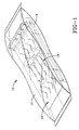
- FIGURE 1 With reference to FIGURE 1, there is shown a T-fastener installation kit 10 which is enclosed within a sealed clear plastic wrapper 11.
- the wrapper 11 encloses a packaging device 13, which contains plurality of T-fasteners 19, and a slotted needle 18 which is necessary for installing the T-fasteners 19.
- the wrapper 11 may comprise any suitable material that is capable of surviving a sterilization procedure, such as high temperatures or ethylene oxide, and may be either transparent or opaque.
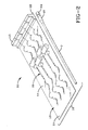
- the T-fastener installation kit 10 is shown with the plastic wrapper removed. It can be seen that a preferred embodiment of a kit 10 comprises the packaging device 13, a plurality of T-fasteners 19, preferably at least four, and a slotted needle 18 having a shaft portion which is disposed within a protective sheath 7. A stylet 64 is provided in assembly with the slotted needle 18 such that a portion of the stylet is disposed within the bore of the slotted needle.
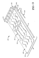
- four T-fasteners 19 are generally used in a surgical procedure it is preferred, as shown in FIGURE 3, that an extra T-fastener 19 be included in the T-fastener installation kit 10 in case a T-fastener 19 is broken, dropped, or otherwise becomes unusable during the surgical procedure.
- the packaging device 13 could be adapted to accommodate five T-fastener assemblies, or in fact any desired number of T-fastener assemblies.
- the packaging device 13 comprises a substantially planar base 14 and a housing 15.
- the base 14 has a first end 22 and a second end 24.
- the housing 15 is fixedly attached to the base 14 in close proximity to the first end 22 of the base.
- the base 14 is made of cardboard while the housing 15 is made of a plastic material such as a polycarbonate. It is understood that any suitable material, or materials, may be employed in the packaging device and that the base and housing may be molded integrally, or made separately and then attached to one another by suitable means for attachment such as an adhesive, tabs and slots, or mechanical fasteners.
- Each T-fastener 19 comprises a "T" head 45 and a suture 46.
- the suture 46 has a first end 50, at which end the "T" head 45 is located, and a second end 52. Threaded onto the suture 46 is a compressible pledget 47, a retention disk or washer 48 and one or more crimpable clamping elements 49.
- the "T" head 45 is preferably an elongated stainless steel cylinder, which is affixed to one end 50 of a suture 46, which is preferably formed of nylon.
- the pledget 47 is preferably formed of a soft, absorbent material such as cotton or methylcellulose, and acts as a cushion against the skin and as an absorbent for fluids.
- the compression applying tension disk or washer 48 is preferably formed of nylon, and the crimpable clamping devices 19 are preferably formed of aluminum. It is understood that the exact components of a T-fastener may be varied in terms of materials and configurations.
- a "T-fastener” is understood to be a percutaneous fixation device suitable to fix the position of a hollow organ within a body, comprising: a "T” head comprising a stiff member, an elongated, relatively more flexible primary tension filament secured at the mid-region of said "T” head, said elongated primary tension filament having a free end trailing back from said "T” head, and compressible means threaded on said elongated primary tension filament for bearing in a cushioning manner with compression against the skin of the body, and means for pressing upon said compressible means while clamping said primary tension member to apply tension to said primary tension filament to draw said "T" head against the inner surface of the hollow organ.
- the slotted needle 18 has a sharp beveled tip 56, a longitudinal slot 70 associated with the tip, a length suitable to permit percutaneous insertion, and has a bore 72 therethrough with a diameter large enough to accept a "T" head 45 so that the "T" head is entirely within the needle when the needle is thrust through flesh into the interior of a hollow organ.
- the longitudinal slot 70 extends parallel to the longitudinal axis of the bore which extends through the entire length of the slotted needle.
- the slotted needle has indicia 73 located on its outer surface to indicate the depth of insertion of the needle.
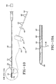
- a stylet 64 is disposed within the bore 72 of the needle, and when a T-fastener is loaded in the needle (FIGURE 10A) one end 66 of the stylet is near or touching the "T" head and the other end of the stylet extends through the hub of the slotted needle.
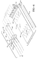
- the T-fasteners 19 are shown, ready to be loaded into the packaging device 13.
- the "T” heads 45 of the T-fasteners 19 are oriented perpendicularly to the sutures 46, as is their normal, relaxed position.
- the "T” heads 45 are inserted into cylindrical recesses 26 in the housing 15.
- Each suture 46 is extended through a notch 38 in the housing and threaded under cutouts 28 in the base 14.
- the cutouts 28 are generally semicircular perforations in the base 14 which can be selectively elastically deformed outwardly from the base 14 to receive and retain the sutures 46.
- the T-fasteners 19 assembled with the packaging device 13 are shown in FIGURES 2 and 3.
- the housing 15 comprises in a vertical cross-section a first generally rectangular section 30 which is coupled to a second generally rectangular section 32 to form a "step" shaped or “L” shaped configuration.
- the second rectangular section 32 would be unnecessary and might be eliminated as a cost reduction measure.
- terms such as “vertical”, “horizontal”, “upper”, “lower”, “top”, and “bottom” are understood to refer to a packaging device 13 having its substantially planar base 14 resting on a flat horizontal surface such that the housing 15 extends upwardly with respect to said flat horizontal surface.
- a top surface 34 of the housing 15 features cylindrically-shaped recesses 26 which extend vertically into the housing 15. That is to say, the housing 15 has cylindrically-shaped wells 26 therein which are open at the top surface 34 of the housing.
- Each of these cylindrical recesses 26 has an inside diameter which is slightly larger than the outside diameter of the "T" heads 45 of the T-fasteners 19. With regard to both the cylindrical recesses 26 and the "T" heads 45, the respective diameters are measured across the smallest dimension of the item, as is usual.
- a notch 38 in the housing 15 communicates with the cylindrical recess 26.
- the notch 38 is generally parallel to the longitudinal axis of the cylindrical recess 26.
- the T-fastener suture 46 extends through a notch 38.
- the top surface 34 of the housing 15 features a bevelled portion 40 encircling each cylindrical recess 26 to assist a surgeon, or his assistant, in directing the sharp end 56 of the slotted needle 18 into the cylindrical recess 26.
- the outer surfaces of the housing 15 preferably have rounded corners 42. One of the advantages of such rounded corners 42 is a reduction in the possibility of a sharp corner piercing the wrapper and contaminating the contents of the T-fastener kit 10.
- the housing 15 features hollow areas 60 on its underside. These hollow areas 60 strengthen the structural rigidity of the housing 15 while also contributing to weight and material savings.
- the second rectangular section 32 performs the function of lifting the suture 46 above the surface of the base 14. Because the surgeon or assistant will undoubtedly be wearing latex gloves, this lifting of the suture 46 assists in removing a suture 46 from the base 14 and cutouts 28. A finger can be slipped between the rectangular section 32 and the base 14 to grip the suture 46.
- the packaging device 13 functions not only to maintain the T-fasteners in an orderly untangled configuration during sterilization, shipping and storage, but also functions as a means of facilitating the efficient loading of the T-fasteners in a slotted needle.
- the slotted needle 18 is used in conjunction with a stylet 64.
- the stylet 64 is inserted into the second end 68 of the slotted needle 18 (commonly referred to as the "hub" of the needle) and used to push the T-fastener 19 from the slotted needle 18 and into a hollow organ within a patient.
- a first end 66 of the stylet 64 can be seen in FIGURE 6.
- the first end 66 of the stylet contacts the "T" head 45 of the T-fastener 19. This is accomplished by the surgeon 53 applying pressure to the other end of the stylet 64 with a thumb or finger.
- the surgeon, or assistant, 53 grips the slotted needle 18 and lowers the sharpened end 56 of the slotted needle into a cylindrical recess 26 which contains the "T" head of a T-fastener.
- a longitudinally extending slot 70 in the sharp end 56 of the slotted needle 18 is aligned with the notch 38 in the housing 15 which communicates with the cylindrical recess 26.
- the "T" head 45 of the T-fastener and the first end 50 of the suture 46 are received into the bore of the slotted needle 18.
- the inside diameter of the bore of the slotted needle 18 is slightly greater than the outside diameter of the "T" head 45 of the T-fastener 19 and the outside diameter of the slotted needle is slightly less than the inside diameter of the cylindrical recess 26. As such, the "T" head 45 of the T-fastener 19 can be received into the bore of the slotted needle 18, with the suture of the T-fastener extending through the longitudinal slot 70 in the needle.
- the next step of loading a T-fastener 19 into the slotted needle 18 is illustrated.
- the surgeon, or his assistant grips the second end 52 of the suture 46 and carefully removes the suture 46 from the cutouts 28 in the base 14 of the packaging device.
- the suture 46 is free, the second end 52 of the suture 46 and other elements of the T-fastener 19 are lifted away from the base 14, the suture is extended along the exterior of the slotted needle and is gripped near the second end 68 of the slotted needle 18.
- the surgeon 53 then lifts the slotted needle 18 from the housing 15. With the T-fastener 19 loaded therein, ready for installation in the body of a patient.
Landscapes
- Health & Medical Sciences (AREA)
- Life Sciences & Earth Sciences (AREA)
- Surgery (AREA)
- Molecular Biology (AREA)
- General Health & Medical Sciences (AREA)
- Biomedical Technology (AREA)
- Heart & Thoracic Surgery (AREA)
- Medical Informatics (AREA)
- Nuclear Medicine, Radiotherapy & Molecular Imaging (AREA)
- Animal Behavior & Ethology (AREA)
- Engineering & Computer Science (AREA)
- Public Health (AREA)
- Veterinary Medicine (AREA)
- Dentistry (AREA)
- Rheumatology (AREA)
- Surgical Instruments (AREA)
- Packaging Of Annular Or Rod-Shaped Articles, Wearing Apparel, Cassettes, Or The Like (AREA)
- Supplying Of Containers To The Packaging Station (AREA)
- Basic Packing Technique (AREA)
Abstract
Description
- The present invention relates to surgical instruments, and more particularly to T-shaped tension members used in surgical procedures, and even more particularly to a device for packaging these T-shaped tension members and loading them into a slotted needle without requiring a person's hands to handle or come near the sharp end of the slotted needle.
- U.S. Patent No. Re. 34,021 discloses a method and apparatus for fixing a hollow organ of a living body to a body wall using T-shaped tension members (hereinafter referred to as T-fasteners). Examples of surgical procedures which may utilize the teachings of Re. 34,021 are securing a patient's stomach or bowel in apposition to the abdominal wall, such as in a gastrostomy or jejunostomy procedure. These procedures are performed to facilitate the insertion of a feeding tube through the abdominal wall directly into the stomach or bowel. Examples of individuals who may require such a procedure includes burn patients, whose daily caloric needs are very high; critically ill, weak or comatose patients who may be unable to swallow food; and patients suffering from a diseased or traumatized esophagus, who may be unable to swallow food. Increasingly, a new class of persons requiring such treatment include patients infected with the HIV virus.
- A relatively new method of placing a gastrostomy tube or jejunostomy tube is described in U.S. Patent 5,151,086. In this patent, a laparoscopic procedure is described which utilizes instruments and equipment which passes through the skin and surrounding tissue to the surgical site. The laparoscopic procedures require the use of many instruments and supplies including a nasogastric tube, scalpel, needles, syringes, T-fasteners, a J-guide wire, dilators, a gastrostomy tube, stylet, and water-soluble lubricant.
- USP 3,696,920 discloses a device for organizing surgical instruments comprising a block containing channels for retaining surgical instruments therein, beveled slots providing communication between the surface of the block and the channels and means for securing the block to a supporting surface.
- USP 5,078,730 discloses a holder for a suture assembly comprising a suture attached to a suture anchor and comprising a surgical needle attached to the suture, the holder comprising a body, suture anchor holder means for holding the suture anchor to the body comprising a channel formed in the body for receiving the suture anchor therein, suture holding means for holding the suture to the body, needle holder means and covering means.
- In the procedure to be described later herein, a "T" head of a T-fastener is inserted into a slotted needle. Because several T-fasteners may be installed during a surgical procedure with the same needle, it is required that a surgeon, or an assistant, repeatedly load T-fasteners into the needle. The risk of a surgeon, or an assistant, inadvertently pricking his finger(s), and thereby enhancing the possibility of transmitting a disease between a member of the surgical team and the patient, or vice versa, with a needle can be reduced by the method and apparatus for loading the T-fastener assemblies into the slotted needle disclosed herein. The apparatus of the present invention allow a "T" head of a T-fastener to be loaded into a slotted needle without the surgeon, or an assistant, having to touch the slotted needle near its point, thus reducing the chance of inadvertently pricking his finger.
- The features of the present invention which are believed to be novel or set forth with particularity in the appended claims. The present invention, both as to its structure and manner of operation, may best be understood by referring to the following detailed description, taken in accordance with the accompanying drawings in which:
- FIGURE 1 is a perspective view of an unopened T-fastener installation kit of the present invention;
- FIGURE 2 is a perspective view of the T-fastener installation kit of FIGURE 1 with the outer wrapping removed, showing that the kit comprises a packaging device, T-fasteners and a slotted needle within a protective sleeve;
- FIGURE 3 is a perspective view of a T-fastener installation kit of an alternative embodiment with the outer wrapping removed, having a T-fastener pre-loaded in the slotted needle;
- FIGURE 4 is an exploded view of the contents of the packaging device, showing the T-fasteners and their relation to the packaging device;
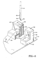
- FIGURE 5 illustrates the procedure whereby a "T" head of a T-fastener can be loaded into the pointed end of a slotted needle;
- FIGURE 6 is a enlarged view of a portion of FIGURE 5, showing the orientation of the "T" head of the T-fastener within the loading device of the invention;
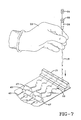
- FIGURE 7 illustrates a step in the procedure whereby the "T" head of a T-fastener can be loaded into the pointed end of a slotted needle;
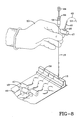
- FIGURE 8 illustrates a subsequent step of the procedure illustrated in FIGURE 7;
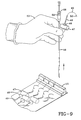
- FIGURE 9 illustrates a subsequent step of the procedure illustrated in FIGURES 7 and 8;
- FIGURE 10 illustrates a T-fastener which has been loaded into a slotted needle, ready for installation into a patient; and
- FIGURE 10A is an enlarged view of a portion of FIGURE 10, partially broken away.
-
- With reference to FIGURE 1, there is shown a T-
fastener installation kit 10 which is enclosed within a sealed clearplastic wrapper 11. Thewrapper 11 encloses apackaging device 13, which contains plurality of T-fasteners 19, and aslotted needle 18 which is necessary for installing the T-fasteners 19. It is understood that thewrapper 11 may comprise any suitable material that is capable of surviving a sterilization procedure, such as high temperatures or ethylene oxide, and may be either transparent or opaque. - With reference to FIGURE 2, the T-
fastener installation kit 10 is shown with the plastic wrapper removed. It can be seen that a preferred embodiment of akit 10 comprises thepackaging device 13, a plurality of T-fasteners 19, preferably at least four, and a slottedneedle 18 having a shaft portion which is disposed within aprotective sheath 7. Astylet 64 is provided in assembly with theslotted needle 18 such that a portion of the stylet is disposed within the bore of the slotted needle. Although four T-fasteners 19 are generally used in a surgical procedure it is preferred, as shown in FIGURE 3, that an extra T-fastener 19 be included in the T-fastener installation kit 10 in case a T-fastener 19 is broken, dropped, or otherwise becomes unusable during the surgical procedure. While the fifth T-fastener is shown pre-loaded into the slotted needle, with aprotective sheath 7 over the shaft of the needle, it is understood that thepackaging device 13, could be adapted to accommodate five T-fastener assemblies, or in fact any desired number of T-fastener assemblies. - With reference to the embodiments of both FIGURES 2 and 3, the
packaging device 13 comprises a substantiallyplanar base 14 and ahousing 15. Thebase 14 has afirst end 22 and asecond end 24. Thehousing 15 is fixedly attached to thebase 14 in close proximity to thefirst end 22 of the base. In a currently preferred embodiment, thebase 14 is made of cardboard while thehousing 15 is made of a plastic material such as a polycarbonate. It is understood that any suitable material, or materials, may be employed in the packaging device and that the base and housing may be molded integrally, or made separately and then attached to one another by suitable means for attachment such as an adhesive, tabs and slots, or mechanical fasteners. - With reference to FIGURES 4 and 10, the components of a T-
fastener 19 will be described. Each T-fastener 19 comprises a "T"head 45 and asuture 46. Thesuture 46 has afirst end 50, at which end the "T"head 45 is located, and asecond end 52. Threaded onto thesuture 46 is acompressible pledget 47, a retention disk orwasher 48 and one or morecrimpable clamping elements 49. The "T"head 45 is preferably an elongated stainless steel cylinder, which is affixed to oneend 50 of asuture 46, which is preferably formed of nylon. Thepledget 47 is preferably formed of a soft, absorbent material such as cotton or methylcellulose, and acts as a cushion against the skin and as an absorbent for fluids. The compression applying tension disk orwasher 48 is preferably formed of nylon, and thecrimpable clamping devices 19 are preferably formed of aluminum. It is understood that the exact components of a T-fastener may be varied in terms of materials and configurations. Therefore, as used herein and in the claims a "T-fastener" is understood to be a percutaneous fixation device suitable to fix the position of a hollow organ within a body, comprising: a "T" head comprising a stiff member, an elongated, relatively more flexible primary tension filament secured at the mid-region of said "T" head, said elongated primary tension filament having a free end trailing back from said "T" head, and compressible means threaded on said elongated primary tension filament for bearing in a cushioning manner with compression against the skin of the body, and means for pressing upon said compressible means while clamping said primary tension member to apply tension to said primary tension filament to draw said "T" head against the inner surface of the hollow organ. - With reference to FIGURES 4, 10 and 10A the
slotted needle 18 has a sharpbeveled tip 56, alongitudinal slot 70 associated with the tip, a length suitable to permit percutaneous insertion, and has abore 72 therethrough with a diameter large enough to accept a "T"head 45 so that the "T" head is entirely within the needle when the needle is thrust through flesh into the interior of a hollow organ. Thelongitudinal slot 70 extends parallel to the longitudinal axis of the bore which extends through the entire length of the slotted needle. - Also, as shown, the slotted needle has
indicia 73 located on its outer surface to indicate the depth of insertion of the needle. Astylet 64 is disposed within thebore 72 of the needle, and when a T-fastener is loaded in the needle (FIGURE 10A) oneend 66 of the stylet is near or touching the "T" head and the other end of the stylet extends through the hub of the slotted needle. - With reference to FIGURE 4, the T-
fasteners 19 are shown, ready to be loaded into thepackaging device 13. The "T"heads 45 of the T-fasteners 19 are oriented perpendicularly to thesutures 46, as is their normal, relaxed position. The "T"heads 45 are inserted intocylindrical recesses 26 in thehousing 15. Eachsuture 46 is extended through anotch 38 in the housing and threaded undercutouts 28 in thebase 14. Thecutouts 28 are generally semicircular perforations in thebase 14 which can be selectively elastically deformed outwardly from thebase 14 to receive and retain thesutures 46. The T-fasteners 19 assembled with thepackaging device 13 are shown in FIGURES 2 and 3. - With reference to FIGURES 5 and 6, the
innovative housing 15 will be described. In a currently preferred embodiment, thehousing 15 comprises in a vertical cross-section a first generallyrectangular section 30 which is coupled to a second generallyrectangular section 32 to form a "step" shaped or "L" shaped configuration. In other embodiments, it is foreseeable that the secondrectangular section 32 would be unnecessary and might be eliminated as a cost reduction measure. As used herein and in the claims, terms such as "vertical", "horizontal", "upper", "lower", "top", and "bottom" are understood to refer to apackaging device 13 having its substantiallyplanar base 14 resting on a flat horizontal surface such that thehousing 15 extends upwardly with respect to said flat horizontal surface. Atop surface 34 of thehousing 15 features cylindrically-shapedrecesses 26 which extend vertically into thehousing 15. That is to say, thehousing 15 has cylindrically-shapedwells 26 therein which are open at thetop surface 34 of the housing. Each of thesecylindrical recesses 26 has an inside diameter which is slightly larger than the outside diameter of the "T" heads 45 of the T-fasteners 19. With regard to both thecylindrical recesses 26 and the "T" heads 45, the respective diameters are measured across the smallest dimension of the item, as is usual. - As can be seen most clearly in FIGURE 5, a
notch 38 in thehousing 15 communicates with thecylindrical recess 26. Thenotch 38 is generally parallel to the longitudinal axis of thecylindrical recess 26. When the "T"head 45 of a T-fastener 19 is correctly loaded into thehousing 15, the T-fastener suture 46 extends through anotch 38. In the preferred embodiment, as can be seen most clearly in FIGURE 6, thetop surface 34 of thehousing 15 features a bevelledportion 40 encircling eachcylindrical recess 26 to assist a surgeon, or his assistant, in directing thesharp end 56 of the slottedneedle 18 into thecylindrical recess 26. The outer surfaces of thehousing 15 preferably have roundedcorners 42. One of the advantages of suchrounded corners 42 is a reduction in the possibility of a sharp corner piercing the wrapper and contaminating the contents of the T-fastener kit 10. - In a preferred embodiment the
housing 15 featureshollow areas 60 on its underside. Thesehollow areas 60 strengthen the structural rigidity of thehousing 15 while also contributing to weight and material savings. The secondrectangular section 32 performs the function of lifting thesuture 46 above the surface of thebase 14. Because the surgeon or assistant will undoubtedly be wearing latex gloves, this lifting of thesuture 46 assists in removing asuture 46 from thebase 14 andcutouts 28. A finger can be slipped between therectangular section 32 and the base 14 to grip thesuture 46. - It is an important feature of the present invention that the
packaging device 13 functions not only to maintain the T-fasteners in an orderly untangled configuration during sterilization, shipping and storage, but also functions as a means of facilitating the efficient loading of the T-fasteners in a slotted needle. - With reference to FIGURES 6-9, the method of loading a T-
fastener 19 in a slottedneedle 18 will be illustrated. The slottedneedle 18 is used in conjunction with astylet 64. Thestylet 64 is inserted into thesecond end 68 of the slotted needle 18 (commonly referred to as the "hub" of the needle) and used to push the T-fastener 19 from the slottedneedle 18 and into a hollow organ within a patient. Afirst end 66 of thestylet 64 can be seen in FIGURE 6. Thefirst end 66 of the stylet contacts the "T"head 45 of the T-fastener 19. This is accomplished by thesurgeon 53 applying pressure to the other end of thestylet 64 with a thumb or finger. - With particular reference to FIGURES 6 and 7, the method of loading the T-
fastener 19 into the slottedneedle 18 will now be explained. With one hand the surgeon, or assistant, 53 grips the slottedneedle 18 and lowers the sharpenedend 56 of the slotted needle into acylindrical recess 26 which contains the "T" head of a T-fastener. As can be best seen in FIGURE 6, a longitudinally extendingslot 70 in thesharp end 56 of the slottedneedle 18 is aligned with thenotch 38 in thehousing 15 which communicates with thecylindrical recess 26. As such, the "T"head 45 of the T-fastener and thefirst end 50 of thesuture 46 are received into the bore of the slottedneedle 18. The inside diameter of the bore of the slottedneedle 18 is slightly greater than the outside diameter of the "T"head 45 of the T-fastener 19 and the outside diameter of the slotted needle is slightly less than the inside diameter of thecylindrical recess 26. As such, the "T"head 45 of the T-fastener 19 can be received into the bore of the slottedneedle 18, with the suture of the T-fastener extending through thelongitudinal slot 70 in the needle. - With reference to FIGURE 8, the next step of loading a T-
fastener 19 into the slottedneedle 18 is illustrated. With his other hand (the hand not gripping the slotted needle 18), the surgeon, or his assistant, 53 grips thesecond end 52 of thesuture 46 and carefully removes thesuture 46 from thecutouts 28 in thebase 14 of the packaging device. After thesuture 46 is free, thesecond end 52 of thesuture 46 and other elements of the T-fastener 19 are lifted away from thebase 14, the suture is extended along the exterior of the slotted needle and is gripped near thesecond end 68 of the slottedneedle 18. - With reference to FIGURE 9, the
surgeon 53 then lifts the slottedneedle 18 from thehousing 15. With the T-fastener 19 loaded therein, ready for installation in the body of a patient. - The foregoing description is for purposes of illustration rather than limitation of the scope of protection of this invention. The latter is to be measured by the following claims, which should be interpreted as broadly as the invention permits.
Claims (9)
- An assembly of a T-fastener (19) and a device (13) for loading a T-fastener (19) into a needle (18), said T-fastener comprising a "T" head (45) and a suture (46) attached thereto, said device comprising a generally planar base (14) and a housing (15) attached thereto, said housing having a recess (26) therein which contains the "T" head (45) of the T-fastener (19), said recess having a longitudinal axis, a first end and a second end, the first end of said recess (26) being open at a top surface (34) of the housing and the second end of recess being a solid surface of the housing , the longitudinal axis of the recess and the "T" head (45) of the "T" fastener (19) both being oriented generally vertically with respect to said base (14), said housing (15) having a notch (38) therein which communicates with said recess (26) and is generally parallel to the longitudinal axis of said recess (26), the suture (46) of said T-fastener (19) exstending through said notch (38) and being secured to said generally planar base (14) by means for securing (28).
- The assembly of claim 1 wherein said housing (15) has a plurality of recesses (26) and notches (38) therein having the features of the recess and notch described in claim 1, and further comprising an equivalent number of T-fasteners (19) which are disposed in the manner described in claim 1.
- The assembly of either of claims 1 or 2 wherein said recess (26) is cylindrical.
- The assembly of any of the preceding claims wherein the top surface (34) of the housing (15) surrounding each cylindrical recess (26) is beveled inwardly towards the cylindrical recess (26).
- The assembly of any claims 1 through 4 wherein said housing has a vertical cross section which is rectangular.
- The assembly of any of claims 1-4 wherein said housing has a vertical cross-section which is L-shaped.
- The assembly of any of the preceding claims wherein the means for securing the sutures to the generally planar base comprises portions (28) of the base (14) which are foldable upwardly from the base for receiving the sutures (46) thereunder.
- The assembly of any of the preceding claims wherein said housing (15) comprises plastic and said base (14) comprises cardboard.
- The assembly of any of the preceding claims in combination with a slotted needle (18) having a bore (72) therethrough for receiving the "T" head (45) of the T-fastener (19) therein and means for displacing a "T" head (45) of a T-fastener (19) from the bore of said slotted needle, and a wrapper which contains all of the components of said assembly, said slotted needle (18) and said means for displacing.
Applications Claiming Priority (3)
| Application Number | Priority Date | Filing Date | Title |
|---|---|---|---|
| US08/038,751 US5307924A (en) | 1993-03-26 | 1993-03-26 | Packaging for T-shaped tension devices |
| US38751 | 1993-03-26 | ||
| PCT/US1994/002728 WO1994022381A1 (en) | 1993-03-26 | 1994-03-14 | Packaging for t-shaped tension devices |
Publications (3)
| Publication Number | Publication Date |
|---|---|
| EP0746239A4 EP0746239A4 (en) | 1996-06-04 |
| EP0746239A1 EP0746239A1 (en) | 1996-12-11 |
| EP0746239B1 true EP0746239B1 (en) | 2002-09-04 |
Family
ID=21901687
Family Applications (1)
| Application Number | Title | Priority Date | Filing Date |
|---|---|---|---|
| EP94911585A Expired - Lifetime EP0746239B1 (en) | 1993-03-26 | 1994-03-14 | Packaging for t-shaped tension devices |
Country Status (7)
| Country | Link |
|---|---|
| US (2) | US5307924A (en) |
| EP (1) | EP0746239B1 (en) |
| AU (1) | AU673914B2 (en) |
| CA (1) | CA2143645C (en) |
| DE (1) | DE69431309T2 (en) |
| ES (1) | ES2185648T3 (en) |
| WO (1) | WO1994022381A1 (en) |
Cited By (5)
| Publication number | Priority date | Publication date | Assignee | Title |
|---|---|---|---|---|
| US7875042B2 (en) | 2007-05-04 | 2011-01-25 | Ethicon Endo-Surgery, Inc. | Suture anchor loader |
| US8821520B2 (en) | 2007-05-04 | 2014-09-02 | Ethicon Endo-Surgery, Inc. | Loader for knotting element |
| US8992547B2 (en) | 2012-03-21 | 2015-03-31 | Ethicon Endo-Surgery, Inc. | Methods and devices for creating tissue plications |
| US9113879B2 (en) | 2011-12-15 | 2015-08-25 | Ethicon Endo-Surgery, Inc. | Devices and methods for endoluminal plication |
| US9113867B2 (en) | 2011-12-15 | 2015-08-25 | Ethicon Endo-Surgery, Inc. | Devices and methods for endoluminal plication |
Families Citing this family (70)
| Publication number | Priority date | Publication date | Assignee | Title |
|---|---|---|---|---|
| US5566822A (en) * | 1993-12-09 | 1996-10-22 | United States Surgical Corporation | Suture retainer |
| US5478345A (en) * | 1994-08-19 | 1995-12-26 | United States Surgical Corporation | Mechanism for endoscopic suturing device |
| US5531699A (en) * | 1994-09-19 | 1996-07-02 | Abbott Laboratories | Spring-loaded reciprocable stylet holder |
| WO1996032893A1 (en) * | 1995-04-21 | 1996-10-24 | W.L. Gore & Associates, Inc. | A surgical pledget dispensing system |
| US5662658A (en) * | 1996-01-19 | 1997-09-02 | Mitek Surgical Products, Inc. | Bone anchor inserter, method for loading same, method for holding and delivering a bone anchor, and method for inserting a bone anchor in a bone |
| US6077250A (en) * | 1997-10-01 | 2000-06-20 | Boston Scientific Corporation | Apparatus and method for percutaneously placing gastrostomy tubes |
| US6315789B1 (en) | 1999-02-08 | 2001-11-13 | Andrew H. Cragg | Medical device anchoring system and method |
| US9072543B2 (en) | 2002-05-31 | 2015-07-07 | Vidacare LLC | Vascular access kits and methods |
| WO2008033873A2 (en) | 2006-09-12 | 2008-03-20 | Vidacare Corporation | Medical procedures trays and related methods |
| US20070049945A1 (en) | 2002-05-31 | 2007-03-01 | Miller Larry J | Apparatus and methods to install, support and/or monitor performance of intraosseous devices |
| US9545243B2 (en) | 2002-05-31 | 2017-01-17 | Vidacare LLC | Bone marrow aspiration devices and related methods |
| EP3292821A1 (en) | 2002-05-31 | 2018-03-14 | Vidacare LLC | Apparatus and method to access bone marrow |
| US11298202B2 (en) | 2002-05-31 | 2022-04-12 | Teleflex Life Sciences Limited | Biopsy devices and related methods |
| US8668698B2 (en) | 2002-05-31 | 2014-03-11 | Vidacare Corporation | Assembly for coupling powered driver with intraosseous device |
| US7951089B2 (en) | 2002-05-31 | 2011-05-31 | Vidacare Corporation | Apparatus and methods to harvest bone and bone marrow |
| US11337728B2 (en) | 2002-05-31 | 2022-05-24 | Teleflex Life Sciences Limited | Powered drivers, intraosseous devices and methods to access bone marrow |
| US10973545B2 (en) | 2002-05-31 | 2021-04-13 | Teleflex Life Sciences Limited | Powered drivers, intraosseous devices and methods to access bone marrow |
| WO2008033874A2 (en) | 2006-09-12 | 2008-03-20 | Vidacare Corporation | Bone marrow aspiration devices and related methods |
| WO2008033871A2 (en) | 2006-09-12 | 2008-03-20 | Vidacare Corporation | Apparatus and methods for biopsy and aspiration of bone marrow |
| US7811260B2 (en) | 2002-05-31 | 2010-10-12 | Vidacare Corporation | Apparatus and method to inject fluids into bone marrow and other target sites |
| US10973532B2 (en) | 2002-05-31 | 2021-04-13 | Teleflex Life Sciences Limited | Powered drivers, intraosseous devices and methods to access bone marrow |
| US8641715B2 (en) | 2002-05-31 | 2014-02-04 | Vidacare Corporation | Manual intraosseous device |
| US8690791B2 (en) | 2002-05-31 | 2014-04-08 | Vidacare Corporation | Apparatus and method to access the bone marrow |
| US9314228B2 (en) | 2002-05-31 | 2016-04-19 | Vidacare LLC | Apparatus and method for accessing the bone marrow |
| AU2003256503A1 (en) * | 2002-07-17 | 2004-02-09 | Tyco Healthcare Group Lp | Suture pledget package |
| DE10244315B4 (en) * | 2002-09-23 | 2006-01-05 | Groz-Beckert Kg | Tool carrier for sliding needles and shipping unit |
| AU2003299086B2 (en) * | 2002-09-24 | 2008-08-07 | Ethicon Endo-Surgery, Inc. | Ultrasonic surgical instrument having an increased working length |
| US6966916B2 (en) * | 2002-09-26 | 2005-11-22 | Kumar Sarbjeet S | Device and method for surgical repair of abdominal wall hernias |
| US9504477B2 (en) | 2003-05-30 | 2016-11-29 | Vidacare LLC | Powered driver |
| US7815642B2 (en) | 2004-01-26 | 2010-10-19 | Vidacare Corporation | Impact-driven intraosseous needle |
| ATE425705T1 (en) | 2004-01-26 | 2009-04-15 | Vidacare Corp | MANUAL INTEROSSARY DEVICE |
| DE102004006398B4 (en) * | 2004-02-10 | 2006-06-08 | Atmel Germany Gmbh | Method and device for synchronizing a functional unit to a predetermined clock frequency |
| US7328794B2 (en) * | 2004-03-05 | 2008-02-12 | Boston Scientific Scimed, Inc. | Packaging for elongate medical devices and methods of manufacture and use thereof |
| US7654980B2 (en) * | 2004-05-14 | 2010-02-02 | Boston Scientific Scimed, Inc. | Method for percutaneously implanting a medical catheter and medical catheter implanting assembly |
| US20050288689A1 (en) * | 2004-06-25 | 2005-12-29 | Kammerer Gene W | Applicator and method for deploying a surgical fastener |
| US7452368B2 (en) * | 2004-09-15 | 2008-11-18 | Ethicon, Inc. | System for holding surgical fasteners |
| US8998848B2 (en) | 2004-11-12 | 2015-04-07 | Vidacare LLC | Intraosseous device and methods for accessing bone marrow in the sternum and other target areas |
| US20070227916A1 (en) * | 2006-04-04 | 2007-10-04 | Stan Malinowski | Steel suture package |
| WO2007121383A2 (en) * | 2006-04-13 | 2007-10-25 | Solopower, Inc. | Method and apparatus to form thin layers of materials on a base |
| US7758598B2 (en) * | 2006-05-19 | 2010-07-20 | Ethicon Endo-Surgery, Inc. | Combination knotting element and suture anchor applicator |
| US8944069B2 (en) | 2006-09-12 | 2015-02-03 | Vidacare Corporation | Assemblies for coupling intraosseous (IO) devices to powered drivers |
| US7674275B2 (en) * | 2006-10-05 | 2010-03-09 | Ethicon Endo-Surgery, Inc. | Suture anchor |
| US20080103527A1 (en) * | 2006-10-27 | 2008-05-01 | Martin David T | Flexible endoscopic suture anchor applier |
| US8974410B2 (en) | 2006-10-30 | 2015-03-10 | Vidacare LLC | Apparatus and methods to communicate fluids and/or support intraosseous devices |
| WO2008124463A2 (en) | 2007-04-04 | 2008-10-16 | Vidacare Corporation | Powered drivers, intraosseous devices and methods to access bone marrow |
| US7867253B2 (en) * | 2007-08-31 | 2011-01-11 | Kimberly-Clark Worldwide, Inc. | Suture retention hub |
| US20090062742A1 (en) | 2007-08-31 | 2009-03-05 | John Anthony Rotella | Blunted Safety Needle |
| US8157816B2 (en) * | 2007-08-31 | 2012-04-17 | Kimberly-Clark Worldwide, Inc. | Gastropexy kit |
| US8287556B2 (en) * | 2008-06-17 | 2012-10-16 | Apollo Endosurgery, Inc. | Endoscopic suturing system |
| US11812951B2 (en) | 2008-06-17 | 2023-11-14 | Apollo Endosurgery Us, Inc. | Endoscopic needle assembly |
| US8679136B2 (en) | 2008-06-17 | 2014-03-25 | Apollo Endosurgery, Inc. | Needle capture device |
| US11083364B2 (en) | 2008-06-17 | 2021-08-10 | Apollo Endosurgery Us, Inc. | Endoscopic tissue grasping systems and methods |
| US8011499B2 (en) * | 2008-12-16 | 2011-09-06 | Ethicon, Inc. | Suture tray package |
| CA2758888A1 (en) * | 2009-04-17 | 2010-10-21 | Cook Medical Technologies Llc | Suture anchor loading device |
| DK200970073A (en) * | 2009-07-22 | 2011-01-23 | Coloplast As | Suturing system and assembly |
| US20110046642A1 (en) * | 2009-08-21 | 2011-02-24 | Coloplast A/S | Suture assembly and system |
| US9592044B2 (en) | 2011-02-09 | 2017-03-14 | C. R. Bard, Inc. | T-fastener suture delivery system |
| US20120240378A1 (en) * | 2011-03-24 | 2012-09-27 | Boston Scientific Scimed, Inc. | Loader for implant delivery tools and methods of using the same |
| US9301825B2 (en) | 2011-07-06 | 2016-04-05 | Boston Scientific Scimed, Inc. | Bodily implants formed from different materials |
| US8992550B2 (en) | 2011-07-20 | 2015-03-31 | Coloplast A/S | Suture system with capsule eyelet providing multiple suture tissue fixation |
| US9084596B2 (en) * | 2012-02-27 | 2015-07-21 | Cook Medical Technologies Llc | Suture clamp and gastrointestinal suture anchor set device using same |
| US9427228B2 (en) * | 2012-11-09 | 2016-08-30 | Karl Storz Gmbh & Co. Kg | Suture cartridge for meniscal repair |
| JP6108476B2 (en) * | 2014-05-10 | 2017-04-05 | 朝日インテック株式会社 | Mount |
| US10098628B2 (en) | 2014-07-22 | 2018-10-16 | Cook Medical Technologies Llc | Anchor deployment system, device, and method of treatment |
| US9480565B2 (en) | 2015-02-02 | 2016-11-01 | On-X Life Technologies, Inc. | Rapid deployment artificial chordae tendinae system |
| US11103350B2 (en) | 2016-06-01 | 2021-08-31 | On-X Life Technologies, Inc. | Pull-through chordae tendineae system |
| US11141147B2 (en) | 2016-08-10 | 2021-10-12 | Apollo Endosurgery Us, Inc. | Endoscopic suturing system having external instrument channel |
| US11051800B2 (en) | 2016-08-10 | 2021-07-06 | Apollo Endosurgery Us, Inc. | Endoscopic suturing system having external instrument channel |
| CN108125696A (en) * | 2017-12-20 | 2018-06-08 | 江苏省健尔康医用敷料有限公司 | Anti-dropout medical sutures box for needle or pin |
| US11191603B1 (en) * | 2021-03-09 | 2021-12-07 | Cynthia Schor | Surgical tool support system |
Family Cites Families (16)
| Publication number | Priority date | Publication date | Assignee | Title |
|---|---|---|---|---|
| US2747574A (en) * | 1954-09-29 | 1956-05-29 | Lorenzo Joseph P De | Disposable package and applicator for suppositories |
| US3206018A (en) * | 1963-07-10 | 1965-09-14 | Ethicon Inc | Wire suturing device |
| US3696920A (en) * | 1970-10-15 | 1972-10-10 | Int Paper Co | Device for organizing objects |
| US3779375A (en) * | 1972-02-17 | 1973-12-18 | A Foster | Suture package |
| US4391365A (en) * | 1981-05-11 | 1983-07-05 | American Cyanamid Company | Single dispensing multiple suture package |
| US4572363A (en) * | 1985-07-10 | 1986-02-25 | Ethicon, Inc. | Suture retainer for multistrand sutures with single strand suture dispensing |
| USRE34021E (en) * | 1985-11-18 | 1992-08-04 | Abbott Laboratories | Percutaneous fixation of hollow organs |
| US4807752A (en) * | 1986-01-21 | 1989-02-28 | Placontrol Corporation | Dental floss holders and package assembly of same |
| US5047019A (en) * | 1987-11-11 | 1991-09-10 | Ausmedics Pty. Ltd. | Device for the safe removal and disposal of sharps from medical tools |
| US4946035A (en) * | 1988-04-11 | 1990-08-07 | Ivy Laboratories, Inc. | Implanter applicator |
| NO168229C (en) * | 1989-11-03 | 1992-01-29 | Bent Heimreid | DEVICE FOR STANDARD FOR ORGANIC STORAGE AND / OR STORAGE OF SPRAYTERS WITH LUER EMPLOYEES. |
| US5062526A (en) * | 1989-12-18 | 1991-11-05 | Rudnick Alan S | Jewelry display device |
| US5078730A (en) * | 1990-11-06 | 1992-01-07 | Mitek Surgical Products, Inc. | Holder for suture anchor assembly |
| US5123528A (en) * | 1991-01-07 | 1992-06-23 | United States Surgical Corporation | Package for needle sutures or the like |
| US5151086A (en) * | 1991-10-22 | 1992-09-29 | The Regents Of The University Of California | Laparoscopic tube placement method |
| US5174087A (en) * | 1992-02-19 | 1992-12-29 | Mitek Surgical Products, Inc. | Suture anchor assembly packaging system |
-
1993
- 1993-03-26 US US08/038,751 patent/US5307924A/en not_active Expired - Lifetime
- 1993-11-08 US US08/148,228 patent/US5341823A/en not_active Expired - Fee Related
-
1994
- 1994-03-14 ES ES94911585T patent/ES2185648T3/en not_active Expired - Lifetime
- 1994-03-14 CA CA002143645A patent/CA2143645C/en not_active Expired - Fee Related
- 1994-03-14 AU AU64071/94A patent/AU673914B2/en not_active Ceased
- 1994-03-14 WO PCT/US1994/002728 patent/WO1994022381A1/en active IP Right Grant
- 1994-03-14 EP EP94911585A patent/EP0746239B1/en not_active Expired - Lifetime
- 1994-03-14 DE DE69431309T patent/DE69431309T2/en not_active Expired - Fee Related
Cited By (12)
| Publication number | Priority date | Publication date | Assignee | Title |
|---|---|---|---|---|
| US7875042B2 (en) | 2007-05-04 | 2011-01-25 | Ethicon Endo-Surgery, Inc. | Suture anchor loader |
| US8821520B2 (en) | 2007-05-04 | 2014-09-02 | Ethicon Endo-Surgery, Inc. | Loader for knotting element |
| US9113879B2 (en) | 2011-12-15 | 2015-08-25 | Ethicon Endo-Surgery, Inc. | Devices and methods for endoluminal plication |
| US9113867B2 (en) | 2011-12-15 | 2015-08-25 | Ethicon Endo-Surgery, Inc. | Devices and methods for endoluminal plication |
| US9113868B2 (en) | 2011-12-15 | 2015-08-25 | Ethicon Endo-Surgery, Inc. | Devices and methods for endoluminal plication |
| US9113866B2 (en) | 2011-12-15 | 2015-08-25 | Ethicon Endo-Surgery, Inc. | Devices and methods for endoluminal plication |
| US9119615B2 (en) | 2011-12-15 | 2015-09-01 | Ethicon Endo-Surgery, Inc. | Devices and methods for endoluminal plication |
| US9173657B2 (en) | 2011-12-15 | 2015-11-03 | Ethicon Endo-Surgery, Inc. | Devices and methods for endoluminal plication |
| US10292703B2 (en) | 2011-12-15 | 2019-05-21 | Ethicon Endo-Surgery, Inc. | Devices and methods for endoluminal plication |
| US10687808B2 (en) | 2011-12-15 | 2020-06-23 | Ethicon Endo-Surgery, Inc. | Devices and methods for endoluminal plication |
| US8992547B2 (en) | 2012-03-21 | 2015-03-31 | Ethicon Endo-Surgery, Inc. | Methods and devices for creating tissue plications |
| US9980716B2 (en) | 2012-03-21 | 2018-05-29 | Ethicon Llc | Methods and devices for creating tissue plications |
Also Published As
| Publication number | Publication date |
|---|---|
| US5307924A (en) | 1994-05-03 |
| DE69431309D1 (en) | 2002-10-10 |
| AU6407194A (en) | 1994-10-24 |
| ES2185648T3 (en) | 2003-05-01 |
| CA2143645C (en) | 1999-01-12 |
| AU673914B2 (en) | 1996-11-28 |
| WO1994022381A1 (en) | 1994-10-13 |
| CA2143645A1 (en) | 1994-10-13 |
| US5341823A (en) | 1994-08-30 |
| EP0746239A1 (en) | 1996-12-11 |
| DE69431309T2 (en) | 2003-04-17 |
| EP0746239A4 (en) | 1996-06-04 |
Similar Documents
| Publication | Publication Date | Title |
|---|---|---|
| EP0746239B1 (en) | Packaging for t-shaped tension devices | |
| US10098630B2 (en) | Apparatus and method for minimally invasive suturing | |
| US6572587B2 (en) | Anchoring device for medical apparatus | |
| EP2563263B1 (en) | Surgical drape kit | |
| US4573576A (en) | Percutaneous gastrostomy kit | |
| US6896141B2 (en) | Surgical kit with multiple planar recess surfaces | |
| US4164943A (en) | Catheter anchor | |
| US6907992B2 (en) | Surgical kit for “push” type percutaneous endoscopic gastrostomy procedures | |
| US6910581B2 (en) | Surgical kit for “pull” type percutaneous endoscopic gastrostomy procedures | |
| US7147641B2 (en) | Fixation element insertion device | |
| JPS5929259B2 (en) | Apparatus for attaching and placing needle-attached sutures | |
| US5311985A (en) | Holder for hypodermic syringes | |
| EP0681455A4 (en) | Device and method for applying large-diameter ligating loop. | |
| CA2492702A1 (en) | Apparatus for sealing punctures in blood vessels | |
| EP0170676A4 (en) | Syringe needle sheath and shield. | |
| JP2010531708A (en) | Surgical needle coalescing device and method | |
| US4342309A (en) | Bow type traction device having corporeal insertion means | |
| US6622861B2 (en) | Neuro-cottonoid dispensing device and system | |
| US9393012B2 (en) | Suture needle guard | |
| US20030153929A1 (en) | Dual-use suturing device for suturing wound induced from celioscope surgery | |
| EP2213249A1 (en) | Suture management system for surgical portal apparatus including springs | |
| US20030183545A1 (en) | Surgical syringe holder | |
| EP1389964B1 (en) | Insertion device for bone fixation elements | |
| BR202020025991U2 (en) | WIRE TRANSFER DEVICE | |
| JP3117083U (en) | Auxiliary tool for attaching forceps cover |
Legal Events
| Date | Code | Title | Description |
|---|---|---|---|
| A4 | Supplementary search report drawn up and despatched | ||
| AK | Designated contracting states |
Kind code of ref document: A4 Designated state(s): DE ES FR GB IE IT NL |
|
| PUAI | Public reference made under article 153(3) epc to a published international application that has entered the european phase |
Free format text: ORIGINAL CODE: 0009012 |
|
| 17P | Request for examination filed |
Effective date: 19950427 |
|
| AK | Designated contracting states |
Kind code of ref document: A1 Designated state(s): DE ES FR GB IE IT NL |
|
| 17Q | First examination report despatched |
Effective date: 20000125 |
|
| GRAG | Despatch of communication of intention to grant |
Free format text: ORIGINAL CODE: EPIDOS AGRA |
|
| GRAG | Despatch of communication of intention to grant |
Free format text: ORIGINAL CODE: EPIDOS AGRA |
|
| GRAH | Despatch of communication of intention to grant a patent |
Free format text: ORIGINAL CODE: EPIDOS IGRA |
|
| GRAH | Despatch of communication of intention to grant a patent |
Free format text: ORIGINAL CODE: EPIDOS IGRA |
|
| GRAA | (expected) grant |
Free format text: ORIGINAL CODE: 0009210 |
|
| AK | Designated contracting states |
Kind code of ref document: B1 Designated state(s): DE ES FR GB IE IT NL |
|
| REG | Reference to a national code |
Ref country code: GB Ref legal event code: FG4D |
|
| REG | Reference to a national code |
Ref country code: IE Ref legal event code: FG4D |
|
| REF | Corresponds to: |
Ref document number: 69431309 Country of ref document: DE Date of ref document: 20021010 |
|
| ET | Fr: translation filed | ||
| REG | Reference to a national code |
Ref country code: ES Ref legal event code: FG2A Ref document number: 2185648 Country of ref document: ES Kind code of ref document: T3 |
|
| PLBE | No opposition filed within time limit |
Free format text: ORIGINAL CODE: 0009261 |
|
| STAA | Information on the status of an ep patent application or granted ep patent |
Free format text: STATUS: NO OPPOSITION FILED WITHIN TIME LIMIT |
|
| 26N | No opposition filed |
Effective date: 20030605 |
|
| PGFP | Annual fee paid to national office [announced via postgrant information from national office to epo] |
Ref country code: IE Payment date: 20050111 Year of fee payment: 12 |
|
| PGFP | Annual fee paid to national office [announced via postgrant information from national office to epo] |
Ref country code: GB Payment date: 20050207 Year of fee payment: 12 |
|
| PGFP | Annual fee paid to national office [announced via postgrant information from national office to epo] |
Ref country code: NL Payment date: 20050209 Year of fee payment: 12 |
|
| PGFP | Annual fee paid to national office [announced via postgrant information from national office to epo] |
Ref country code: FR Payment date: 20050302 Year of fee payment: 12 |
|
| PGFP | Annual fee paid to national office [announced via postgrant information from national office to epo] |
Ref country code: ES Payment date: 20050311 Year of fee payment: 12 |
|
| PGFP | Annual fee paid to national office [announced via postgrant information from national office to epo] |
Ref country code: DE Payment date: 20050331 Year of fee payment: 12 |
|
| PG25 | Lapsed in a contracting state [announced via postgrant information from national office to epo] |
Ref country code: IE Free format text: LAPSE BECAUSE OF NON-PAYMENT OF DUE FEES Effective date: 20060314 Ref country code: GB Free format text: LAPSE BECAUSE OF NON-PAYMENT OF DUE FEES Effective date: 20060314 |
|
| PG25 | Lapsed in a contracting state [announced via postgrant information from national office to epo] |
Ref country code: ES Free format text: LAPSE BECAUSE OF NON-PAYMENT OF DUE FEES Effective date: 20060315 |
|
| PGFP | Annual fee paid to national office [announced via postgrant information from national office to epo] |
Ref country code: IT Payment date: 20060331 Year of fee payment: 13 |
|
| PG25 | Lapsed in a contracting state [announced via postgrant information from national office to epo] |
Ref country code: NL Free format text: LAPSE BECAUSE OF NON-PAYMENT OF DUE FEES Effective date: 20061001 |
|
| PG25 | Lapsed in a contracting state [announced via postgrant information from national office to epo] |
Ref country code: DE Free format text: LAPSE BECAUSE OF NON-PAYMENT OF DUE FEES Effective date: 20061003 |
|
| GBPC | Gb: european patent ceased through non-payment of renewal fee |
Effective date: 20060314 |
|
| NLV4 | Nl: lapsed or anulled due to non-payment of the annual fee |
Effective date: 20061001 |
|
| REG | Reference to a national code |
Ref country code: IE Ref legal event code: MM4A |
|
| REG | Reference to a national code |
Ref country code: FR Ref legal event code: ST Effective date: 20061130 |
|
| REG | Reference to a national code |
Ref country code: ES Ref legal event code: FD2A Effective date: 20060315 |
|
| PG25 | Lapsed in a contracting state [announced via postgrant information from national office to epo] |
Ref country code: FR Free format text: LAPSE BECAUSE OF NON-PAYMENT OF DUE FEES Effective date: 20060331 |
|
| PG25 | Lapsed in a contracting state [announced via postgrant information from national office to epo] |
Ref country code: IT Free format text: LAPSE BECAUSE OF NON-PAYMENT OF DUE FEES Effective date: 20070314 |