EP0744752B1 - Memory chip architecture - Google Patents
Memory chip architecture Download PDFInfo
- Publication number
- EP0744752B1 EP0744752B1 EP96303619A EP96303619A EP0744752B1 EP 0744752 B1 EP0744752 B1 EP 0744752B1 EP 96303619 A EP96303619 A EP 96303619A EP 96303619 A EP96303619 A EP 96303619A EP 0744752 B1 EP0744752 B1 EP 0744752B1
- Authority
- EP
- European Patent Office
- Prior art keywords
- data
- memory
- address
- chip
- shift register
- Prior art date
- Legal status (The legal status is an assumption and is not a legal conclusion. Google has not performed a legal analysis and makes no representation as to the accuracy of the status listed.)
- Expired - Lifetime
Links
Images


Classifications
-
- G—PHYSICS
- G11—INFORMATION STORAGE
- G11C—STATIC STORES
- G11C7/00—Arrangements for writing information into, or reading information out from, a digital store
- G11C7/16—Storage of analogue signals in digital stores using an arrangement comprising analogue/digital [A/D] converters, digital memories and digital/analogue [D/A] converters
-
- G—PHYSICS
- G11—INFORMATION STORAGE
- G11C—STATIC STORES
- G11C2207/00—Indexing scheme relating to arrangements for writing information into, or reading information out from, a digital store
- G11C2207/16—Solid state audio
Definitions
- This invention relates to memory chips for storage of digital data, and to semiconductor chip memory apparatus for storage of pre-recorded audio.
- CD ROM Compact Disc Read Only Memory
- DAT Digital Audio Tape
- traditional magnetic cassette audio tape just to name a few.
- Compact discs and other formats have some significant disadvantages.
- compact discs do not normally include the ability to register the content of the information stored on disc prior to selection at a player.
- that selection will first have to be in some manner manually accessed at the player.
- some CD players may be manually programmed to play certain selections based upon user input. In either circumstance, however, there is no way to automatically search and play music by category, for example, by artist, music type, etc., unless a user has prior knowledge with regard to the selection.
- compact discs or optical digital discs, as they are sometimes referred, require mechanical drive systems of high accuracy and precise servo-controllers to be used in conjunction with solid state lasers for operation of a CD player.
- the fact that the disc must be rotated at a constant linear velocity during play requires a substantial number of precision-made movable mechanical parts which tend to fall out of design tolerance due to wear. This and other factors tend to limit the ruggedness and portability of present day CD systems.
- the ability to conveniently transport more than a few compact discs at one time is also a limiting factor.
- US-A-4795898 relates to a personal memory card the size of a credit card that includes a microcomputer that sends data over an 8-bit bus to circuitry for converting parallel data into serial data and capacitively transferring serial data between the card and a reader/writer.
- US-A-4905289 relates to a semiconductor read only memory which serves to store digitized audio signals in a redundancy free form. The output of the memory is coupled to an expander which is further coupled to a digital-to-analog converter.
- the present invention is directed to a memory device for digital storage of pre-recorded audio and other digitally stored data relating thereto.
- the memory device includes components for addressing, retrieving and automatically searching the stored data.
- an array of memory cells for storage of the digitally recorded audio is contained within a modestly sized plastic package.
- the memory cells are comprised of Read Only Memory (ROM).
- ROM Read Only Memory
- Each of the memory cells is individually addressable over a parallel address bus and data is read and/or written over a parallel data bus.
- Data is transmitted to and from the device by means of a serial interface with a solid state audio player. Shift registers within the memory device are coupled to the serial interface for transmitting serial data to and receiving serial data from the audio player.
- Data buffers are interposed between the address bus, data bus and respective shift registers for storing data to be placed on the address bus and receiving data from the data bus.
- a series of capacitive plates is included to provide a contact-less interface between the memory device and the associated solid state audio player.
- the music chip 10 is essentially a memory component which is adapted to be received into an accompanying solid state audio player for playing music contained in memory.
- the physical characteristics of the chip 10 are essentially that of a flat rectangular device having dimensions of approximately 2.5" x 1.125" x 0.25" and housed in a rugged ABS plastic (acrylic butyl styrene) or other like material.
- the relatively modest sized music chip device will have significant advantages over compact discs and other media with regard to transportability and storage.
- Memory and interface circuitry of the chip 10 are embedded within the package, as will be explained.
- the music chip 10, as will be understood is intended for the storage of pre-recorded audio, namely, music.
- a graphics window 12 is included on a top surface 14 of the chip for display of artwork and other indicia associated with pre-recorded music sold in retail markets. Thus, the graphics window 12 will contain information similar in scope to that found on the front of a compact disc or cassette tape package.
- a front portion of the chip 10, at an opposite end from the graphics window 12 includes a cylindrical hollow 16 extending completely through the flat body portion of the chip. The hollow 16 presents a convenient manner for carrying one or more of the chips, in that the devices may be strung through the hollow and retained on a key chain or in another similar manner.
- a 45 degree notch 20 is located in the top right hand comer of the chip 10 in order to conveniently designate the back end 22 of the chip as an area which should be first inserted into the audio player.
- the notch 20 also distinguishes face-up versus face-down insertion of the chip 10.
- FIG. 1B an underside view of the chip 10 is depicted.
- a set of four capacitive plates 23-26 are embedded in the underside 28 of the chip for transfer of data between the chip and player.
- Utilizing the embedded capacitive plates 23-26 in conjunction with the rugged plastic housing material makes the device extremely tolerant to most any type of handling.
- many problems common to other types of integrated circuits, such as electro-static discharge (ESD) are greatly minimized.
- the memory of the music chip 10 will contain prerecorded music or other like audio content, wherein the music is stored in a compressed digital format. Compression is performed according to an audio coding algorithm, a detailed discussion of which is not required for understanding of the present invention.
- FIG. 2 depicts the music chip 10 as it is coupled to such an audio player 30.
- the audio player 30 will be any one of a number of devices, for example portable or stationary, which devices are adapted to access, receive and play digital audio stored in memory of a music chip 10.
- the audio player 30 includes a digital signal processor (DSP) 32 for decoding the digitally stored data in memory of the music chip.
- DSP digital signal processor
- a data line 34 is coupled from the DSP 32 to a data shift register 36 on the player 30.
- An address line 38 and bit I/O line 40 are similarly coupled from the DSP to an address shift register 42.
- the address, bit I/O and data lines send and receive data to and from the shift registers 26, 42 which in turn send and receive data to and from the music chip 10.
- the address, bit I/O and data lines may be in bus format to accommodate parallel data transfer.
- the shift registers 36, 42 would necessarily be adapted to receive the parallel data and then output same in serial form, or in the alternative, receive serial data and be able to output the data in parallel.
- data is then transferred serially to and from the shift registers 36, 42 of the audio player 30 via matching capacitive plates 43-46 which correspond to the capacitive plates 23-46 of the music chip 10.
- the corresponding plates come into alignment when the music chip 10 is inserted within the audio player 30 creating a plurality of capacitors which form a capacitively coupled interface.
- the structure of internal memory 50 the music chip 10 appears similar in nature to that, for example, of a flash EEPROM.
- An array of memory cells 50 is included therein, wherein each memory cell 50 is individually addressable via a parallel address bus 52.
- Each memory cell 50 is read from (or written to, if applicable) over a parallel data bus 54.
- the memory for the music chip will typically be Read Only Memory (ROM), wherein the pre-recorded digital audio will be represented in a mask which is copied at time of fabrication and which will exactly replicate the audio of a master encoding from which it was reproduced.
- ROM Read Only Memory
- the memory of the music chip can also be a type of programmable ROM (PROM), wherein each of the memory cells is written to a single time in order to store blocks of audio.
- PROM programmable ROM
- the memory could also be a nonvolatile Random Access Memory (RAM) device, for example, FLASH RAM, wherein both read and write operations may be accomplished.
- RAM nonvolatile Random Access Memory
- a parallel address bus 52 and data bus 54 are coupled to each of the memory cells 50.
- the address bus may be coupled to the memory through decoder circuitry 51, which is known in the art.
- the address bus 52 and the data bus 54 are uni-directional buses with the designated arrows 53 being representative of the direction of data flow. That is, addresses from the audio player are accepted into the music chip to access specific memory locations, while data from the memory cells, after being accessed, is then output over the data bus 54.
- the data bus in particular, may be made to be bidirectional depending on the memory technology employed within the chip.
- the address bus 52 is coupled to an address buffer 56 and in a similar fashion the data bus 54 is coupled to a data buffer 58.
- the address buffer 56 and data buffer 58 are in turn coupled to an associated address shift register 60 and data shift register 62, respectively, in the music chip 10.
- the function of the address buffer 56 is to receive from the address shift register 60, wherein the address data can be accessed in parallel form, and output these addresses over the parallel address bus 52.
- the data buffer 56 receives parallel data from the data bus 54 and temporarily buffers the data for parallel loading into the data shift register 62. Addresses and data are transferred serially to and from the shift registers 60, 62 of the music chip by means of the capacitive plates 23-26 which are aligned with the capacitive plates 43-46 of the audio player 30.
- Capacitive plates 23, 24 are coupled to a data receive circuit comprised of a differential amplifier 70 adapted to receive data from corresponding capacitive plates 43, 44, the corresponding capacitive plates 43, 44 being coupled to differential drive circuits 80 on the player 30.
- the output of the differential amplifier 70 is coupled to the input of the shift register 60 which receives the serial addressing information as explained with reference to FIG. 2.
- a data output drive circuit comprising driver amplifiers 72, 74, is coupled to the data shift register 62 and receives serial data therefrom to differentially drive the capacitive plates 25, 26.
- the capacitive plates 25, 26 coupled to the drive circuit are then capacitively coupled to corresponding plates 45, 46 in the player when the chip is inserted, wherein data is received at a differential amplifier 81 and received at shift register 36.
- the driver amplifiers 72, 74 convert serial data from the data shift register 62 of the music chip which is of one polarity, into a differential polarity such that for each transition of a signal from the chip, one of the drivers goes positive, while the other goes negative.
- two of the capacitive plates on the chip are utilized for data (or addressing) input, while two plates are used for data output.
- a mirror image of the same scheme is used for the player 30.
- the differential data transfer scheme ensures a more reliable transfer of information since two data terminals are active to indicate a transition from one state to another.
- hysterisis is built into the data receive circuits to prevent false triggering from outside noise.
- metallic contacts 18, 19, made for example, from nickel clad copper, are located on either side of the chip 10 to provide power, ground and clock signals to the internal circuitry thereof.
- metal contacts 18, 19 are provided on the chip, the contacts are mounted closely to the body of the chip so as not to protrude a great distance therefrom. This, in combination with surge protection coupled to the circuit lines running from the contacts will reduce the possibility of damage from ESD.
- a dc offset circuit 90 used in the audio player 30 and music chip 10, respectively, to transmit the power and clock signals together from one contact.
- the dc offset circuit 90 includes transistor T1 (MOSFET) which is biased by means of resistive divider network comprised of resistors R1 and R2 and functions to provide a stable dc offset for the voltage output VDD of the audio player 30 .
- the offset signal from the transistor T1 enters a diode-resistive network 91 which prevents bleed-back of the clock signal (OSC) into the power circuit.
- Diode D1 is forward biased to pass the offset signal.
- R3 is assigned a relatively large value, for example, one mega-ohm, so as to be able to pass only minimal feedback current.
- the clock signal (OSC) is added or mixed with the dc offset signal at junction J1 where the clock signal effectively rides on the dc carrier, as shown.
- the dc offset circuit of FIG. 4 also creates a buffer between the power circuitry and the exposed contact.
- the values of R1 and R2 are chosen according to the desired offset, wherein typically, R1 is selected to be much greater than R2.
- the combination signal is transferred from the audio player 30 to the music chip through one of the metal contacts 18, 19, wherein the clock is extracted from the power signal by means of a clock/dc voltage (VDC) recovery circuit 92.
- the VDC recovery circuit is comprised of a low pass filter 94 including R11, C11, R11 and C11 integrate the input signal over time to produce a dc signal, wherein VDC appears at the output terminal 95 of the low pass filter 94.
- the clock recovery circuit 96 includes amplifying transistor T2 which is driven into enhancement or depletion mode by the ac clock signal. Capacitor C21 blocks the dc portion of the combination signal and the extracted clock signal appears at an output terminal 97 which is coupled to the drain of transistor T2.
- R11, C11 and RD are chosen so that RD is much greater than RS. It will be understood that in the alternative, three contacts may be provided for the transfer of each of the signals individually. As is known in the art, data transfer is coordinated throughout the music chip 10 and audio player by means of the clock and other corresponding signals which are issued from the DSP.
- the present invention music chip 10 functions as follows. An address request is issued from the DSP 32 of the audio player 30 to read the contents of the data in a specific memory location of the music chip. Addressing information is transferred to the address shift register 42 of the audio player wherein it is transferred over the capacitive interface plates of the audio player and the chip, respectively. The address is received at the data receive circuit of the music chip 10 where it is converted to a standard serial data string and then stored in the address shift register 60. In accordance with the clock cycles and control signals of the DSP 32, the address information from the address shift register 60 is gated into the address buffer 56 where the information is placed on the parallel address bus 54 to access a specific memory location.
- data is read from the memory cell and placed on the parallel data bus 54.
- the data is transferred over the data bus 54 and received in parallel at the data buffer 58 .
- Data from the data buffer 58 is then loaded into the data shift register 62 in parallel form.
- the data loaded in the data shift register 62 can then be serially output through the driver circuitry over the capacitive interface where it is received at the data shift register 36 of the audio player 30.
- the data is then ready to be processed by means of the DSP 32.
- data transfer to and from the memory will take place at a 150 Khz rate.
- a unique architecture for digitally storing audio within a semiconductor chip has thus been presented.
- the chip allows for serial transfer of data to and from the chip by means of a capacitively coupled interface to the audio player. Serial data is then converted and transferred within the chip by means of parallel address and data buses. Data is then once again output in a serial fashion for decoding and processing by the audio player.
Description
- This invention relates to memory chips for storage of digital data, and to semiconductor chip memory apparatus for storage of pre-recorded audio.
- A variety of recording media exist today for the storage of consumer directed pre-recorded music and other audio applications. These media include CD ROM (Compact Disc Read Only Memory ), DAT (Digital Audio Tape) and traditional magnetic cassette audio tape, just to name a few. Of the above technologies, the compact disc format has steadily increased in popularity and gained consumer approval due to the high sound quality of the digitally stored audio, as well as ease of use.
- Compact discs and other formats, however, have some significant disadvantages. For one, compact discs do not normally include the ability to register the content of the information stored on disc prior to selection at a player. In other words, in order to gain any information regarding the contents of a particular music selection, that selection will first have to be in some manner manually accessed at the player. In the alternative, some CD players may be manually programmed to play certain selections based upon user input. In either circumstance, however, there is no way to automatically search and play music by category, for example, by artist, music type, etc., unless a user has prior knowledge with regard to the selection.
- In addition, compact discs, or optical digital discs, as they are sometimes referred, require mechanical drive systems of high accuracy and precise servo-controllers to be used in conjunction with solid state lasers for operation of a CD player. Thus, the fact that the disc must be rotated at a constant linear velocity during play requires a substantial number of precision-made movable mechanical parts which tend to fall out of design tolerance due to wear. This and other factors tend to limit the ruggedness and portability of present day CD systems. Moreover, because of the size of CDs and the need to protect their playing surfaces, the ability to conveniently transport more than a few compact discs at one time is also a limiting factor.
- US-A-4795898 relates to a personal memory card the size of a credit card that includes a microcomputer that sends data over an 8-bit bus to circuitry for converting parallel data into serial data and capacitively transferring serial data between the card and a reader/writer. US-A-4905289 relates to a semiconductor read only memory which serves to store digitized audio signals in a redundancy free form. The output of the memory is coupled to an expander which is further coupled to a digital-to-analog converter.
- According to one aspect of this invention there is provided a semiconductor chip memory apparatus as claimed in
claim 1. - The present invention is directed to a memory device for digital storage of pre-recorded audio and other digitally stored data relating thereto. The memory device includes components for addressing, retrieving and automatically searching the stored data. In an illustrative embodiment, an array of memory cells for storage of the digitally recorded audio is contained within a modestly sized plastic package. In the preferred embodiment, the memory cells are comprised of Read Only Memory (ROM). Each of the memory cells is individually addressable over a parallel address bus and data is read and/or written over a parallel data bus. Data is transmitted to and from the device by means of a serial interface with a solid state audio player. Shift registers within the memory device are coupled to the serial interface for transmitting serial data to and receiving serial data from the audio player. Data buffers are interposed between the address bus, data bus and respective shift registers for storing data to be placed on the address bus and receiving data from the data bus. In accordance with one aspect of the invention, a series of capacitive plates is included to provide a contact-less interface between the memory device and the associated solid state audio player.
- For a better understanding of the present invention, reference may be had to the following description of exemplary embodiments thereof, considered in conjunction with the accompanying drawings, in which:
- FIG. 1A shows a perspective view of one preferred embodiment for the packaging of the present invention memory chip;
- FIG. 1B shows a plan view for an underneath portion of the present invention memory chip;
- FIG. 2 shows one preferred embodiment of the internal circuitry for the present invention memory chip;
- FIG. 3 shows one preferred embodiment for an interface used with the present invention memory; and
- FIG. 4 shows one preferred embodiment of a dc offset circuit in the audio player used for mixing in the clock signal and a recovery circuit in the music chip used to recover each of the signals.
-
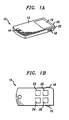
- Referring to FIG. 1A, there is shown one preferred embodiment of an integrated circuit package for the present invention memory chip, hereinafter referred to as a
music chip 10. Themusic chip 10 is essentially a memory component which is adapted to be received into an accompanying solid state audio player for playing music contained in memory. The physical characteristics of thechip 10 are essentially that of a flat rectangular device having dimensions of approximately 2.5" x 1.125" x 0.25" and housed in a rugged ABS plastic (acrylic butyl styrene) or other like material. The relatively modest sized music chip device will have significant advantages over compact discs and other media with regard to transportability and storage. Memory and interface circuitry of thechip 10 are embedded within the package, as will be explained. - The
music chip 10, as will be understood is intended for the storage of pre-recorded audio, namely, music. Agraphics window 12 is included on atop surface 14 of the chip for display of artwork and other indicia associated with pre-recorded music sold in retail markets. Thus, thegraphics window 12 will contain information similar in scope to that found on the front of a compact disc or cassette tape package. A front portion of thechip 10, at an opposite end from thegraphics window 12 includes acylindrical hollow 16 extending completely through the flat body portion of the chip. The hollow 16 presents a convenient manner for carrying one or more of the chips, in that the devices may be strung through the hollow and retained on a key chain or in another similar manner. On either side of thechip 10, proximate thegraphics window 12,metal contacts degree notch 20 is located in the top right hand comer of thechip 10 in order to conveniently designate theback end 22 of the chip as an area which should be first inserted into the audio player. Thenotch 20 also distinguishes face-up versus face-down insertion of thechip 10. - Referring to FIG. 1B, an underside view of the
chip 10 is depicted. A set of four capacitive plates 23-26 are embedded in the underside 28 of the chip for transfer of data between the chip and player. Utilizing the embedded capacitive plates 23-26 in conjunction with the rugged plastic housing material makes the device extremely tolerant to most any type of handling. In addition, because of the unique packaging and associated circuit design, many problems common to other types of integrated circuits, such as electro-static discharge (ESD), are greatly minimized. - The memory of the
music chip 10, as has been explained, will contain prerecorded music or other like audio content, wherein the music is stored in a compressed digital format. Compression is performed according to an audio coding algorithm, a detailed discussion of which is not required for understanding of the present invention. - Referring to FIG. 2, there is shown one preferred representation for the internal circuit configuration of the present
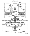
invention music chip 10. As has been mentioned, the music chip, 10 is adapted to be received into a solid state audio player. FIG. 2 depicts themusic chip 10 as it is coupled to such anaudio player 30. It will be understood that theaudio player 30 will be any one of a number of devices, for example portable or stationary, which devices are adapted to access, receive and play digital audio stored in memory of amusic chip 10. As shown, theaudio player 30 includes a digital signal processor (DSP) 32 for decoding the digitally stored data in memory of the music chip. Adata line 34 is coupled from theDSP 32 to adata shift register 36 on theplayer 30. Anaddress line 38 and bit I/O line 40 are similarly coupled from the DSP to anaddress shift register 42. The address, bit I/O and data lines send and receive data to and from theshift registers music chip 10. It will be understood that the address, bit I/O and data lines may be in bus format to accommodate parallel data transfer. In this case, the shift registers 36, 42 would necessarily be adapted to receive the parallel data and then output same in serial form, or in the alternative, receive serial data and be able to output the data in parallel. In either case, data is then transferred serially to and from the shift registers 36, 42 of theaudio player 30 via matching capacitive plates 43-46 which correspond to the capacitive plates 23-46 of themusic chip 10. The corresponding plates come into alignment when themusic chip 10 is inserted within theaudio player 30 creating a plurality of capacitors which form a capacitively coupled interface. - Referring again to FIG. 2, it can be seen that the structure of
internal memory 50 themusic chip 10 appears similar in nature to that, for example, of a flash EEPROM. An array ofmemory cells 50 is included therein, wherein eachmemory cell 50 is individually addressable via aparallel address bus 52. Eachmemory cell 50 is read from (or written to, if applicable) over aparallel data bus 54. The memory for the music chip will typically be Read Only Memory (ROM), wherein the pre-recorded digital audio will be represented in a mask which is copied at time of fabrication and which will exactly replicate the audio of a master encoding from which it was reproduced. - As an alternative, the memory of the music chip can also be a type of programmable ROM (PROM), wherein each of the memory cells is written to a single time in order to store blocks of audio. As another alternative, the memory could also be a nonvolatile Random Access Memory (RAM) device, for example, FLASH RAM, wherein both read and write operations may be accomplished. In the case of pre-recorded audio, however, write operations to the music chip will never normally be necessary once the audio has been recorded, thus, the additional production costs associated with RAMs would not appear justified.
- Within the shown embodiment of the
music chip 10 in FIG. 2, aparallel address bus 52 anddata bus 54 are coupled to each of thememory cells 50. It will be understood, of course, that the address bus may be coupled to the memory throughdecoder circuitry 51, which is known in the art. As shown, theaddress bus 52 and thedata bus 54 are uni-directional buses with the designatedarrows 53 being representative of the direction of data flow. That is, addresses from the audio player are accepted into the music chip to access specific memory locations, while data from the memory cells, after being accessed, is then output over thedata bus 54. It will be understood, however, that the data bus, in particular, may be made to be bidirectional depending on the memory technology employed within the chip. - As can be seen in FIG. 2, the
address bus 52 is coupled to anaddress buffer 56 and in a similar fashion thedata bus 54 is coupled to adata buffer 58. Theaddress buffer 56 anddata buffer 58 are in turn coupled to an associatedaddress shift register 60 anddata shift register 62, respectively, in themusic chip 10. The function of theaddress buffer 56 is to receive from theaddress shift register 60, wherein the address data can be accessed in parallel form, and output these addresses over theparallel address bus 52. In reverse fashion thedata buffer 56 receives parallel data from thedata bus 54 and temporarily buffers the data for parallel loading into thedata shift register 62. Addresses and data are transferred serially to and from the shift registers 60, 62 of the music chip by means of the capacitive plates 23-26 which are aligned with the capacitive plates 43-46 of theaudio player 30. - The transfer of addressing information and data to and from the
chip 10 to theaudio player 30 by means of capacitive plates 23-26 provides a significant advantage over other memory chip packages since the need for exposed electrical contacts is avoided. Conductive plates or electrodes having outer dielectric surfaces on both thechip 10 and theaudio player 30 form an electrical interface when each plate in the chip is aligned in close proximity with a corresponding plate in the player. When thechip 10 is in place within the audio player, addressing information and data are then reliably transferred. This remains true even after some time of use, since as for the data transfer circuitry, there are no exposed metal surfaces to corrode or to which particles may collect. In addition, the potential of damage from electrostatic discharge to electronics within the chip is minimized since an insulator in the form of a dielectric is provided between the conductors of the chip and any sources from which the discharge might occur. It will be understood that other types of interfaces may also be utilized, for example metallic contacts, however, the capacitive interface is preferred for the reasons discussed. - Referring to FIG. 3, there is shown a more detailed illustration of the capacitive interface found within the
music chip 10 andaudio player 30.Capacitive plates differential amplifier 70 adapted to receive data from correspondingcapacitive plates capacitive plates differential drive circuits 80 on theplayer 30. The output of thedifferential amplifier 70 is coupled to the input of theshift register 60 which receives the serial addressing information as explained with reference to FIG. 2. A data output drive circuit, comprisingdriver amplifiers data shift register 62 and receives serial data therefrom to differentially drive thecapacitive plates capacitive plates plates 45, 46 in the player when the chip is inserted, wherein data is received at adifferential amplifier 81 and received atshift register 36. Thedriver amplifiers data shift register 62 of the music chip which is of one polarity, into a differential polarity such that for each transition of a signal from the chip, one of the drivers goes positive, while the other goes negative. Thus, two of the capacitive plates on the chip are utilized for data (or addressing) input, while two plates are used for data output. As can be seen, a mirror image of the same scheme is used for theplayer 30. The differential data transfer scheme ensures a more reliable transfer of information since two data terminals are active to indicate a transition from one state to another. Moreover, hysterisis is built into the data receive circuits to prevent false triggering from outside noise. - As has been explained,
metallic contacts chip 10 to provide power, ground and clock signals to the internal circuitry thereof. Althoughmetal contacts - In a preferred embodiment of the invention, only two contacts are used to provide power (3.3 VDC), ground and clock signals, wherein the clock signal is transmitted in conjunction with one of the power connections. This is done to reduce susceptibility to ESD by minimizing the exposed contact area, as well as to minimize the effects of corrosion on exposed metal surfaces. Referring to FIG. 4, there are shown preferred embodiments of a dc offset
circuit 90 andclock recovery circuit 92 used in theaudio player 30 andmusic chip 10, respectively, to transmit the power and clock signals together from one contact. The dc offsetcircuit 90 includes transistor T1 (MOSFET) which is biased by means of resistive divider network comprised of resistors R1 and R2 and functions to provide a stable dc offset for the voltage output VDD of theaudio player 30 . The offset signal from the transistor T1 enters a diode-resistive network 91 which prevents bleed-back of the clock signal (OSC) into the power circuit. Diode D1 is forward biased to pass the offset signal. R3 is assigned a relatively large value, for example, one mega-ohm, so as to be able to pass only minimal feedback current. The clock signal (OSC) is added or mixed with the dc offset signal at junction J1 where the clock signal effectively rides on the dc carrier, as shown. Besides providing a stable offset value, the dc offset circuit of FIG. 4 also creates a buffer between the power circuitry and the exposed contact. The values of R1 and R2 are chosen according to the desired offset, wherein typically, R1 is selected to be much greater than R2. - The combination signal is transferred from the
audio player 30 to the music chip through one of themetal contacts recovery circuit 92. The VDC recovery circuit is comprised of alow pass filter 94 including R11, C11, R11 and C11 integrate the input signal over time to produce a dc signal, wherein VDC appears at theoutput terminal 95 of thelow pass filter 94. The clock recovery circuit 96 includes amplifying transistor T2 which is driven into enhancement or depletion mode by the ac clock signal. Capacitor C21 blocks the dc portion of the combination signal and the extracted clock signal appears at anoutput terminal 97 which is coupled to the drain of transistor T2. Depending on the clock frequency utilized, R11, C11 and RD, RS are chosen so that RD is much greater than RS. It will be understood that in the alternative, three contacts may be provided for the transfer of each of the signals individually. As is known in the art, data transfer is coordinated throughout themusic chip 10 and audio player by means of the clock and other corresponding signals which are issued from the DSP. - In operation the present
invention music chip 10 functions as follows. An address request is issued from theDSP 32 of theaudio player 30 to read the contents of the data in a specific memory location of the music chip. Addressing information is transferred to theaddress shift register 42 of the audio player wherein it is transferred over the capacitive interface plates of the audio player and the chip, respectively. The address is received at the data receive circuit of themusic chip 10 where it is converted to a standard serial data string and then stored in theaddress shift register 60. In accordance with the clock cycles and control signals of theDSP 32, the address information from theaddress shift register 60 is gated into theaddress buffer 56 where the information is placed on theparallel address bus 54 to access a specific memory location. Once the specific memory cell has been identified, data is read from the memory cell and placed on theparallel data bus 54. The data is transferred over thedata bus 54 and received in parallel at thedata buffer 58 . Data from thedata buffer 58 is then loaded into thedata shift register 62 in parallel form. The data loaded in thedata shift register 62 can then be serially output through the driver circuitry over the capacitive interface where it is received at thedata shift register 36 of theaudio player 30. The data is then ready to be processed by means of theDSP 32. In a preferred embodiment of the invention, data transfer to and from the memory will take place at a 150 Khz rate. - A unique architecture for digitally storing audio within a semiconductor chip has thus been presented. The chip allows for serial transfer of data to and from the chip by means of a capacitively coupled interface to the audio player. Serial data is then converted and transferred within the chip by means of parallel address and data buses. Data is then once again output in a serial fashion for decoding and processing by the audio player.
- From the above, it should be understood that the embodiments described, in regard to the drawings, are merely exemplary and that a person skilled in the art may make variations and modifications to the shown embodiments without departing from the scope of the invention. All such variations and modifications are intended to be included within the scope of the invention as defined in the appended claims.
Claims (6)
- A semiconductor chip memory apparatus (10) for storage of pre-recorded audio, said memory apparatus being adapted for use with a solid state audio player (30), said apparatus including:a plurality of memory cells (50) for storing digital data therein;an address shift register (60) for inputting from the audio player serial data corresponding to addresses of memory locations and outputting the serial data in parallel form to the memory cells; anda data shift register (62) for receiving parallel data from said memory cells and outputting to the audio player the received data in serial form.
- Apparatus as claimed in claim 1, wherein said plurality of memory cells include Read Only Memory (ROM).
- Apparatus as claimed in claim 1, wherein said plurality of memory cells include a type of programmable Read Only Memory.
- Apparatus as claimed in claim 1, further including means for decoding said input data received from said audio player to thereby access specific ones of said memory cells.
- Apparatus as claimed in claim 1, including a parallel address bus (52) and parallel data bus (54), wherein said address shift register is adapted to output parallel address data on said address bus and said data shift register is adapted to receive parallel input data from said data bus.
- Apparatus as claimed in claim 5, including an address buffer (56) and a data buffer (58), wherein said address buffer is operative to receive address information from said address shift register for placement on said address bus and said data buffer is operative to receive data from said data bus for input to said data shift register.
Applications Claiming Priority (2)
| Application Number | Priority Date | Filing Date | Title |
|---|---|---|---|
| US447335 | 1989-12-07 | ||
| US08/447,335 US5696928A (en) | 1995-05-22 | 1995-05-22 | Memory chip architecture for digital storage of prerecorded audio data wherein each of the memory cells are individually addressable |
Publications (3)
| Publication Number | Publication Date |
|---|---|
| EP0744752A2 EP0744752A2 (en) | 1996-11-27 |
| EP0744752A3 EP0744752A3 (en) | 1998-05-20 |
| EP0744752B1 true EP0744752B1 (en) | 2002-06-26 |
Family
ID=23775956
Family Applications (1)
| Application Number | Title | Priority Date | Filing Date |
|---|---|---|---|
| EP96303619A Expired - Lifetime EP0744752B1 (en) | 1995-05-22 | 1996-05-21 | Memory chip architecture |
Country Status (7)
| Country | Link |
|---|---|
| US (1) | US5696928A (en) |
| EP (1) | EP0744752B1 (en) |
| JP (2) | JP3886561B2 (en) |
| KR (1) | KR100247671B1 (en) |
| CA (1) | CA2176988C (en) |
| DE (1) | DE69621985T2 (en) |
| TW (1) | TW299449B (en) |
Families Citing this family (24)
| Publication number | Priority date | Publication date | Assignee | Title |
|---|---|---|---|---|
| US6199076B1 (en) * | 1996-10-02 | 2001-03-06 | James Logan | Audio program player including a dynamic program selection controller |
| JPH10187199A (en) * | 1996-12-24 | 1998-07-14 | Oki Electric Ind Co Ltd | Semiconductor storage medium recording device and semiconductor storage medium reproducing device |
| WO1998045787A1 (en) * | 1997-04-10 | 1998-10-15 | Advanced Micro Devices, Inc. | Pin count reduction through serialization techniques |
| GB2325547B (en) * | 1997-05-23 | 2000-04-19 | Texas Instruments Ltd | Improvements in or relating to data communications |
| US6442178B1 (en) * | 1997-10-01 | 2002-08-27 | Globespanvirata Inc. | System and method for data alignment in a communication system |
| KR100287366B1 (en) | 1997-11-24 | 2001-04-16 | 윤순조 | Portable device for reproducing sound by mpeg and method thereof |
| US6425018B1 (en) | 1998-02-27 | 2002-07-23 | Israel Kaganas | Portable music player |
| US6067278A (en) * | 1998-04-06 | 2000-05-23 | Recoton Corporation | Digital recorder for car radio |
| DE60003549T2 (en) | 1999-04-30 | 2004-04-29 | Thomson Licensing S.A., Boulogne | METHOD AND DEVICE FOR PROCESSING DIGITALLY CODED AUDIO DATA |
| US6824063B1 (en) | 2000-08-04 | 2004-11-30 | Sandisk Corporation | Use of small electronic circuit cards with different interfaces in an electronic system |
| US6820148B1 (en) | 2000-08-17 | 2004-11-16 | Sandisk Corporation | Multiple removable non-volatile memory cards serially communicating with a host |
| JP3687090B2 (en) * | 2000-12-19 | 2005-08-24 | ヤマハ株式会社 | Storage device with sound source |
| DE10142675A1 (en) * | 2001-08-31 | 2003-04-03 | Infineon Technologies Ag | control register |
| TWI242156B (en) | 2001-11-09 | 2005-10-21 | Via Tech Inc | Recording method for improving interrupted interference |
| US7162628B2 (en) * | 2002-07-23 | 2007-01-09 | Cisco Technology, Inc. | Method, system, apparatus and program product for temporary personalization of a computer terminal |
| US7246199B2 (en) * | 2003-05-29 | 2007-07-17 | Elantec Semiconductor, Inc. | Double buffering of serial transfers |
| US8205072B1 (en) | 2003-07-22 | 2012-06-19 | Cisco Technology, Inc. | Method and apparatus for electronically configuring a secured user desktop |
| US20050223182A1 (en) * | 2004-04-04 | 2005-10-06 | Guobiao Zhang | User-configurable pre-recorded memory |
| TWI245191B (en) * | 2004-09-14 | 2005-12-11 | Ali Corp | Sound receiving and pre-recording device and method |
| TWI346926B (en) * | 2006-08-29 | 2011-08-11 | Au Optronics Corp | Esd protection control circuit and lcd |
| US20090259772A1 (en) * | 2008-04-11 | 2009-10-15 | Nokia Corporation | Apparatus for a user removable memory or a device for communication with a user removable memory, and associated methods |
| US8659835B2 (en) * | 2009-03-13 | 2014-02-25 | Optotune Ag | Lens systems and method |
| FR2985032B1 (en) * | 2011-12-23 | 2014-01-17 | Chauvin Arnoux | GROUND CLAMP FOR MEASURING THE EARTH RESISTANCE OF ELECTRICAL INSTALLATIONS |
| US20170199719A1 (en) * | 2016-01-08 | 2017-07-13 | KIDdesigns Inc. | Systems and methods for recording and playing audio |
Family Cites Families (12)
| Publication number | Priority date | Publication date | Assignee | Title |
|---|---|---|---|---|
| US4044339A (en) * | 1975-12-15 | 1977-08-23 | Honeywell Inc. | Block oriented random access memory |
| US4148099A (en) * | 1978-04-11 | 1979-04-03 | Ncr Corporation | Memory device having a minimum number of pins |
| JPS6298437A (en) * | 1985-10-24 | 1987-05-07 | Oki Electric Ind Co Ltd | Microcomputer |
| US4813014A (en) * | 1986-04-14 | 1989-03-14 | Phi Technologies, Inc. | Digital audio memory system |
| US4798322A (en) * | 1986-04-28 | 1989-01-17 | American Telephone And Telegraph Company | Card reader/writer station for use with a personal memory card using differential data transfer |
| US4795898A (en) * | 1986-04-28 | 1989-01-03 | American Telephone And Telegraph Company | Personal memory card having a contactless interface using differential data transfer |
| EP0245531A1 (en) * | 1986-05-14 | 1987-11-19 | Deutsche ITT Industries GmbH | Application of a semiconductor read only memory |
| JP2923786B2 (en) * | 1988-03-18 | 1999-07-26 | 日立マクセル株式会社 | Semiconductor file memory and storage system using the same |
| US5199033A (en) * | 1990-05-10 | 1993-03-30 | Quantum Corporation | Solid state memory array using address block bit substitution to compensate for non-functional storage cells |
| US5119172A (en) * | 1991-03-04 | 1992-06-02 | Motorola, Inc. | Microelectronic device package employing capacitively coupled connections |
| DE4229710B4 (en) * | 1991-09-09 | 2008-06-05 | Samsung Electronics Co., Ltd. | Digital audio data storage system and digital audio system equipped therewith |
| US5444767A (en) * | 1994-03-09 | 1995-08-22 | Gregory J. Goetcheus | Systems and methods for recording and delivering personalized audio messages |
-
1995
- 1995-05-22 US US08/447,335 patent/US5696928A/en not_active Expired - Lifetime
-
1996
- 1996-05-21 CA CA002176988A patent/CA2176988C/en not_active Expired - Fee Related
- 1996-05-21 DE DE69621985T patent/DE69621985T2/en not_active Expired - Lifetime
- 1996-05-21 EP EP96303619A patent/EP0744752B1/en not_active Expired - Lifetime
- 1996-05-22 KR KR1019960017312A patent/KR100247671B1/en not_active IP Right Cessation
- 1996-05-22 JP JP12678796A patent/JP3886561B2/en not_active Expired - Lifetime
- 1996-07-06 TW TW085108195A patent/TW299449B/zh not_active IP Right Cessation
-
2006
- 2006-08-11 JP JP2006219279A patent/JP4278062B2/en not_active Expired - Lifetime
Also Published As
| Publication number | Publication date |
|---|---|
| JPH0917175A (en) | 1997-01-17 |
| JP4278062B2 (en) | 2009-06-10 |
| TW299449B (en) | 1997-03-01 |
| DE69621985T2 (en) | 2003-02-20 |
| JP3886561B2 (en) | 2007-02-28 |
| CA2176988A1 (en) | 1996-11-23 |
| EP0744752A3 (en) | 1998-05-20 |
| CA2176988C (en) | 2000-04-04 |
| EP0744752A2 (en) | 1996-11-27 |
| US5696928A (en) | 1997-12-09 |
| KR100247671B1 (en) | 2000-03-15 |
| JP2007012084A (en) | 2007-01-18 |
| DE69621985D1 (en) | 2002-08-01 |
| MX9601918A (en) | 1997-09-30 |
Similar Documents
| Publication | Publication Date | Title |
|---|---|---|
| EP0744752B1 (en) | Memory chip architecture | |
| JP5198711B2 (en) | Use of small electronic circuit cards at various interfaces in electronic systems. | |
| US20050079738A1 (en) | USB storage device including USB plug with top and bottom terminals | |
| US20020134837A1 (en) | Method and apparatus for electronically exchanging data | |
| MX9806203A (en) | Capacitive data card and reader thereof. | |
| KR950009602A (en) | Recording and reproducing apparatus having a recording medium cassette and a recording medium cassette | |
| US6189055B1 (en) | Multi-module adapter having a plurality of recesses for receiving a plurality of insertable memory modules | |
| US6725291B2 (en) | Detection method used in adaptor capable of inserting various kinds of memory cards | |
| EP0744750B1 (en) | Capacitive interface for coupling between a music chip and audio player | |
| US5724482A (en) | Smart tray for audio player | |
| US6687168B2 (en) | Method for writing data bits to a memory array | |
| MXPA96001918A (en) | Memo chip architecture | |
| WO2002084705A3 (en) | Method for operating an mram semiconductor memory arrangement | |
| KR100374816B1 (en) | Detection apparatus for the data store medium of digital data player | |
| EP0710955A3 (en) | Data storage apparatus | |
| JPS6134790A (en) | Semiconductor memory device | |
| JPS61211779A (en) | Solid memory | |
| US6470411B2 (en) | Method and device for accessing sets of data contained in mass memory | |
| JPH01234297A (en) | Card holder | |
| JPS6072049A (en) | Single inline memory module | |
| MXPA96001910A (en) | Capacitive interconnection for coupling between chip of music and an au player | |
| JPH0492297A (en) | Recording and reproducing device | |
| WO1998031008A2 (en) | Smart voice card system | |
| JPH05101660A (en) | Dynamic semiconductor memory device | |
| JPS59108333U (en) | variable resistor |
Legal Events
| Date | Code | Title | Description |
|---|---|---|---|
| PUAI | Public reference made under article 153(3) epc to a published international application that has entered the european phase |
Free format text: ORIGINAL CODE: 0009012 |
|
| AK | Designated contracting states |
Kind code of ref document: A2 Designated state(s): DE ES FR GB IT |
|
| PUAL | Search report despatched |
Free format text: ORIGINAL CODE: 0009013 |
|
| AK | Designated contracting states |
Kind code of ref document: A3 Designated state(s): DE ES FR GB IT |
|
| 17P | Request for examination filed |
Effective date: 19981106 |
|
| 17Q | First examination report despatched |
Effective date: 20000120 |
|
| GRAG | Despatch of communication of intention to grant |
Free format text: ORIGINAL CODE: EPIDOS AGRA |
|
| GRAG | Despatch of communication of intention to grant |
Free format text: ORIGINAL CODE: EPIDOS AGRA |
|
| GRAH | Despatch of communication of intention to grant a patent |
Free format text: ORIGINAL CODE: EPIDOS IGRA |
|
| GRAH | Despatch of communication of intention to grant a patent |
Free format text: ORIGINAL CODE: EPIDOS IGRA |
|
| GRAA | (expected) grant |
Free format text: ORIGINAL CODE: 0009210 |
|
| AK | Designated contracting states |
Kind code of ref document: B1 Designated state(s): DE ES FR GB IT |
|
| PG25 | Lapsed in a contracting state [announced via postgrant information from national office to epo] |
Ref country code: IT Free format text: LAPSE BECAUSE OF FAILURE TO SUBMIT A TRANSLATION OF THE DESCRIPTION OR TO PAY THE FEE WITHIN THE PRESCRIBED TIME-LIMIT;WARNING: LAPSES OF ITALIAN PATENTS WITH EFFECTIVE DATE BEFORE 2007 MAY HAVE OCCURRED AT ANY TIME BEFORE 2007. THE CORRECT EFFECTIVE DATE MAY BE DIFFERENT FROM THE ONE RECORDED. Effective date: 20020626 |
|
| REG | Reference to a national code |
Ref country code: GB Ref legal event code: FG4D |
|
| REF | Corresponds to: |
Ref document number: 69621985 Country of ref document: DE Date of ref document: 20020801 |
|
| ET | Fr: translation filed | ||
| PG25 | Lapsed in a contracting state [announced via postgrant information from national office to epo] |
Ref country code: ES Free format text: LAPSE BECAUSE OF FAILURE TO SUBMIT A TRANSLATION OF THE DESCRIPTION OR TO PAY THE FEE WITHIN THE PRESCRIBED TIME-LIMIT Effective date: 20021220 |
|
| PLBE | No opposition filed within time limit |
Free format text: ORIGINAL CODE: 0009261 |
|
| STAA | Information on the status of an ep patent application or granted ep patent |
Free format text: STATUS: NO OPPOSITION FILED WITHIN TIME LIMIT |
|
| 26N | No opposition filed |
Effective date: 20030327 |
|
| REG | Reference to a national code |
Ref country code: DE Ref legal event code: R082 Ref document number: 69621985 Country of ref document: DE Representative=s name: DILG HAEUSLER SCHINDELMANN PATENTANWALTSGESELL, DE |
|
| REG | Reference to a national code |
Ref country code: FR Ref legal event code: PLFP Year of fee payment: 20 |
|
| PGFP | Annual fee paid to national office [announced via postgrant information from national office to epo] |
Ref country code: GB Payment date: 20150424 Year of fee payment: 20 Ref country code: DE Payment date: 20150422 Year of fee payment: 20 |
|
| PGFP | Annual fee paid to national office [announced via postgrant information from national office to epo] |
Ref country code: FR Payment date: 20150422 Year of fee payment: 20 |
|
| REG | Reference to a national code |
Ref country code: DE Ref legal event code: R071 Ref document number: 69621985 Country of ref document: DE |
|
| REG | Reference to a national code |
Ref country code: GB Ref legal event code: PE20 Expiry date: 20160520 |
|
| PG25 | Lapsed in a contracting state [announced via postgrant information from national office to epo] |
Ref country code: GB Free format text: LAPSE BECAUSE OF EXPIRATION OF PROTECTION Effective date: 20160520 |