EP0744706A2 - Apparatus and method for colour inket printing - Google Patents
Apparatus and method for colour inket printing Download PDFInfo
- Publication number
- EP0744706A2 EP0744706A2 EP96302983A EP96302983A EP0744706A2 EP 0744706 A2 EP0744706 A2 EP 0744706A2 EP 96302983 A EP96302983 A EP 96302983A EP 96302983 A EP96302983 A EP 96302983A EP 0744706 A2 EP0744706 A2 EP 0744706A2
- Authority
- EP
- European Patent Office
- Prior art keywords
- horizontal scanning
- dots
- dot formation
- dot
- Prior art date
- Legal status (The legal status is an assumption and is not a legal conclusion. Google has not performed a legal analysis and makes no representation as to the accuracy of the status listed.)
- Granted
Links
- 238000000034 method Methods 0.000 title claims description 26
- 238000003491 array Methods 0.000 claims abstract description 21
- 239000011295 pitch Substances 0.000 claims description 89
- 230000015572 biosynthetic process Effects 0.000 claims description 75
- 239000003086 colorant Substances 0.000 claims description 26
- 239000011159 matrix material Substances 0.000 claims description 10
- 230000004044 response Effects 0.000 claims description 6
- 239000000976 ink Substances 0.000 description 51
- 230000000740 bleeding effect Effects 0.000 description 9
- 230000003204 osmotic effect Effects 0.000 description 6
- 230000008569 process Effects 0.000 description 6
- 238000012545 processing Methods 0.000 description 5
- 230000002708 enhancing effect Effects 0.000 description 4
- 230000008859 change Effects 0.000 description 3
- 230000000593 degrading effect Effects 0.000 description 3
- 230000000694 effects Effects 0.000 description 3
- 230000006872 improvement Effects 0.000 description 3
- 230000015556 catabolic process Effects 0.000 description 2
- 238000012937 correction Methods 0.000 description 2
- 238000006731 degradation reaction Methods 0.000 description 2
- 230000006978 adaptation Effects 0.000 description 1
- 238000006243 chemical reaction Methods 0.000 description 1
- 230000006870 function Effects 0.000 description 1
- 238000012986 modification Methods 0.000 description 1
- 230000004048 modification Effects 0.000 description 1
- 230000002265 prevention Effects 0.000 description 1
- 230000009467 reduction Effects 0.000 description 1
- 238000011946 reduction process Methods 0.000 description 1
Images


Classifications
-
- G—PHYSICS
- G06—COMPUTING; CALCULATING OR COUNTING
- G06K—GRAPHICAL DATA READING; PRESENTATION OF DATA; RECORD CARRIERS; HANDLING RECORD CARRIERS
- G06K15/00—Arrangements for producing a permanent visual presentation of the output data, e.g. computer output printers
- G06K15/02—Arrangements for producing a permanent visual presentation of the output data, e.g. computer output printers using printers
- G06K15/10—Arrangements for producing a permanent visual presentation of the output data, e.g. computer output printers using printers by matrix printers
- G06K15/102—Arrangements for producing a permanent visual presentation of the output data, e.g. computer output printers using printers by matrix printers using ink jet print heads
- G06K15/105—Multipass or interlaced printing
Definitions
- This invention relates to serial scanning and drum scanning printers for printing while a print head is scanning the print media surface and in particular, to system improvements in head drive and scan intended for print image enhancement and throughput improvement.
- an invention called an "interlace system” is disclosed in USP No. 4198642, Japanese Patent Publication No. Sho. 53-2040, etc., as one of techniques for image enhancement in printers of the aforementioned type, particularly in ink jet printers.
- This interlace system features the ink jet nozzle array structure on a print head and the vertical scanning method. That is, the nozzle array consists of N nozzles arranged in the vertical scanning direction, the centre point spacing of contiguous nozzles (nozzle pitch) is set to k times pixel pitch D of a print image, and N and k are selected as integers having prime relation therebetween. The distance of vertical scanning executed after each horizontal scanning is set to N.D.
- the interlace system produces the effect of enhancing the print quality by dispersing variations in nozzle pitches, ink spout characteristics, etc., on a print image.
- Another technique intended for image quality improvement in colour ink jet printers is an art called "shingling" or "multiscan” disclosed in Japanese Patent Publication No. Hei. 3-207665, Japanese Patent Publication No. Hei. 4-19030, etc.
- the shingling uses a print head comprising a plurality of nozzle arrays for jetting ink of different colours arranged in parallel in the horizontal scanning direction.
- the shingling drives all the nozzle arrays of different colours at intermittent timing in one horizontal scanning for forming dots every given number of dots in the horizontal scanning direction and forming dots of all colours at different positions by each nozzle array in one horizontal direction.
- Such horizontal scanning is repeated more than once by shifting the nozzle drive timing at each time, thereby completing formation of all dots on the line continuous in the horizontal scanning direction.
- ink dots of different colours are not formed overlapping at the same position in a single horizontal scanning, thus solving a so-called ink bleeding problem in which ink dots of different colours are integrated with each other, so degrading the image quality.
- the first problem lies in that throughput lowers. That is, to reliably prevent ink bleeding, it is desired to suppress formation of dots of different colours in a single horizontal scanning at not only the same dot positions, but also contiguous dot positions.
- throughput lowers. That is, to reliably prevent ink bleeding, it is desired to suppress formation of dots of different colours in a single horizontal scanning at not only the same dot positions, but also contiguous dot positions.
- printing at all dot positions must be completed by repeating horizontal scanning four times or more.
- a bi-directional print method for printing on both go and return ways of horizontal scanning is adopted, it is necessary to repeat a go and return twice or more; if the bi-directional printing is not adopted, a go and return must be repeated four times or more.
- the printing speed lowers, reducing throughput.
- the second problem lies in that scanning control becomes complicated.
- the drum scanning printer cannot be adopted. That is, the drum scanning printer adopts a scanning system for running a print head at a given speed while rotating a drum at a given speed, thereby providing high throughput and high image quality.
- This scanning system is the same as the system for simply executing horizontal scanning and vertical scanning alternately from the viewpoint of the relative relationship between the head and media.
- the drum scanning printer cannot execute bi-directional printing because of adaptation of the above-mentioned scanning system.
- the drum scanning printer cannot adopt the conventional shingling, because if an attempt is made to execute the shingling under conditions where bi-directional printing is impossible, it is inevitable to repeat horizontal scanning more than once between successive vertical scanning. This means that the system for simply repeating horizontal scanning and vertical scanning alternately cannot be adopted and that the scanning system of the drum scanning printer is not compatible with the shingling.
- this invention provides an apparatus in which a print head thereof executes a horizontal scanning and a vertical scanning on a surface of a print medium for printing the surface of the print medium, the apparatus comprising:
- this invention provides a method of printing on a surface of a print medium with a print head having a dot formation element array including N dot formation elements for forming dots of a single colour arranged at constant pitches in a vertical scanning direction, the method comprising the steps of:
- the apparatus and printing method according to the invention use a print head having a dot formation element array comprising N dot formation elements for forming dots of a single colour (for example, ink jet nozzles) arranged at constant pitches in a vertical scanning direction and executes horizontal scanning and vertical scanning of the print head alternately.
- the dot formation element array of the print head is driven for either or both of the go way and return way of the horizontal scanning for forming dots on a print medium.
- the vertical scanning is always executed by a predetermined distance.
- the distance of one vertical scanning is defined as a vertical scanning pitch L, the number of horizontal scanning repetitions required for printing a line continuous in a horizontal scanning direction as the number of scan repetitions s, a value representing a distance between centre points of the dot formation elements by a multiple of a dot pitch of a print image as an element pitch k, and the number of the dot formation elements existing per unit distance in the dot formation element array as an element density D.
- an arbitrary integer between more than one and less than N is selected as the number of scan repetitions s
- an arbitrary integer between more than one and less than N having prime relation with N/s is selected as the element pitch k, that is, the relation between N/s and k is such that k is not a factor of N/s and N/s is not a factor of k
- a value satisfying a relational expression of L N/(s ⁇ D ⁇ k) is selected as the vertical scanning pitch L.
- s is selected such that N/s is an integer.
- the dot formation element array is driven at intermittent timing during the horizontal scanning, dots spaced from each other in both horizontal and vertical scanning directions are formed by a single dot formation element, namely, contiguous dots are formed by different dot formation elements.
- variations in the dot formation characteristics of the nozzles, etc. are dispersed in both the horizontal and vertical scanning directions, enhancing the print image quality.
- One preferred form of driving at the intermittent timing is to drive the dot formation element array at the intermittent timing corresponding to dots at intervals of (s-1) dots.
- the preferred form is to drive the dot formation element array so that different dots in a dot matrix having s dots in the horizontal scanning direction and k dots in the vertical scanning direction are formed by repeating the horizontal scanning s x k successive times.
- the horizontal scanning direction distance between dots formed by a single dot formation element in terms of the number of dot pitches
- the image resolution and the vertical scanning direction distance in terms of the number of dot pitches
- the greater the number of scan repetitions s and the nozzle pitch k the more improved are the image resolution and quality.
- the user can select appropriate resolution and image quality according to the application.
- the throughput is degraded as the number of scan repetitions s and the nozzle pitch k increase. Then, if the horizontal scanning speed is increased as the number of scan repetitions s increases, a reduction in the throughput caused by the increase in the number of scan repetitions s can be suppressed.
- the number of repetitions s and the nozzle pitch k can be set as properly large values for preventing dots of different colours from being formed not only at the same position, but also at contiguous positions in the same horizontal scanning for colour printing, thereby extremely well preventing ink bleeding, enhancing the image quality all the more.
- the preferred embodiment of the invention comprises four dot formation element arrays for forming dots of four colours black, cyan, magenta, and yellow and drives the four dot formation element arrays at different timings so as to form dots of different colours at different dot positions during one horizontal scanning, whereby ink bleeding when colour printing is executed can be prevented.
- high throughput can be obtained as compared with the case where an attempt is made to bring about a similar bleed prevention effect by executing the conventional shingling.
- both the number of scan repetitions s and the nozzle pitch k are set to even numbers, whereby if bi-directional printing is executed, one line in the horizontal scanning direction is always printed only on either the go or return way of the horizontal scanning, so that degradation in the throughput in bi-directional printing is reduced.
- the invention can also be applied for representing one pixel by a plurality of dots to represent multiple tone images.
- one pixel is represented by a dot matrix consisting of s dots in the horizontal scanning direction x k dots in the vertical scanning direction and printing of one pixel can be completed by executing horizontal scanning s x k times.
- different dots in one pixel are formed by different dot formation elements, thus variations in the dot formation characteristics of the dot formation elements can be absorbed or dispersed, enhancing the image quality.
- Fig. 1 shows the machine configuration of main parts of a colour ink jet printer of serial scanning type according to one embodiment of the invention.
- print paper 1 is wound by a paper feed roller 3 driven by a step motor from a paper stacker 2 and is fed in the vertical scanning direction on the surface of a platen board 5.
- a carriage 7 is pulled by a pulling belt 11 driven by step motor 9 and is moved along guide rails 13 in the horizontal scanning direction perpendicular to the vertical scanning direction.
- a print head 15K having black (K) ink and a print head 15CMY having colour ink of three colours cyan (C), magenta (M), and yellow (Y) are mounted on the carriage 7.
- the print heads 15K and 15CMY are arranged in the horizontal scanning direction as a whole.
- the colour ink print head 15CMY may be separated into three separate print heads for each colour of ink.
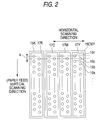
- Fig. 2 is a plan view showing arrays of ink jet nozzles placed on the surfaces of the print heads 15K and 15CMY facing the paper 1.
- the print head 15K is formed with a nozzle array 17K for jetting K ink and the print head 15CMY is formed with nozzle arrays 17C, 17M, and 17Y for jetting C ink, M ink and Y ink respectively.
- These four nozzle arrays 17K, 17C, 17M, and 17Y are completely matched with each other in vertical scanning direction positions and are placed in parallel in the horizontal scanning direction as a whole.
- Each of the nozzle arrays 17K, 17C, 17M, and 17Y comprises a large number of ink nozzles 19 1 , 19 2 , ... in a staggered arrangement with a given pitch k, which will be hereinafter called the nozzle pitch k, along the vertical scanning direction as a whole.
- a system for simply repeating horizontal scanning and vertical scanning alternately is adopted as a scanning system. That is, in unidirectional printing, while running back and forth once in the horizontal scanning direction, the print heads 15K and 15CMY are driven only on the go way for forming dots on the surface of the paper 1 and each time one running back and forth terminates, the paper 1 is fed by a given distance in the vertical scanning direction. In bi-directional printing, while running back and forth once in the horizontal scanning direction, the print heads 15K and 15CMY are driven on the both go and return ways for forming dots and each time one running on the go way or on the return way terminates, the paper 1 is fed by a given distance in the vertical scanning direction.
- L N/(s ⁇ D ⁇ k)
- N the total number of nozzles possessed by one nozzle array
- s the number of horizontal scanning repetitions required for completely printing one line continuous in the horizontal scanning direction, which will be hereinafter referred to as the number of scan repetitions
- k is the distance between the centre points of two contiguous nozzles in the vertical scanning direction, namely, the nozzle pitch.
- the nozzle pitch k is represented using a multiple of the dot pitch of a print image and is an arbitrarily selected integer between more than one and less than N such that k is not a factor of N/s and N/s is not a factor of k.
- D is a nozzle density, namely, the number of nozzles contained in one inch (2.54mm) of the nozzle array in the vertical scanning direction.
- s is selected such that N/s is an integer.
- the nozzle density D is represented by npi (nozzles per inch) units and therefore the vertical scanning pitch L is represented by inches (i).
- Table 1 lists the parameters in expression (1) as a specific example.
- N 30 [nozzles]
- D 180 [npi].
- Four print modes "high speed,” “standard,” “high quality,” and very high quality” are provided and proper values assigned to the parameters are set for each mode.
- the print mode "standard mode” is intended for printing in the most standard image quality and provides an image resolution (dot density on a print image) set to 360 dpi (dots per inch) as a standard value.
- the "high speed” mode is intended for printing at a higher speed than the standard mode and provides a resolution set to 180 dpi, a half of the resolution in the standard mode.
- the "high quality mode” is intended for printing in higher image quality than the standard mode and provides a resolution set to 720 dpi, twice that of the standard mode.
- the "very high quality mode” is intended for printing in furthermore higher image quality and provides a resolution set to 1440 dpi, four times that of the standard mode.
- the meanings of the parameters listed in Table 1 are as follows: The “number of scan repetitions s" and “nozzle pitch k” have already been explained.
- the “vertical scanning pitch L” also has already been explained; the numeric value of each denominator under the column listed in Table 1 denotes the image resolution and the numeric value of the numerator indicates that the vertical scanning pitch L is equivalent to what times the dot pitch (distance between contiguous dots).
- the "relative horizontal scanning speed” is the head running speed in each mode expressed in a relative ratio with the speed in the standard mode as 1.
- the "head frequency” is a clock signal frequency for driving each nozzle of the head.
- the "relative printing speed” is the number of pages that can be printed on paper of a given size within a given time (throughput), expressed in a relative ratio with that in the standard mode as 1.
- the "relative number of data pieces” is the amount of data that can be printed on paper of a given size (proportional to the square of the resolution), expressed in a relative ratio with that in the standard mode as 1.
- the most orthodox print operation is performed wherein the band area crossed by the nozzle arrays is completely printed by one horizontal scanning and upon completion of the horizontal scanning, vertical scanning is performed as wide as the band area. Therefore, special operation for image enhancement like interlace or shingling is not performed in the high speed mode.
- Fig. 3 shows schematically the positions of nozzles in the vertical scanning direction within one nozzle array and the positions of dots formed by the nozzles.
- the nozzle positions and dot positions denoted by the circled digits 1, 2, 3, ... indicate the positions of the nozzles in the vertical scanning direction and the positions of the dots formed by the nozzles in the first horizontal scanning, second horizontal scanning, third horizontal scanning, ...
- the nozzles 19 1 -19 30 are driven intermittently at 1-dot intervals for forming dots at every other dot position marked 1.
- the first horizontal scanning Upon completion of the first horizontal scanning, vertical scanning is performed only at the 15-dot distance, which is equivalent to the distance as long as seven nozzles plus one dot.
- the vertical scanning causes the nozzles 19 1 -19 30 to move to the positions marked 2, namely, the middle positions between the nozzle positions at the first horizontal scanning time.
- the second horizontal scanning is performed and the nozzles 19 1 -19 30 are driven intermittently at the same timing as the first horizontal scanning time, thereby forming new dots at the positions (2) downward contiguous in the figure to the dots at the first horizontal scanning time.
- the operation is executed with respect to one nozzle array.
- the four colour nozzle arrays 17K, 17C, 17M, and 17Y execute the operation at different drive timings from each other.
- the nozzle array 17K forms dots in the dot order of 1 to 2 to 3 to 4 in Fig. 3;
- the nozzle array 17C forms dots in the dot order of 2 to 3 to 4 to 1;
- the nozzle array 17M forms dots in the dot order of 3 to 4 to 1 to 2;
- the nozzle array 17Y forms dots in the dot order of 4 to 1 to 2 to 3.
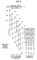
- Fig. 4 also shows schematically the positions of nozzles in the vertical scanning direction and the positions of dots formed by the nozzles, wherein some nozzles required for the description are extracted from one nozzle array, as in Fig. 3.
- the nozzle positions and dot positions denoted by the circled digits 1, 2, 3, ... indicate the positions of the nozzles in the vertical scanning direction and the positions of the dots formed by the nozzles in the first horizontal scanning, second horizontal scanning, third horizontal scanning, ...
- the nozzles 19 1 -19 30 are driven intermittently every other dot for forming dots at dot positions marked 1.
- vertical scanning is performed only at the 15-dot distance, which is equivalent to the distance as long as three nozzles plus three dots.
- the vertical scanning causes the nozzles 19 1 -19 30 to move to the positions marked 2, namely, the positions shifted one dot upward in the figure from the nozzle positions at the first horizontal scanning time.
- the second horizontal scanning is performed and the nozzles 19 1 -19 30 are driven at the same intermittent timing as the first horizontal scanning time, thereby forming new dots at the dot positions (2) upwardly contiguous to the dots at the first horizontal scanning time.
- 15-dot vertical scanning is performed, moving the nozzles 19 1 -19 30 to the positions shifted one dot upward from the nozzle positions in the third horizontal scanning, namely, the positions shifted one dot downward from the nozzle positions in the first horizontal scanning.
- the fourth horizontal scanning is performed and the nozzles 19 1 -19 30 are driven at the intermittent timing provided by inverting the phase from the drive timing at the third horizontal scanning time, thereby forming new dots at the dot positions (4) contiguous in the lower right slant direction in the figure to the dot positions in the first horizontal scanning.
- the subsequent vertical scanning causes the nozzles 19 1 -19 30 to move to the positions overlapping the positions at the first horizontal scanning time.
- the fifth horizontal scanning is performed and the nozzles 19 1 -19 30 are driven at the same timing as the fourth horizontal scanning time, thereby forming new dots at the dot positions (5) contiguous in the horizontal scanning direction to the dots in the first horizontal scanning.
- the nozzles 19 1 -19 30 are driven at the same timing as the fourth and fifth horizontal scanning times, thereby forming new dots at the dot positions (6) contiguous in the horizontal scanning direction to the dots in the second horizontal scanning. Then, although not shown in the figure, in the seventh horizontal scanning, new dots are formed at the dot positions contiguous in the horizontal scanning direction to the dots at the third horizontal scanning time, and in the eighth horizontal scanning, new dots are formed at the dot positions contiguous in the horizontal scanning direction to the dot positions at the fourth horizontal scanning time.
- the operation is executed with respect to one nozzle array.
- the four colour nozzle arrays 17K, 17C, 17M, and 17Y execute the operation at drive timings out of phase with each other. As a result, four-colour dots are formed at different positions and dots of different colours are not formed overlapping at the same positions in the same horizontal scanning.
- the mode uses only continuous 28 nozzles of 30 nozzles in each nozzle array.
- the relative horizontal scanning speed 4 means that the head runs at the speed four times that in the standard mode.
- the four colour nozzle arrays 17K, 17C, 17N, and 17Y operate at drive timings out of phase each other for forming four-colour dots at different positions in the same horizontal scanning.
- the number of scan repetitions s and the nozzle pitch k are set each to a value of 2 or more, whereby novel print operation into which the conventional interlace system and shingling are harmoniously integrated can be performed under the scanning system for simply repeating horizontal scanning and vertical scanning alternately.
- slow osmotic ink is used for K ink and very osmotic ink is used for CMY colour ink
- it is considered to adopt such a configuration that the print head 15CMY in Fig. 2 is shifted in the vertical scanning direction at the width of the half nozzle pitch ( k/2).
- dots in two types of ink can always be formed separately at diagonal positions in such a manner that K ink dots are formed at the dot positions marked 1 and colour ink dots are formed at the dot positions marked 4 in the first horizontal scanning, that K ink dots are formed at the dot positions marked 2 and colour ink dots are formed at the dot positions marked 3 in the second horizontal scanning, and that K ink dots are formed at the dot positions marked 3 and colour ink dots are formed at the dot positions marked 2 in the third horizontal scanning and so on.
- ink bleeding can be furthermore prevented because dots of two types are more spaced from each other as compared with the case where dots of two types are formed at contiguous positions in the horizontal or vertical scanning direction.
- the number of scan repetitions must be set to four or more and therefore the throughput becomes lower than that in the standard mode in the present invention.
- the throughput lowers less as the number of scan repetitions s and the resolution increase.
- unidirectional or bi-directional printing can be selected, as described above.
- the head In the unidirectional printing, the head is driven for forming dots only for the time when it runs on the go way.
- the bi-directional printing In the bi-directional printing, the head is driven for forming dots for the time when it runs on both the go and return ways. Therefore, the bi-directional printing provides throughput near twice that of the unidirectional printing; there is a possibility that dot formation positions will slightly shift between the go and return ways, degrading the image quality. This is caused by the fact that the ink jet speed from the ink jet head or the wire expanding speed from the wire impact head is finite.
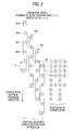
- Fig. 5 shows the configuration of a printer control circuit for performing the print operation.
- a printer driver of an external host computer 51 determines parameter values as listed in Table 1 based on the print mode specified by the user, generates print data appropriate for printing in the print mode based on the parameter values, and transfers the print data to the printer.
- the transferred data is once stored in a receive buffer memory 53.
- a system controller 55 reads the print data from the receive buffer memory 53 and sends a control signal to a horizontal scanning drive driver 57, a vertical scanning drive driver 61, and a head drive driver 69 based on the print data.
- a gate array 65 reads the print data from the receive buffer memory 53, generates K, C, N, and Y colour image data based on the print data, and writes the image data into a colour image buffer 67.
- the head drive driver 69 reads the colour image data from the image buffer 67 and drives colour nozzle arrays 17K, 17C, 17M, and 17Y in response to the control signal from the system controller 55.
- the horizontal scanning drive driver 57 and the vertical scanning drive driver 61 drive a carriage motor 59 and a paper feed motor 63 respectively in response to the control signals from the system controller 55.
- Fig. 6 shows a flow of the entire operation according to the configuration in Fig. 5.
- the printer driver in the host computer 51 processes image data in accordance with the print mode specified by the user at step S1 and transfers the print data of the processing result to the receive buffer memory 53 in the printer at step S2.
- the gate array 65 reads the print data from the receive buffer 53 at step S3, generates K, C, M, and Y colour image data for printing based on the print data, and writes the image data into the image buffer 67 at step S4.
- the carriage motor 59, the paper feed motor 63, and the colour nozzle arrays 17K, 17C, 17M, and 17Y are driven for printing under the control of the system controller 55 at step S5.
- the host computer 51 checks whether or not print mode change is input by the user at step S7 and if no change is input, terminates the above process and if change is input, again executes the process in a new print mode.
- Fig. 7 shows a flow of the image data processing (Fig. 6, S1) by the printer driver in the host computer 51.
- print mode selection is accepted from the user at step S1 and the parameter values of the number of scan repetitions s, the nozzle pitch k, etc., listed in Table 1 are determined in response to the selected print mode at step S12.
- scaling is performed, namely, the original image data generated by an application is converted into image data of the resolution corresponding to the selected print mode at step S13.
- an ink reduction process is executed, namely, a duty restriction is placed on the image data based on the ink acceptance amount limit on paper in response to the type of print paper selected by the user at step S14.
- colour correction and binarization process are performed on the image data (generally, 256 grey levels for each colour in RGB representation) for conversion to binary data in CMY representation at step S15.
- step S16 whether or not the resultant image data is optimum is checked. If the image data is not optimum, the processing is again performed starting at the print mode selection at step S11; if the image data is optimum, the image data is sorted so as to match the colour dot formation order corresponding to the print mode at step S17 and the image data processing is terminated.
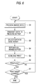
- Fig. 8 shows a flow of scanning and printing (Fig. 6, S5) performed under the control of the system controller 55.
- the print head and print paper are aligned so that printing can be started on the first print line at step S21.
- the colour image data is read from the image buffer 67 at step S22 and while the carriage is being run, the colour nozzles are driven for printing in response to the image data at step S23.
- the print paper is moved by vertical scanning pitch L at step S24. Steps S22 to S24 are repeated until printing of one page is complete.
- step S25 the scanning and printing process is terminated.
- the invention can also be embodied in various forms in addition to the embodiment.
- the invention can be applied not only to colour printing, but also to monochrome printing. It can also be applied to printing representing multiple tone images by representing one pixel by a plurality of dots. It can also be applied to drum scan printers. In the drum scan printer, the drum rotation direction is the vertical scanning direction and the carriage running direction is the horizontal scanning direction.
- This invention provides an apparatus in which a print head thereof executes a horizontal scanning and a vertical scanning on a surface of a print medium for printing the surface of the print medium, the apparatus comprising:
- This invention also provides a method of printing on a surface of a print medium with a print head having a dot formation element array including N dot formation elements for forming dots of a single colour arranged at constant pitches in a vertical scanning direction, the method comprising the steps of:
Abstract
Description
- This invention relates to serial scanning and drum scanning printers for printing while a print head is scanning the print media surface and in particular, to system improvements in head drive and scan intended for print image enhancement and throughput improvement.
- An invention called an "interlace system" is disclosed in USP No. 4198642, Japanese Patent Publication No. Sho. 53-2040, etc., as one of techniques for image enhancement in printers of the aforementioned type, particularly in ink jet printers. This interlace system features the ink jet nozzle array structure on a print head and the vertical scanning method. That is, the nozzle array consists of N nozzles arranged in the vertical scanning direction, the centre point spacing of contiguous nozzles (nozzle pitch) is set to k times pixel pitch D of a print image, and N and k are selected as integers having prime relation therebetween. The distance of vertical scanning executed after each horizontal scanning is set to N.D.
- The interlace system produces the effect of enhancing the print quality by dispersing variations in nozzle pitches, ink spout characteristics, etc., on a print image. Another technique intended for image quality improvement in colour ink jet printers is an art called "shingling" or "multiscan" disclosed in Japanese Patent Publication No. Hei. 3-207665, Japanese Patent Publication No. Hei. 4-19030, etc. The shingling uses a print head comprising a plurality of nozzle arrays for jetting ink of different colours arranged in parallel in the horizontal scanning direction. The shingling drives all the nozzle arrays of different colours at intermittent timing in one horizontal scanning for forming dots every given number of dots in the horizontal scanning direction and forming dots of all colours at different positions by each nozzle array in one horizontal direction. Such horizontal scanning is repeated more than once by shifting the nozzle drive timing at each time, thereby completing formation of all dots on the line continuous in the horizontal scanning direction.
- In the shingling, ink dots of different colours are not formed overlapping at the same position in a single horizontal scanning, thus solving a so-called ink bleeding problem in which ink dots of different colours are integrated with each other, so degrading the image quality.
- To provide high image quality in a colour printer, it is requisite to prevent degradation of the image quality by variations in nozzle pitches, spout characteristic, etc., and to prevent ink bleeding of dots of different colours. Hitherto, the interlace system has been known to meet the former requirement and the shingling has been known to meet the latter requirement.
- However, if the conventional interlace system and the conventional shingling are combined simply, the following problems occur:
- The first problem lies in that throughput lowers. That is, to reliably prevent ink bleeding, it is desired to suppress formation of dots of different colours in a single horizontal scanning at not only the same dot positions, but also contiguous dot positions. However, if an attempt is made to accomplish it by the conventional shingling, printing at all dot positions must be completed by repeating horizontal scanning four times or more. Thus, even if a bi-directional print method for printing on both go and return ways of horizontal scanning is adopted, it is necessary to repeat a go and return twice or more; if the bi-directional printing is not adopted, a go and return must be repeated four times or more. As a result, the printing speed lowers, reducing throughput.
- The second problem lies in that scanning control becomes complicated.
- That is, if a go and return of horizontal scanning is repeated twice or more to reliably prevent the ink bleeding as described above, vertical scanning is not executed during the go and return and upon completion of the repetitions, vertical scanning is executed. As a result, a simple scanning system for executing horizontal scanning and vertical scanning alternately cannot be adopted and scanning control becomes complicated. Such a scanning system can also cause band-like unevenness to occur on a print image.
- Further, the third problem lies in that a drum scanning printer cannot be adopted. That is, the drum scanning printer adopts a scanning system for running a print head at a given speed while rotating a drum at a given speed, thereby providing high throughput and high image quality. This scanning system is the same as the system for simply executing horizontal scanning and vertical scanning alternately from the viewpoint of the relative relationship between the head and media. The drum scanning printer cannot execute bi-directional printing because of adaptation of the above-mentioned scanning system.
- From these circumstances, the drum scanning printer cannot adopt the conventional shingling, because if an attempt is made to execute the shingling under conditions where bi-directional printing is impossible, it is inevitable to repeat horizontal scanning more than once between successive vertical scanning. This means that the system for simply repeating horizontal scanning and vertical scanning alternately cannot be adopted and that the scanning system of the drum scanning printer is not compatible with the shingling.
- It is therefore an object of the invention to provide a printer which can enhance a print image and improve throughput under a scanning system for simply executing horizontal scanning and vertical scanning alternately.
- In a first aspect, this invention provides an apparatus in which a print head thereof executes a horizontal scanning and a vertical scanning on a surface of a print medium for printing the surface of the print medium, the apparatus comprising:
- a dot formation element array having N dot formation elements for forming dots of a single colour, said dot formation elements being arranged on a surface of the print head and facing the print medium at constant pitches k in the vertical scanning direction;
- horizontal scanning drive means for executing the horizontal scanning of the print head;
- head drive means for driving said dot formation element array during the horizontal scanning; and
- vertical scanning drive means for executing the vertical scanning of the print head by a predetermined distance each time the horizontal scanning terminates;
- characterised in that the following conditions are satisfied;
- s is an integer between more than one and less than N,
- k is an integer between more than one and less than N, where k is not a factor of N/s and vice versa, and

- In a second aspect, this invention provides a method of printing on a surface of a print medium with a print head having a dot formation element array including N dot formation elements for forming dots of a single colour arranged at constant pitches in a vertical scanning direction, the method comprising the steps of:
- executing horizontal scanning of the print head;
- driving said dot formation element array during the horizontal scanning;
- executing vertical scanning of the print head by a predetermined distance each time the horizontal scanning terminates and characterised by further comprising the steps of:
- selecting s which is an integer between more than one and less than N;
- selecting k which is an integer between more than one and less than N such that K is not a factor of N/s and vice versa; and
- selecting L which satisfies the following equation,

- The apparatus and printing method according to the invention use a print head having a dot formation element array comprising N dot formation elements for forming dots of a single colour (for example, ink jet nozzles) arranged at constant pitches in a vertical scanning direction and executes horizontal scanning and vertical scanning of the print head alternately. The dot formation element array of the print head is driven for either or both of the go way and return way of the horizontal scanning for forming dots on a print medium. The vertical scanning is always executed by a predetermined distance.
- Here, the distance of one vertical scanning is defined as a vertical scanning pitch L, the number of horizontal scanning repetitions required for printing a line continuous in a horizontal scanning direction as the number of scan repetitions s, a value representing a distance between centre points of the dot formation elements by a multiple of a dot pitch of a print image as an element pitch k, and the number of the dot formation elements existing per unit distance in the dot formation element array as an element density D.
- In the printer and printing method of the invention, an arbitrary integer between more than one and less than N is selected as the number of scan repetitions s, an arbitrary integer between more than one and less than N having prime relation with N/s is selected as the element pitch k, that is, the relation between N/s and k is such that k is not a factor of N/s and N/s is not a factor of k, and a value satisfying a relational expression of L = N/(s · D · k) is selected as the vertical scanning pitch L.
- Preferabally, s is selected such that N/s is an integer.
- According to the invention, if the dot formation element array is driven at intermittent timing during the horizontal scanning, dots spaced from each other in both horizontal and vertical scanning directions are formed by a single dot formation element, namely, contiguous dots are formed by different dot formation elements. As a result, variations in the dot formation characteristics of the nozzles, etc., are dispersed in both the horizontal and vertical scanning directions, enhancing the print image quality.
- One preferred form of driving at the intermittent timing is to drive the dot formation element array at the intermittent timing corresponding to dots at intervals of (s-1) dots. In more general expression, the preferred form is to drive the dot formation element array so that different dots in a dot matrix having s dots in the horizontal scanning direction and k dots in the vertical scanning direction are formed by repeating the horizontal scanning s x k successive times.
- In the printer and printing method of the invention, the horizontal scanning direction distance between dots formed by a single dot formation element (in terms of the number of dot pitches) can be defined in proportion to the number of scan repetitions s and the image resolution and the vertical scanning direction distance (in terms of the number of dot pitches) can be defined in proportion to the nozzle pitch k. Therefore, the greater the number of scan repetitions s and the nozzle pitch k, the more improved are the image resolution and quality. Then, if a plurality of print modes are provided and a different value for each print mode is selected as the number of scan repetitions s or the nozzle pitch k, the user can select appropriate resolution and image quality according to the application.
- When a plurality of print modes are thus provided, the throughput is degraded as the number of scan repetitions s and the nozzle pitch k increase. Then, if the horizontal scanning speed is increased as the number of scan repetitions s increases, a reduction in the throughput caused by the increase in the number of scan repetitions s can be suppressed.
- The number of repetitions s and the nozzle pitch k can be set as properly large values for preventing dots of different colours from being formed not only at the same position, but also at contiguous positions in the same horizontal scanning for colour printing, thereby extremely well preventing ink bleeding, enhancing the image quality all the more.
- The preferred embodiment of the invention comprises four dot formation element arrays for forming dots of four colours black, cyan, magenta, and yellow and drives the four dot formation element arrays at different timings so as to form dots of different colours at different dot positions during one horizontal scanning, whereby ink bleeding when colour printing is executed can be prevented. In this case, high throughput can be obtained as compared with the case where an attempt is made to bring about a similar bleed prevention effect by executing the conventional shingling.
- Further, in the embodiment, both the number of scan repetitions s and the nozzle pitch k are set to even numbers, whereby if bi-directional printing is executed, one line in the horizontal scanning direction is always printed only on either the go or return way of the horizontal scanning, so that degradation in the throughput in bi-directional printing is reduced.
- The invention can also be applied for representing one pixel by a plurality of dots to represent multiple tone images. In this case, one pixel is represented by a dot matrix consisting of s dots in the horizontal scanning direction x k dots in the vertical scanning direction and printing of one pixel can be completed by executing horizontal scanning s x k times. As a result, different dots in one pixel are formed by different dot formation elements, thus variations in the dot formation characteristics of the dot formation elements can be absorbed or dispersed, enhancing the image quality.
- Embodiments of the invention will now be described, by way of example only, with reference to the accompanying diagrammatic figures, in which:
- Fig. 1 shows the machine configuration of main parts of a colour ink jet printer of serial scanning type according to one embodiment of the invention;
- Fig. 2 shows arrays of ink jet nozzles placed on the surfaces of print heads facing paper in the embodiment of the invention;
- Fig. 3 shows specifically how dots are formed in standard mode;
- Fig. 4 shows specifically how dots are formed in high quality mode;
- Fig. 5 shows the configuration of a control circuit of the embodiment;
- Fig. 6 is a flowchart showing a flow of the entire operation of the control circuit of the embodiment;
- Fig. 7 shows a flow of image data processing by a printer driver in a host computer; and
- Fig. 8 shows a flow of scanning and printing performed under the control of the system controller.
- Fig. 1 shows the machine configuration of main parts of a colour ink jet printer of serial scanning type according to one embodiment of the invention.
- As shown in Fig. 1,
print paper 1 is wound by apaper feed roller 3 driven by a step motor from apaper stacker 2 and is fed in the vertical scanning direction on the surface of aplaten board 5. Acarriage 7 is pulled by a pullingbelt 11 driven bystep motor 9 and is moved alongguide rails 13 in the horizontal scanning direction perpendicular to the vertical scanning direction. - A
print head 15K having black (K) ink and a print head 15CMY having colour ink of three colours cyan (C), magenta (M), and yellow (Y) are mounted on thecarriage 7. The print heads 15K and 15CMY are arranged in the horizontal scanning direction as a whole. The colour ink print head 15CMY may be separated into three separate print heads for each colour of ink. - Fig. 2 is a plan view showing arrays of ink jet nozzles placed on the surfaces of the print heads 15K and 15CMY facing the
paper 1. - The
print head 15K is formed with anozzle array 17K for jetting K ink and the print head 15CMY is formed withnozzle arrays nozzle arrays - Each of the
nozzle arrays - In the configuration, a system for simply repeating horizontal scanning and vertical scanning alternately is adopted as a scanning system. That is, in unidirectional printing, while running back and forth once in the horizontal scanning direction, the print heads 15K and 15CMY are driven only on the go way for forming dots on the surface of the
paper 1 and each time one running back and forth terminates, thepaper 1 is fed by a given distance in the vertical scanning direction. In bi-directional printing, while running back and forth once in the horizontal scanning direction, the print heads 15K and 15CMY are driven on the both go and return ways for forming dots and each time one running on the go way or on the return way terminates, thepaper 1 is fed by a given distance in the vertical scanning direction. - The distance of one paper feed, which will be hereinafter referred to as a vertical scanning pitch, L is set so as to satisfy the following expression (1):

- Table 1 lists the parameters in expression (1) as a specific example.
- The example in Table 1 is a specific example with N = 30 [nozzles] and D = 180 [npi]. Four print modes "high speed," "standard," "high quality," and very high quality" are provided and proper values assigned to the parameters are set for each mode.
- The print mode "standard mode" is intended for printing in the most standard image quality and provides an image resolution (dot density on a print image) set to 360 dpi (dots per inch) as a standard value. The "high speed" mode is intended for printing at a higher speed than the standard mode and provides a resolution set to 180 dpi, a half of the resolution in the standard mode. The "high quality mode" is intended for printing in higher image quality than the standard mode and provides a resolution set to 720 dpi, twice that of the standard mode. The "very high quality mode" is intended for printing in furthermore higher image quality and provides a resolution set to 1440 dpi, four times that of the standard mode.
- The meanings of the parameters listed in Table 1 are as follows: The "number of scan repetitions s" and "nozzle pitch k" have already been explained. The "vertical scanning pitch L" also has already been explained; the numeric value of each denominator under the column listed in Table 1 denotes the image resolution and the numeric value of the numerator indicates that the vertical scanning pitch L is equivalent to what times the dot pitch (distance between contiguous dots). The "relative horizontal scanning speed" is the head running speed in each mode expressed in a relative ratio with the speed in the standard mode as 1. The "head frequency" is a clock signal frequency for driving each nozzle of the head. The "relative printing speed" is the number of pages that can be printed on paper of a given size within a given time (throughput), expressed in a relative ratio with that in the standard mode as 1. The "relative number of data pieces" is the amount of data that can be printed on paper of a given size (proportional to the square of the resolution), expressed in a relative ratio with that in the standard mode as 1.
- Parameter setting and meanings in each print mode will be discussed with reference to Table 1.
- In the high speed mode, number of scan repetitions s = 1, nozzle pitch k = 1, and vertical scanning pitch L = 4.23mm (30/180 [i]) are set. The number of scan repetitions s = 1 means that the nozzles 191, 192, ... are driven at continuous timing corresponding to all dots during horizontal scanning for completely printing a continuous line in the horizontal scanning direction by one horizontal scanning. The nozzle pitch k = 1 means that the nozzle pitch equals the dot pitch, namely, the image resolution is 180 dpi equal to the nozzle density D. The vertical scanning pitch L = 4.23mm (30/180 [i]) means that the distance of one vertical scanning is equivalent to 30 (= N/s) dots of a 180-dpi image.
- In the high speed mode, the most orthodox print operation is performed wherein the band area crossed by the nozzle arrays is completely printed by one horizontal scanning and upon completion of the horizontal scanning, vertical scanning is performed as wide as the band area. Therefore, special operation for image enhancement like interlace or shingling is not performed in the high speed mode.
- In the standard mode, number of scan repetitions s = 2, nozzle pitch k = 2, and vertical scanning pitch L = 1.06mm (15/360 [i]) are set. The number of scan repetitions s = 2 means that the nozzles 191, 192, ... are driven at intermittent timing corresponding to alternate dots (1 = s-1) during horizontal scanning. Therefore, the horizontal scanning needs to be repeated two (= s) times to completely print a continuous line in the horizontal scanning direction. The nozzle pitch k = 2 means that the nozzle pitch is twice the dot pitch, namely, the image resolution is 360 dpi, twice the nozzle density D (= 180 dpi). The vertical scanning pitch L = 1.06mm (15/360 [1]) means that the distance of one vertical scanning is equivalent to 15 (= N/s) dots of a 360-dpi image.
- The specific print operation in the standard mode under such parameter setting will be discussed with reference to Figure 3.
- Fig. 3 shows schematically the positions of nozzles in the vertical scanning direction within one nozzle array and the positions of dots formed by the nozzles. However, since it is difficult to illustrate all of 30 nozzles 191-1930, only some nozzles required at least for the description are shown in Fig. 3. In the figure, the nozzle positions and dot positions denoted by the circled
digits - Upon completion of the second horizontal scanning, again 15-dot vertical scanning is performed, moving the nozzles 191-1930 to the positions marked 3, namely, the positions overlapping the nozzle positions in the first horizontal scanning. Subsequently, the third horizontal scanning is performed and the nozzles 191-1930 are driven intermittently at the timing provided by inverting the phase from the timing at the first and second horizontal scanning times, thereby forming new dots at the positions (3) contiguous in the horizontal scanning direction to the dot positions in the first horizontal scanning.
- Upon completion of the third horizontal scanning, again 15-dot vertical scanning is performed. Subsequently, the fourth horizontal scanning is performed and the nozzles 191-1930 are driven intermittently at the same timing as the third horizontal scanning time, thereby forming new dots at the positions (4) contiguous in the horizontal scanning direction to the dot positions in the second horizontal scanning.
- It is understood that the operation forms the dots by different nozzles at different horizontal scanning times within the dot matrix of two (= s) dots in the horizontal scanning direction x two (= k) dots in the vertical scanning direction.
- The operation is executed with respect to one nozzle array. The four
colour nozzle arrays nozzle array 17K forms dots in the dot order of 1 to 2 to 3 to 4 in Fig. 3; thenozzle array 17C forms dots in the dot order of 2 to 3 to 4 to 1; thenozzle array 17M forms dots in the dot order of 3 to 4 to 1 to 2; and thenozzle array 17Y forms dots in the dot order of 4 to 1 to 2 to 3. Thus, four-colour dots are formed so that they do not overlap at the same positions in the same horizontal scanning Further, it may be considered to adopt such a configuration of a print head that the print head 15CMY in Fig. 2 is shifted in the vertical scanning direction by the width of the half nozzle pitch (= k/2). In this case, dots in two types of ink (K and CMY colour inks) can always be formed separately at diagonal positions. - Returning to Table 1, the high quality mode will be discussed.
- In the high quality mode, number of scan repetitions s = 2, nozzle pitch k = 4, vertical scanning pitch L = 0.53mm (15/720 [i]), and relative horizontal scanning speed = 2 are set. Since the number of scan repetitions s = 2, the nozzles 191, 192, ... are driven at intermittent timing corresponding to alternate dots as in the standard mode described above. The nozzle pitch k = 4 means that the nozzle pitch is four times the dot pitch, namely, the image resolution is 720 dpi, four times the nozzle density D (= 180 dpi). The vertical scanning pitch L = 0.53mm (15/720 [i]) means that the distance of one vertical scanning is equivalent to 15 (= N/s) dots of a 720-dpi image. The relative horizontal scanning speed = 2 means that the head runs at the speed twice that in the standard mode.
- The specific print operation in the high quality mode under the parameter setting will be discussed with reference to Fig. 4.
- Fig. 4 also shows schematically the positions of nozzles in the vertical scanning direction and the positions of dots formed by the nozzles, wherein some nozzles required for the description are extracted from one nozzle array, as in Fig. 3. The nozzle positions and dot positions denoted by the circled
digits - As shown in Fig. 4, in the first horizontal scanning, the nozzles 191-1930 are driven intermittently every other dot for forming dots at dot positions marked 1. Upon completion of the first horizontal scanning, vertical scanning is performed only at the 15-dot distance, which is equivalent to the distance as long as three nozzles plus three dots. The vertical scanning causes the nozzles 191-1930 to move to the positions marked 2, namely, the positions shifted one dot upward in the figure from the nozzle positions at the first horizontal scanning time. Subsequently, the second horizontal scanning is performed and the nozzles 191-1930 are driven at the same intermittent timing as the first horizontal scanning time, thereby forming new dots at the dot positions (2) upwardly contiguous to the dots at the first horizontal scanning time.
- Upon completion of the second horizontal scanning, again 15-dot vertical scanning is performed, moving the nozzles 191-1930 to the positions marked 3, namely, the positions shifted one dot upward from the nozzle positions in the second horizontal scanning. Subsequently, the third horizontal scanning is performed and the nozzles 191-1930 are driven at the same timing as the first and second horizontal scanning times, thereby forming new dots at the dot positions (3) upwardly contiguous to the dots in the second horizontal scanning.
- Subsequently, 15-dot vertical scanning is performed, moving the nozzles 191-1930 to the positions shifted one dot upward from the nozzle positions in the third horizontal scanning, namely, the positions shifted one dot downward from the nozzle positions in the first horizontal scanning. The fourth horizontal scanning is performed and the nozzles 191-1930 are driven at the intermittent timing provided by inverting the phase from the drive timing at the third horizontal scanning time, thereby forming new dots at the dot positions (4) contiguous in the lower right slant direction in the figure to the dot positions in the first horizontal scanning.
- The subsequent vertical scanning causes the nozzles 191-1930 to move to the positions overlapping the positions at the first horizontal scanning time. The fifth horizontal scanning is performed and the nozzles 191-1930 are driven at the same timing as the fourth horizontal scanning time, thereby forming new dots at the dot positions (5) contiguous in the horizontal scanning direction to the dots in the first horizontal scanning.
- In the sixth horizontal scanning, the nozzles 191-1930 are driven at the same timing as the fourth and fifth horizontal scanning times, thereby forming new dots at the dot positions (6) contiguous in the horizontal scanning direction to the dots in the second horizontal scanning. Then, although not shown in the figure, in the seventh horizontal scanning, new dots are formed at the dot positions contiguous in the horizontal scanning direction to the dots at the third horizontal scanning time, and in the eighth horizontal scanning, new dots are formed at the dot positions contiguous in the horizontal scanning direction to the dot positions at the fourth horizontal scanning time.
- It is understood that the operation forms the dots by different nozzles at different horizontal scanning times within the dot matrix of two (= s) dots in the horizontal scanning direction x four (= k) dots in the vertical scanning direction.
- The operation is executed with respect to one nozzle array. The four
colour nozzle arrays - Returning to Table 1, the very high quality mode will be discussed.
- In the very high quality mode, number of scan repetitions s = 4, nozzle pitch k = 8, vertical scanning pitch L = 0.12mm (7/1440[i]) and relative horizontal scanning speed = 4 are set. The mode uses only continuous 28 nozzles of 30 nozzles in each nozzle array. The number of scan repetitions s = 4 means that the nozzles 191, 192, ... are driven at intermittent timing corresponding to every four dots for completely printing a line continuous in the horizontal scanning direction by executing horizontal scanning four times. The nozzle pitch k = 8 means that the nozzle pitch is eight times the dot pitch, namely, the image resolution is 1440 dpi, eight times the nozzle density D. The vertical scanning pitch L = 0.12mm (7/1440 [i]) means that the distance of one vertical scanning is equivalent to seven (= N/s) dots of a 1440-dpi image. The relative horizontal scanning speed = 4 means that the head runs at the speed four times that in the standard mode.
- Although the print operation in the very high quality mode is not illustrated, from the operation in the standard mode and the high quality mode shown in Figs. 3 and 4, it is understood that dots are formed by different nozzles at different horizontal scanning times within the dot matrix of four (= s) dots in the horizontal scanning direction x eight (= k) dots in the vertical scanning direction in the very high quality mode.
- The four
colour nozzle arrays - As seen from the description of the standard mode, the high quality mode, and the very high quality mode, according to the invention, the number of scan repetitions s and the nozzle pitch k are set each to a value of 2 or more, whereby novel print operation into which the conventional interlace system and shingling are harmoniously integrated can be performed under the scanning system for simply repeating horizontal scanning and vertical scanning alternately.
- In the novel print operation, when attention is focused on the operation of one colour nozzle array, dots in the dot matrix of s dots in the horizontal scanning direction s x k dots in the vertical scanning direction are formed by different nozzles at different horizontal scanning times, whereby variations in spout characteristics of the nozzles, etc., can be dispersed, leading to image enhancement. The larger the values of s and k, the more remarkable is the image enhancement effect. In this connection, the conventional interlace system can disperse the nozzle spout characteristics, etc., only in the horizontal scanning direction and cannot disperse the variations in the vertical scanning direction, unlike the embodiment.
- When attention is focused on the mutual operation relationships among the different colour nozzle arrays, it is seen that dots of different colours are formed at different dot positions in the s x k dot matrix in the same horizontal scanning by shifting the drive timing phase of each nozzle array. Therefore, dots of different colours are not formed overlapping at the same positions in the same horizontal scanning. Particularly when s = 2 or more and k = 2 or more are set, all dots of four colours K, C, M, and Y normally used for colour printing can be formed at different positions, so that ink bleeding among the four colours can be well prevented. This also means that the possibility that slow osmotic ink can be used for all four colours arises. If so, an image high in concentration and chroma can be printed as compared with the case where very osmotic ink is used, thus further image enhancement can be expected. In this connection, if an attempt is made to form dots of four colours at different positions in the conventional shingling, the number of scan repetitions must be set to four or more. In doing so, the throughput falls to a half or less of that with s = 2 (standard mode, high quality mode) in the embodiment.
- For example, if slow osmotic ink is used for K ink and very osmotic ink is used for CMY colour ink, it is desirable to prevent slow osmotic K ink and very osmotic colour ink from overlapping in the same horizontal scanning. Then, for example, it is considered to adopt such a configuration that the print head 15CMY in Fig. 2 is shifted in the vertical scanning direction at the width of the half nozzle pitch (= k/2). When such a print head is driven, dots in two types of ink can always be formed separately at diagonal positions in such a manner that K ink dots are formed at the dot positions marked 1 and colour ink dots are formed at the dot positions marked 4 in the first horizontal scanning, that K ink dots are formed at the dot positions marked 2 and colour ink dots are formed at the dot positions marked 3 in the second horizontal scanning, and that K ink dots are formed at the dot positions marked 3 and colour ink dots are formed at the dot positions marked 2 in the third horizontal scanning and so on. In doing so, ink bleeding can be furthermore prevented because dots of two types are more spaced from each other as compared with the case where dots of two types are formed at contiguous positions in the horizontal or vertical scanning direction. In this connection, if an attempt is made to provide a similar function in the conventional shingling, again the number of scan repetitions must be set to four or more and therefore the throughput becomes lower than that in the standard mode in the present invention.
- Further, dots of four colours can also be formed at positions not contiguous to each other in the same horizontal scanning by setting s or k to a furthermore larger value. For example, since s = 4 and k = 8 are set in the very high quality mode, dots of four colours can be formed at different dot positions in a 4 x 8 dot matrix in the same horizontal scanning. Thus, the dots of four colours can be formed at positions two dots or more distant from each other. Moreover, the time at which dots of different colours are formed at the same position can be made different by twice or more the horizontal scanning time. Therefore, ink bleeding can be prevented completely.
- In the embodiment, since the horizontal scanning speed is increased with an increase in the number of scan repetitions s and the resolution, for example, from the standard mode to the very high quality mode, the throughput lowers less as the number of scan repetitions s and the resolution increase.
- By the way, unidirectional or bi-directional printing can be selected, as described above. In the unidirectional printing, the head is driven for forming dots only for the time when it runs on the go way. In the bi-directional printing, the head is driven for forming dots for the time when it runs on both the go and return ways. Therefore, the bi-directional printing provides throughput near twice that of the unidirectional printing; there is a possibility that dot formation positions will slightly shift between the go and return ways, degrading the image quality. This is caused by the fact that the ink jet speed from the ink jet head or the wire expanding speed from the wire impact head is finite. To solve the problem, a correction for making the head drive timing slightly different between go and return ways can be made by a controller; nevertheless, it is difficult to completely solve the problem. There is a possibility that the problem on the bi-directional printing will become noticeable, particularly when one line in the horizontal scanning direction is printed separately on go and return ways. For example, in Fig. 3, if dots marked 1 are printed on the go way and dots marked 3 are printed on the return way, there is a possibility that the dot formation position shift between the go and return ways will cause spacing between the dots marked 1 and the dots marked 3 to become inconstant, degrading the image quality.
- To make the bi-directional printing problem noticeable as little as possible, it is desirable to always print one line in the horizontal scanning direction only on either the go or return way in the print operation of the invention. For example, when bi-directional printing is executed in the standard mode shown in Fig. 3, the dots marked odd digits are printed on the go way and the dots marked even digits are printed on the return way, so that one line is always printed only on either the go or return way. The same also applies to the high quality mode shown in Fig. 4. The condition required for always printing one line only on either the go or return way is to set both the number of scan repetitions s and the nozzle pitch k to even numbers.
- Fig. 5 shows the configuration of a printer control circuit for performing the print operation.
- In Fig. 5, a printer driver of an
external host computer 51 determines parameter values as listed in Table 1 based on the print mode specified by the user, generates print data appropriate for printing in the print mode based on the parameter values, and transfers the print data to the printer. The transferred data is once stored in a receivebuffer memory 53. - In the printer, a
system controller 55 reads the print data from the receivebuffer memory 53 and sends a control signal to a horizontalscanning drive driver 57, a verticalscanning drive driver 61, and ahead drive driver 69 based on the print data. - A
gate array 65 reads the print data from the receivebuffer memory 53, generates K, C, N, and Y colour image data based on the print data, and writes the image data into acolour image buffer 67. Thehead drive driver 69 reads the colour image data from theimage buffer 67 and drivescolour nozzle arrays system controller 55. - The horizontal
scanning drive driver 57 and the verticalscanning drive driver 61 drive acarriage motor 59 and apaper feed motor 63 respectively in response to the control signals from thesystem controller 55. - Fig. 6 shows a flow of the entire operation according to the configuration in Fig. 5.
- First, the printer driver in the
host computer 51 processes image data in accordance with the print mode specified by the user at step S1 and transfers the print data of the processing result to the receivebuffer memory 53 in the printer at step S2. In the printer, thegate array 65 reads the print data from the receivebuffer 53 at step S3, generates K, C, M, and Y colour image data for printing based on the print data, and writes the image data into theimage buffer 67 at step S4. Next, thecarriage motor 59, thepaper feed motor 63, and thecolour nozzle arrays system controller 55 at step S5. - The operation is repeated until the printing is complete. Upon completion of the printing at step S6, the
host computer 51 checks whether or not print mode change is input by the user at step S7 and if no change is input, terminates the above process and if change is input, again executes the process in a new print mode. - Fig. 7 shows a flow of the image data processing (Fig. 6, S1) by the printer driver in the
host computer 51. - First, print mode selection is accepted from the user at step S1 and the parameter values of the number of scan repetitions s, the nozzle pitch k, etc., listed in Table 1 are determined in response to the selected print mode at step S12. Next, scaling is performed, namely, the original image data generated by an application is converted into image data of the resolution corresponding to the selected print mode at step S13.
- Next, an ink reduction process is executed, namely, a duty restriction is placed on the image data based on the ink acceptance amount limit on paper in response to the type of print paper selected by the user at step S14. Next, colour correction and binarization process are performed on the image data (generally, 256 grey levels for each colour in RGB representation) for conversion to binary data in CMY representation at step S15.
- Next, whether or not the resultant image data is optimum is checked at step S16. If the image data is not optimum, the processing is again performed starting at the print mode selection at step S11; if the image data is optimum, the image data is sorted so as to match the colour dot formation order corresponding to the print mode at step S17 and the image data processing is terminated.
- Fig. 8 shows a flow of scanning and printing (Fig. 6, S5) performed under the control of the
system controller 55. - First the print head and print paper are aligned so that printing can be started on the first print line at step S21. Next, the colour image data is read from the
image buffer 67 at step S22 and while the carriage is being run, the colour nozzles are driven for printing in response to the image data at step S23. At the termination of horizontal scanning, the print paper is moved by vertical scanning pitch L at step S24. Steps S22 to S24 are repeated until printing of one page is complete. - The process is repeated until printing of all pages is complete. Upon completion at step S25, the scanning and printing process is terminated.
- Although we have discussed one preferred embodiment of the invention, the invention can also be embodied in various forms in addition to the embodiment. For example, the invention can be applied not only to colour printing, but also to monochrome printing. It can also be applied to printing representing multiple tone images by representing one pixel by a plurality of dots. It can also be applied to drum scan printers. In the drum scan printer, the drum rotation direction is the vertical scanning direction and the carriage running direction is the horizontal scanning direction.
- This invention provides an apparatus in which a print head thereof executes a horizontal scanning and a vertical scanning on a surface of a print medium for printing the surface of the print medium, the apparatus comprising:
- a dot formation element array having N dot formation elements for forming dots of a single colour, said dot formation elements being arranged on a surface of the print head and facing the print medium at constant pitches in the vertical scanning direction;
- horizontal scanning drive means for executing the horizontal scanning of the print head;
- head drive means for driving said dot formation element array during the horizontal scanning; and
- vertical scanning drive means for executing the vertical scanning of the print head bu a predetermined distance each time the horizontal scanning terminates;
- wherein the following conditions are satisfied:
- s is an arbitrary integer between more than one and less than N,
- k is an arbitrary integer between more than one and less than N having prime relation with N/s, and

- This invention also provides a method of printing on a surface of a print medium with a print head having a dot formation element array including N dot formation elements for forming dots of a single colour arranged at constant pitches in a vertical scanning direction, the method comprising the steps of:
- executing horizontal scanning of the print head;
- driving said dot formation element array during the horizontal scanning;
- executing vertical scanning of the print head by a predetermined distance each time the horizontal scanning terminates;
- selecting s which is an arbitrary integer between more than one and less than N;
- selecting k which is an arbitrary integer between more than one and less than N having prime relation with N/s; and
- selecting L which satisfied the following equation,

- The aforegoing description has been given by way of example only and it will be appreciated by a person skilled in the art that modifications can be made without departing from the scope of the present invention.

Claims (14)
- An apparatus in which a print head (15K,15CMY) thereof executes a horizontal scanning and a vertical scanning on a surface of a print medium (1) for printing the surface of the print medium, the apparatus comprising:a dot formation element array (17K,17C,17M,17Y) having N dot formation elements (191,192,193,194) for forming dots of a single colour, said dot formation elements being arranged on a surface of the print head and facing the print medium at constant pitches (k) in the vertical scanning direction;horizontal scanning drive means (3) for executing the horizontal scanning of the print head;head drive means for driving said dot formation element array during the horizontal scanning; andvertical scanning drive means (9, 11) for executing the vertical scanning of the print head by a predetermined distance each time the horizontal scanning terminates; characterised in that the following conditions are satisfied;s is an integer between more than one and less than N,k is an integer between more than one and less than N, where k is not a factor of N/s and vice versa, and

- The printer as claimed in claim 1, further comprising print mode selection means for selecting one from a plurality of print modes which differ in at least one of the number of scan repetitions s and the element pitch k.
- The printer as claimed in claim 2, wherein said horizontal scanning drive means is responsive to the number of scan repetitions s in the print mode selected by said print mode selection means for changing horizontal scanning speed so that the greater the number of scan repetitions s, the faster is the horizontal scanning speed.
- The printer as claimed in any preceding claim, wherein said head drive means drives said dot formation element array at intermittent timing corresponding to dots at intervals of (s-1) dots during the horizontal scanning.
- The printer as claimed in claim 4, wherein said head drive means drives said dot formation element array so that different dots in a dot matrix having s dots in the horizontal scanning direction and k dots in the vertical scanning direction are formed by repeating the horizontal scanning s x k successive times.
- The printer as claimed in any preceding claim, wherein a plurality of dot formation element arrays are included for forming dots of different colours, and said head drive means drives said plurality of dot formation element arrays at different timings so that dots of different colours are formed at different dot positions during the horizontal scanning.
- The printer as claimed in any preceding claim, wherein said head drive means drives said dot formation element array for both go way and return way of the horizontal scanning, said vertical scanning drive means performs the vertical scanning by a predetermined distance each time each of the go way and the return way terminates, and both the number of scan repetitions s and the element pitch k are set to even numbers.
- A method of printing on a surface of a print medium (1) with a print head (15K, 15CMY) having a dot formation element array (17K, 17C, 17M, 17Y) including N dot formation elements (191, 192, 193, 194) for forming dots of a single colour arranged at constant pitches (k) in a vertical scanning direction, the method comprising the steps of:executing horizontal scanning of the print head;driving said dot formation element array during the horizontal scanning;executing vertical scanning of the print head by a predetermined distance each time the horizontal scanning terminates and characterised by further comprising the steps of:selecting s which is an integer between more than one and less than N;selecting k which is an integer between more than one and less than N such that k is not a factor of N/s and vice versa; andselecting L which satisfies the following equation,

- The method as claimed in claim 8, further comprising a step of selecting any one of a plurality of provided print modes, wherein said step of selecting the number of scan repetitions s includes a step of selecting a first value responsive to the selected print mode as the number of scan repetitions s, and said step of selecting the element pitch k includes a step of selecting a second value responsive to the selected print mode as the element pitch k.
- The method as claimed in claim 9, wherein said step of executing the horizontal scanning includes a step of changing horizontal scanning speed so that the greater the first value, the faster is the horizontal scanning speed in response to the first value selected.
- The method as claimed in any one of claims 8 to 10, wherein said step of driving said dot formation element array includes a step of driving said dot formation element array at intermittent timing corresponding to dots at intervals of (s-1) dots during the horizontal scanning.
- The method as claimed in claim 11, wherein said step of driving said dot formation element array includes a step of driving said dot formation element array so that different dots in a dot matrix having s dots in the horizontal scanning direction and k dots in the vertical scanning direction are formed by repeating the horizontal scanning s x k successive times.
- The method as claimed in any one of claims 8 to 12, wherein said step of driving said dot formation element array includes a step of driving a plurality of dot formation element arrays for forming dots of different colours at different timings so that dots of different colours are formed at different dot positions.
- The method as claimed in any one of claims 8 to 13, wherein said step of driving said dot formation element array includes a step of driving said dot formation element array for both go way and return way of the horizontal scanning, said step of executing the vertical scanning includes performing the vertical scanning by a given distance each time each of the go way and the return way terminates, wherein said step of selecting the number of scan repetitions s includes a step of setting a first even number as the number of scan repetitions s and said step of selecting the element pitch k includes a step of setting a second even number as the element pitch k.
Applications Claiming Priority (6)
| Application Number | Priority Date | Filing Date | Title |
|---|---|---|---|
| JP10401495 | 1995-04-27 | ||
| JP10401495 | 1995-04-27 | ||
| JP104014/95 | 1995-04-27 | ||
| JP1211296 | 1996-01-26 | ||
| JP01211296A JP3606403B2 (en) | 1995-04-27 | 1996-01-26 | Printing apparatus and printing method |
| JP12112/96 | 1996-01-26 |
Publications (4)
| Publication Number | Publication Date |
|---|---|
| EP0744706A2 true EP0744706A2 (en) | 1996-11-27 |
| EP0744706A3 EP0744706A3 (en) | 1998-03-18 |
| EP0744706B1 EP0744706B1 (en) | 2001-12-12 |
| EP0744706B8 EP0744706B8 (en) | 2002-10-09 |
Family
ID=26347686
Family Applications (1)
| Application Number | Title | Priority Date | Filing Date |
|---|---|---|---|
| EP96302983A Expired - Lifetime EP0744706B8 (en) | 1995-04-27 | 1996-04-29 | Apparatus and method for colour inkjet printing |
Country Status (4)
| Country | Link |
|---|---|
| US (1) | US5844585A (en) |
| EP (1) | EP0744706B8 (en) |
| JP (1) | JP3606403B2 (en) |
| DE (1) | DE69617798T2 (en) |
Cited By (15)
| Publication number | Priority date | Publication date | Assignee | Title |
|---|---|---|---|---|
| EP0832752A2 (en) * | 1996-09-30 | 1998-04-01 | Canon Kabushiki Kaisha | Ink-jet print method and apparatus, color filter, display device, and apparatus having display device |
| EP0837421A2 (en) * | 1996-10-21 | 1998-04-22 | Hewlett-Packard Company | Ink-jet printing |
| EP0865927A2 (en) * | 1997-03-18 | 1998-09-23 | Seiko Epson Corporation | Printing apparatus and printing method using multiple nozzle groups |
| EP0876920A2 (en) * | 1997-05-07 | 1998-11-11 | Seiko Epson Corporation | Dot printing with partial double scanning of raster lines |
| EP0917955A1 (en) * | 1997-04-08 | 1999-05-26 | Seiko Epson Corporation | Dot recording using a plurality of subscanning feed values |
| EP0925921A1 (en) * | 1997-04-08 | 1999-06-30 | Seiko Epson Corporation | Dot recording method and dot recording device |
| EP0931668A2 (en) * | 1998-01-27 | 1999-07-28 | Fuji Photo Film Co., Ltd. | Recording method in ink jet printer |
| EP0879705A3 (en) * | 1997-05-20 | 2000-03-15 | Seiko Epson Corporation | Printing system, method of printing and recording medium to realize the method |
| EP0893265A3 (en) * | 1997-07-25 | 2000-05-10 | Seiko Epson Corporation | Ink-jet printing apparatus |
| US6099105A (en) * | 1996-07-18 | 2000-08-08 | Seiko Epson Corporation | Printing system and method for recording images using multivaluing techniques |
| US6325489B2 (en) | 1997-02-04 | 2001-12-04 | Seiko Epson Corporation | Ink-jet printing apparatus |
| US6527359B1 (en) * | 1999-08-03 | 2003-03-04 | Seiko Epson Corporation | Misregistration correction for bidirectional printing with reduced influence of error due to vertical scanning |
| EP1014298A3 (en) * | 1998-12-24 | 2003-09-17 | Seiko Epson Corporation | Interleaved ink jet printing |
| US6663222B2 (en) | 2000-12-22 | 2003-12-16 | Agfa-Gevaert | Ink jet printer with nozzle arrays that are moveable with respect to each other |
| WO2009021984A1 (en) * | 2007-08-16 | 2009-02-19 | Mutoh Europe | Colour dot matrix print method and printing apparatus |
Families Citing this family (45)
| Publication number | Priority date | Publication date | Assignee | Title |
|---|---|---|---|---|
| JPH1086450A (en) * | 1996-07-23 | 1998-04-07 | Canon Inc | Apparatus and method for printing |
| JP3595663B2 (en) * | 1996-10-30 | 2004-12-02 | キヤノン株式会社 | Ink jet recording apparatus and ink jet recording method |
| US6250739B1 (en) * | 1997-03-04 | 2001-06-26 | Hewlett-Packard Company | Bidirectional color printmodes with semistaggered swaths to minimize hue shift and other artifacts |
| JP2959515B2 (en) * | 1997-03-31 | 1999-10-06 | 日本電気株式会社 | Inkjet print head |
| DE69821596T2 (en) * | 1997-04-02 | 2004-12-16 | Seiko Epson Corp. | PRINTER, IMAGE RECORDING METHOD AND RECORDING MATERIAL |
| JP3562308B2 (en) * | 1997-05-14 | 2004-09-08 | セイコーエプソン株式会社 | Printing apparatus and printing method |
| DE69833319T2 (en) * | 1997-05-20 | 2006-07-13 | Seiko Epson Corp. | PRINTER AND PRINTING METHOD THEREFOR |
| US6017112A (en) * | 1997-11-04 | 2000-01-25 | Lexmark International, Inc. | Ink jet printing apparatus having a print cartridge with primary and secondary nozzles |
| US6024440A (en) * | 1998-01-08 | 2000-02-15 | Lexmark International, Inc. | Nozzle array for printhead |
| JP4244405B2 (en) * | 1998-07-09 | 2009-03-25 | セイコーエプソン株式会社 | Printing apparatus, printing method, and recording medium |
| DE60037981T2 (en) | 1999-04-06 | 2009-02-05 | Seiko Epson Corp. | Ink jet recording apparatus |
| JP3800874B2 (en) * | 1999-07-30 | 2006-07-26 | セイコーエプソン株式会社 | Printing apparatus, printing method, and recording medium |
| NL1013063C2 (en) * | 1999-09-16 | 2001-03-19 | Ocu Technologies B V | Print head for an inkjet printer. |
| US6310640B1 (en) * | 1999-09-20 | 2001-10-30 | Hewlett-Packard Company | Banding reduction in multipass printmodes |
| JP4345046B2 (en) | 1999-12-06 | 2009-10-14 | 富士フイルム株式会社 | Inkjet printer and image recording method |
| US6930696B2 (en) * | 2000-09-27 | 2005-08-16 | Seiko Epson Corporation | Printing up to edges of printing paper without platen soiling |
| EP1206120A1 (en) | 2000-11-10 | 2002-05-15 | GRETAG IMAGING Trading AG | Reducing artifacts in reproduced images |
| JP2002166536A (en) * | 2000-11-30 | 2002-06-11 | Canon Inc | Ink jet recorder |
| JP3545353B2 (en) | 2001-02-23 | 2004-07-21 | ニチハ株式会社 | Building board printing equipment |
| JP3535846B2 (en) | 2001-04-24 | 2004-06-07 | キヤノン株式会社 | Printing equipment |
| US6582055B1 (en) | 2001-08-07 | 2003-06-24 | Lexmark International, Inc. | Method for operating a printer having vertically offset printheads |
| US6712442B1 (en) | 2002-09-23 | 2004-03-30 | Lexmark International, Inc. | Method of image rasterization and imaging an address space an ink jet printers |
| JP4325170B2 (en) | 2002-10-16 | 2009-09-02 | セイコーエプソン株式会社 | Printing in different modes depending on the image size |
| JP4724999B2 (en) * | 2002-12-13 | 2011-07-13 | コニカミノルタホールディングス株式会社 | Inkjet recording apparatus and inkjet recording method |
| US6851792B2 (en) * | 2003-01-08 | 2005-02-08 | Hewlett-Packard Development Company, L.P. | Multiple-pass approach to fluid ejection over media swath in one pass |
| JP4506118B2 (en) * | 2003-07-02 | 2010-07-21 | セイコーエプソン株式会社 | Discharge device, color filter substrate manufacturing device, electroluminescence display device manufacturing device, plasma display device manufacturing device, wiring manufacturing device, and coating method. |
| JP4631407B2 (en) * | 2003-11-26 | 2011-02-16 | セイコーエプソン株式会社 | Inkjet recording apparatus and liquid ejecting apparatus |
| JP4412169B2 (en) * | 2004-12-28 | 2010-02-10 | セイコーエプソン株式会社 | Image processing apparatus, image processing method, program, and recording medium |
| US7249817B2 (en) * | 2005-03-17 | 2007-07-31 | Hewlett-Packard Development Company, L.P. | Printer having image dividing modes |
| JP3970905B2 (en) * | 2005-06-14 | 2007-09-05 | シャープ株式会社 | Ink discharge apparatus and ink discharge control method |
| US7625148B2 (en) * | 2006-01-11 | 2009-12-01 | Lexmark International, Inc. | Trough support ribs and method of use |
| KR101227138B1 (en) * | 2006-03-29 | 2013-01-28 | 엘지디스플레이 주식회사 | Apparatus and method for coating polyimide layer on the glass |
| JP5094514B2 (en) * | 2007-04-11 | 2012-12-12 | キヤノン株式会社 | Inkjet recording apparatus and inkjet recording method |
| JP2009012336A (en) * | 2007-07-05 | 2009-01-22 | Seiko Epson Corp | Fluid ejector and its control method |
| JP5177868B2 (en) * | 2008-06-30 | 2013-04-10 | 富士フイルム株式会社 | Ink jet recording apparatus and droplet ejection detection method |
| JP2010082933A (en) * | 2008-09-30 | 2010-04-15 | Fujifilm Corp | Image recording apparatus and image recording method |
| JP2011093206A (en) * | 2009-10-29 | 2011-05-12 | Seiko Epson Corp | Liquid discharge device and liquid discharge method |
| JP5585324B2 (en) | 2010-09-07 | 2014-09-10 | セイコーエプソン株式会社 | Fluid ejecting apparatus and fluid ejecting method |
| JP5361842B2 (en) | 2010-11-11 | 2013-12-04 | 富士フイルム株式会社 | Inkjet recording apparatus and image forming method |
| JP2012121317A (en) * | 2010-11-18 | 2012-06-28 | Mimaki Engineering Co Ltd | Inkjet printer and printing method thereof |
| JP5421323B2 (en) | 2011-05-06 | 2014-02-19 | 富士フイルム株式会社 | Inkjet recording apparatus and image forming method |
| JP6048058B2 (en) * | 2012-01-13 | 2016-12-21 | セイコーエプソン株式会社 | Printing method, printing apparatus and program |
| JP2013230701A (en) * | 2013-08-23 | 2013-11-14 | Seiko Epson Corp | Apparatus and method of liquid ejection |
| CN104553313B (en) * | 2013-10-23 | 2017-02-08 | 北大方正集团有限公司 | Printing image data processing method and device |
| CN107160873B (en) * | 2017-05-26 | 2019-05-31 | 北京兴通盛达科技有限公司 | Spray printing speed lifting method and device |
Citations (4)
| Publication number | Priority date | Publication date | Assignee | Title |
|---|---|---|---|---|
| JPS532040B2 (en) | 1972-08-18 | 1978-01-24 | ||
| US4198642A (en) | 1978-01-09 | 1980-04-15 | The Mead Corporation | Ink jet printer having interlaced print scheme |
| JPH03207665A (en) | 1989-09-29 | 1991-09-10 | Hewlett Packard Co <Hp> | Printing method |
| JPH0419030A (en) | 1990-05-09 | 1992-01-23 | Honda Motor Co Ltd | Machine tool of tool head replacing type |
Family Cites Families (7)
| Publication number | Priority date | Publication date | Assignee | Title |
|---|---|---|---|---|
| US4063254A (en) * | 1976-06-28 | 1977-12-13 | International Business Machines Corporation | Multiple array printer |
| JPS5843028B2 (en) * | 1978-09-25 | 1983-09-24 | 株式会社リコー | Charge deflection type multi inkjet plotter |
| US4401991A (en) * | 1981-10-08 | 1983-08-30 | International Business Machines Corporation | Variable resolution, single array, interlace ink jet printer |
| US4920355A (en) * | 1989-07-31 | 1990-04-24 | Eastman Kodak Company | Interlace method for scanning print head systems |
| US5059984A (en) * | 1990-05-25 | 1991-10-22 | Tektronix, Inc. | Method and apparatus for interlaced multicolor printing |
| JP2986124B2 (en) * | 1991-06-14 | 1999-12-06 | キヤノン株式会社 | Ink jet recording device |
| JP3176130B2 (en) * | 1992-07-06 | 2001-06-11 | キヤノン株式会社 | Inkjet recording method |
-
1996
- 1996-01-26 JP JP01211296A patent/JP3606403B2/en not_active Expired - Lifetime
- 1996-04-26 US US08/635,402 patent/US5844585A/en not_active Expired - Lifetime
- 1996-04-29 EP EP96302983A patent/EP0744706B8/en not_active Expired - Lifetime
- 1996-04-29 DE DE69617798T patent/DE69617798T2/en not_active Expired - Lifetime
Patent Citations (4)
| Publication number | Priority date | Publication date | Assignee | Title |
|---|---|---|---|---|
| JPS532040B2 (en) | 1972-08-18 | 1978-01-24 | ||
| US4198642A (en) | 1978-01-09 | 1980-04-15 | The Mead Corporation | Ink jet printer having interlaced print scheme |
| JPH03207665A (en) | 1989-09-29 | 1991-09-10 | Hewlett Packard Co <Hp> | Printing method |
| JPH0419030A (en) | 1990-05-09 | 1992-01-23 | Honda Motor Co Ltd | Machine tool of tool head replacing type |
Cited By (25)
| Publication number | Priority date | Publication date | Assignee | Title |
|---|---|---|---|---|
| US6099105A (en) * | 1996-07-18 | 2000-08-08 | Seiko Epson Corporation | Printing system and method for recording images using multivaluing techniques |
| US6565206B2 (en) | 1996-09-30 | 2003-05-20 | Canon Kabushiki Kaisha | Ink-jet print method and apparatus, color filter, display device, and apparatus having display device |
| EP0832752A3 (en) * | 1996-09-30 | 1999-01-13 | Canon Kabushiki Kaisha | Ink-jet print method and apparatus, color filter, display device, and apparatus having display device |
| EP0832752A2 (en) * | 1996-09-30 | 1998-04-01 | Canon Kabushiki Kaisha | Ink-jet print method and apparatus, color filter, display device, and apparatus having display device |
| EP0837421A2 (en) * | 1996-10-21 | 1998-04-22 | Hewlett-Packard Company | Ink-jet printing |
| EP0837421A3 (en) * | 1996-10-21 | 1999-06-02 | Hewlett-Packard Company | Ink-jet printing |
| US6325489B2 (en) | 1997-02-04 | 2001-12-04 | Seiko Epson Corporation | Ink-jet printing apparatus |
| EP0865927A3 (en) * | 1997-03-18 | 1999-11-03 | Seiko Epson Corporation | Printing apparatus and printing method using multiple nozzle groups |
| EP0865927A2 (en) * | 1997-03-18 | 1998-09-23 | Seiko Epson Corporation | Printing apparatus and printing method using multiple nozzle groups |
| EP0917955A4 (en) * | 1997-04-08 | 2002-05-29 | Seiko Epson Corp | Dot recording using a plurality of subscanning feed values |
| EP0925921A1 (en) * | 1997-04-08 | 1999-06-30 | Seiko Epson Corporation | Dot recording method and dot recording device |
| EP0925921A4 (en) * | 1997-04-08 | 2002-05-29 | Seiko Epson Corp | Dot recording method and dot recording device |
| EP0917955A1 (en) * | 1997-04-08 | 1999-05-26 | Seiko Epson Corporation | Dot recording using a plurality of subscanning feed values |
| US6190001B1 (en) | 1997-05-07 | 2001-02-20 | Seiko Epson Corporation | Dot printing with partial double scanning of raster lines |
| EP0876920A3 (en) * | 1997-05-07 | 1999-12-29 | Seiko Epson Corporation | Dot printing with partial double scanning of raster lines |
| EP0876920A2 (en) * | 1997-05-07 | 1998-11-11 | Seiko Epson Corporation | Dot printing with partial double scanning of raster lines |
| US6170932B1 (en) | 1997-05-20 | 2001-01-09 | Seiko Epson Corporation | Printing system, method of printing, and recording medium to realize the method |
| EP0879705A3 (en) * | 1997-05-20 | 2000-03-15 | Seiko Epson Corporation | Printing system, method of printing and recording medium to realize the method |
| EP0893265A3 (en) * | 1997-07-25 | 2000-05-10 | Seiko Epson Corporation | Ink-jet printing apparatus |
| EP0931668A2 (en) * | 1998-01-27 | 1999-07-28 | Fuji Photo Film Co., Ltd. | Recording method in ink jet printer |
| EP0931668A3 (en) * | 1998-01-27 | 2000-02-02 | Fuji Photo Film Co., Ltd. | Recording method in ink jet printer |
| EP1014298A3 (en) * | 1998-12-24 | 2003-09-17 | Seiko Epson Corporation | Interleaved ink jet printing |
| US6527359B1 (en) * | 1999-08-03 | 2003-03-04 | Seiko Epson Corporation | Misregistration correction for bidirectional printing with reduced influence of error due to vertical scanning |
| US6663222B2 (en) | 2000-12-22 | 2003-12-16 | Agfa-Gevaert | Ink jet printer with nozzle arrays that are moveable with respect to each other |
| WO2009021984A1 (en) * | 2007-08-16 | 2009-02-19 | Mutoh Europe | Colour dot matrix print method and printing apparatus |
Also Published As
| Publication number | Publication date |
|---|---|
| DE69617798T2 (en) | 2002-08-08 |
| JPH0911509A (en) | 1997-01-14 |
| EP0744706B8 (en) | 2002-10-09 |
| DE69617798D1 (en) | 2002-01-24 |
| EP0744706A3 (en) | 1998-03-18 |
| JP3606403B2 (en) | 2005-01-05 |
| EP0744706B1 (en) | 2001-12-12 |
| US5844585A (en) | 1998-12-01 |
Similar Documents
| Publication | Publication Date | Title |
|---|---|---|
| EP0744706B1 (en) | Apparatus and method for colour inket printing | |
| EP0817113B1 (en) | Ink jet recording method | |
| US8272710B2 (en) | Bi-directional print masking | |
| EP0827107B1 (en) | Matrix printing method and apparatus | |
| US6190001B1 (en) | Dot printing with partial double scanning of raster lines | |
| US6719403B2 (en) | Ink-jet printing apparatus and ink-jet printing method | |
| JP4598249B2 (en) | Non-uniform overlap printing | |
| JP2001232859A (en) | Method of bi-directional printing considering mechanical vibration of print head | |
| US20080150979A1 (en) | Ink jet printing apparatus and ink jet printing method | |
| EP1525992B1 (en) | Printing device | |
| JP4412305B2 (en) | Printing method, printing apparatus, and computer-readable recording medium | |
| US6226101B1 (en) | Dot recording using specific schemes at the end of recording medium | |
| JP2004306617A (en) | Printer and printing method | |
| US6439685B1 (en) | Printing apparatus and method thereof | |
| US20030137556A1 (en) | Draft printing with multiple same-hue ink nozzles | |
| JP3485065B2 (en) | Print processing that performs sub-scanning combining multiple feed amounts | |
| JP2003039655A (en) | Printer and printing method | |
| US20030052941A1 (en) | Non-uniform overlapping printing | |
| JP2001334654A (en) | Adjustment of positional shift between dots formed at different timing | |
| JP4096658B2 (en) | Bidirectional printing considering mechanical vibration of the print head | |
| US7377606B2 (en) | Printing in different modes according to image size | |
| JP2001341295A (en) | Draft printing using nozzles for ejecting inks of the same hue as nozzles for ejecting the same kinds of ink | |
| JP3491162B2 (en) | Dot recording method and apparatus, and recording medium recording a program therefor | |
| JP2000318218A (en) | Color printer using vertically arranged head, printing method, recording medium, and print head | |
| JP2002225251A (en) | Overlap printing using plural kinds of drive waveform |
Legal Events
| Date | Code | Title | Description |
|---|---|---|---|
| PUAI | Public reference made under article 153(3) epc to a published international application that has entered the european phase |
Free format text: ORIGINAL CODE: 0009012 |
|
| AK | Designated contracting states |
Kind code of ref document: A2 Designated state(s): DE FR GB |
|
| PUAL | Search report despatched |
Free format text: ORIGINAL CODE: 0009013 |
|
| AK | Designated contracting states |
Kind code of ref document: A3 Designated state(s): DE FR GB |
|
| 17P | Request for examination filed |
Effective date: 19980909 |
|
| 17Q | First examination report despatched |
Effective date: 20000811 |
|
| GRAG | Despatch of communication of intention to grant |
Free format text: ORIGINAL CODE: EPIDOS AGRA |
|
| GRAG | Despatch of communication of intention to grant |
Free format text: ORIGINAL CODE: EPIDOS AGRA |
|
| GRAH | Despatch of communication of intention to grant a patent |
Free format text: ORIGINAL CODE: EPIDOS IGRA |
|
| GRAH | Despatch of communication of intention to grant a patent |
Free format text: ORIGINAL CODE: EPIDOS IGRA |
|
| GRAA | (expected) grant |
Free format text: ORIGINAL CODE: 0009210 |
|
| AK | Designated contracting states |
Kind code of ref document: B1 Designated state(s): DE FR GB |
|
| REG | Reference to a national code |
Ref country code: GB Ref legal event code: IF02 |
|
| REF | Corresponds to: |
Ref document number: 69617798 Country of ref document: DE Date of ref document: 20020124 |
|
| ET | Fr: translation filed |
Inventor name: DEMETRIOU,STAMATIOS, |
|
| RTI2 | Title (correction) |
Free format text: APPARATUS AND METHOD FOR COLOUR INKJET PRINTING |
|
| PLBE | No opposition filed within time limit |
Free format text: ORIGINAL CODE: 0009261 |
|
| STAA | Information on the status of an ep patent application or granted ep patent |
Free format text: STATUS: NO OPPOSITION FILED WITHIN TIME LIMIT |
|
| 26N | No opposition filed | ||
| REG | Reference to a national code |
Ref country code: FR Ref legal event code: PLFP Year of fee payment: 20 |
|
| PGFP | Annual fee paid to national office [announced via postgrant information from national office to epo] |
Ref country code: GB Payment date: 20150429 Year of fee payment: 20 Ref country code: DE Payment date: 20150422 Year of fee payment: 20 |
|
| PGFP | Annual fee paid to national office [announced via postgrant information from national office to epo] |
Ref country code: FR Payment date: 20150408 Year of fee payment: 20 |
|
| REG | Reference to a national code |
Ref country code: DE Ref legal event code: R071 Ref document number: 69617798 Country of ref document: DE |
|
| REG | Reference to a national code |
Ref country code: GB Ref legal event code: PE20 Expiry date: 20160428 |
|
| PG25 | Lapsed in a contracting state [announced via postgrant information from national office to epo] |
Ref country code: GB Free format text: LAPSE BECAUSE OF EXPIRATION OF PROTECTION Effective date: 20160428 |