EP0742462A2 - Programmable smooth junctions on lenses - Google Patents
Programmable smooth junctions on lenses Download PDFInfo
- Publication number
- EP0742462A2 EP0742462A2 EP96303123A EP96303123A EP0742462A2 EP 0742462 A2 EP0742462 A2 EP 0742462A2 EP 96303123 A EP96303123 A EP 96303123A EP 96303123 A EP96303123 A EP 96303123A EP 0742462 A2 EP0742462 A2 EP 0742462A2
- Authority
- EP
- European Patent Office
- Prior art keywords
- lens
- transition
- designing
- mathematical function
- segments
- Prior art date
- Legal status (The legal status is an assumption and is not a legal conclusion. Google has not performed a legal analysis and makes no representation as to the accuracy of the status listed.)
- Withdrawn
Links
Images


Classifications
-
- G—PHYSICS
- G02—OPTICS
- G02C—SPECTACLES; SUNGLASSES OR GOGGLES INSOFAR AS THEY HAVE THE SAME FEATURES AS SPECTACLES; CONTACT LENSES
- G02C7/00—Optical parts
- G02C7/02—Lenses; Lens systems ; Methods of designing lenses
-
- G—PHYSICS
- G02—OPTICS
- G02C—SPECTACLES; SUNGLASSES OR GOGGLES INSOFAR AS THEY HAVE THE SAME FEATURES AS SPECTACLES; CONTACT LENSES
- G02C7/00—Optical parts
- G02C7/02—Lenses; Lens systems ; Methods of designing lenses
- G02C7/024—Methods of designing ophthalmic lenses
- G02C7/028—Special mathematical design techniques
-
- G—PHYSICS
- G02—OPTICS
- G02C—SPECTACLES; SUNGLASSES OR GOGGLES INSOFAR AS THEY HAVE THE SAME FEATURES AS SPECTACLES; CONTACT LENSES
- G02C7/00—Optical parts
- G02C7/02—Lenses; Lens systems ; Methods of designing lenses
- G02C7/04—Contact lenses for the eyes
-
- G—PHYSICS
- G02—OPTICS
- G02C—SPECTACLES; SUNGLASSES OR GOGGLES INSOFAR AS THEY HAVE THE SAME FEATURES AS SPECTACLES; CONTACT LENSES
- G02C7/00—Optical parts
- G02C7/02—Lenses; Lens systems ; Methods of designing lenses
- G02C7/04—Contact lenses for the eyes
- G02C7/047—Contact lens fitting; Contact lenses for orthokeratology; Contact lenses for specially shaped corneae
Definitions
- the present invention relates generally to programmable smooth junctions on lenses and molds therefor, particularly for toric lens designs. More particularly, the subject invention pertains to the designs of lenses and also the molds therefor, particularly for toric lens designs, which enable a numerically controlled (NC) machine to be programmed to machine smooth junctions or transitions between adjacent regions of the lens which have different thicknesses or radii of curvature.
- NC numerically controlled
- the subject invention provides precise numerically defined, smooth, near tangential transitions between adjacent regions of a contact lens of different thickness or radius and also of the mold therefor.
- the subject invention provides the design of a lens and also a mold therefor, particularly for toric lens designs, which enables a numerically controlled (NC) machine to be programmed to machine smooth, near tangential junctions or transitions between adjacent regions of the lens which have different thicknesses or radii of curvature.
- NC numerically controlled
- a further object of the subject invention is the provision of a precise, numerically defined and numerically controlled (NC) machinable, smooth near tangential transition between adjacent regions on a contact lens of different thickness or radius.
- NC numerically defined and numerically controlled
- the present invention provides a method of designing a lens which enables a numerically controlled machine to be programmed to machine smooth transitions between adjacent regions of the lens which have different thicknesses or radii of curvature.
- the method defines first and second mathematical functions f(a) and f(b) which specify the curves of first and second segments of the lens surface.
- the slope dy/dx is derived of the first and second mathematical functions at the transition between the first and second segments of the lens surface.
- a mathematical function is defined which describes a desired transition between the first and second segments of the lens.
- the first and second mathematical functions f(a) and f(b), the derived slopes dy/dx of the first and second mathematical functions f(a) and f(b), and the mathematical function describing the desired transition are then utilized to program a numerically controlled machine to machine the first and second segments of the lens surface and the desired transition between the first and second segments.
- the x and y intervals between the two functions f(a) and f(b) are normalized to +/-1 into the transition gap between the first and second segments of the lens surface.
- the mathematical function describing the transition can describe a linear function, a single bridge radius, multiple radii, an aspheric radius, multiple aspheric radii, mixed multiple spheric and aspheric radii, or multiple radii with a reverse curve.
- the present invention also pertains to a contact lens, such as a contact lens having a toric surface, produced according to the method herein.
- Figure 1 illustrates the trigonometric relationships of the slope of a curve to a general x, y cartesian coordinate system, and in particular, illustrates a circle with a radius r, and a semichord x which intersects the circle at tangential point c.
- ⁇ is the angle of the normal at point c.
- ⁇ cos -1 x r
- m ⁇ is the slope of the normal at point c.
- Figure 2 illustrates, in an x, y cartesian coordinate system, a general problem approached by the present invention, wherein a first function f(a) defines the curve of a first segment of a lens surface and a second function f(b) defines the curve of a second segment of a lens surface, and the present invention defines a smooth, near tangential correction factor or transition between the first and second functions which can be used to program a numerically controlled machine to machine the first and second functions and the transition.
- the functions f(a) and f(b) can be any conic function, particularly for toric lens designs.
- the slope dy/dx of each of the two curves f(a) and f(b) near the intersection of the two curves (at point a for function f(a) and at point b for function f(b)) can be described mathematically.
- the two curves are connected by mathematically describing a function connecting the two known slopes, such that a numerically controlled diamond tipped milling machine can machine the smooth transition in a mold for the lens.
- the slope dy a dx a at x a y a can be described mathematically with the above equation, and the slope dy b dx b at x b y b can also be described mathematically with the above equation.
- connection functions can be a power function, an asymptotic function, or a trigonometric function.
- any of these connection functions can be modified by a correction factor such as a linear correction factor, a v-shaped correction factor, an arc correction factor, or a conic correction factor. Accordingly, a selected connection function connecting the two known curves is defined by an equation mathematically specifying the connection function.
- the x interval between the two functions f(a) and f(b) can be normalized into the gap, and can be normalized to +/-1, where x o is the x midpoint of the gap, as illustrated in Figure 2.
- ⁇ (1/P) c wherein c is the correction factor in the gap, such that the slope of the power function dy/dx at any point is dy dx ( ⁇ )
- connection function between the known functions f(a) and f(b) is defined by an equation wherein x and y have been normalized to +/-1.
- the asymmetrical function is described by the appropriate mathematical function, such that the numerically controlled machine can follow the mathematical function.
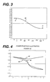
- Figure 3 illustrates a curve of a lens surface wherein a first segment defining a first lens power ends at point a, a second segment defining a second lens power ends at point b, and a transition curve 30 generated pursuant to the present invention connects the first and second power surfaces.
- Figure 4 illustrates an example of a power function of 1.8, and illustrates curves of the power function 40, a correction factor 42, and the power function and correction factor combined 44.
- Figure 6 illustrates a sinusoidal function 60 and a sinusoidal function 62 modified pursuant to the present invention.
- the present invention provides intermediate transition zone functions to maintain a smooth surface profile on lens surfaces such as contact lens surfaces, particularly toric contact lens surfaces, thus giving a uniform repeatable fit throughout the power range.
- the design accounts for a variable optic zone junction thickness with a constant lenticular junction thickness.
- the optic zone junction thickness herein defined as the radial lens thickness at the edge of the front optic zone, varies with designed lens power. This is generally of no consequence in an ordinary symmetrical (rotational) design. However, for rotationally stabilized designs, such as are used in torics, there is a requirement for consistent and repeatable fits across a broad power range.
- the present invention addresses this by allowing the stabilization system to maintain constant aspect/thickness ratios (the ratio between the vertical thickness and the borizontal thickness), and for a smooth transition between the required thick central optic zone, and the peripheral curves/stabilization system (quantify the slab off zone).
- the curves pursuant to the present invention can be placed on the front or back surface of the lens, as required, but are preferably placed on the front surface.
- Figure 7 is a plan view of a toric contact lens 70 having a transition zone 76 designed pursuant to the teachings of the present invention.
- a central optic zone 72 of the lens having a toric surface is connected to a lenticular (nonoptical) zone 74 of the lens by a transition curve or zone 76 pursuant to the present invention.
- the lens includes upper and lower slab off areas 78 in the lenticular zone to provide eyelid induced rotational and positional stabilization of the toric lens.
- the present invention can provide contact lens designs with a thinner peripheral region and a thicker central region, and can provide a unitary one-piece design for a hydrogel contact lens with a thicker and stiffer central region smoothly connected to a thin periphery region for use with an astigmatic patient.
- Figure 8 illustrates a further example of a contact lens 80 for an astigmatic patient designed pursuant to the present invention wherein a thicker central optical zone 82 of the contact lens is connected to a thinner peripheral lenticular (nonoptical) zone 84 of the contact lens with a transition curve 86 pursuant to the present invention.
- the contact lens 80 includes a lens back curve 88, an optical zone front curve 90, a control front curve 92, and a control center thickness 94.
- Figure 9 is an enlarged view of one possible transition curve for the lens of Figure 8 having a first set of multiple radii r1, r2, r3, and a second set of multiple radii with a reverse curve, -r3, -r2, -r1.
- the exemplary contact lens of Figure 8 provides a thicker central region for function and handleability and also provides a reduction in thickness at the peripheral regions beyond the edge of the optical zone for increased comfort as it fits under the eyelids better.
Abstract
Description
- The present invention relates generally to programmable smooth junctions on lenses and molds therefor, particularly for toric lens designs. More particularly, the subject invention pertains to the designs of lenses and also the molds therefor, particularly for toric lens designs, which enable a numerically controlled (NC) machine to be programmed to machine smooth junctions or transitions between adjacent regions of the lens which have different thicknesses or radii of curvature. The subject invention provides precise numerically defined, smooth, near tangential transitions between adjacent regions of a contact lens of different thickness or radius and also of the mold therefor.
- Fanti U.S. Patent 4,095,878 discusses automatic orientation but does not discuss transition zones.
- Accordingly, it is a primary object of the present invention to provide programmable smooth junctions on lenses and molds therefor, particularly for toric lens designs. More particularly, the subject invention provides the design of a lens and also a mold therefor, particularly for toric lens designs, which enables a numerically controlled (NC) machine to be programmed to machine smooth, near tangential junctions or transitions between adjacent regions of the lens which have different thicknesses or radii of curvature.
- A further object of the subject invention is the provision of a precise, numerically defined and numerically controlled (NC) machinable, smooth near tangential transition between adjacent regions on a contact lens of different thickness or radius.
- In accordance with the teachings herein, the present invention provides a method of designing a lens which enables a numerically controlled machine to be programmed to machine smooth transitions between adjacent regions of the lens which have different thicknesses or radii of curvature. The method defines first and second mathematical functions f(a) and f(b) which specify the curves of first and second segments of the lens surface. The slope dy/dx is derived of the first and second mathematical functions at the transition between the first and second segments of the lens surface. A mathematical function is defined which describes a desired transition between the first and second segments of the lens. The first and second mathematical functions f(a) and f(b), the derived slopes dy/dx of the first and second mathematical functions f(a) and f(b), and the mathematical function describing the desired transition are then utilized to program a numerically controlled machine to machine the first and second segments of the lens surface and the desired transition between the first and second segments.
- In greater detail, the x and y intervals between the two functions f(a) and f(b) are normalized to +/-1 into the transition gap between the first and second segments of the lens surface. The mathematical function describing the transition can describe a linear function, a single bridge radius, multiple radii, an aspheric radius, multiple aspheric radii, mixed multiple spheric and aspheric radii, or multiple radii with a reverse curve. The present invention also pertains to a contact lens, such as a contact lens having a toric surface, produced according to the method herein.
- The foregoing objects and advantages of the present invention for programmable smooth junctions on lenses may be more readily understood by one skilled in the art with reference being had to the following detailed description of several preferred embodiments thereof, taken in conjunction with the accompanying drawings wherein like elements are designated by identical reference numerals throughout the several views, and in which:
- Figure 1 illustrates the trigonometric relationships of the slope of a curve to a general x, y cartesian coordinate system;
- Figure 2 illustrates, in an x, y cartesian coordinate system, a general problem approached by the present invention, wherein a first function f(a) defines the curve of a first segment of a lens surface and a second function f(b) defines the curve of a second segment of a lens surface, and the present invention provides a smooth, near tangential correction factor or transition between the first and second functions which can be used to program a numerically controlled machine to machine the first and second functions and the transition;
- Figure 3 illustrates a curve of a lens surface having a first segment defining a first lens power and a second segment defining a second lens power, and wherein a transition curve generated pursuant to the present invention connects the first and second segments;
- Figure 4 illustrates curves of a power function, a correction factor, and the combined power function and correction factor;
- Figure 5 illustrates a second order asymptotic function and a second order asymptotic function modified pursuant to the present invention;
- Figure 6 illustrates a sinusoidal function and a sinusoidal function modified pursuant to the present invention;
- Figure 7 is a plan view of a contact lens designed pursuant to the teachings of the present invention wherein a central optic zone of the lens is connected to a lenticular (nonoptical) zone of the lens by a transition curve or zone pursuant to the present invention;
- Figure 8 illustrates a further example of a contact lens designed pursuant to the present invention wherein a thicker central optical zone of the contact lens is connected to a thinner peripheral lenticular (nonoptical) zone of the contact lens with a transition curve pursuant to the present invention; and
- Figure 9 is an enlarged view of one possible transition curve for the lens of Figure 8 having multiple radii with a reverse curve.
- Referring to the drawings in detail, Figure 1 illustrates the trigonometric relationships of the slope of a curve to a general x, y cartesian coordinate system, and in particular, illustrates a circle with a radius r, and a semichord x which intersects the circle at tangential point c. If a vertical is dropped at tangential point c to translate x to the x axis, then the slope of the angle between the normal to the circle at tangential point c and the x axis is as follows, wherein α is the angle of the normal at point c.

⊥ is the slope of the normal at point c.


- Figure 2 illustrates, in an x, y cartesian coordinate system, a general problem approached by the present invention, wherein a first function f(a) defines the curve of a first segment of a lens surface and a second function f(b) defines the curve of a second segment of a lens surface, and the present invention defines a smooth, near tangential correction factor or transition between the first and second functions which can be used to program a numerically controlled machine to machine the first and second functions and the transition. The functions f(a) and f(b) can be any conic function, particularly for toric lens designs.
- A general conic equation which describes all conics, including spheres, parabolas, ellipses and hyperbola is:

- k = 0 for a sphere,
- k = -1 for a parabola,
- 0 > k > -1 for an ellipse,
- k < -1 for a hyperbola.
- For the first quadrant,

- Accordingly, for the example illustrated in Figure 2, the slope dy/dx of each of the two curves f(a) and f(b) near the intersection of the two curves (at point a for function f(a) and at point b for function f(b)) can be described mathematically. Then the two curves are connected by mathematically describing a function connecting the two known slopes, such that a numerically controlled diamond tipped milling machine can machine the smooth transition in a mold for the lens.
- Referring to Figure 2,
the slope
the slope
- Figure 2 shows the connecting points. Any of several connection functions, and possibly connection functions modified by a correction factor can be used to connect the two points a and b. The connection functions can be a power function, an asymptotic function, or a trigonometric function. In addition, any of these connection functions can be modified by a correction factor such as a linear correction factor, a v-shaped correction factor, an arc correction factor, or a conic correction factor. Accordingly, a selected connection function connecting the two known curves is defined by an equation mathematically specifying the connection function.
- For a power function with a slope down, as illustrated by the example in Figure 4, for


- Similarly, for a power function with a slope up, which is opposite to the illustration of Figure 4, for


- In these equations, the x interval between the two functions f(a) and f(b) can be normalized into the gap, and can be normalized to +/-1, where xo is the x midpoint of the gap, as illustrated in Figure 2.
- The variable y is self-normalized to +/-1 by the equation for the power function since lim f(x) = ± 1 as x -> ± 1.
- For a power function, the function at any point is


- Thus, referring to Figure 2, the connection function between the known functions f(a) and f(b) is defined by an equation wherein x and y have been normalized to +/-1.
- For the points a, b and o in Figure 2,


- For a linear correction factor

- For an aspheric correction factor, the previous conic equation can be used, namely

- k = 0 for a sphere,
- k = -1 for a parabola,
- 0 > k > -1 for an ellipse,
- k < -1 for a hyperbola.
- For an asymmetrical correction function, the asymmetrical function is described by the appropriate mathematical function, such that the numerically controlled machine can follow the mathematical function.
- For an asymptotic connection function equation,

- for slope down
where - Q = 0 or 2 or 4
- if Q = 0 line
- if Q = 2 the start and stop slopes are .-5
- if Q = 4 the start and stop slopes are 0
- Figure 3 illustrates a curve of a lens surface wherein a first segment defining a first lens power ends at point a, a second segment defining a second lens power ends at point b, and a
transition curve 30 generated pursuant to the present invention connects the first and second power surfaces. - Figure 4 illustrates an example of a power function of 1.8, and illustrates curves of the
power function 40, acorrection factor 42, and the power function and correction factor combined 44. - Figure 5 illustrates a second order asymptotic function 50 (wherein Q=2 in the above equation) and a second order
asymptotic function 52 modified pursuant to the present invention. - Figure 6 illustrates a
sinusoidal function 60 and asinusoidal function 62 modified pursuant to the present invention. - The present invention provides intermediate transition zone functions to maintain a smooth surface profile on lens surfaces such as contact lens surfaces, particularly toric contact lens surfaces, thus giving a uniform repeatable fit throughout the power range. The design accounts for a variable optic zone junction thickness with a constant lenticular junction thickness.
- The optic zone junction thickness, herein defined as the radial lens thickness at the edge of the front optic zone, varies with designed lens power. This is generally of no consequence in an ordinary symmetrical (rotational) design. However, for rotationally stabilized designs, such as are used in torics, there is a requirement for consistent and repeatable fits across a broad power range. The present invention addresses this by allowing the stabilization system to maintain constant aspect/thickness ratios (the ratio between the vertical thickness and the borizontal thickness), and for a smooth transition between the required thick central optic zone, and the peripheral curves/stabilization system (quantify the slab off zone). The curves pursuant to the present invention can be placed on the front or back surface of the lens, as required, but are preferably placed on the front surface.
- Figure 7 is a plan view of a
toric contact lens 70 having atransition zone 76 designed pursuant to the teachings of the present invention. In this exemplary embodiment, acentral optic zone 72 of the lens having a toric surface is connected to a lenticular (nonoptical)zone 74 of the lens by a transition curve orzone 76 pursuant to the present invention. The lens includes upper and lower slab offareas 78 in the lenticular zone to provide eyelid induced rotational and positional stabilization of the toric lens. - The present invention can provide contact lens designs with a thinner peripheral region and a thicker central region, and can provide a unitary one-piece design for a hydrogel contact lens with a thicker and stiffer central region smoothly connected to a thin periphery region for use with an astigmatic patient.
- Figure 8 illustrates a further example of a
contact lens 80 for an astigmatic patient designed pursuant to the present invention wherein a thicker centraloptical zone 82 of the contact lens is connected to a thinner peripheral lenticular (nonoptical)zone 84 of the contact lens with atransition curve 86 pursuant to the present invention. Thecontact lens 80 includes a lens backcurve 88, an opticalzone front curve 90, acontrol front curve 92, and acontrol center thickness 94. - Figure 9 is an enlarged view of one possible transition curve for the lens of Figure 8 having a first set of multiple radii r1, r2, r3, and a second set of multiple radii with a reverse curve, -r3, -r2, -r1.
- The exemplary contact lens of Figure 8 provides a thicker central region for function and handleability and also provides a reduction in thickness at the peripheral regions beyond the edge of the optical zone for increased comfort as it fits under the eyelids better.
- In the embodiment of Figure 8:
- 1. The control design has a fixed base curve and a front curve based upon the desired center thickness and desired final power. This design specifies an annulus from point A to point B, Figure 8.
- 2. The central thickness design is based upon the same base curve as the control design with a front curve based upon the thick central thickness and desired final power. This design is found in the central region of the lens and extends to point A. The radius of this zone ≠ the radius of the control region.
- 3. A transition region A - B forms a smooth transition between FC thick and FC thin.
- 4. The transition zone can be:
- a straight line;
- a single bridge radius;
- multiple radii;
- an aspherical radius;
- multiple aspherical radii;
- mixed multiple spherical and aspheric radii; or
- multiple radii with a reverse curve, as illustrated in Figure 9, to minimize discontinuities.
- 5. In a second design mode, the transition occurs at point A in the bright or midrange pupil diameters (region from approximately 2.75-5.75 mm).
- While several embodiments and variations of the present invention for programmable smooth junctions on lenses are described in detail herein, it should be apparent that the disclosure and teachings of the present invention will suggest many alternative designs to those skilled in the art.


Claims (16)
- A method of designing a lens which enables a numerically controlled machine to be programmed to machine smooth transitions between adjacent regions of the lens which have different thicknesses or radii of curvature, comprising:a. defining a first mathematical function f(a) which specifies the curve of a first segment of a lens surface;b. defining a second mathematical function f(b) which specifies the curve of a second segment of the lens surface;c. deriving the slope dy/dx of the first mathematical function f(a) at the transition between the first and second segments of the lens surface;d. deriving the slope dy/dx of the second mathematical function f(b) at the transition between the first and second segments of the lens surface;e. defining a mathematical function which describes a desired transition between the first and second segments of the lens;f. utilizing the first and second mathematical functions f(a) and f(b), the derived slopes dy/dx of the first and second mathematical functions f(a) and f(b), and the mathematical function describing the desired transition to program a numerically controlled machine to machine the first and second segments of the lens surface and the desired transition between the first and second segments.
- A method of designing a lens as claimed in claim 1, further including:a. normalizing the x interval between the two functions f(a) and f(b) into the gap between the first and second segments of the lens surface;b. normalizing the y interval between the two functions f(a) and f(b) into the gap between the first and second segments of the lens surface;
- A method of designing a lens as claimed in claim 2, wherein the normalizing of the x interval and the normalizing of the y interval is to +/-1.
- A method of designing a lens as claimed in claim 1, wherein the mathematical function describing the transition describes a linear function.
- A method of designing a lens as claimed in claim 1, wherein the mathematical function describing the transition describes a single bridge radius.
- A method of designing a lens as claimed in claim 1, wherein the mathematical function describing the transition describes multiple radii.
- A method of designing a lens as claimed in claim 1, wherein the mathematical function describing the transition describes an aspheric radius.
- A method of designing a lens as claimed in claim 1, wherein the mathematical function describing the transition describes multiple aspheric radii.
- A method of designing a lens as claimed in claim 1, wherein the mathematical function describing the transition describes mixed multiple spheric and aspheric radii.
- A method of designing a lens as claimed in claim 1, wherein the mathematical function describing the transition describes multiple radii with a reversed curve.
- A method of designing a lens as claimed in claim 1, wherein a thicker central optical zone of the contact lens is connected to a thinner peripheral lenticular zone of the contact lens with a defined transition curve.
- A method of designing a lens as claimed in claim 1, wherein a control design defines a fixed base curve and a front curve based upon the desired center thickness and a desired optical power, and a transition is specified from the front curve to the lenticular junction of the lens, wherein the central thickness design is based upon the same base curve as the control design, and the front curve is based upon the center thickness and desired optical power.
- A method of designing a lens as claimed in claim 1, wherein the mathematical function describing the transition describes a power function.
- A method of designing a lens as claimed in claim 1, wherein the mathematical function describing the transition describes an asymptotic connection function.
- A method of designing a lens as claimed in claim 1, wherein the mathematical function describing the transition describes a trigonometric function.
- A contact lens produced according to the method of claim 1.
Applications Claiming Priority (2)
| Application Number | Priority Date | Filing Date | Title |
|---|---|---|---|
| US08/433,739 US5650838A (en) | 1995-05-04 | 1995-05-04 | Programmable smooth junctions on lenses |
| US433739 | 1995-05-04 |
Publications (2)
| Publication Number | Publication Date |
|---|---|
| EP0742462A2 true EP0742462A2 (en) | 1996-11-13 |
| EP0742462A3 EP0742462A3 (en) | 1998-11-04 |
Family
ID=23721351
Family Applications (1)
| Application Number | Title | Priority Date | Filing Date |
|---|---|---|---|
| EP96303123A Withdrawn EP0742462A3 (en) | 1995-05-04 | 1996-05-03 | Programmable smooth junctions on lenses |
Country Status (7)
| Country | Link |
|---|---|
| US (1) | US5650838A (en) |
| EP (1) | EP0742462A3 (en) |
| JP (1) | JP3816580B2 (en) |
| AU (1) | AU692691B2 (en) |
| CA (1) | CA2175633C (en) |
| SG (1) | SG48438A1 (en) |
| TW (1) | TW334515B (en) |
Cited By (24)
| Publication number | Priority date | Publication date | Assignee | Title |
|---|---|---|---|---|
| WO1998000749A1 (en) * | 1996-07-01 | 1998-01-08 | Polymer Technology Corporation | Contact lens and method for making the same |
| GB2327283A (en) * | 1997-06-04 | 1999-01-20 | Bausch & Lomb | Manufacture of a rigid contact lens with a smooth, aspherical back surface |
| EP0938693A1 (en) * | 1997-04-17 | 1999-09-01 | Sola International Holdings, Ltd. | Lenses and spectacles bearing lenses |
| EP0988574A1 (en) * | 1997-07-18 | 2000-03-29 | Sola International Holdings, Ltd. | Lens with surface correction |
| WO2000048036A1 (en) * | 1999-02-13 | 2000-08-17 | Contact Lens Precision Laboratories Limited | Contact lenses and methods of manufacture |
| WO2000058773A1 (en) * | 1999-03-25 | 2000-10-05 | Johnson & Johnson Vision Care, Inc. | Contact lenses with contoured edges |
| WO2001033284A1 (en) * | 1999-11-03 | 2001-05-10 | Johnson & Johnson Vision Care, Inc. | Contact lens useful for avoiding dry eye |
| WO2001035157A1 (en) * | 1999-11-11 | 2001-05-17 | Johnson & Johnson Vision Care, Inc. | Contact lenses for large pupils |
| EP1316836A1 (en) * | 2001-11-30 | 2003-06-04 | Menicon Co., Ltd. | Contact lens and method of designing the same |
| EP1340114A1 (en) * | 2000-11-10 | 2003-09-03 | Ocular Sciences Inc. | Junctionless ophthalmic lenses and methods for making same |
| WO2004011991A1 (en) * | 2002-07-31 | 2004-02-05 | Bausch & Lomb Incorporated | Contact lenses having smoothly joined optical surfaces |
| WO2005116730A1 (en) | 2004-05-20 | 2005-12-08 | Johnson & Johnson Vision Care, Inc. | Methods for rotationally stabilizing contact lenses |
| US7036930B2 (en) | 2003-10-27 | 2006-05-02 | Johnson & Johnson Vision Care, Inc. | Methods for reducing corneal staining in contact lens wearers |
| WO2006054970A1 (en) * | 2004-11-12 | 2006-05-26 | Johnson & Johnson Vision Care, Inc. | Methods for reducing corneal staining in contact lens wearers |
| US7152975B2 (en) | 2000-11-10 | 2006-12-26 | Cooper Vision, Inc. | Junctionless ophthalmic lenses and methods for making same |
| WO2009020963A1 (en) * | 2007-08-07 | 2009-02-12 | Novartis Ag | Toric contact lens with improved posterior surface design |
| FR2921163A1 (en) * | 2007-09-19 | 2009-03-20 | Precilens Sa Lab | STABILIZED CONTACT LENS. |
| AU2012202279B2 (en) * | 2004-11-12 | 2012-06-07 | Johnson & Johnson Vision Care, Inc. | Methods for reducing corneal staining in contact lens wearers |
| US8646908B2 (en) | 2008-03-04 | 2014-02-11 | Johnson & Johnson Vision Care, Inc. | Rotationally stabilized contact lenses and methods for their design |
| US8652205B2 (en) | 2009-10-26 | 2014-02-18 | Novartis Ag | Phase-shifted center-distance diffractive design for ocular implant |
| CN105700466A (en) * | 2015-11-23 | 2016-06-22 | 上海交通大学 | Curvature fairing method for high-speed numerical control processing track |
| CN103543539B (en) * | 2004-11-12 | 2016-08-10 | 庄臣及庄臣视力保护公司 | A kind of method that cornea reducing contact lens wearer pollutes |
| EP3559732A4 (en) * | 2016-12-23 | 2020-08-19 | Capricornia Contact Lens Pty Ltd | Contact lens |
| WO2023168482A1 (en) * | 2022-03-09 | 2023-09-14 | Nthalmic Holding Pty Ltd | A method to design toric contact lenses |
Families Citing this family (14)
| Publication number | Priority date | Publication date | Assignee | Title |
|---|---|---|---|---|
| US7922323B2 (en) * | 1995-10-18 | 2011-04-12 | Scientific Optics, Inc. | Method and apparatus for improving vision |
| US6149609A (en) * | 1995-10-18 | 2000-11-21 | Scientific Optics, Inc. | Method and apparatus for improving vision |
| US5807381A (en) * | 1995-10-18 | 1998-09-15 | Scientific Optics, Inc. | Method and apparatus for improving vision |
| CN100399107C (en) | 1996-03-21 | 2008-07-02 | 索拉国际控股有限公司 | Improved single vision lenses |
| EP1103014A4 (en) | 1998-08-06 | 2006-09-06 | John B W Lett | Multifocal aspheric lens |
| JP2002532751A (en) | 1998-12-16 | 2002-10-02 | ウェズリー ジェッセン コーポレイション | Aspheric multifocal contact lens |
| US6176579B1 (en) * | 1999-07-07 | 2001-01-23 | Softfocal Co., Inc | Bifocal contact lens with toric transition |
| US6474814B1 (en) | 2000-09-08 | 2002-11-05 | Florida Optical Engineering, Inc | Multifocal ophthalmic lens with induced aperture |
| CN101341435B (en) * | 2005-12-22 | 2012-05-30 | 博士伦公司 | Toric contact lenses |
| US9217854B2 (en) * | 2009-04-28 | 2015-12-22 | Cree, Inc. | Lens with controlled light refraction |
| CA2812206C (en) | 2010-09-27 | 2018-08-21 | Johnson & Johnson Vision Care, Inc. | Translating presbyopic contact lens |
| AU2011307358B2 (en) * | 2010-09-27 | 2014-06-12 | Johnson & Johnson Vision Care, Inc. | Asymmetric translating presbyopic contact lens |
| US9170434B2 (en) | 2010-09-27 | 2015-10-27 | Johnson & Johnson Vision Care, Inc. | Translating presbyopic contact lens |
| US11567346B2 (en) | 2016-02-10 | 2023-01-31 | Visioneering Technologies, Inc. | Induced aperture lens and method |
Citations (4)
| Publication number | Priority date | Publication date | Assignee | Title |
|---|---|---|---|---|
| WO1988009950A1 (en) * | 1987-06-01 | 1988-12-15 | Valdemar Portney | Multifocal ophthalmic lens |
| US5106180A (en) * | 1991-05-30 | 1992-04-21 | Robert Marie | Multifocal ophthalmic lens |
| US5125729A (en) * | 1991-05-03 | 1992-06-30 | Les Laboratoires Opti-Centre Inc. | Multifocal contact lens |
| CA2096706A1 (en) * | 1993-05-20 | 1994-11-21 | Robert Mercure | Soft toric lens for correction of astigmatism |
Family Cites Families (12)
| Publication number | Priority date | Publication date | Assignee | Title |
|---|---|---|---|---|
| US3822089A (en) * | 1968-09-25 | 1974-07-02 | Akademie Ved | Contact lens blank or replica made from anhydrous, sparingly cross-linked hydrophilic copolymers |
| US3973837A (en) * | 1971-05-04 | 1976-08-10 | Page Louis J | Contact lenses |
| US3944347A (en) * | 1971-06-11 | 1976-03-16 | E. I. Du Pont De Nemours & Co. | Contact lens having a hard center and soft, tough periphery |
| US4055379A (en) * | 1973-08-16 | 1977-10-25 | American Optical Corporation | Multifocal lens |
| US4095878A (en) * | 1974-03-28 | 1978-06-20 | Titmus Eurocon Kontaktlinsen Gmbh & Co. Kg | Soft contact lens with flattened region for automatic orientation |
| US4121885A (en) * | 1974-04-29 | 1978-10-24 | Precision Cosmet Co., Inc. | Method to produce a composite contact lens |
| DE3016935C2 (en) * | 1980-05-02 | 1991-01-24 | Fa. Carl Zeiss, 7920 Heidenheim | Multifocal spectacle lens with partially sliding refractive power |
| US4676610A (en) * | 1983-07-22 | 1987-06-30 | Sola International Holdings Ltd. | Method of making progressive lens surface and resulting article |
| US5166711A (en) * | 1987-06-01 | 1992-11-24 | Valdemar Portney | Multifocal ophthalmic lens |
| FR2632079B1 (en) * | 1988-05-27 | 1990-09-28 | Capez Pierre | MULTIFOCAL CONTACT LENS |
| US5112351A (en) * | 1990-10-12 | 1992-05-12 | Ioptex Research Inc. | Multifocal intraocular lenses |
| US5446508A (en) * | 1994-02-18 | 1995-08-29 | Bmc Industries, Inc. | Progressive power lens |
-
1995
- 1995-05-04 US US08/433,739 patent/US5650838A/en not_active Expired - Lifetime
-
1996
- 1996-04-29 AU AU51947/96A patent/AU692691B2/en not_active Ceased
- 1996-05-02 CA CA002175633A patent/CA2175633C/en not_active Expired - Fee Related
- 1996-05-02 JP JP13600596A patent/JP3816580B2/en not_active Expired - Fee Related
- 1996-05-03 EP EP96303123A patent/EP0742462A3/en not_active Withdrawn
- 1996-05-04 SG SG1996009714A patent/SG48438A1/en unknown
- 1996-05-27 TW TW085106250A patent/TW334515B/en active
Patent Citations (4)
| Publication number | Priority date | Publication date | Assignee | Title |
|---|---|---|---|---|
| WO1988009950A1 (en) * | 1987-06-01 | 1988-12-15 | Valdemar Portney | Multifocal ophthalmic lens |
| US5125729A (en) * | 1991-05-03 | 1992-06-30 | Les Laboratoires Opti-Centre Inc. | Multifocal contact lens |
| US5106180A (en) * | 1991-05-30 | 1992-04-21 | Robert Marie | Multifocal ophthalmic lens |
| CA2096706A1 (en) * | 1993-05-20 | 1994-11-21 | Robert Mercure | Soft toric lens for correction of astigmatism |
Cited By (44)
| Publication number | Priority date | Publication date | Assignee | Title |
|---|---|---|---|---|
| US5975694A (en) * | 1996-07-01 | 1999-11-02 | Bausch & Lomb Incorporated | Contact lens and method for making the same |
| WO1998000749A1 (en) * | 1996-07-01 | 1998-01-08 | Polymer Technology Corporation | Contact lens and method for making the same |
| EP0938693A1 (en) * | 1997-04-17 | 1999-09-01 | Sola International Holdings, Ltd. | Lenses and spectacles bearing lenses |
| EP0938693A4 (en) * | 1997-04-17 | 1999-10-13 | ||
| GB2327283B (en) * | 1997-06-04 | 2002-02-27 | Bausch & Lomb | Manufacture of contact lenses |
| GB2327283A (en) * | 1997-06-04 | 1999-01-20 | Bausch & Lomb | Manufacture of a rigid contact lens with a smooth, aspherical back surface |
| EP0988574A1 (en) * | 1997-07-18 | 2000-03-29 | Sola International Holdings, Ltd. | Lens with surface correction |
| EP0988574A4 (en) * | 1997-07-18 | 2000-03-29 | Sola Int Holdings | Lens with surface correction |
| GB2364138A (en) * | 1999-02-13 | 2002-01-16 | Contact Lens Prec Lab Ltd | Contact lenses and methods of manufacture |
| GB2364138B (en) * | 1999-02-13 | 2003-09-03 | Contact Lens Prec Lab Ltd | Contact lenses and methods of manufacture |
| WO2000048036A1 (en) * | 1999-02-13 | 2000-08-17 | Contact Lens Precision Laboratories Limited | Contact lenses and methods of manufacture |
| US6206520B1 (en) | 1999-03-25 | 2001-03-27 | Johnson & Johnson Vision Care, Inc. | Contact lenses with contoured edges |
| WO2000058773A1 (en) * | 1999-03-25 | 2000-10-05 | Johnson & Johnson Vision Care, Inc. | Contact lenses with contoured edges |
| WO2001033284A1 (en) * | 1999-11-03 | 2001-05-10 | Johnson & Johnson Vision Care, Inc. | Contact lens useful for avoiding dry eye |
| US6364482B1 (en) | 1999-11-03 | 2002-04-02 | Johnson & Johnson Vision Care, Inc. | Contact lens useful for avoiding dry eye |
| WO2001035157A1 (en) * | 1999-11-11 | 2001-05-17 | Johnson & Johnson Vision Care, Inc. | Contact lenses for large pupils |
| US7828431B2 (en) | 2000-11-10 | 2010-11-09 | Coopervision International Holding Company, Lp | Junctionless ophthalmic lenses and methods for making same |
| EP1340114A4 (en) * | 2000-11-10 | 2005-03-02 | Ocular Sciences Inc | Junctionless ophthalmic lenses and methods for making same |
| EP1340114A1 (en) * | 2000-11-10 | 2003-09-03 | Ocular Sciences Inc. | Junctionless ophthalmic lenses and methods for making same |
| US7152975B2 (en) | 2000-11-10 | 2006-12-26 | Cooper Vision, Inc. | Junctionless ophthalmic lenses and methods for making same |
| US6726323B2 (en) | 2001-11-30 | 2004-04-27 | Menicon Co., Ltd. | Contact lens and method of designing the same |
| EP1316836A1 (en) * | 2001-11-30 | 2003-06-04 | Menicon Co., Ltd. | Contact lens and method of designing the same |
| WO2004011991A1 (en) * | 2002-07-31 | 2004-02-05 | Bausch & Lomb Incorporated | Contact lenses having smoothly joined optical surfaces |
| US6843563B2 (en) | 2002-07-31 | 2005-01-18 | Bausch And Lomb, Inc. | Smoothly blended optical surfaces |
| CN100343728C (en) * | 2002-07-31 | 2007-10-17 | 博士伦公司 | Contact lenses having smoothly joined optical surfaces |
| US7036930B2 (en) | 2003-10-27 | 2006-05-02 | Johnson & Johnson Vision Care, Inc. | Methods for reducing corneal staining in contact lens wearers |
| AU2005248779B2 (en) * | 2004-05-20 | 2010-04-29 | Johnson & Johnson Vision Care, Inc. | Methods for rotationally stabilizing contact lenses |
| WO2005116730A1 (en) | 2004-05-20 | 2005-12-08 | Johnson & Johnson Vision Care, Inc. | Methods for rotationally stabilizing contact lenses |
| US7201480B2 (en) | 2004-05-20 | 2007-04-10 | Johnson & Johnson Vision Care, Inc. | Methods for rotationally stabilizing contact lenses |
| AU2012202279B2 (en) * | 2004-11-12 | 2012-06-07 | Johnson & Johnson Vision Care, Inc. | Methods for reducing corneal staining in contact lens wearers |
| WO2006054970A1 (en) * | 2004-11-12 | 2006-05-26 | Johnson & Johnson Vision Care, Inc. | Methods for reducing corneal staining in contact lens wearers |
| CN103543539B (en) * | 2004-11-12 | 2016-08-10 | 庄臣及庄臣视力保护公司 | A kind of method that cornea reducing contact lens wearer pollutes |
| WO2009020963A1 (en) * | 2007-08-07 | 2009-02-12 | Novartis Ag | Toric contact lens with improved posterior surface design |
| AU2008309486B2 (en) * | 2007-09-19 | 2014-06-19 | Laboratoire Precilens | Contact lens |
| WO2009047411A3 (en) * | 2007-09-19 | 2009-06-04 | Precilens Lab | Contact lens |
| FR2921163A1 (en) * | 2007-09-19 | 2009-03-20 | Precilens Sa Lab | STABILIZED CONTACT LENS. |
| US8162476B2 (en) | 2007-09-19 | 2012-04-24 | Laboratoire Precilens | Contact lens |
| WO2009047411A2 (en) * | 2007-09-19 | 2009-04-16 | Laboratoire Precilens | Contact lens |
| US8646908B2 (en) | 2008-03-04 | 2014-02-11 | Johnson & Johnson Vision Care, Inc. | Rotationally stabilized contact lenses and methods for their design |
| US8652205B2 (en) | 2009-10-26 | 2014-02-18 | Novartis Ag | Phase-shifted center-distance diffractive design for ocular implant |
| CN105700466A (en) * | 2015-11-23 | 2016-06-22 | 上海交通大学 | Curvature fairing method for high-speed numerical control processing track |
| EP3559732A4 (en) * | 2016-12-23 | 2020-08-19 | Capricornia Contact Lens Pty Ltd | Contact lens |
| US11415816B2 (en) | 2016-12-23 | 2022-08-16 | Capricornia Contact Lens Pty Ltd | Contact lens |
| WO2023168482A1 (en) * | 2022-03-09 | 2023-09-14 | Nthalmic Holding Pty Ltd | A method to design toric contact lenses |
Also Published As
| Publication number | Publication date |
|---|---|
| JPH0934526A (en) | 1997-02-07 |
| EP0742462A3 (en) | 1998-11-04 |
| JP3816580B2 (en) | 2006-08-30 |
| AU692691B2 (en) | 1998-06-11 |
| SG48438A1 (en) | 1998-04-17 |
| MX9601677A (en) | 1997-07-31 |
| AU5194796A (en) | 1996-11-14 |
| US5650838A (en) | 1997-07-22 |
| CA2175633A1 (en) | 1996-11-05 |
| TW334515B (en) | 1998-06-21 |
| CA2175633C (en) | 2007-02-27 |
Similar Documents
| Publication | Publication Date | Title |
|---|---|---|
| EP0742462A2 (en) | Programmable smooth junctions on lenses | |
| US6808262B2 (en) | Multifocal contact lens with aspheric surface | |
| CA2281273C (en) | Progressive addition lenses | |
| CA1135544A (en) | Ophthalmic progressive power lens and method of making same | |
| AU577638B2 (en) | Weighted contact lenses | |
| EP1527366B1 (en) | Toric multifocal contact lenses | |
| US6176579B1 (en) | Bifocal contact lens with toric transition | |
| US5137343A (en) | Multifocal surface for a multifocal spectacle lens | |
| EP0578833A1 (en) | Variable focus visual power correction apparatus | |
| EP1853962B1 (en) | A toric lens design | |
| US4883350A (en) | Contact lens providing a central spherical region bounded by a circumscribing aspherical region | |
| US6874887B2 (en) | Multifocal contact lens | |
| US6871953B1 (en) | Contact lens with transition | |
| WO2001016641A1 (en) | Rotationally stabilized contact lenses | |
| US5835187A (en) | Aspheric multifocal contact lens having concentric front surface | |
| CA2279925A1 (en) | Dynamically stabilized contact lenses | |
| EP0398984A4 (en) | Improved contact lens design | |
| US5975694A (en) | Contact lens and method for making the same | |
| EP1468324B1 (en) | Multifocal ophthalmic lenses | |
| US5815237A (en) | Contact lens and method for making the same | |
| KR100664449B1 (en) | Contact lenses with off-axis bevel | |
| CA2175649A1 (en) | Concentric annular ring lens designs with minimal angles between adjacent annular ring segments | |
| GB2132785A (en) | Thin aphakic contact lens | |
| MXPA96001677A (en) | Programmable soft unions in len | |
| GB1569764A (en) | Progressive power ophthalmic lens |
Legal Events
| Date | Code | Title | Description |
|---|---|---|---|
| PUAI | Public reference made under article 153(3) epc to a published international application that has entered the european phase |
Free format text: ORIGINAL CODE: 0009012 |
|
| AK | Designated contracting states |
Kind code of ref document: A2 Designated state(s): AT BE CH DE DK ES FR GB GR IE IT LI NL PT SE |
|
| PUAL | Search report despatched |
Free format text: ORIGINAL CODE: 0009013 |
|
| AK | Designated contracting states |
Kind code of ref document: A3 Designated state(s): AT BE CH DE DK ES FR GB GR IE IT LI NL PT SE |
|
| 17P | Request for examination filed |
Effective date: 19990412 |
|
| 17Q | First examination report despatched |
Effective date: 20011203 |
|
| STAA | Information on the status of an ep patent application or granted ep patent |
Free format text: STATUS: THE APPLICATION IS DEEMED TO BE WITHDRAWN |
|
| 18D | Application deemed to be withdrawn |
Effective date: 20031209 |