EP0741020A2 - Rotary printing machine having a free mountable folding apparatus - Google Patents
Rotary printing machine having a free mountable folding apparatus Download PDFInfo
- Publication number
- EP0741020A2 EP0741020A2 EP96810254A EP96810254A EP0741020A2 EP 0741020 A2 EP0741020 A2 EP 0741020A2 EP 96810254 A EP96810254 A EP 96810254A EP 96810254 A EP96810254 A EP 96810254A EP 0741020 A2 EP0741020 A2 EP 0741020A2
- Authority
- EP
- European Patent Office
- Prior art keywords
- folder
- printing machine
- machine according
- rotary printing
- cylinder
- Prior art date
- Legal status (The legal status is an assumption and is not a legal conclusion. Google has not performed a legal analysis and makes no representation as to the accuracy of the status listed.)
- Granted
Links
Images


Classifications
-
- B—PERFORMING OPERATIONS; TRANSPORTING
- B65—CONVEYING; PACKING; STORING; HANDLING THIN OR FILAMENTARY MATERIAL
- B65H—HANDLING THIN OR FILAMENTARY MATERIAL, e.g. SHEETS, WEBS, CABLES
- B65H45/00—Folding thin material
- B65H45/12—Folding articles or webs with application of pressure to define or form crease lines
- B65H45/22—Longitudinal folders, i.e. for folding moving sheet material parallel to the direction of movement
- B65H45/221—Longitudinal folders, i.e. for folding moving sheet material parallel to the direction of movement incorporating folding triangles
- B65H45/225—Arrangements of folding triangles
-
- B—PERFORMING OPERATIONS; TRANSPORTING
- B41—PRINTING; LINING MACHINES; TYPEWRITERS; STAMPS
- B41F—PRINTING MACHINES OR PRESSES
- B41F13/00—Common details of rotary presses or machines
- B41F13/0008—Driving devices
-
- B—PERFORMING OPERATIONS; TRANSPORTING
- B41—PRINTING; LINING MACHINES; TYPEWRITERS; STAMPS
- B41F—PRINTING MACHINES OR PRESSES
- B41F13/00—Common details of rotary presses or machines
- B41F13/008—Mechanical features of drives, e.g. gears, clutches
-
- B—PERFORMING OPERATIONS; TRANSPORTING
- B41—PRINTING; LINING MACHINES; TYPEWRITERS; STAMPS
- B41F—PRINTING MACHINES OR PRESSES
- B41F13/00—Common details of rotary presses or machines
- B41F13/54—Auxiliary folding, cutting, collecting or depositing of sheets or webs
- B41F13/56—Folding or cutting
- B41F13/60—Folding or cutting crosswise
Definitions
- the invention relates to a rotary printing press with a folder according to the preamble of claim 1.
- the folders are driven and synchronized by a main drive via a longitudinal shaft.
- a main drive via a longitudinal shaft.
- several printing units and a folder are set up in one line. This is the most cost-effective drive for the longitudinal shaft concept.
- Additional folders, even if they are just back-up folders, are integrated into the overall system.
- FIG. 1 An example of a known drive, for example according to DE 41 27 321 A1, is shown schematically in FIG. 1.
- the coupling from the longitudinal shaft 1.10 to the folding apparatus takes place mechanically via a longitudinal shaft gear box 1, various gear stages 1.20, a shaft 1.23 to an intermediate wheel 1.3 or coupled to a bevel gear 1.24 alternatively to the knife cylinder 2 coupled with a bevel gear 1.24.
- the cylinders 2, 3 and 4 are mechanically coupled with each other via spur gears.
- the disadvantage here is that the cylinders 2, 3 and 4 can take any position with respect to one another and with respect to the longitudinal shaft 1.10 in the region of the tooth play. This is due to the effective moments on the cylinders such as cornering controls, cutting strokes and the like. Irregularities that cannot be avoided as a result are noticeable in the folding tolerances.
- the invention has set itself the task of increasing the flexibility with regard to the configurability of a rotary printing press, insofar as cutting, folding and laying out are concerned.
- a folder of a rotary printing machine with at least one folding jaw cylinder and a knife cylinder, preferably also a collecting cylinder and a delivery, has a drive motor for the individual drive of the folder, which is mechanically coupled only to the folder.
- the folding apparatus can be freely arranged and positioned relative to the printing units and advantageously also for a folding structure and a folding superstructure, without causing additional costs.
- Both folders can be placed at the system level, in particular as left and right folders in a so-called back-to-back arrangement or as double folders with delivery on the same side of the machine.
- the first option is particularly narrow with correspondingly short transfer paths for the train.
- the second variant, i.e. the double folder offers the advantage that both deliveries are on one machine side and two identical folders can be used. Both types of installation allow operation on one level.
- a first folder can also be placed on the plant level, while a second folder is offset in the machine basement. As a result, short web transfer paths and unhindered access to the folders are achieved.
- the overall height is low.
- both folders can be set up in the basement, namely as a double folder with a separate structure mounted on the machine table or as a double folder in a common structure. Because of the arrangement in the reel changer level, both variants are characterized by their low overall height above the machine level. Furthermore, because they are arranged on one level, they are particularly easy to use.
- the folder itself can be moved. If the folding structure and the superstructure are placed on a yoke, a back-up folding apparatus, if one is provided, can be inserted instead of the main folding apparatus if required. Depending on which shifting method is used, no additional space is required in the system. If the machine table itself is used as a yoke construction and the folders are placed in the basement, this also results in a low overall height.
- the fold structure and the fold superstructure can also be arranged to be movable on a yoke construction.
- a drive motor drives onto the folding jaw cylinder via a mechanical coupling, preferably a motor-side pinion and a cylinder-side spur gear.
- a mechanical coupling preferably a motor-side pinion and a cylinder-side spur gear.
- the motor-side pinion meshes with any other gearwheel arranged after the knife cylinder in the drive train of the cylinders of the folder.
- Another variant consists in arranging the drive motor where, according to the prior art, the longitudinal shaft gear box is located.
- the drive motor drives the knife cylinder via a toothed belt.
- the mass of the knife cylinder can be added to the low own mass of the drive motor, whereby the control dynamics can be improved.
- a translation between the drive motor and knife cylinder can also be provided in more than one stage.
- the drive from the motor via a toothed belt to the collecting cylinder is further preferred.
- the mass of the collecting cylinder which is larger than that of the knife cylinder, can be added to the low own mass of the drive motor, which, as already mentioned, improves the control dynamics.
- a multi-stage translation between the drive motor and the collecting cylinder can be preferred.
- Such a toothed belt can also be used to drive the jaw cylinder.
- the drive motor drives via a toothed belt on any gear in the entire drive train between the knife cylinder and the delivery, for example a paddle wheel.
- the drive can also take place on an intermediate wheel that is operatively connected to the drive train.
- the required gear ratio from the drive motor to the gear is advantageous single-stage, so that again a space-saving solution is created.
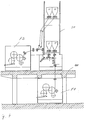
- a printing web B runs through a capping device 20, a pair of traction rollers 21 arranged behind it, over a collecting cylinder 3 with an associated knife cylinder 2, is cut transversely there and then from the collecting cylinder 3 onto the jaw cylinder 4 and from there onto a paddle wheel serving as delivery means 5 passed.
- a paddle wheel serving as delivery means 5 passed.
- an endlessly rotating means of transport with grippers for the folded printed copies can also be provided.
- the jaw cylinder 4 is driven directly by a drive motor 10.
- the mechanical coupling between the drive motor 10 and the jaw cylinder 4 is formed via a motor-side pinion 10.1 and a cylinder-side spur gear 4.1.
- FIG. 3 shows a printing press, which is an example of the gain in flexibility with regard to the installation options of the self-propelled folder.
- a folder F1 is set up in the machine cellar on the same level as roll changer R1, R2, R3 and R4, while printing units D1, D2 and D3 are in alignment on an overlying system level 100.
- a folding structure 30, which has at least one hopper on one or more levels, is arranged above the folding device F1 and is mounted on the folding device.
- the folding superstructures 30, 40 are arranged between the two printing units D2 and D3, so that the printing webs run in from two sides.
- a second folder can be provided.
- This second folder is preferably also arranged at the roll changer level or at the system level 100, preferably approximately in alignment with the lower fold superstructure 30.
- the printing webs can optionally be fed to one of the folders. In the example of FIG. 3, only the folder F1 in the machine basement is in operation. If two folding apparatuses are provided, some of the printing webs that are conveyed further behind the printing units can be fed to the folding structure, as shown by dashed lines as an example.
- the longitudinally folded printing webs then reach the second folder from the upper hopper of the folding assembly 30, while the printing webs folded in the lower hopper of the folding assembly 30 continue to be fed to the first folder F1.
- Fig. 4 shows the installation of the second folder F2 mentioned on the system level 100.
- the first folder F1 is in turn placed in the basement of the machine, on the same level as the roll changers (not shown), while the second folder F2 is laid out next to the machine on one side of the machine is arranged.
- the fold superstructure 30 and 40 with two vertically stacked double formers T is supported in a yoke J.
- the yoke J is in turn stored in FIG. 4 on the system level 100 or the machine table above the first folder F1 and independently of it.
- Between the first folder F1 and its part 30 of the fold superstructure, its part 35 of the fold structure is received in the same yoke J with deflection and tension rollers.
- the corresponding folding assembly part 45 for the second folder F2 is located between the yoke J and the second folder F2. In the upper part of the yoke J, the folding superstructure part 40 for this second folder F2 is received.
- both the storage and the drive of the folding superstructure 30 take place mechanically independently of the drive and the storage of the folding apparatus. The same applies to their fold structure 35, 45.
- Fig. 5 shows two folders F1, F2 arranged side by side on one level - on the machine table or in the machine cellar. Only the first folder F1 is in operation, while the second folder serves as a backup.
- the printing web or webs are fed to the folding device F1 again via a folding structure 30 mounted on a yoke J.
- the yoke J is mounted independently of the folding devices F1 and F2, so that the first folding device F1 is exchanged for the back-up folding device F2 is enabled. Replacing the folder F1 with the back-up folder F2 is particularly easy if the two folders can be moved (F1 ⁇ F1 'or F2 ⁇ F2').
- the printing press has six printing units D1 to D6 on, each of which three printing units, viewed in the web conveying direction, are arranged one behind the other and two such rows of three are set up side by side.
- Folders F1, F2 and F3 are placed to the left and right of the last printing unit D1 and D4 of the two printing unit rows of three such that one of the folding units, F2, is arranged between the last two printing units D1 and D4, so that printing webs from these two Printing units can be fed to the center-mounted, in this case common folder F2.
- the two further folders F1, F2 and F3 are arranged on the free outer sides of each of the printing units D1 and D4.
- each of the folders F1, F2 and F3 there is an associated folder assembly 30 with former or former, while above the two last printing units D1 and D4 next to the former F1 and F3 the necessary deflection rollers and turning bars for feeding the printing web are arranged.
- the folded printed copies can be displayed uniformly in the machine longitudinal direction. However, which in turn demonstrates the flexibility of the solution according to the invention, it can also take place to the sides in the case of the two outer folders F1 and F3.
Abstract
Description
Die Erfindung betrifft eine Rotationsdruckmaschine mit einem Falzapparat nach dem Oberbegriff von Anspruch 1.The invention relates to a rotary printing press with a folder according to the preamble of
Bei herkömmlichen Rotationsdruckmaschinen wird ein bzw. werden die Falzapparate von einem Hauptantrieb über eine Längswelle angetrieben und synchronisiert. Meist werden mehrere Druckwerke und ein Falzapparat in einer Linie aufgestellt. Für das Längswellenkonzept ist dies der kostengünstigste Antrieb. Zusätzliche Falzapparate, auch wenn es sich nur um Back-up Falzapparate handelt, werden in die Gesamtanlage integriert aufgestellt.In conventional rotary printing presses, the folders are driven and synchronized by a main drive via a longitudinal shaft. Usually several printing units and a folder are set up in one line. This is the most cost-effective drive for the longitudinal shaft concept. Additional folders, even if they are just back-up folders, are integrated into the overall system.
Ein Beispiel für einen bekannten Antrieb, beispielsweise nach der DE 41 27 321 A1, ist schematisch in Fig. 1 dargestellt. Hierbei erfolgt die Kopplung von der Längswelle 1.10 zu dem Falzapparat, umfassend einen Messerzylinder 2, einen Sammelzylinder 3 und einen Falzklappenzylinder 4, mechanisch über einen Längswellen-Getriebekasten 1, verschiedene Zahnstufen 1.20, eine Welle 1.23 auf ein mit einem Kegelrad 1.24 gekoppelten Zwischenrad 1.3 oder alternativ auf den mit einem Kegelrad 1.24 gekoppelten Messerzylinder 2. Die Zylinder 2, 3 und 4 sind untereinander mechanisch über Stirnzahnräder gekoppelt. Nachteilig ist hierbei, daß die Zylinder 2, 3 und 4 zueinander und gegenüber der Längswelle 1.10 im Bereich des Zahnspiels eine beliebige Lage einnehmen können. Ursächlich hierfür sind an den Zylindern wirksame Momente wie Kurvensteuerungen, Schnittschlag und dergleichen. Hierdurch nicht vermeidbare Unregelmäßigkeiten machen sich bei den Falztoleranzen bemerkbar.An example of a known drive, for example according to DE 41 27 321 A1, is shown schematically in FIG. 1. Here, the coupling from the longitudinal shaft 1.10 to the folding apparatus, comprising a
Die Erfindung hat es sich zur Aufgabe gemacht, die Flexibilität hinsichtlich der Konfigurierbarkeit einer Rotationsdruckmaschine, soweit das Schneiden, Falzen und Auslegen betroffen ist, zu erhöhen.The invention has set itself the task of increasing the flexibility with regard to the configurability of a rotary printing press, insofar as cutting, folding and laying out are concerned.
Es soll bevorzugt auch die Registereinstellung bei gleichzeitiger Verhinderung, zumindest Verringerung der Falzungenauigkeiten aufgrund des Zahnspiels der Zahnräder im Antriebsstrang des Falzapparats individuell für den Falzapparat vorgenommen werden können.It should also preferably be possible to individually adjust the register for the folder, while at the same time preventing or at least reducing the inaccuracies in the fold due to the tooth play of the gearwheels in the drive train of the folder.
Diese Aufgabe wird durch den Gegenstand von Anspruch 1 gelöst.This object is solved by the subject matter of
Erfindungsgemäß weist ein Falzapparat einer Rotationsdruckmaschine mit wenigstens einem Falzklappenzylinder und einem Messerzylinder, vorzugsweise auch einem Sammelzylinder und einer Auslage, zum Einzelantrieb des Falzapparats einen Antriebsmotor auf, der mechanisch nur mit dem Falzapparat gekoppelt ist.According to the invention, a folder of a rotary printing machine with at least one folding jaw cylinder and a knife cylinder, preferably also a collecting cylinder and a delivery, has a drive motor for the individual drive of the folder, which is mechanically coupled only to the folder.
Wegen der nicht mehr benötigten mechanischen Kopplung mit den Druckwerken ist die freie Anordnung bzw. Stellbarkeit des Falzapparats zu den Druckwerken und vorteilhafterweise auch zu einem Falzaufbau und einem Falzüberbau, ohne zusätzliche Kosten zu verursachen, möglich.Because the mechanical coupling with the printing units is no longer required, the folding apparatus can be freely arranged and positioned relative to the printing units and advantageously also for a folding structure and a folding superstructure, without causing additional costs.
Da bevorzugterweise eine mechanische Verbindung zwischen dem Falzapparat und dem Falzaufbau bzw. dem Falzüberbau auch nicht besteht, ist die Flexibilität auch in der Konfigurierung dieser drei Funktionsgruppen erhöht. So ist beispielsweise eine Zuordnung von lediglich einem Aufbau und einem Überbau zu zwei Falzapparaten möglich.Since preferably a mechanical connection between the folder and the folder structure or the folder superstructure also not there is increased flexibility in the configuration of these three function groups. For example, only one structure and one superstructure can be assigned to two folders.
Zahnspielproblemen wird entgegengewirkt, während der Antriebsmotor für den Falzapparat zum Antrieb der weiteren Komponenten der Druckmaschine elektrisch synchronisiert wird. Der Einzelantrieb erlaubt es, den Falzapparat unabhängig von der Position der Druckwerke auf jede beliebige Falzposition zu drehen und dadurch das Schnittregister auf einfache Weise anzufahren. Dieser Vorteil ist besonders beim Papiereinzug in einen Back-up Falzapparat von Nutzen, da bei solch einem Back-up Falzapparat über eine als Referenz dienende Nullposition des Antriebs das Schnittregister angefahren werden kann. Durch die Erfindung werden die Falztoleranzen minimiert.Backlash problems are counteracted while the drive motor for the folder for driving the other components of the printing machine is electrically synchronized. The single drive allows the folder to be rotated to any folding position regardless of the position of the printing units, thereby making it easy to move to the cutting register. This advantage is particularly useful when feeding paper into a back-up folder, since with such a back-up folder the cutting register can be approached via a zero position of the drive that serves as a reference. The folding tolerances are minimized by the invention.
Falls ein erster und ein zweiter Falzapparat vorgesehen sind, werden folgende Aufstellvarianten bevorzugt:If a first and a second folder are provided, the following setup variants are preferred:
Es können beide Falzapparate auf Anlagenebene plaziert werden, insbesondere als eine linke und eine rechte Falzapparateausführung in sogenannter Back-to-Back-Anordnung oder als Doppel-Falzapparat mit einer Auslage auf die gleiche Seite der Maschine. Die erstgenannte Möglichkeit baut besonders schmal mit dementsprechend kurzen Überführwegen für die Bahn. Die zweite Variante, d.h. der Doppel-Falzapparat, bietet den Vorteil, daß beide Auslagen sich auf einer Maschinenseite befinden und zwei identische Falzapparate verwendet werden können. Beide Aufstellvarianten ermöglichen die Bedienung auf einer Ebene.Both folders can be placed at the system level, in particular as left and right folders in a so-called back-to-back arrangement or as double folders with delivery on the same side of the machine. The first option is particularly narrow with correspondingly short transfer paths for the train. The second variant, i.e. the double folder offers the advantage that both deliveries are on one machine side and two identical folders can be used. Both types of installation allow operation on one level.
Es kann auch ein erster Falzapparat auf Anlageebene plaziert werden, während ein zweiter Falzapparat dazu versetzt im Maschinenkeller steht. Hierdurch werden kurze Bahnüberführwege und ein ungehinderter Zugang zu den Falzapparaten erzielt.A first folder can also be placed on the plant level, while a second folder is offset in the machine basement. As a result, short web transfer paths and unhindered access to the folders are achieved.
Falls hierbei ein Falzaufbau und ein Falzüberbau auf dem Maschinentisch, d.h., auf der Anlagenebene, aufgestellt werden, ergibt sich eine geringe Bauhöhe.If a fold structure and a fold superstructure are set up on the machine table, i.e. on the system level, the overall height is low.
Es können schließlich auch beide Falzapparate im Keller aufgestellt sein, und zwar als Doppel-Falzapparat mit getrenntem und auf dem Maschinentisch gelagerten Aufbau oder als Doppel-Falzapparat in einem gemeinsamen aufgesetzten Aufbau. Beide Varianten zeichnen sich wegen der Anordnung in der Rollenwechslerebene durch ihre geringe Bauhöhe über der Maschinenebene aus. Sie sind desweiteren, da auf einer Ebene angeordnet, besonders gut bedienbar.Finally, both folders can be set up in the basement, namely as a double folder with a separate structure mounted on the machine table or as a double folder in a common structure. Because of the arrangement in the reel changer level, both variants are characterized by their low overall height above the machine level. Furthermore, because they are arranged on one level, they are particularly easy to use.
In allen vorgenannten Ausführungsbeispielen können für mehrere Falzapparate mit Vorteil nur ein Aufbau und ein Überbau vorgesehen sein.In all of the aforementioned exemplary embodiments, only one structure and one superstructure can advantageously be provided for a plurality of folding apparatuses.
In einer weiteren, mit den vorgenannten Ausführungsbeispielen vorteilhaft kombinierbaren Ausführungsform der Erfindung, ist der Falzapparat selbst verfahrbar. Werden der Falzaufbau und der Überbau auf ein Joch gestellt, so kann ein Back-up Falz-apparat, falls ein solcher vorgesehen ist, bei Bedarf anstelle des Hauptfalzapparats eingeschoben werden. Hierbei wird, je nach dem welches Verschiebeverfahren verwendet wird, kein zusätzlicher Platz in der Anlage benötigt. Wird der Maschinentisch selbst als Jochkonstruktion verwendet, und werden die Falzapparate im Keller plaziert, so wird hierdurch auch noch eine geringe Bauhöhe erzielt.In a further embodiment of the invention which can advantageously be combined with the aforementioned exemplary embodiments, the folder itself can be moved. If the folding structure and the superstructure are placed on a yoke, a back-up folding apparatus, if one is provided, can be inserted instead of the main folding apparatus if required. Depending on which shifting method is used, no additional space is required in the system. If the machine table itself is used as a yoke construction and the folders are placed in the basement, this also results in a low overall height.
Es können auch grundsätzlich der Falzaufbau und der Falzüberbau auf einer Jochkonstruktion verfahrbar angeordnet sein.In principle, the fold structure and the fold superstructure can also be arranged to be movable on a yoke construction.
Besonders vorteilhaft läßt sich die Erfindung mit dem in der EP 0 644 048 A2 offenbarten Antriebs- und Regelungskonzept kombinieren, deren Lehre hiermit einbezogen wird.The invention can be combined particularly advantageously with the drive and control concept disclosed in EP 0 644 048 A2, the teaching of which is hereby incorporated.
In einer bevorzugten Ausführungsform treibt ein Antriebsmotor über eine mechanische Kopplung, vorzugsweise ein motorseitiges Ritzel und ein zylinderseitiges Stirnrad, auf den Falzklappenzylinder. Hierdurch können hohe Übersetzungsverhältnis einstufig und platzsparend verwirklicht werden. Durch den Wegfall eines Längswellen-Getriebekastens und sämtlicher Antriebskomponenten, wie Wellen und Zahnräder, einschließlich Zwischenrad, ergibt sich eine Kostenreduktion. Wegen seiner vergleichsweise großen Massenträgheit und kleinen Betriebsmomente wird in dieser Ausführungsvariante der Antrieb an einem besonders ruhigen Ort des Falzapparates angekoppelt. Der Bahnzug am Sammelzylinder, die Reibmomente der Zylinderlager, die Zugwalzen im Falzapparat und der Schnittschlag bewirken ein Moment, das dem treibenden Motor entgegenwirkt. Hierdurch kann verhindert werden, daß durch die Regelung des Antriebsmotors ein Flankenwechsel im Antrieb vom motorseitigen Ritzel zum zylinderseitigen Stirnrad und zwischen den Zylinderstirnrädern der Zylinder des Falzapparats stattfindet. Ein weiterer Vorteil besteht darin, daß durch die Anordnung des Antriebs auf den Falzklappenzylinder und den stets gleichseitigen Zahnkontakt ein Wechsel zwischen treibendem und bremsendem Motorbetrieb verhindert wird und der Motor nur im treibenden Bereich läuft. Solch ein Betriebswechsel würde anderfalls leicht zu Schäden im Antrieb des Falzapparats führen können. Beim Auftreten von impulsförmigen Betriebsmomenten, die zu störenden Flankenwechseln im Antrieb führen können, genügt es, durch ein zusätzliches Moment auf den Falzklappenzylinder den Zahnkontakt vor allem zwischen dem Ritzel und dem Stirnrad immer auf der gleichen Stelle zu halten. Solch ein Moment ist gegenüber dem Antriebsmoment vergleichsweise klein und kann beispielsweise durch eine elektrische Bremse oder eine Reibbremse eingebracht werden.In a preferred embodiment, a drive motor drives onto the folding jaw cylinder via a mechanical coupling, preferably a motor-side pinion and a cylinder-side spur gear. This enables high gear ratios to be achieved in one step and in a space-saving manner. The omission of a longitudinal shaft gearbox and all drive components, such as shafts and gears, including idler gear, results in a cost reduction. Because of its comparatively large inertia and small operating torques, the drive is coupled to a particularly quiet location of the folder in this embodiment variant. The web tension on the collecting cylinder, the frictional moments of the cylinder bearings, the pull rollers in the folder and the cutting impact create a moment that counteracts the driving motor. This can prevent a flank change in the drive from the motor-side pinion to the cylinder-side spur gear and between the cylinder spur gears of the cylinders of the folder from occurring by the control of the drive motor. Another advantage is that the arrangement of the drive on the jaw cylinder and the always equilateral tooth contact prevents a change between driving and braking engine operation and the engine only runs in the driving area. Such a change of company would otherwise easily damage the drive of the folder. If pulsed operating torques occur, which can lead to disturbing flank changes in the drive, it is sufficient to keep the tooth contact, especially between the pinion and the spur gear, always in the same place by an additional moment on the jaw cylinder. Such a torque is comparatively small compared to the drive torque and can be introduced, for example, by an electric brake or a friction brake.
In einer ebenfalls bevorzugten Ausführungsform kämmt das motorseitige Ritzel mit einem nach dem Messerzylinder angeordneten, beliebigen anderen Zahnrad im Antriebsstrang der Zylinder des Falzapparates.In a likewise preferred embodiment, the motor-side pinion meshes with any other gearwheel arranged after the knife cylinder in the drive train of the cylinders of the folder.
Eine weitere Variante besteht darin, den Antriebsmotor dort anzuordnen, wo nach dem Stand der Technik der Längswellen-Getriebekasten sitzt.Another variant consists in arranging the drive motor where, according to the prior art, the longitudinal shaft gear box is located.
In einer weiteren bevorzugten Ausführungsvariante treibt der Antriebsmotor über einen Zahnriemen auf den Messerzylinder. Hierbei kann die Masse des Messerzylinders zur geringen Eigenmasse des Antriebsmotors hinzugezählt werden, wodurch die Regeldynamik verbessert werden kann. Hierbei kann auch eine Übersetzung zwischen Antriebsmotor und Messerzylinder in mehr als einer Stufe vorgesehen sein.In a further preferred embodiment variant, the drive motor drives the knife cylinder via a toothed belt. The mass of the knife cylinder can be added to the low own mass of the drive motor, whereby the control dynamics can be improved. A translation between the drive motor and knife cylinder can also be provided in more than one stage.
Weiterhin bevorzugt ist der Antrieb vom Motor über einen Zahnriemen auf den Sammelzylinder. Auch hier kann die Masse des Sammelzylinders, die größer als die des Messerzylinders ist, zur geringen Eigenmasse des Antriebsmotors hinzugezählt werden, was, wie bereits erwähnt, die Regeldynamik verbessert. Wiederum kann eine mehrstufige Übersetzung zwischen Antriebsmotor und Sammelzylinder bevorzugt sein.The drive from the motor via a toothed belt to the collecting cylinder is further preferred. Here, too, the mass of the collecting cylinder, which is larger than that of the knife cylinder, can be added to the low own mass of the drive motor, which, as already mentioned, improves the control dynamics. Again, a multi-stage translation between the drive motor and the collecting cylinder can be preferred.
Schließlich kann über solch einen Zahnriemen auch auf den Falzklappenzylinder getrieben werden.Finally, such a toothed belt can also be used to drive the jaw cylinder.
In einer anderen bevorzugten Ausführungsform der Erfindung treibt der Antriebsmotor über einen Zahnriemen auf ein beliebiges Zahnrad im gesamten Antriebsstrang zwischen Messerzylinder und Auslage, beispielsweise ein Schaufelrad. Hierbei kann der Antrieb auch auf ein mit dem Antriebsstrang in Wirkverbindung stehendes Zwischenrad erfolgen. Das erforderliche Übersetzungsverhältnis vom Antriebsmotor auf das Zahnrad ist vorteilhafterweise einstufig, so daß wiederum eine platzsparende Lösung geschaffen ist.In another preferred embodiment of the invention, the drive motor drives via a toothed belt on any gear in the entire drive train between the knife cylinder and the delivery, for example a paddle wheel. In this case, the drive can also take place on an intermediate wheel that is operatively connected to the drive train. The required gear ratio from the drive motor to the gear is advantageous single-stage, so that again a space-saving solution is created.
Nachfolgend werden bevorzugte Ausführungsbeispiele der Erfindung anhand von Figuren beschrieben. Es zeigen:
- Fig. 2
- einen einzeln angetriebenen Falzapparat,
- Fig. 3
- eine erste Stellvariante für zwei Falzapparate, wobei ein Falzapparat in einem Maschinenkeller angeordnet ist,
- Fig. 4
- die Stellvariante von Fig. 3 in detaillierterer Darstellung,
- Fig. 5
- eine zweite Stellvariante, bei der mehrere Falzapparate nebeneinander im Maschinenkeller angeordnet sind und
- Fig. 6
- eine dritte Stellvariante für mehrere Falzapparate, die je zu einer Seite links und rechts eines Druckwerks angeordnet sind.
- Fig. 2
- an individually driven folder,
- Fig. 3
- a first adjustment variant for two folders, one folder being arranged in a machine cellar,
- Fig. 4
- 3 in a more detailed representation,
- Fig. 5
- a second setting variant in which several folders are arranged side by side in the machine cellar and
- Fig. 6
- a third setting variant for several folders, which are arranged to the left and right of a printing unit.
In Fig. 2 läuft eine Bedruckbahn B durch einen Kappvorrichtung 20, ein dahinter angeordnetes Zugwalzenpaar 21, über einen Sammelzylinder 3 mit zugeordnetem Messerzylinder 2, wird dort quer geschnitten und anschließend vom Sammelzylinder 3 auf den Falzklappenzylinder 4 und von dort auf ein als Auslagemittel dienendes Schaufelrad 5 übergeben. Statt des Schaufelrads 5 kann auch ein endlos zwischen zwei Walzen umlaufendes Transportmittel mit Greifern für die gefalzten Druckexemplare vorgesehen sein.In Fig. 2, a printing web B runs through a
Im dargestellten Ausführungsbeispiel wird der Falzklappenzylinder 4 durch einen Antriebsmotor 10 direkt angetrieben. Die mechanische Kopplung zwischen dem Antriebsmotor 10 und dem Falzklappenzylinder 4 wird über ein motorseitiges Ritzel 10.1 und ein zylinderseitiges Stirnzahnrad 4.1 gebildet.In the illustrated embodiment, the
In Fig. 3 ist eine Druckmaschine dargestellt, die ein Beispiel für den Gewinn an Flexibilität hinsichtlich der Aufstellmöglichkeiten des eigenangetriebenen Falzapparats ist. In diesem Ausführungsbeispiel ist ein Falzapparat F1 im Maschinenkeller auf der gleichen Ebene wie Rollenwechsler R1, R2, R3 und R4 aufgestellt, während Druckwerke Dl, D2 und D3 auf einer darüber liegenden Anlagenebene 100 in einer Flucht hintereinander stehen. Über dem Falzapparat F1 ist ein Falzaufbau 30, der auf einer oder mehreren Ebenen mindestens einen Trichter aufweist, angeordnet und auf dem Falzapparat gelagert. Die Falzüberbauteile 30, 40 sind zwischen den beiden Druckwerken D2 und D3 angeordnet, so daß die Bedruckbahnen von zwei Seiten einlaufen.3 shows a printing press, which is an example of the gain in flexibility with regard to the installation options of the self-propelled folder. In this exemplary embodiment, a folder F1 is set up in the machine cellar on the same level as roll changer R1, R2, R3 and R4, while printing units D1, D2 and D3 are in alignment on an
Neben diesem ersten Falzapparat F1 kann ein zweiter Falzapparat vorgesehen sein. Dieser zweite Falzapparat ist bevorzugterweise ebenfalls auf Rollenwechslerebene oder aber auf der Anlagenebene 100, vorzugsweise in etwa fluchtend zum unteren Falzüberbau 30 angeordnet.In addition to this first folder F1, a second folder can be provided. This second folder is preferably also arranged at the roll changer level or at the
Die Bedruckbahnen können wahlweise einem der Falzapparate zugeführt werden. In dem Beispiel von Fig. 3 ist nur der im Maschinenkeller stehende Falzapparat F1 in Betrieb. Falls zwei Falzapparate vorgesehen sind, können einige der hinter den Druckwerken weiter geförderten Bedruckbahnen dem Falzaufbau, wie gestrichelt beispielhaft dargestellt, zugeführt werden. Vom oberen Trichter des Falzaufbaus 30 gelangen die längs gefalteten Bedruckbahnen dann zum zweiten Falzapparat, während die im unteren Trichter des Falzaufbaus 30 gefalteten Bedruckbahnen weiterhin dem ersten Falzapparat F1 zugefördert werden.The printing webs can optionally be fed to one of the folders. In the example of FIG. 3, only the folder F1 in the machine basement is in operation. If two folding apparatuses are provided, some of the printing webs that are conveyed further behind the printing units can be fed to the folding structure, as shown by dashed lines as an example. The longitudinally folded printing webs then reach the second folder from the upper hopper of the
Fig. 4 zeigt die Aufstellung des genannten zweiten Falzapparats F2 auf der Anlagenebene 100. Der erste Falzapparat F1 ist wiederum im Maschinenkeller, auf gleicher Ebene mit den nicht dargestellten Rollenwechslern plaziert, während der zweite Falzapparat F2 neben der Maschine zu einer Maschinenseite auslegend angeordnet ist. Der Falzüberbau 30 und 40 mit zwei vertikal übereinander angeordneten Doppeltrichtern T ist in einem Joch J gelagert. Das Joch J ist in Fig. 4 seinerseits auf der Anlagenebene 100 bzw. dem Maschinentisch über dem ersten Falzapparat F1 und davon unabhängig gelagert. Zwischen dem ersten Falzapparat F1 und dessen Teil 30 des Falzüberbaus ist sein Teil 35 des Falzaufbaus mit Umlenk- und Zugwalzen im gleichen Joch J aufgenommen. Der entsprechende Falzaufbauteil 45 für den zweiten Falzapparat F2 befindet sich zwischen dem Joch J und dem zweiten Falzapparat F2. Im oberen Teil des Jochs J ist der Falzüberbauteil 40 für diesen zweiten Falzapparat F2 aufgenommen.Fig. 4 shows the installation of the second folder F2 mentioned on the
Sowohl die Lagerung als auch der Antrieb des Falzüberbaus 30 erfolgt im Beispiel nach Figur 4 mechanisch unabhängig von dem Antrieb und der Lagerung der Falzapparate. Das Gleiche gilt auch für deren Falzaufbau 35, 45.In the example according to FIG. 4, both the storage and the drive of the
Fig. 5 zeigt zwei nebeneinander auf einer Ebene - auf dem Maschinentisch oder im Maschinenkeller - angeordnete Falzapparate F1, F2. Nur der erste Falzapparat F1 ist in Betrieb, während der zweite Falzapparat als Back-up dient.Fig. 5 shows two folders F1, F2 arranged side by side on one level - on the machine table or in the machine cellar. Only the first folder F1 is in operation, while the second folder serves as a backup.
Die Zuführung der Bedruckbahn bzw. -bahnen zu dem Falzapparat F1 erfolgt wieder über einen auf einem Joch J gelagerten Falzaufbau 30. Das Joch J ist unabhängig von den Falzapparaten Fl und F2 gelagert, wodurch ein Austausch des ersten Falzapparats F1 gegen den Back-up Falzapparat F2 ermöglicht wird. Besonders einfach gestaltet sich der Ersatz des Falzapparates F1 gegen den Back-up Falzapparat F2, wenn die zwei Falzapparate verfahrbar sind (F1 → F1' bzw. F2 → F2').The printing web or webs are fed to the folding device F1 again via a
In Fig. 6 ist ein weiteres, die Flexibilität hinsichtlich der Konfigurierbarkeit der Druckmaschine demonstrierendes Beispiel dargestellt. Die Druckmaschine weist sechs Druckwerke D1 bis D6 auf, wovon je drei Druckwerke in Bahnförderrichtung gesehen hintereinander angeordnet und zwei solcher Dreierreihen nebeneinander aufgestellt sind. Links und rechts des jeweils letzten Druckwerks D1 bzw. D4 der beiden Druckwerks-Dreierreihen sind Falzapparate F1, F2 und F3 derart plaziert, daß einer der Falzapparate, F2, zwischen den beiden letzten Druckwerken D1 und D4 angeordnet ist, so daß Bedruckbahnen von diesen beiden Druckwerken dem mittig aufgestellten, in diesem Fall gemeinsamen Falzapparat F2 zuführbar sind. Die beiden weiteren Falzapparate F1, F2 und F3 sind zu den noch freien Außenseiten jedes der Druckwerke D1 und D4 angeordnet.6 shows another example demonstrating the flexibility with regard to the configurability of the printing press. The printing press has six printing units D1 to D6 on, each of which three printing units, viewed in the web conveying direction, are arranged one behind the other and two such rows of three are set up side by side. Folders F1, F2 and F3 are placed to the left and right of the last printing unit D1 and D4 of the two printing unit rows of three such that one of the folding units, F2, is arranged between the last two printing units D1 and D4, so that printing webs from these two Printing units can be fed to the center-mounted, in this case common folder F2. The two further folders F1, F2 and F3 are arranged on the free outer sides of each of the printing units D1 and D4.
Oberhalb jedes der Falzapparate Fl, F2 und F3 befindet sich ein zugeordneter Falzaufbau 30 mit Falztrichter bzw. Falztrichtern, während oberhalb der beiden neben den Falzapparaten F1 und F3 stehenden letzten Druckwerke D1 und D4 die erforderlichen Umlenkwalzen und Wendestangen für die Zuführung der Bedruckbahnen angeordnet sind. Die Auslage der gefalzten Druckexemplare kann einheitlich in Maschinenlängsrichtung erfolgen. Sie kann aber auch, was wiederum die Flexibilität der erfindungsgemäßen Lösung demonstriert, im Falle der beiden äußeren Falzapparate F1 und F3 zu den Seiten erfolgen.Above each of the folders F1, F2 and F3 there is an associated
Claims (16)
dadurch gekennzeichnet, daß jeder Falzapparat (F1, F2, F3) durch Ausstattung mit wenigstens einem eigenen Antriebsmotor (10) mechanisch unabhängig zumindest von Druckwerken (D1 - D6) der Druckmaschine angetrieben wird und davon unabhängig aufstellbar und registerbar ist.Rotary printing machine with at least one folder (F1, F2, F3), which comprises at least one knife and one jaw cylinder (2, 4),
characterized in that each folder (F1, F2, F3) is mechanically driven independently of at least printing units (D1 - D6) of the printing machine by being equipped with at least one drive motor (10) thereof and can be set up and registered independently thereof.
Applications Claiming Priority (2)
| Application Number | Priority Date | Filing Date | Title |
|---|---|---|---|
| DE19516445A DE19516445A1 (en) | 1995-05-04 | 1995-05-04 | Rotary printing machine with a free-standing folder |
| DE19516445 | 1995-05-04 |
Publications (4)
| Publication Number | Publication Date |
|---|---|
| EP0741020A2 true EP0741020A2 (en) | 1996-11-06 |
| EP0741020A3 EP0741020A3 (en) | 1997-10-01 |
| EP0741020B1 EP0741020B1 (en) | 2000-06-28 |
| EP0741020B2 EP0741020B2 (en) | 2005-11-16 |
Family
ID=7761111
Family Applications (1)
| Application Number | Title | Priority Date | Filing Date |
|---|---|---|---|
| EP96810254A Expired - Lifetime EP0741020B2 (en) | 1995-05-04 | 1996-04-19 | Rotary printing machine having a free mountable folding apparatus |
Country Status (4)
| Country | Link |
|---|---|
| US (1) | US5676056B1 (en) |
| EP (1) | EP0741020B2 (en) |
| DE (2) | DE19516445A1 (en) |
| ES (1) | ES2150654T3 (en) |
Cited By (12)
| Publication number | Priority date | Publication date | Assignee | Title |
|---|---|---|---|---|
| DE19719553A1 (en) * | 1997-05-09 | 1998-11-12 | Koenig & Bauer Albert Ag | Folder |
| WO2003031179A2 (en) * | 2001-10-05 | 2003-04-17 | Koenig & Bauer Aktiengesellschaft | Rotary roller printing press |
| DE10238010A1 (en) * | 2002-08-20 | 2004-03-11 | Man Roland Druckmaschinen Ag | Folding unit for web-fed rotary printing presses with combined newspaper and selected commercial production |
| EP1528982A1 (en) | 2002-08-12 | 2005-05-11 | Koenig & Bauer Aktiengesellschaft | Printing machines comprising several printing groups |
| WO2007020288A1 (en) * | 2005-08-18 | 2007-02-22 | Koenig & Bauer Aktiengesellschaft | Printing machine system |
| WO2007020285A1 (en) * | 2005-08-18 | 2007-02-22 | Koenig & Bauer Aktiengesellschaft | Printing machine system |
| WO2007068643A1 (en) * | 2005-12-15 | 2007-06-21 | Koenig & Bauer Aktiengesellschaft | Printing press system |
| WO2007071460A1 (en) * | 2005-12-15 | 2007-06-28 | Koenig & Bauer Aktiengesellschaft | Printing machine system |
| DE202009007737U1 (en) | 2009-05-30 | 2009-08-27 | Manroland Ag | Compact web-fed rotary printing press |
| EP1832420A3 (en) * | 2006-03-06 | 2009-10-21 | WIFAG Maschinenfabrik AG | Folding device with folding apparatus at different heights |
| DE102009045602A1 (en) | 2009-09-04 | 2011-03-10 | Manroland Ag | Roller rotary printing press, has roll changers and printing towers positioned on common plane, and paper webs turned around specific degree between towers and folder unit, where number of changers is larger than number of printing towers |
| EP2314453A2 (en) | 2009-09-18 | 2011-04-27 | manroland AG | Rotating roller print assembly for sheets of multiple widths with fixed width folding apparatus |
Families Citing this family (22)
| Publication number | Priority date | Publication date | Assignee | Title |
|---|---|---|---|---|
| FR2774024B1 (en) * | 1998-01-27 | 2000-04-14 | Heidelberger Druckmasch Ag | FOLDER OF A ROTARY PRINTING MACHINE |
| US6306480B1 (en) * | 1998-03-27 | 2001-10-23 | Fort James Corporation | Single-ply dispenser napkin |
| US6152034A (en) * | 1999-07-26 | 2000-11-28 | Heidelberger Druckmaschinen, Ag | Former board arrangement in a web-fed rotary newspaper printing press |
| US6422552B1 (en) | 1999-07-26 | 2002-07-23 | Heidelberger Druckmaschinen Ag | Movable folders and former board arrangement |
| DE19959152A1 (en) * | 1999-12-08 | 2001-06-13 | Heidelberger Druckmasch Ag | Guide device for material web in rotary printing press, with running0in elements on longitudinal folding units |
| DE10124977A1 (en) * | 2001-05-21 | 2002-11-28 | Roland Man Druckmasch | Drive for a cylinder of a rotary printing press |
| DE10131976B4 (en) | 2001-07-02 | 2005-12-29 | Koenig & Bauer Ag | Printing machine with several sections |
| EP1448394A1 (en) * | 2001-10-05 | 2004-08-25 | Koenig & Bauer Aktiengesellschaft | Folding installation on a rotary roller press and a rotary roller press |
| DE202004021114U1 (en) * | 2003-04-23 | 2006-10-05 | Koenig & Bauer Ag | Rotary printing press for newspaper printing, has printing unit for printing six axially adjacent pages and folding device with transport cylinder receiving seven cut product lengths |
| JP2007516913A (en) * | 2004-01-31 | 2007-06-28 | ケーニッヒ ウント バウエル アクチエンゲゼルシャフト | Printing machine having at least one printing unit for printing on a substrate web by offset printing while changing the length of a portion to be printed |
| DE102004021608A1 (en) * | 2004-01-31 | 2005-09-08 | Koenig & Bauer Ag | Printing machine with at least one printing unit, for offset printing with a variable section length, in particular, of a paper sheeting, comprises a folding unit with an adjustable-length folding capability |
| DE102004051263A1 (en) * | 2004-10-21 | 2006-04-27 | Man Roland Druckmaschinen Ag | Druckmaschinen arrangement |
| DE102004060725A1 (en) * | 2004-12-17 | 2006-06-22 | Man Roland Druckmaschinen Ag | Turning bar unit for a web-fed rotary printing machine |
| WO2006111521A1 (en) * | 2005-04-19 | 2006-10-26 | Koenig & Bauer Aktiengesellschaft | Printing machine systems and printing machines |
| DE102005037731B4 (en) * | 2005-04-19 | 2009-06-04 | Koenig & Bauer Aktiengesellschaft | Printing machinery |
| EP1888337A1 (en) * | 2005-04-19 | 2008-02-20 | Koenig & Bauer AG | Printing press assemblies |
| DE102005024282B4 (en) * | 2005-05-27 | 2012-11-08 | Koenig & Bauer Aktiengesellschaft | Rotary press |
| DE102005039395A1 (en) * | 2005-08-20 | 2007-02-22 | Man Roland Druckmaschinen Ag | Folding apparatus for roll printing press has cutting unit, folding unit and output unit in which paper format can be varied |
| DE102007000517A1 (en) | 2007-10-17 | 2009-04-23 | Koenig & Bauer Aktiengesellschaft | Rotary printing machine, has fixedly arranged folding apparatus connected to downstream of former, and movable folding apparatus moved to folding units in backup-position by rails and connected to supply devices by using quick couplings |
| BRPI0910414B1 (en) * | 2008-03-27 | 2019-05-14 | Pressline Services, Inc | METHOD TO REDUCE A NEWSPAPER CUTTING LENGTH |
| US8210103B2 (en) * | 2008-05-23 | 2012-07-03 | Goss International Americas, Inc. | Apparatus and method for supplying ribbons to a former |
| CN103448352B (en) * | 2008-05-28 | 2015-09-09 | 柯尼格及包尔公开股份有限公司 | Roll-fed offset printing press and the method for running roll-fed offset printing press |
Citations (10)
| Publication number | Priority date | Publication date | Assignee | Title |
|---|---|---|---|---|
| DE1919695A1 (en) † | 1969-04-18 | 1970-11-05 | Koenig & Bauer Schnellpressfab | Exchangeable folding unit for variable web rotary printing machines |
| DE2046131A1 (en) * | 1970-09-18 | 1972-03-23 | Siemens Ag | Speed regulation system for printing press driven by several motors - has register regulators providing correction for digital synchronisers |
| DE2614665A1 (en) * | 1975-04-08 | 1976-10-21 | Wifag Maschf | FOLDING DEVICE, PLACED WITHIN THE ROW OF PRINTERS, WITH FOLDING MECHANISM REPLACABLE ACCORDING TO THE TYPE OF CASSETTE |
| DE3237504A1 (en) † | 1982-10-09 | 1984-04-12 | Koenig & Bauer AG, 8700 Würzburg | PAPER RAILWAY GUIDE IN ROLE ROTATION PRINTING MACHINES |
| US4671501A (en) † | 1986-06-23 | 1987-06-09 | Kabushiki Kaisha Tokyo Kikai Seisakusho | Turning-bar-less folding machine of W-width rotary press |
| DE4012396A1 (en) † | 1990-04-19 | 1991-10-31 | Roland Man Druckmasch | PRINTING MACHINE |
| DE4127321A1 (en) * | 1991-08-17 | 1993-02-18 | Roland Man Druckmasch | DRIVE FOR A ROLL ROTATION PRINTING MACHINE |
| EP0567741A1 (en) * | 1992-04-30 | 1993-11-03 | Asea Brown Boveri Ag | Rotary printing machine |
| US5405127A (en) * | 1993-04-14 | 1995-04-11 | Didde Web Press Corporation | Signature folder apparatus for web fed printing press with sheet stop adjustment |
| EP0699524A2 (en) * | 1994-08-30 | 1996-03-06 | M.A.N.-ROLAND Druckmaschinen Aktiengesellschaft | Offset printing machine |
Family Cites Families (10)
| Publication number | Priority date | Publication date | Assignee | Title |
|---|---|---|---|---|
| JPS5019971B1 (en) * | 1970-01-14 | 1975-07-11 | ||
| SE7702541L (en) * | 1977-03-07 | 1978-09-08 | Wifag Maschf | METHOD AND DEVICE TO CHANGE THE PAPER SIZE ON PRINTING MACHINES |
| CH628855A5 (en) * | 1978-04-03 | 1982-03-31 | Fobelmac Sprl | PROCESS FOR ROUTING AND PROCESSING OR CONTINUOUSLY WORKING A FLEXIBLE STRIP TO PRODUCE DOCUMENTS AND PLANT FOR IMPLEMENTING SAME. |
| DE2846191C3 (en) * | 1978-10-24 | 1981-08-13 | Koenig & Bauer AG, 8700 Würzburg | Folder for web-fed rotary printing machines |
| DE3422755C2 (en) * | 1984-06-20 | 1986-06-19 | Koenig & Bauer AG, 8700 Würzburg | Folder for book folds on a web-fed rotary printing press |
| GB8611722D0 (en) * | 1986-05-14 | 1986-06-25 | Drg Uk Ltd | Processing paper & other webs |
| DE3626287C3 (en) * | 1986-08-02 | 1997-04-03 | Koenig & Bauer Albert Ag | Folder |
| FR2680480B1 (en) * | 1991-08-19 | 1993-11-26 | Harris Marinoni Sa | CUTTING AND FOLDING MACHINE FOR A STRIP OF PRINTED PAPER. |
| JP3197974B2 (en) * | 1993-03-19 | 2001-08-13 | 東芝機械株式会社 | Variable size folding machine |
| DE4318299A1 (en) * | 1993-06-02 | 1994-12-08 | Roland Man Druckmasch | Feeding device and method for feeding material webs into a printing press |
-
1995
- 1995-05-04 DE DE19516445A patent/DE19516445A1/en not_active Withdrawn
-
1996
- 1996-04-19 EP EP96810254A patent/EP0741020B2/en not_active Expired - Lifetime
- 1996-04-19 DE DE59605480T patent/DE59605480D1/en not_active Expired - Lifetime
- 1996-04-19 ES ES96810254T patent/ES2150654T3/en not_active Expired - Lifetime
- 1996-05-03 US US08642465 patent/US5676056B1/en not_active Expired - Fee Related
Patent Citations (10)
| Publication number | Priority date | Publication date | Assignee | Title |
|---|---|---|---|---|
| DE1919695A1 (en) † | 1969-04-18 | 1970-11-05 | Koenig & Bauer Schnellpressfab | Exchangeable folding unit for variable web rotary printing machines |
| DE2046131A1 (en) * | 1970-09-18 | 1972-03-23 | Siemens Ag | Speed regulation system for printing press driven by several motors - has register regulators providing correction for digital synchronisers |
| DE2614665A1 (en) * | 1975-04-08 | 1976-10-21 | Wifag Maschf | FOLDING DEVICE, PLACED WITHIN THE ROW OF PRINTERS, WITH FOLDING MECHANISM REPLACABLE ACCORDING TO THE TYPE OF CASSETTE |
| DE3237504A1 (en) † | 1982-10-09 | 1984-04-12 | Koenig & Bauer AG, 8700 Würzburg | PAPER RAILWAY GUIDE IN ROLE ROTATION PRINTING MACHINES |
| US4671501A (en) † | 1986-06-23 | 1987-06-09 | Kabushiki Kaisha Tokyo Kikai Seisakusho | Turning-bar-less folding machine of W-width rotary press |
| DE4012396A1 (en) † | 1990-04-19 | 1991-10-31 | Roland Man Druckmasch | PRINTING MACHINE |
| DE4127321A1 (en) * | 1991-08-17 | 1993-02-18 | Roland Man Druckmasch | DRIVE FOR A ROLL ROTATION PRINTING MACHINE |
| EP0567741A1 (en) * | 1992-04-30 | 1993-11-03 | Asea Brown Boveri Ag | Rotary printing machine |
| US5405127A (en) * | 1993-04-14 | 1995-04-11 | Didde Web Press Corporation | Signature folder apparatus for web fed printing press with sheet stop adjustment |
| EP0699524A2 (en) * | 1994-08-30 | 1996-03-06 | M.A.N.-ROLAND Druckmaschinen Aktiengesellschaft | Offset printing machine |
Non-Patent Citations (7)
| Title |
|---|
| "Der Druckspiegel", April 1975, Heft 4, Seiten 221 - 224, Wolfgang Bauer und Hans Schaudt: "Einzelantriebe f}r Rotationsdruckmaschinen mit winkelgenauer Gleichlaufregelung" † |
| "Jydske Avistryk in Denmark orders a new KBA Commander", newspaper techniques, Juni 1992, Seiten 74 und 75 † |
| "KBA Commander, world-class web offset press", Brosch}re von Koenig & Bauer AG, Vor- und Beiblatt, Seiten 18 und 19, Druckvermerk 258/93-e † |
| BORIS FUCHS: "Rotationsmaschinenantrieb ohne L{ngswelle - eine Wiederentdeckung von Hamada", ZEITUNGSTECHNIK, , 31-12-1991, Band , Nr. , Seiten 78 - 80 * |
| DIPL.-ING. BORIS FUCHS: "Color-Management-Systeme, Computer-to-plate und wellenlos angetriebene Achtert}rme ...", DEUTSCHER DRUCKER, , 13-04-1995, Band 14-15, Nr. , Seiten W46 - W53 * |
| Qualitätsoffset der 90er Jahre. Höchstleistung im 16-Seiten-Bereich: ROTOMAN M, Prospekt von MAN Roland Druckmaschinen AG, Augsburg, Frontseite, Seiten 5, 7 und 19, Druckvermerk 08.93 † |
| Technologie des Offsetdrucks, Riedl,R., Neumann, D. und Teubner, J, VEB Fachbuchverlag Leipzig 1989, Lizenzausgabe f}r Verlag Beruf + Schule, Itzehoe, Seiten 5, 164 bis 169 und 184 bis 187 † |
Cited By (29)
| Publication number | Priority date | Publication date | Assignee | Title |
|---|---|---|---|---|
| US6338707B1 (en) | 1997-05-09 | 2002-01-15 | Koenig & Bauer Aktiengesellschaft | Folding apparatus of low overall height for use in a web-fed rotary press |
| DE19719553A1 (en) * | 1997-05-09 | 1998-11-12 | Koenig & Bauer Albert Ag | Folder |
| US7296516B2 (en) | 2001-10-05 | 2007-11-20 | Koenig & Bauer Aktiengesellschaft | Rotary roller printing press |
| WO2003031179A2 (en) * | 2001-10-05 | 2003-04-17 | Koenig & Bauer Aktiengesellschaft | Rotary roller printing press |
| WO2003031179A3 (en) * | 2001-10-05 | 2003-09-25 | Koenig & Bauer Ag | Rotary roller printing press |
| US7156019B2 (en) | 2001-10-05 | 2007-01-02 | Koenig & Bauer Aktiengesellschaft | Rotary roller printing press |
| EP1528982B1 (en) * | 2002-08-12 | 2009-09-30 | Koenig & Bauer Aktiengesellschaft | Printing machines comprising several printing groups |
| EP1528982A1 (en) | 2002-08-12 | 2005-05-11 | Koenig & Bauer Aktiengesellschaft | Printing machines comprising several printing groups |
| EP1391410A3 (en) * | 2002-08-20 | 2009-03-11 | manroland AG | Folding unit for rotary presses with combined newspaper and selected-commercial production |
| DE10238010B4 (en) * | 2002-08-20 | 2006-04-13 | Man Roland Druckmaschinen Ag | Folding unit for web-fed rotary presses with combined newspaper and selected commercial production |
| DE10238010A1 (en) * | 2002-08-20 | 2004-03-11 | Man Roland Druckmaschinen Ag | Folding unit for web-fed rotary printing presses with combined newspaper and selected commercial production |
| CN101213079B (en) * | 2005-08-18 | 2010-06-09 | 柯尼格及包尔公开股份有限公司 | Printing machine equipment |
| WO2007020285A1 (en) * | 2005-08-18 | 2007-02-22 | Koenig & Bauer Aktiengesellschaft | Printing machine system |
| EP1985449A2 (en) | 2005-08-18 | 2008-10-29 | Koenig & Bauer Aktiengesellschaft | Printer with at least one print unit |
| US8141485B2 (en) | 2005-08-18 | 2012-03-27 | Koenig & Bauer Aktiengesellschaft | Printing machine system |
| US8011297B2 (en) | 2005-08-18 | 2011-09-06 | Koenig & Bauer Aktiengesellschaft | Printing machine system |
| WO2007020288A1 (en) * | 2005-08-18 | 2007-02-22 | Koenig & Bauer Aktiengesellschaft | Printing machine system |
| US7845276B2 (en) | 2005-08-18 | 2010-12-07 | Koenig & Bauer Aktiengesellschaft | Printing machine system |
| CN101213080B (en) * | 2005-08-18 | 2010-05-19 | 柯尼格及包尔公开股份有限公司 | Printing machine system |
| WO2007068643A1 (en) * | 2005-12-15 | 2007-06-21 | Koenig & Bauer Aktiengesellschaft | Printing press system |
| US7926421B2 (en) | 2005-12-15 | 2011-04-19 | Koenig & Bauer Aktiengesellschaft | Printing press system |
| US8001892B2 (en) | 2005-12-15 | 2011-08-23 | Koenig & Bauer Aktiengesllschaft | Printing machine system |
| WO2007071460A1 (en) * | 2005-12-15 | 2007-06-28 | Koenig & Bauer Aktiengesellschaft | Printing machine system |
| EP1832420A3 (en) * | 2006-03-06 | 2009-10-21 | WIFAG Maschinenfabrik AG | Folding device with folding apparatus at different heights |
| DE202009007737U1 (en) | 2009-05-30 | 2009-08-27 | Manroland Ag | Compact web-fed rotary printing press |
| DE102009045602A1 (en) | 2009-09-04 | 2011-03-10 | Manroland Ag | Roller rotary printing press, has roll changers and printing towers positioned on common plane, and paper webs turned around specific degree between towers and folder unit, where number of changers is larger than number of printing towers |
| EP2314453A2 (en) | 2009-09-18 | 2011-04-27 | manroland AG | Rotating roller print assembly for sheets of multiple widths with fixed width folding apparatus |
| DE102009029572A1 (en) | 2009-09-18 | 2011-04-28 | Manroland Ag | Web-fed rotary printing press for multi-width webs with single-width folder |
| DE102009029572B4 (en) | 2009-09-18 | 2022-09-08 | Manroland Goss Web Systems Gmbh | Web-fed rotary printing system for multi-width webs with single-width folder |
Also Published As
| Publication number | Publication date |
|---|---|
| EP0741020B1 (en) | 2000-06-28 |
| US5676056A (en) | 1997-10-14 |
| EP0741020A3 (en) | 1997-10-01 |
| ES2150654T3 (en) | 2000-12-01 |
| DE59605480D1 (en) | 2000-08-03 |
| EP0741020B2 (en) | 2005-11-16 |
| US5676056B1 (en) | 2000-07-11 |
| DE19516445A1 (en) | 1996-11-07 |
Similar Documents
| Publication | Publication Date | Title |
|---|---|---|
| EP0741020B1 (en) | Rotary printing machine having a free mountable folding apparatus | |
| EP0741019B1 (en) | Individually driven folding apparatus for a rotary printing machine | |
| DE4430693B4 (en) | Drives for a web-fed rotary offset printing machine | |
| DE19852438A1 (en) | Printing unit for a web-fed rotary printing press | |
| DE4405658A1 (en) | Rotary printing machine with many cylinders | |
| EP2422970B1 (en) | Folding box gluing machine | |
| EP0469311B1 (en) | Folding apparatus for rotating printing machine | |
| EP0059357A1 (en) | Folder | |
| DE19856422C2 (en) | Web feed to a folder | |
| WO2005028345A1 (en) | Stacking device | |
| DE2638325A1 (en) | MOVABLE ARRANGEMENT FOR USE IN LOAD HANDLING DEVICES | |
| EP0332794B1 (en) | Device for feeding paper sheets to the platen of an office machine, particularly of a matrix printer | |
| EP0531668A1 (en) | Driving device for a rotary web printing machine | |
| DE4344896C5 (en) | Drive for cylinder of a web-fed rotary printing machine | |
| DE10163209B4 (en) | Device for the production of folded products | |
| DE3230833A1 (en) | DEVICE FOR PRINTING, PUNCHING OR CUTTING CARDBOARD UNITS | |
| EP0701872A1 (en) | Installation for three-dimensional actuation of gripper bars | |
| WO1992001620A1 (en) | Guideway | |
| EP0540866B1 (en) | Chain propulsion | |
| EP0075057A1 (en) | Mechanism for driving a sheet delivering device | |
| DE19943031C5 (en) | Transmission for driving a printing press | |
| CH686426A5 (en) | Baler with each engagable blanket cylinders. | |
| DD153473A3 (en) | DEVICE FOR CONTROLLING THE FOLDING FLAPS OF A FOLDING CYLINDER | |
| DE4036023C2 (en) | ||
| EP1320432A1 (en) | Transfer device |
Legal Events
| Date | Code | Title | Description |
|---|---|---|---|
| PUAI | Public reference made under article 153(3) epc to a published international application that has entered the european phase |
Free format text: ORIGINAL CODE: 0009012 |
|
| AK | Designated contracting states |
Kind code of ref document: A2 Designated state(s): BE CH DE ES FI FR GB IT LI NL SE |
|
| PUAL | Search report despatched |
Free format text: ORIGINAL CODE: 0009013 |
|
| AK | Designated contracting states |
Kind code of ref document: A3 Designated state(s): BE CH DE ES FI FR GB IT LI NL SE |
|
| 17P | Request for examination filed |
Effective date: 19980303 |
|
| 17Q | First examination report despatched |
Effective date: 19980708 |
|
| GRAG | Despatch of communication of intention to grant |
Free format text: ORIGINAL CODE: EPIDOS AGRA |
|
| GRAG | Despatch of communication of intention to grant |
Free format text: ORIGINAL CODE: EPIDOS AGRA |
|
| GRAH | Despatch of communication of intention to grant a patent |
Free format text: ORIGINAL CODE: EPIDOS IGRA |
|
| GRAH | Despatch of communication of intention to grant a patent |
Free format text: ORIGINAL CODE: EPIDOS IGRA |
|
| GRAA | (expected) grant |
Free format text: ORIGINAL CODE: 0009210 |
|
| AK | Designated contracting states |
Kind code of ref document: B1 Designated state(s): BE CH DE ES FI FR GB IT LI NL SE |
|
| PG25 | Lapsed in a contracting state [announced via postgrant information from national office to epo] |
Ref country code: NL Free format text: LAPSE BECAUSE OF FAILURE TO SUBMIT A TRANSLATION OF THE DESCRIPTION OR TO PAY THE FEE WITHIN THE PRESCRIBED TIME-LIMIT Effective date: 20000628 |
|
| REG | Reference to a national code |
Ref country code: CH Ref legal event code: EP |
|
| GBT | Gb: translation of ep patent filed (gb section 77(6)(a)/1977) |
Effective date: 20000630 |
|
| REF | Corresponds to: |
Ref document number: 59605480 Country of ref document: DE Date of ref document: 20000803 |
|
| ET | Fr: translation filed | ||
| ITF | It: translation for a ep patent filed |
Owner name: SOCIETA' ITALIANA BREVETTI S.P.A. |
|
| REG | Reference to a national code |
Ref country code: ES Ref legal event code: FG2A Ref document number: 2150654 Country of ref document: ES Kind code of ref document: T3 |
|
| PLBI | Opposition filed |
Free format text: ORIGINAL CODE: 0009260 |
|
| PLBQ | Unpublished change to opponent data |
Free format text: ORIGINAL CODE: EPIDOS OPPO |
|
| PLAB | Opposition data, opponent's data or that of the opponent's representative modified |
Free format text: ORIGINAL CODE: 0009299OPPO |
|
| PLBF | Reply of patent proprietor to notice(s) of opposition |
Free format text: ORIGINAL CODE: EPIDOS OBSO |
|
| 26 | Opposition filed |
Opponent name: HEIDELBERGER DRUCKMASCHINEN AG Effective date: 20010328 Opponent name: MAN ROLAND DRUCKMASCHINEN AG Effective date: 20010328 Opponent name: KOENIG & BAUER AKTIENGESELLSCHAFT -LIZENZEN-PATENT Effective date: 20010327 |
|
| R26 | Opposition filed (corrected) |
Opponent name: KOENIG & BAUER AKTIENGESELLSCHAFT -LIZENZEN-PATENT Effective date: 20010327 |
|
| NLR1 | Nl: opposition has been filed with the epo |
Opponent name: HEIDELBERGER DRUCKMASCHINEN AG Opponent name: MAN ROLAND DRUCKMASCHINEN AG Opponent name: KOENIG & BAUER AKTIENGESELLSCHAFT -LIZENZEN-PATENT |
|
| PLBF | Reply of patent proprietor to notice(s) of opposition |
Free format text: ORIGINAL CODE: EPIDOS OBSO |
|
| PLBF | Reply of patent proprietor to notice(s) of opposition |
Free format text: ORIGINAL CODE: EPIDOS OBSO |
|
| REG | Reference to a national code |
Ref country code: GB Ref legal event code: IF02 |
|
| PLAW | Interlocutory decision in opposition |
Free format text: ORIGINAL CODE: EPIDOS IDOP |
|
| APAC | Appeal dossier modified |
Free format text: ORIGINAL CODE: EPIDOS NOAPO |
|
| APAC | Appeal dossier modified |
Free format text: ORIGINAL CODE: EPIDOS NOAPO |
|
| APAC | Appeal dossier modified |
Free format text: ORIGINAL CODE: EPIDOS NOAPO |
|
| PLAB | Opposition data, opponent's data or that of the opponent's representative modified |
Free format text: ORIGINAL CODE: 0009299OPPO |
|
| PLBQ | Unpublished change to opponent data |
Free format text: ORIGINAL CODE: EPIDOS OPPO |
|
| PLAB | Opposition data, opponent's data or that of the opponent's representative modified |
Free format text: ORIGINAL CODE: 0009299OPPO |
|
| PLBQ | Unpublished change to opponent data |
Free format text: ORIGINAL CODE: EPIDOS OPPO |
|
| R26 | Opposition filed (corrected) |
Opponent name: HEIDELBERGER DRUCKMASCHINEN AG Effective date: 20010328 Opponent name: MAN ROLAND DRUCKMASCHINEN AG Effective date: 20010328 Opponent name: KOENIG & BAUER AKTIENGESELLSCHAFT -LIZENZEN-PA Effective date: 20010327 |
|
| APAA | Appeal reference recorded |
Free format text: ORIGINAL CODE: EPIDOS REFN |
|
| R26 | Opposition filed (corrected) |
Opponent name: HEIDELBERGER DRUCKMASCHINEN AG Effective date: 20010328 Opponent name: MAN ROLAND DRUCKMASCHINEN AG Effective date: 20010328 Opponent name: KOENIG & BAUER AKTIENGESELLSCHAFT -LIZENZEN-PA Effective date: 20010327 |
|
| NLR1 | Nl: opposition has been filed with the epo |
Opponent name: HEIDELBERGER DRUCKMASCHINEN AG Opponent name: MAN ROLAND DRUCKMASCHINEN AG Opponent name: KOENIG & BAUER AKTIENGESELLSCHAFT -LIZENZEN-PATENT |
|
| APBU | Appeal procedure closed |
Free format text: ORIGINAL CODE: EPIDOSNNOA9O |
|
| PGFP | Annual fee paid to national office [announced via postgrant information from national office to epo] |
Ref country code: NL Payment date: 20050418 Year of fee payment: 10 |
|
| PGFP | Annual fee paid to national office [announced via postgrant information from national office to epo] |
Ref country code: FI Payment date: 20050421 Year of fee payment: 10 Ref country code: ES Payment date: 20050421 Year of fee payment: 10 Ref country code: BE Payment date: 20050421 Year of fee payment: 10 |
|
| PGFP | Annual fee paid to national office [announced via postgrant information from national office to epo] |
Ref country code: SE Payment date: 20050422 Year of fee payment: 10 |
|
| PUAH | Patent maintained in amended form |
Free format text: ORIGINAL CODE: 0009272 |
|
| STAA | Information on the status of an ep patent application or granted ep patent |
Free format text: STATUS: PATENT MAINTAINED AS AMENDED |
|
| APAH | Appeal reference modified |
Free format text: ORIGINAL CODE: EPIDOSCREFNO |
|
| 27A | Patent maintained in amended form |
Effective date: 20051116 |
|
| AK | Designated contracting states |
Kind code of ref document: B2 Designated state(s): BE CH DE ES FI FR GB IT LI NL SE |
|
| REG | Reference to a national code |
Ref country code: CH Ref legal event code: AEN Free format text: AUFRECHTERHALTUNG DES PATENTES IN GEAENDERTER FORM |
|
| NLR2 | Nl: decision of opposition |
Effective date: 20051116 |
|
| PG25 | Lapsed in a contracting state [announced via postgrant information from national office to epo] |
Ref country code: ES Free format text: LAPSE BECAUSE OF FAILURE TO SUBMIT A TRANSLATION OF THE DESCRIPTION OR TO PAY THE FEE WITHIN THE PRESCRIBED TIME-LIMIT Effective date: 20060227 |
|
| GBTA | Gb: translation of amended ep patent filed (gb section 77(6)(b)/1977) | ||
| PG25 | Lapsed in a contracting state [announced via postgrant information from national office to epo] |
Ref country code: BE Free format text: LAPSE BECAUSE OF NON-PAYMENT OF DUE FEES Effective date: 20060430 |
|
| PGFP | Annual fee paid to national office [announced via postgrant information from national office to epo] |
Ref country code: IT Payment date: 20060430 Year of fee payment: 11 |
|
| NLV1 | Nl: lapsed or annulled due to failure to fulfill the requirements of art. 29p and 29m of the patents act | ||
| ET3 | Fr: translation filed ** decision concerning opposition | ||
| BERE | Be: lapsed |
Owner name: MASCHINENFABRIK *WIFAG Effective date: 20060430 |
|
| PG25 | Lapsed in a contracting state [announced via postgrant information from national office to epo] |
Ref country code: FI Free format text: LAPSE BECAUSE OF NON-PAYMENT OF DUE FEES Effective date: 20060419 |
|
| PG25 | Lapsed in a contracting state [announced via postgrant information from national office to epo] |
Ref country code: SE Free format text: LAPSE BECAUSE OF NON-PAYMENT OF DUE FEES Effective date: 20060420 |
|
| PG25 | Lapsed in a contracting state [announced via postgrant information from national office to epo] |
Ref country code: IT Free format text: LAPSE BECAUSE OF NON-PAYMENT OF DUE FEES Effective date: 20070419 |
|
| PGFP | Annual fee paid to national office [announced via postgrant information from national office to epo] |
Ref country code: GB Payment date: 20090424 Year of fee payment: 14 |
|
| GBPC | Gb: european patent ceased through non-payment of renewal fee |
Effective date: 20100419 |
|
| PG25 | Lapsed in a contracting state [announced via postgrant information from national office to epo] |
Ref country code: GB Free format text: LAPSE BECAUSE OF NON-PAYMENT OF DUE FEES Effective date: 20100419 |
|
| REG | Reference to a national code |
Ref country code: FR Ref legal event code: PLFP Year of fee payment: 20 |
|
| PGFP | Annual fee paid to national office [announced via postgrant information from national office to epo] |
Ref country code: DE Payment date: 20150422 Year of fee payment: 20 Ref country code: CH Payment date: 20150402 Year of fee payment: 20 |
|
| PGFP | Annual fee paid to national office [announced via postgrant information from national office to epo] |
Ref country code: FR Payment date: 20150422 Year of fee payment: 20 |
|
| REG | Reference to a national code |
Ref country code: DE Ref legal event code: R071 Ref document number: 59605480 Country of ref document: DE |
|
| REG | Reference to a national code |
Ref country code: CH Ref legal event code: PL |