EP0739607A2 - Delivery catheter for electrolytically detachable implant - Google Patents
Delivery catheter for electrolytically detachable implant Download PDFInfo
- Publication number
- EP0739607A2 EP0739607A2 EP96302967A EP96302967A EP0739607A2 EP 0739607 A2 EP0739607 A2 EP 0739607A2 EP 96302967 A EP96302967 A EP 96302967A EP 96302967 A EP96302967 A EP 96302967A EP 0739607 A2 EP0739607 A2 EP 0739607A2
- Authority
- EP
- European Patent Office
- Prior art keywords
- catheter
- electrode
- link
- conductor
- distal end
- Prior art date
- Legal status (The legal status is an assumption and is not a legal conclusion. Google has not performed a legal analysis and makes no representation as to the accuracy of the status listed.)
- Granted
Links
Images


Classifications
-
- A—HUMAN NECESSITIES
- A61—MEDICAL OR VETERINARY SCIENCE; HYGIENE
- A61M—DEVICES FOR INTRODUCING MEDIA INTO, OR ONTO, THE BODY; DEVICES FOR TRANSDUCING BODY MEDIA OR FOR TAKING MEDIA FROM THE BODY; DEVICES FOR PRODUCING OR ENDING SLEEP OR STUPOR
- A61M25/00—Catheters; Hollow probes
-
- A—HUMAN NECESSITIES
- A61—MEDICAL OR VETERINARY SCIENCE; HYGIENE
- A61N—ELECTROTHERAPY; MAGNETOTHERAPY; RADIATION THERAPY; ULTRASOUND THERAPY
- A61N1/00—Electrotherapy; Circuits therefor
- A61N1/18—Applying electric currents by contact electrodes
- A61N1/20—Applying electric currents by contact electrodes continuous direct currents
-
- A—HUMAN NECESSITIES
- A61—MEDICAL OR VETERINARY SCIENCE; HYGIENE
- A61B—DIAGNOSIS; SURGERY; IDENTIFICATION
- A61B17/00—Surgical instruments, devices or methods, e.g. tourniquets
- A61B17/12—Surgical instruments, devices or methods, e.g. tourniquets for ligaturing or otherwise compressing tubular parts of the body, e.g. blood vessels, umbilical cord
- A61B17/12022—Occluding by internal devices, e.g. balloons or releasable wires
- A61B17/12099—Occluding by internal devices, e.g. balloons or releasable wires characterised by the location of the occluder
- A61B17/12109—Occluding by internal devices, e.g. balloons or releasable wires characterised by the location of the occluder in a blood vessel
- A61B17/12113—Occluding by internal devices, e.g. balloons or releasable wires characterised by the location of the occluder in a blood vessel within an aneurysm
-
- A—HUMAN NECESSITIES
- A61—MEDICAL OR VETERINARY SCIENCE; HYGIENE
- A61B—DIAGNOSIS; SURGERY; IDENTIFICATION
- A61B17/00—Surgical instruments, devices or methods, e.g. tourniquets
- A61B17/12—Surgical instruments, devices or methods, e.g. tourniquets for ligaturing or otherwise compressing tubular parts of the body, e.g. blood vessels, umbilical cord
- A61B17/12022—Occluding by internal devices, e.g. balloons or releasable wires
- A61B17/12131—Occluding by internal devices, e.g. balloons or releasable wires characterised by the type of occluding device
- A61B17/1214—Coils or wires
- A61B17/12145—Coils or wires having a pre-set deployed three-dimensional shape
-
- A—HUMAN NECESSITIES
- A61—MEDICAL OR VETERINARY SCIENCE; HYGIENE
- A61N—ELECTROTHERAPY; MAGNETOTHERAPY; RADIATION THERAPY; ULTRASOUND THERAPY
- A61N1/00—Electrotherapy; Circuits therefor
- A61N1/02—Details
- A61N1/04—Electrodes
- A61N1/05—Electrodes for implantation or insertion into the body, e.g. heart electrode
-
- A—HUMAN NECESSITIES
- A61—MEDICAL OR VETERINARY SCIENCE; HYGIENE
- A61B—DIAGNOSIS; SURGERY; IDENTIFICATION
- A61B17/00—Surgical instruments, devices or methods, e.g. tourniquets
- A61B17/12—Surgical instruments, devices or methods, e.g. tourniquets for ligaturing or otherwise compressing tubular parts of the body, e.g. blood vessels, umbilical cord
- A61B17/12022—Occluding by internal devices, e.g. balloons or releasable wires
- A61B2017/1205—Introduction devices
- A61B2017/12054—Details concerning the detachment of the occluding device from the introduction device
- A61B2017/12063—Details concerning the detachment of the occluding device from the introduction device electrolytically detachable
Definitions
- the invention generally relates to the delivery of an occlusion device to a desired site in a mammal to facilitate the formation of mechanical blockage or thrombi in arteries, veins, aneurysms, vascular malformations, and arteriovenous fistulas. More specifically, the invention involves apparatus for facilitating electrolytic separation of an implant, such as an embolic device, from a delivery member.
- the method comprises clipping the neck of the aneurysm, performing a suture ligation of the neck, or wrapping the entire aneurysm.
- Each of these procedures is formed by intrusive invasion into the body and performed from the outside of the aneurysm or target site.
- General anesthesia, craniotomy, brain retraction, and placement of a clip around the neck of the aneurysm are typically required in these surgical procedures.
- the surgical procedure is often delayed while waiting for the patient to stabilize medically. For this reason, many patients die from the underlying disease or defect prior to the initiation of the procedure.
- Another procedure is the extra-intravascular approach.
- This approach involves surgically exposing or stereotactically reaching an aneurysm with a probe.
- the wall of the aneurysm is then perforated from the outside and various techniques are used to occlude the interior in order to prevent it from rebleeding.
- the techniques used to occlude the aneurysm include electrothrombosis, adhesive embolization, hog hair embolization, and ferromagnetic thrombosis.
- the endovascular approach typically includes two major steps.
- the first step involves the introduction of the catheter to the aneurysm site using devices such as shown in the Engelson patents.
- the second step often involves filling the aneurysm in some fashion or another. For instance, a balloon may be introduced into the aneurysm from the distal portion of the catheter where it is inflated, detached, and left to occlude the aneurysm. In this way, the parent artery is preserved.
- Balloons are becoming less in favor because of difficulty in introducing the balloon into the aneurysm sac, the possibility of an aneurysm rupture due to overinflation of the balloon within the aneurysm or due to stress placed on the nonspherically shaped aneurysm by the spherical balloon, and the risk associated with traction produced when detaching the balloon.
- a highly desirable embolism-forming device that ray be introduced into an aneurysm using endovascular placement procedures is found in U.S. Patent No. 1,994,069, to Ritchart et al.
- the device typically a platinum/tungsten alloy coil having a very small diameter, may be introduced into an aneurysm through a catheter such as those described in Engelson above. These coils are often made of wire having a diameter of 2-6 mils. The coil diameter may be 10-30 mils. These soft, flexible coils may be of any length desirable and appropriate for the site to be occluded. For instance, the coils may be used to fill a berry aneurysm.
- a thrombus forms in the aneurysm and is shortly thereafter complemented with a collagenous material which significantly lessens the potential for aneurysm rupture.
- Coils such as seen in Ritchart et al. may be delivered to the vasculature site in a variety of ways including, e.g., mechanically detaching them from the delivery device as is shown in U.S. Patent No. 5,250,071, to Palermo or by electrolytic detachment as is shown in Guglielmi et al. (U.S. Patent No. 5,122,136), discussed above.
- Guglielmi et al. shows an embolism-forming device and procedure for using that device. Specifically, the Guglielmi device fills a vascular cavity (such as an aneurysm) with an embolic device, typically a platinum coil, that has been endovascularly delivered. The coil is then severed from its insertion tool by the application of a small electric current. Desirably, the insertion device involves a guidewire which is attached at its distal end to the embolic device by a sacrificial joint that is electrolytically dissolvable. Guglielmi et al. suggests that when the embolic device is a platinum coil, the platinum coil may be 1.50 cm. or longer as is necessary.
- Proximal of the embolic coil is a guidewire, often stainless steel in construction.
- the guidewire is used to push the platinum embolic coil, obviously with great gentleness, into the vascular site to be occluded.
- the patent shows a variety of ways of linking the embolic coil to the pusher guidewire.
- the guidewire is tapered at its distal end and the distal tip of the guidewire is soldered into the proximal end of the embolic coil.
- a stainless steel coil is wrapped coaxially about the distal tapered portion of the guidewire to provide column strength to the guidewire.
- This coaxial stainless steel wire is joined both to the guidewire and to the embolic coil. Insulation may be used to cover a portion of the strength-providing stainless steel coil. This arrangement provides for two regions which must be electrolytically severed before the embolic coil is severed from the guidewire.
- U.S. Patent application 08/147,529 filed November 3, 1993 describes a variation of the Guglielmi detachable coil using an improved sacrificial link between the guidewire and the coil.
- the size of the sacrificial link is limited to allow more precise placement of the embolic device and facilitate quick detachment.
- the focussed electrolysis found at the sacrificial site reduces the overall possibility of occurrence of multiple electrolysis sites and liberation of large particles from those sites.
- the circuit involved in the electrolytic coil detachment arrangements discussed above generally includes a power source having its positive terminal coupled to the sacrificial link via a guidewire, for example. More specifically, a positive electric current of approximately 0.01 to 2 milliamps is applied to the guidewire which is coupled to the sacrificial link that is intended to undergo electrolytic disintegration and which initially couples the implant (e.g., the vasoocclusion device) to the guidewire.
- the negative terminal of the power source is typically coupled to an electrode that is placed over and in contact with the patient's skin. This can be accomplished, for example, with a large skin electrode such as a ground pad or needle.
- the current path flowing from the detachment zone (etch site on the sacrificial link) to the ground electrode includes the patient's fluids and tissues. While the impedance to current flow is generally predictable through the delivery member or guidewire (approximately 200 ohms), the additional impedance of the current's return path to the ground electrode is dependent on variable impedances which depend on the blood milieu of the aneurysm, density of coil packing in the aneurysm, conductivity of the aneurysm wall, patient's tissue and return skin electrode, and fluid volume, for example.
- the impedance to current flow through the occlusive device which preferably is a platinum coil, becomes less than the impedance to current flow from the detachment zone, it is believed that detachment times will increase.
- the microcatheter is supplied with an end electrode. More specifically, the electrode extends distally from the microcatheter and is coupled to an electrical conductor or wire disposed along the length of the microcatheter. The wire is ultimately led back to the negative terminal of the power source so that the electrode (ring electrode) is used as the cathode during electrothrombosis instead of an exterior skin electrode.
- the electrical currents and electrical current paths which are set up during electrothrombosis formation using the above-described catheter-electrode arrangement are local to the site of application, which allows even smaller currents and voltages to be used to initiate electrothrombosis than in the situation when an exterior skin electrode must be utilized.
- the electrothrombosic current distributions are also better controlled and localized to the site of the thrombus formation. The possibility of stray thrombus formations occurring at unwanted sites or uncontrolled and possibly unwanted electrical current patterns being established elsewhere in the brain or body is therefore largely avoided.
- this return electrode arrangement may not provide consistent results.
- the return electrode or cathode since the return electrode or cathode extends distally from the microcatheter and is directly exposed to the endolumenal environment, it can contact tissue in that environment, such as the wall of the aneurysm. It is believed that such contact would increase the resistance in the current return path from the sacrificial link to the return electrode and increase electrolytic detachment times.
- multiple coils typically are placed in the aneurysm to increase the packing density therein and enhance thrombosis. Coils previously placed within the aneurysm may contact the electrode as the microcatheter is positioned at the aneurysm opening to deliver a further coil.
- the present invention involves a catheter for introducing a delivery member such as a guidewire having an implant coupled thereto via an electrolytically disintegratable link that is coupled to the anode of a power supply having an anode and a cathode.
- the catheter comprises an elongated tubular member having an outer surface, proximal and distal end portions, a lumen extending between those portions, an electrode and a conductor.
- the electrode is disposed within the outer surface of the tubular member in the vicinity of the distal end portion and has a surface that faces and communicates with the lumen.
- the electrode is electrically coupled to the conductor which, in turn, is adapted for coupling to the power supply cathode such that when the electrolytically disintegratable link is placed in an electrolytic solution, such as can be found in an aneurysm, and positive current is provided from the power supply to the link, current from the link may return to the cathode of the power supply via the electrode.
- the electrode is shielded from endolumenal structures which could otherwise increase the resistance in the current path from the sacrificial link to the electrode.
- the positioning of the electrode in the catheter as described above allows a reproducible impedance path from the electrode to the detachment zone, thus reducing detachment time variability.
- the electrode also is spaced inwardly from the distal tip of the catheter. This advantageously minimizes or eliminates the possibility of implants, such as occlusion devices, previously placed at the site, from contacting the electrode and creating a current return path that bypasses the blood or fluid between the etch site on the sacrificial link and the return electrode. Such contact may otherwise preclude electrolysis and coil detachment.
- the distal most surface of the electrode also may be electrically insulated to minimize the likelihood of endolumenal structures from contacting the electrode.
- the most distal surface of the electrode may be adjacent to the distal tip of the catheter. In this arrangement, that most distal surface is electrically insulated to minimize the likelihood of endolumenal structures contacting the electrode.
- the conductor is embedded in the wall of the tubular member. This advantageously places the conductor or lead outside the lumen so that it does not interfere with the passage of the implant (e.g., an occlusion device such as an embolic coil) as the implant is delivered through the catheter to the desired site. This arrangement also provents the conductor from contacting the vessel wall.
- the implant e.g., an occlusion device such as an embolic coil
- the electrode is positioned so as not to extend radially inward beyond the inner surface of the tubular member that defines the lumen.
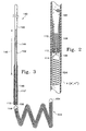
- FIg. 1 is a diagrammatic view of an electrolytic detachment system constructed according to the principles of the present invention.
- Fig. 2 is an enlarged partial section of the implant delivery assembly shown in Fig. 1, illustrating the interconnection among the guidewire, sacrificial link and implant.
- Fig. 3 illustrates a further embodiment of the interconnection shown in Fig. 2.
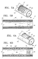
- Fig. 4 is an enlarged sectional view of the distal end portion of the catheter shown in Fig. 1 illustrating a return electrode arrangement according to the present invention.
- Fig. 4A shows another embodiment of the return electrode arrangement of Fig. 4.
- Figs. 5A and 5B show a further embodiment of the catheter of the present invention.
- Figs. 6A and 6B show yet another embodiment of the catheter of the present invention.
- FIGs. 7 and 8 schematically depict the method for deploying an occlusion device according to the present invention.
- Fig. 9 is a block diagram of a power drive delivery and detection circuit for detecting electrolytic separation of an occlusion device.
- Fig. 10 is a schematic representation of the block diagram of Fig. 9.
- system 2 generally comprises a delivery catheter 4 , which includes electrode 6 , an implant delivery assembly 8 and power supply 170 .
- Implant delivery assembly 8 generally includes a guidewire (or core wire), an implant and a sacrificial link that couples the implant to the guidewire, as will be described in more detail below.
- FIG. 2 an enlarged view of a portion of implant assembly 8 is shown illustrating the interconnection between the guidewire, sacrificial link and implant for facilitating electrolytic detachment of the implant from the guidewire.
- guidewire 102 tapers at its distal end to a point which is soldered into the proximal end of an implant 104 .
- implant 104 is shown as a vasoocclusive device, which in this case is a coil preferably of radiopaque physiologically compatible material such as platinum, tungsten, gold, iridium or alloys of these materials.
- Guidewire 102 which preferably is stainless steel, typically is approximately 10-30 mils in diameter and 50-300 cm in length from the entry site outside the body to sacrificial link 106 . As shown in Fig. 2 , sacrificial link 106 is the exposed portion of guidewire 102 that extends beyond insulator 112 . Link 106 is of a material, such as stainless steel, which is susceptible to electrolytic dissolution in blood.
- Guidewire 102 preferably is covered with an insulating material from its proximal end to its distal exposed portion which forms sacrificial link 106 .
- Suitable insulating materials include Teflon®, poluyrethane, polyethylene, polypropylene, or other suitable polymeric material.
- link 106 is not coated with an electrical insulator.
- the length of link 106 preferably is approximately equal to its diameter so that the electrolytic surface present after the vasoocclusive device is released is not substantially greater than would be a circle having the diameter of the link (link diameters, when dealing with aneurysms, may range from about 2-4 mils, for example). This configuration reduces the likelihood of multiple etch sites on the link.
- link 106 can be coated with a polymer, preferably parylene (polyxyxylene), and a UV laser (excimer type) used to cut a circumferential groove, having about a 1-3 mil in width, in the polymer to expose only a small ring of the link and localize the disintegration area.
- a polymer preferably parylene (polyxyxylene)
- a UV laser excimer type
- the groove is immediately adjacent to the interconnection between the link and implant.
- Implant delivery assembly 8 also includes insulators 110 and 112 and coil 108 , which is coupled at its proximal end to the guidewire by soldering, for example.
- Coil 108 is designed to provide some column strength to guidewire 102 while not detrimentally affecting the flexibility of the tapered portion of the guidewire. Obviously, in the area where support coil 108 is soldered to guidewire 102 , the coating on the guidewire is not present, allowing the solder to adhere to metal surfaces.
- Insulators 110 and 112 are provided at the distal end portion of guidewire 102 and serve to further remove stainless steel coil 108 from contact with the blood during electrolysis.
- insulators 110 and 112 comprise a sleeve and plug, respectively.
- end plug 112 and sleeve 110 are adhesively attached to each other to form an electrically insulating or electrolysis-tight housing about coil 108 .
- End plug 112 and sleeve 110 form a generally planar surface which is generally perpendicular to the axis of the guidewire 102 ( Fig. 2 ). The shape of the surface is not critical except to the extent it allows reasonably free access of the blood to sacrificial link 106 .
- guidewire 102 includes tapered or conical section 142 , section 144 which extends along a length of the guidewire designated with reference numeral 146 and section 148 . Section 144 gradually narrows down to thinner section 148 .
- Guidewire 102 is delivered to the desired site via a catheter constructed according to the present invention (e.g., catheter 4, 4' or 4'') and is typically 50-200 cm in length down to sacrificial link 106 .
- the distal section of guidewire 102 has an outer sleeve 110' , comprising Teflon® or other appropriate insulating material, which is longer than sleeve 110 in Fig. 2 .
- vasoocclusive device 104 when a coil, is prebiased to form a secondary loop or helix superimposed on its primary helical winding configuration when in a relaxed state, as shown in Fig. 3 .
- vasoocclusive device 104 preferably is extremely soft and its overall shape is easily deformed.
- vasoocclusive device 104 When inserted within a catheter, such as catheter 4 as diagrammatically shown in Fig. 2 , vasoocclusive device 104 is easily straightened to lie axially within the catheter. Once ejected from the tip of the catheter, vasoocclusive device 104 may form a shape such as that shown in Fig. 3 .
- device 104 may be constructed to have a different secondary shape or it may be loosely deformed to conform to the interior shape of the aneurysm.
- the distal end of vasoocclusive device 104 may also have an end plug or tip 154 to prevent punctures of endolumenal structures such as an aneurysm wall when introduced into an aneurysm sac.
- implant 104 is shown as a vasoocclusive coil, it may take other forms. It can be a vasoocclusive braid, for example. Vasoocclusive device 104 also may be covered or connected with fibrous materials tied to the outside of the coil or braided onto the outer cover of the coil as desired. Such fibrous adjuvants may be found in U.S. Patent Appl. No. 07/965,973, to Phelps et al , or in U.S. Patent Appl. No. 07/771,013, entitled "Vasoocclusion Coil with Attached Fibrous Elements", the entirety of which are incorporated by reference.
- Catheter 4 preferably comprises an elongated tubular member or tube having a laminate structure comprising a pair of concentrically arranged tubular members or tubes 10 and 12 .
- the inner surface or wall of tube 10 defines lumen 14 through which the implant delivery assembly 8 is passed.
- This construction facilitates positioning or embedding the electrode and conductor within the catheter as will be more fully appreciated from the description below.
- other catheter constructions may be used without departing from the scope of the invention.
- return electrode 6 is provided within catheter 4 .
- the electrode can, for example, comprise copper, platinum, nitinol or alloys thereof. It is important that electrode 6 be positioned within catheter 4 to minimize the risk of or avoid presenting an exposed surface that could interface with endolumenal structures in the electrolysis or detachment zone. In general, the electrode is arranged to minimize the likelihood of electrical contact with such endolumenal structures.
- electrode 6 preferably also is positioned or spaced longitudinally inward from the distal tip of catheter 4 , as shown in Fig. 4 , so that the possibility of any coils (previously delivered to the detachment or electrolysis zone) contacting the electrode and adversely affecting electrolysis is minimized or eliminated.
- the electrode preferably is as close as possible to the distal tip of the catheter to minimize the impedance in the return current path, the most distal surface of the electrode preferably is spaced inwardly from the distal end of the catheter a distance equal to at least one-half the inner radius of lumen 14 to minimize or eliminate interference with other coils as noted above.
- the electrode preferably is exposed only to the internal lumen of the catheter, and is as distal as possible without conducting at the catheter tip.
- the most exposed surface such as distal side surface 6a illustrated in the example shown in Fig. 4A, is electrically isolated.
- This arrangement also is believed to provide the desired results and can be accomplished, for example, by applying a coating or thin film 7 of insulation material to distal or transversely extending surface 6a of electrode 6 as would be apparent to one of ordinary skill in the art.
- the insulation also can be extended proximally along a portion of the inner circumferential surface of electrode 6 .
- the fluid (preferably a saline solution) flowing in the delivery catheter will provide a reproducible Impedance path from the internal electrode to the detachment zone where the sacrificial link resides and, thus, reduce detachment time variability.
- electrode 6 is annular and positioned inside outer tube 12 and adjacent to the distal end of inner tube 10 .
- the inner diameter of annular electrode 6 preferably is the same as the inner diameter of inner tube 10 so that the electrode and inner tube 10 present a continuous, nonobstructed, smooth surface to prevent implant or coil 104 from touching that surface when being delivered through lumen 14 to the target site.
- the annular configuration also advantageously provides a large exposed electrode surface that enhances current flow efficiencies. Although a particular electrode configuration has been shown, it should be understood that other configurations can be used. Generally, a large electrode surface area is desired as it increases current flow efficiencies by aiding too large a current density passing therethrough. For example, a segmented electrode can be used that is spaced in the circumferential direction along the inner surface of the catheter in the same position as shown in Figs. 4 or 4A .
- Catheter 4 is further provided with a conductor 16 .
- conductor 16 is in the form of wire and has a distal end that is coupled, for example by soldering, to electrode 6 at the general location indicated by reference numeral 18 .
- Conductor 16 extends from electrode 6 between tubular members 10 and 12 to proximal end portion of catheter 4 where it can be electrically connected to power supply 170 either directly or with a lead as would be apparent to one of ordinary skill.
- conductor 6 can extend through a radial portion of the proximal portion of catheter 4 adjacent to hub 20 as shown in Fig.
- conductor 6 can extend into a conventional hub assembly 20 (diagrammatically shown in Fig. 1 ) where the conductor 6 is electrically coupled to lead 22 via a connection in the hub.
- Delivery catheter 4 preferably is manufactured in the following way which is provided for illustrative purposes, but not intended to limit the invention.
- Inner tube 10 and electrode 6 are positioned on a mandrel having a diameter slightly less than the inner diameter of inner tube 10 and electrode 6 .
- Electrode 6 is positioned immediately adjacent the distal end of inner tube 10 , as shown in Fig. 4 .
- the conductor 16 is then coupled to the electrode and extended toward the proximal end portion of the catheter, where it eventually is interconnected with hub 20 , or extended radially through tube 12 adjacent to hub 20 as described above. Referring to Fig.
- outer tube 12 is then moved over the electrode toward the distal end of inner tube 10 and then toward the proximal portion of catheter 4 , where it is coupled to hub 20 .
- conductor or wire 16 is embedded in the catheter wall and prevented from entering lumen 14 , where it could otherwise interfere with the delivery of coil 104 .
- a filler 24 comprising thermoplastic material, for example, is provided to maintain an essentially constant lumen diameter and embed the distal side surface 6a of electrode 6 in the catheter to preclude its exposure to the endolumenal environment.
- catheter 4' is the same as catheter 4 except that the conductor, designated with reference numeral 16' , as a generally tubular braided member (e.g., having a construction like a "Chinese finger").
- Conductor 16' preferably is positioned between tubes 10 and 12 for the reasons discussed above.
- the braided construction allows the conductor to provide the catheter with variable stiffness simply by varying the mesh size of the braid along the length of the conductor.
- the mesh size of the braid progressively increases toward the distal end of the conductor so that the catheter flexibility progressively increases toward the distal tip. This allows the catheter to maneuver into very small, complex vessel structures.
- the coil is configured as a coil as shown in Figs. 6A and B and designated with reference character 16" .
- the coil pitch preferably increases toward the distal tip to progressively increase the flexibility of the catheter in the same direction to enhance catheter maneuverability as noted above.
- Coil 16" can be coupled to electrode 6 .
- the distal portion of coil 16" can be substituted for electrode 6 as shown in Fig. 6B . That is, in a preferred embodiment, coil portion 16" , which extends distally of tube 10, forms the electrode.
- Fig. 7 shows the placement of an occlusion device described above within an aneurysm.
- the procedure for placing an embolic device is typically practiced under fluoroscopic control with local anesthesia.
- a transfemoral catheter is utilized to treat a cerebral aneurysm and is usually introduced at the groin.
- the physician guides the distal tip of the catheter to the target site.
- the embolic device is then inserted into the catheter.
- Using a fluoroscope the physician guides the device to the desired position before separation is initiated.
- the vasoocclusive device 104 is platinum, it is not effected by electrolysis.
- the guidewire and pertinent portions of the supporting coils at the distal tip of the guidewire are adequately coated with insulating coverings, only the exposed portion at the sacrificial link 106 is effected by the electrolysis.
- catheter 4 is positioned in a vessel 156 with the tip of catheter 4 placed near neck 160 of aneurysm 162 .
- a vasoocclusive device such as device 104 , is fed into aneurysm 162 at least until sacrificial link 106 is exposed beyond the distal tip of the catheter 158 .
- the guidewire and catheter can be provided with radiopaque markers to facilitate observation of the relative positions of the guidewire and catheter distal ends as disclosed in U.S. Patent No. 5,354,295, which is hereby incorporated herein by reference.
- the catheter and guidewire may be provided with radiopaque markers, such as markers 164 and 166 , that are arranged so that they become aligned when sacrificial link 106 is just outside the distal tip of the catheter as diagrammitically shown in Fig. 7 .
- the positive terminal of power supply 170 is attached to the proximal end of guidewire 102 and, thus, to link 106 .
- Negative or return electrode 6 is coupled to the negative terminal of power supply 170 , as described above.
- a vasoocclusive device After a vasoocclusive device has been properly placed inside the aneurysm 162 , the power is delivered to link 106 and a solution, preferably a saline solution, is delivered through the catheter to enhance current flow from link 106 into catheter 4 to electrode 6 .
- a solution preferably a saline solution
- guidewire 102 After sacrificial link 106 is completely dissolved by electrolytic action, typically within 1-10 minutes, thereby detaching device 104 from guidewire 102 , guidewire 102 is removed from catheter 4 and from vessel 156 . Additional vasoocclusive devices may be placed in aneurysm 162 along with previously detached devices 104 until aneurysm 162 is occluded as shown in Fig. 8 . At this point, guidewire 102 and catheter 158 are withdrawn.
- a detachment detection system such as disclosed in PCT application number PCT/US95/02635 entitled “Endovascular Embolic Detachment Detection Method,” may be used with the invention to determine when the implant becomes detached so that the power supply can be shut down.
- DC power with AC superposition is provided to facilitate both electrolysis and detection.
- the DC power input facilitates electrolysis of link 106 and, thus, detachment of the coil, while the AC power provides a signal to monitor and detect detachment. More specifically, the voltage or current amplitude of the AC signal is monitored so that the DC power input can be interrupted in response to detecting a sudden change in the AC signal amplitude. If the DC power source is of a constant current design, the voltage amplitude of the AC signal would be monitored. If the DC source has a constant voltage output, the current amplitude of the AC signal provides the desired change.
- EDDC embolic device detection circuit
- a constant current drive circuit and feedback loop 310 and an EDDC 319 for inducing and detecting the electrolytic separation of an occlusion device from a delivery member or guidewire are shown.
- the EDDC includes an AC impedance monitoring circuit and a circuit for detecting changes in the monitored impedance which can comprise microprocessor 300 as will be described in more detail below.
- the power supply and detection circuit ( 310 , 319 ) provide a means to supply DC power with AC superposition and directly monitor the AC impedance by observing the reaction of amplifier 330 in response to the change in AC impedance.
- AC signal source 400 is coupled to the reference input of amplifier 330 so as to modulate the output current (i.e., provide AC superposition on the DC current).
- the output current i.e., provide AC superposition on the DC current.
- Capacitor 401 is provided between AC signal source 400 and amplifier 330 to isolate DC bias from the AC signal input.
- Reference Voltage 333 and current sense resistor 342 and amplifier 330 comprise a constant current drive circuit.
- One suitable amplifier is a TI2274N amplifier manufactured by Texas Instruments.
- an AC signal is provided to the non-inverting input of amplifier 330 where it is summed with the DC current reference.
- DC current with AC superposition is output from amplifier 330 and sent to the sacrificial link (e.g., link 106 shown in Fig. 2 ,) which is positioned in patient 200 .
- the DC and AC current paths branch.
- the DC current flows from the sacrificial link without passing through the coil, while the AC signal continues through the coil. These current paths rejoin at return electrode 6 ( TIM: Please Confirm ) and continue to AC and DC feedback loop 402 .
- the AC signal is monitored at the output of the constant current amplifier where a measurement of AC impedance can be made through EDDC 319 .
- the amplitude of the AC signal is monitored through pick-off capacitor 340 ( Fig. 10 ), in this case, a 0.1 microfarad monolithic capacitor.
- the AC signal from capacitor 340 is then amplified in the AC signal amplifier 320 , and is rectified and the peak detected in the AC to DC rectifier 321 .
- the DC signal, the level of which is representative of the amplitude of the AC voltage of constant current amplifier 330 is then sent to the microprocessor (CPU) 300 for monitoring and analysis as described below.
- the AC signal which in the illustrated embodiment described above is voltage, is monitored by sampling the level of the amplified DC signal every 10 to 250 milliseconds, preferably every 50 to 200 milliseconds, and constantly averaging the signal every 5 to 50 samples, preferably every 10-20 samples or every 0.5-10 seconds, preferably every 2-6 seconds. In this manner, the CPU can accurately determine the instant the occlusion device detaches as discussed below.
- constant current amplifier 330 instantly reacts to the change in AC impedance.
- the voltage amplitude of the AC waveform increases in an attempt to maintain the constant AC current set at the non-inverting input.
- the amplified EDDC signal will show a sudden voltage increase of greater than 20%, preferably an increase of greater than 30% of the average level for the procedure. This sudden voltage increase reliably detects the dissolution of the junction between the embolic device and the guidewire.
- the microprocessor When the sudden voltage decrease is detected, the microprocessor immediately halts current flow, and no further electrolysis can occur. Using fluoroscopy, the physician can verify that detachment has occurred. If detachment is incomplete and further electrolysis is necessary, the procedure can be resumed by pressing the current-select switch on the front panel. If detachment is verified, the physician can turn off the power supply and withdraw the guidewire. If necessary, another coil can be placed at the site and the power supply started again. If no action is taken, the power supply will automatically turn itself off after 15 minutes.
Abstract
Description
- The invention generally relates to the delivery of an occlusion device to a desired site in a mammal to facilitate the formation of mechanical blockage or thrombi in arteries, veins, aneurysms, vascular malformations, and arteriovenous fistulas. More specifically, the invention involves apparatus for facilitating electrolytic separation of an implant, such as an embolic device, from a delivery member.
- Approximately 25,000 intracranial aneurysms rupture each year in North America. The primary purpose of treatment for a ruptured intracranial aneurysm is to prevent rebleeding. There are a variety of ways to treat ruptured and non-ruptured aneurysms.
- Possibly the most widely known of these procedures is an extravascular approach which involves surgery or microsurgery. This treatment is common with intracranial berry aneurysms. The method comprises clipping the neck of the aneurysm, performing a suture ligation of the neck, or wrapping the entire aneurysm. Each of these procedures is formed by intrusive invasion into the body and performed from the outside of the aneurysm or target site. General anesthesia, craniotomy, brain retraction, and placement of a clip around the neck of the aneurysm are typically required in these surgical procedures. The surgical procedure is often delayed while waiting for the patient to stabilize medically. For this reason, many patients die from the underlying disease or defect prior to the initiation of the procedure.
- Another procedure is the extra-intravascular approach. This approach involves surgically exposing or stereotactically reaching an aneurysm with a probe. The wall of the aneurysm is then perforated from the outside and various techniques are used to occlude the interior in order to prevent it from rebleeding. The techniques used to occlude the aneurysm include electrothrombosis, adhesive embolization, hog hair embolization, and ferromagnetic thrombosis. These procedures are discussed in U.S. Patent No. 5,122,136 to Guglielmi et al., the entirety of which is incorporated herein by reference.
- A still further approach, the least invasive, also is described in Guglielmi et al (supra). It is the endovascular approach. In this approach, the interior of the aneurysm is entered by use of a catheter such as those shown in Engelson (Catheter Guidewire), U.S. Patent No. 4,884,575 and also in Engelson (Catheter for Guidewire Tracking), U.S. Patent No. 4,739,768. These patents describe devices utilizing guidewires and catheters which allow access to an aneurysm from remote portions of the body. Specifically, by the use of catheters having very flexible distal regions and guidewires which are steerable to the region of the aneurysm, embolic devices which may be delivered through the catheter are an alternative to the extravascular and extra-intravascular approaches.
- The endovascular approach typically includes two major steps. The first step involves the introduction of the catheter to the aneurysm site using devices such as shown in the Engelson patents. The second step often involves filling the aneurysm in some fashion or another. For instance, a balloon may be introduced into the aneurysm from the distal portion of the catheter where it is inflated, detached, and left to occlude the aneurysm. In this way, the parent artery is preserved. Balloons are becoming less in favor because of difficulty in introducing the balloon into the aneurysm sac, the possibility of an aneurysm rupture due to overinflation of the balloon within the aneurysm or due to stress placed on the nonspherically shaped aneurysm by the spherical balloon, and the risk associated with traction produced when detaching the balloon.
- A highly desirable embolism-forming device that ray be introduced into an aneurysm using endovascular placement procedures, is found in U.S. Patent No. 1,994,069, to Ritchart et al. The device, typically a platinum/tungsten alloy coil having a very small diameter, may be introduced into an aneurysm through a catheter such as those described in Engelson above. These coils are often made of wire having a diameter of 2-6 mils. The coil diameter may be 10-30 mils. These soft, flexible coils may be of any length desirable and appropriate for the site to be occluded. For instance, the coils may be used to fill a berry aneurysm. Within a short period of time after the filling of the aneurysm with the embolic device, a thrombus forms in the aneurysm and is shortly thereafter complemented with a collagenous material which significantly lessens the potential for aneurysm rupture.
- Coils such as seen in Ritchart et al. may be delivered to the vasculature site in a variety of ways including, e.g., mechanically detaching them from the delivery device as is shown in U.S. Patent No. 5,250,071, to Palermo or by electrolytic detachment as is shown in Guglielmi et al. (U.S. Patent No. 5,122,136), discussed above.
- Guglielmi et al. shows an embolism-forming device and procedure for using that device. Specifically, the Guglielmi device fills a vascular cavity (such as an aneurysm) with an embolic device, typically a platinum coil, that has been endovascularly delivered. The coil is then severed from its insertion tool by the application of a small electric current. Desirably, the insertion device involves a guidewire which is attached at its distal end to the embolic device by a sacrificial joint that is electrolytically dissolvable. Guglielmi et al. suggests that when the embolic device is a platinum coil, the platinum coil may be 1.50 cm. or longer as is necessary. Proximal of the embolic coil is a guidewire, often stainless steel in construction. The guidewire is used to push the platinum embolic coil, obviously with great gentleness, into the vascular site to be occluded. The patent shows a variety of ways of linking the embolic coil to the pusher guidewire. For instance, the guidewire is tapered at its distal end and the distal tip of the guidewire is soldered into the proximal end of the embolic coil. Additionally, a stainless steel coil is wrapped coaxially about the distal tapered portion of the guidewire to provide column strength to the guidewire. This coaxial stainless steel wire is joined both to the guidewire and to the embolic coil. Insulation may be used to cover a portion of the strength-providing stainless steel coil. This arrangement provides for two regions which must be electrolytically severed before the embolic coil is severed from the guidewire.
- U.S. Patent application 08/147,529 filed November 3, 1993, describes a variation of the Guglielmi detachable coil using an improved sacrificial link between the guidewire and the coil. The size of the sacrificial link is limited to allow more precise placement of the embolic device and facilitate quick detachment. The focussed electrolysis found at the sacrificial site reduces the overall possibility of occurrence of multiple electrolysis sites and liberation of large particles from those sites.
- The circuit involved in the electrolytic coil detachment arrangements discussed above generally includes a power source having its positive terminal coupled to the sacrificial link via a guidewire, for example. More specifically, a positive electric current of approximately 0.01 to 2 milliamps is applied to the guidewire which is coupled to the sacrificial link that is intended to undergo electrolytic disintegration and which initially couples the implant (e.g., the vasoocclusion device) to the guidewire. The negative terminal of the power source is typically coupled to an electrode that is placed over and in contact with the patient's skin. This can be accomplished, for example, with a large skin electrode such as a ground pad or needle. Thus, the current path flowing from the detachment zone (etch site on the sacrificial link) to the ground electrode includes the patient's fluids and tissues. While the impedance to current flow is generally predictable through the delivery member or guidewire (approximately 200 ohms), the additional impedance of the current's return path to the ground electrode is dependent on variable impedances which depend on the blood milieu of the aneurysm, density of coil packing in the aneurysm, conductivity of the aneurysm wall, patient's tissue and return skin electrode, and fluid volume, for example. If, due to the variable Impedances, the impedance to current flow through the occlusive device, which preferably is a platinum coil, becomes less than the impedance to current flow from the detachment zone, it is believed that detachment times will increase.
- Another return electrode or cathode arrangement is disclosed in U.S. Patent No. 5,364,295 to Guglielmi et al. In that arrangement, the microcatheter is supplied with an end electrode. More specifically, the electrode extends distally from the microcatheter and is coupled to an electrical conductor or wire disposed along the length of the microcatheter. The wire is ultimately led back to the negative terminal of the power source so that the electrode (ring electrode) is used as the cathode during electrothrombosis instead of an exterior skin electrode.
- According to the '295 patent, the electrical currents and electrical current paths which are set up during electrothrombosis formation using the above-described catheter-electrode arrangement are local to the site of application, which allows even smaller currents and voltages to be used to initiate electrothrombosis than in the situation when an exterior skin electrode must be utilized. The electrothrombosic current distributions are also better controlled and localized to the site of the thrombus formation. The possibility of stray thrombus formations occurring at unwanted sites or uncontrolled and possibly unwanted electrical current patterns being established elsewhere in the brain or body is therefore largely avoided.
- However, Applicant has found that under certain conditions, this return electrode arrangement may not provide consistent results. For example, since the return electrode or cathode extends distally from the microcatheter and is directly exposed to the endolumenal environment, it can contact tissue in that environment, such as the wall of the aneurysm. It is believed that such contact would increase the resistance in the current return path from the sacrificial link to the return electrode and increase electrolytic detachment times. In addition, multiple coils typically are placed in the aneurysm to increase the packing density therein and enhance thrombosis. Coils previously placed within the aneurysm may contact the electrode as the microcatheter is positioned at the aneurysm opening to deliver a further coil. It is believed that this may result in the current finding a lower impedance return path through portions of contacting coils than through the blood or fluid between the sacrificial link and the electrode. This may preclude the necessary electrolysis for disintegration of the sacrificial link, since optimal electrolysis occurs when the fluid resistance is less than the coil resistance.
- The present invention involves a catheter for introducing a delivery member such as a guidewire having an implant coupled thereto via an electrolytically disintegratable link that is coupled to the anode of a power supply having an anode and a cathode. According to the invention, the catheter comprises an elongated tubular member having an outer surface, proximal and distal end portions, a lumen extending between those portions, an electrode and a conductor. The electrode is disposed within the outer surface of the tubular member in the vicinity of the distal end portion and has a surface that faces and communicates with the lumen. The electrode is electrically coupled to the conductor which, in turn, is adapted for coupling to the power supply cathode such that when the electrolytically disintegratable link is placed in an electrolytic solution, such as can be found in an aneurysm, and positive current is provided from the power supply to the link, current from the link may return to the cathode of the power supply via the electrode. With this construction, the electrode is shielded from endolumenal structures which could otherwise increase the resistance in the current path from the sacrificial link to the electrode. The positioning of the electrode in the catheter as described above allows a reproducible impedance path from the electrode to the detachment zone, thus reducing detachment time variability.
- In one embodiment, the electrode also is spaced inwardly from the distal tip of the catheter. This advantageously minimizes or eliminates the possibility of implants, such as occlusion devices, previously placed at the site, from contacting the electrode and creating a current return path that bypasses the blood or fluid between the etch site on the sacrificial link and the return electrode. Such contact may otherwise preclude electrolysis and coil detachment. The distal most surface of the electrode also may be electrically insulated to minimize the likelihood of endolumenal structures from contacting the electrode.
- According to another embodiment of the invention, the most distal surface of the electrode may be adjacent to the distal tip of the catheter. In this arrangement, that most distal surface is electrically insulated to minimize the likelihood of endolumenal structures contacting the electrode.
- According to another aspect of the invention, the conductor is embedded in the wall of the tubular member. This advantageously places the conductor or lead outside the lumen so that it does not interfere with the passage of the implant (e.g., an occlusion device such as an embolic coil) as the implant is delivered through the catheter to the desired site. This arrangement also provents the conductor from contacting the vessel wall.
- According to a further feature of the invention, the electrode is positioned so as not to extend radially inward beyond the inner surface of the tubular member that defines the lumen. With this construction, the possibility of the electrode catching the implant or occlusion device as it passes the electrode is largely avoided or eliminated.
- The above is a brief description of some of the features and advantages of the present invention. Other features, advantages and embodiments of the invention will be apparent to those skilled in the art from the following description, accompanying drawings and appended claims.
- FIg. 1 is a diagrammatic view of an electrolytic detachment system constructed according to the principles of the present invention.
- Fig. 2 is an enlarged partial section of the implant delivery assembly shown in Fig. 1, illustrating the interconnection among the guidewire, sacrificial link and implant.
- Fig. 3 illustrates a further embodiment of the interconnection shown in Fig. 2.
- Fig. 4 is an enlarged sectional view of the distal end portion of the catheter shown in Fig. 1 illustrating a return electrode arrangement according to the present invention.
- Fig. 4A shows another embodiment of the return electrode arrangement of Fig. 4.
- Figs. 5A and 5B show a further embodiment of the catheter of the present invention.
- Figs. 6A and 6B show yet another embodiment of the catheter of the present invention.
- Figs. 7 and 8 schematically depict the method for deploying an occlusion device according to the present invention.
- Fig. 9 is a block diagram of a power drive delivery and detection circuit for detecting electrolytic separation of an occlusion device.
- Fig. 10 is a schematic representation of the block diagram of Fig. 9.
- Referring to the drawings in detail wherein like numerals indicate like elements, an implant delivery and
electrolytic detachment system 2 constructed according to the principles of the present invention is diagrammatically shown. Referring to Fig. 1,system 2 generally comprises adelivery catheter 4, which includeselectrode 6, animplant delivery assembly 8 andpower supply 170.Implant delivery assembly 8 generally includes a guidewire (or core wire), an implant and a sacrificial link that couples the implant to the guidewire, as will be described in more detail below. - Referring to Fig. 2, an enlarged view of a portion of
implant assembly 8 is shown illustrating the interconnection between the guidewire, sacrificial link and implant for facilitating electrolytic detachment of the implant from the guidewire. Specifically, guidewire 102 tapers at its distal end to a point which is soldered into the proximal end of animplant 104. In the illustrative embodiment,implant 104 is shown as a vasoocclusive device, which in this case is a coil preferably of radiopaque physiologically compatible material such as platinum, tungsten, gold, iridium or alloys of these materials. -
Guidewire 102, which preferably is stainless steel, typically is approximately 10-30 mils in diameter and 50-300 cm in length from the entry site outside the body tosacrificial link 106. As shown in Fig. 2,sacrificial link 106 is the exposed portion ofguidewire 102 that extends beyondinsulator 112.Link 106 is of a material, such as stainless steel, which is susceptible to electrolytic dissolution in blood. -
Guidewire 102 preferably is covered with an insulating material from its proximal end to its distal exposed portion which formssacrificial link 106. Suitable insulating materials include Teflon®, poluyrethane, polyethylene, polypropylene, or other suitable polymeric material. In a first embodiment, link 106 is not coated with an electrical insulator. In this case, the length oflink 106 preferably is approximately equal to its diameter so that the electrolytic surface present after the vasoocclusive device is released is not substantially greater than would be a circle having the diameter of the link (link diameters, when dealing with aneurysms, may range from about 2-4 mils, for example). This configuration reduces the likelihood of multiple etch sites on the link. Alternatively, link 106 can be coated with a polymer, preferably parylene (polyxyxylene), and a UV laser (excimer type) used to cut a circumferential groove, having about a 1-3 mil in width, in the polymer to expose only a small ring of the link and localize the disintegration area. Preferably, the groove is immediately adjacent to the interconnection between the link and implant. -
Implant delivery assembly 8 also includesinsulators coil 108, which is coupled at its proximal end to the guidewire by soldering, for example.Coil 108 is designed to provide some column strength to guidewire 102 while not detrimentally affecting the flexibility of the tapered portion of the guidewire. Obviously, in the area wheresupport coil 108 is soldered toguidewire 102, the coating on the guidewire is not present, allowing the solder to adhere to metal surfaces. -
Insulators guidewire 102 and serve to further removestainless steel coil 108 from contact with the blood during electrolysis. In the illustrative embodiment,insulators end plug 112 andsleeve 110 are adhesively attached to each other to form an electrically insulating or electrolysis-tight housing aboutcoil 108.End plug 112 andsleeve 110 form a generally planar surface which is generally perpendicular to the axis of the guidewire 102 (Fig. 2). The shape of the surface is not critical except to the extent it allows reasonably free access of the blood tosacrificial link 106. Curved, slotted and other variations of the end surface are also contemplated to be used in this invention. As noted above, the distal end ofguidewire 102 is inserted into the solder joint 114 forming the proximal end ofvasoocclusive device 104. - Referring to Fig. 3, one suitable configuration for
guidewire 102 is shown. In this embodiment, guidewire 102 includes tapered orconical section 142,section 144 which extends along a length of the guidewire designated withreference numeral 146 andsection 148.Section 144 gradually narrows down tothinner section 148.Guidewire 102 is delivered to the desired site via a catheter constructed according to the present invention (e.g.,catheter 4, 4' or 4'') and is typically 50-200 cm in length down tosacrificial link 106. In the arrangement shown in Fig. 3, the distal section ofguidewire 102 has an outer sleeve 110', comprising Teflon® or other appropriate insulating material, which is longer thansleeve 110 in Fig. 2. - Preferably,
vasoocclusive device 104, when a coil, is prebiased to form a secondary loop or helix superimposed on its primary helical winding configuration when in a relaxed state, as shown in Fig. 3. However,vasoocclusive device 104 preferably is extremely soft and its overall shape is easily deformed. When inserted within a catheter, such ascatheter 4 as diagrammatically shown in Fig. 2,vasoocclusive device 104 is easily straightened to lie axially within the catheter. Once ejected from the tip of the catheter,vasoocclusive device 104 may form a shape such as that shown in Fig. 3. Alternatively,device 104 may be constructed to have a different secondary shape or it may be loosely deformed to conform to the interior shape of the aneurysm. The distal end ofvasoocclusive device 104 may also have an end plug ortip 154 to prevent punctures of endolumenal structures such as an aneurysm wall when introduced into an aneurysm sac. - Although
implant 104 is shown as a vasoocclusive coil, it may take other forms. It can be a vasoocclusive braid, for example.Vasoocclusive device 104 also may be covered or connected with fibrous materials tied to the outside of the coil or braided onto the outer cover of the coil as desired. Such fibrous adjuvants may be found in U.S. Patent Appl. No. 07/965,973, to Phelps et al, or in U.S. Patent Appl. No. 07/771,013, entitled "Vasoocclusion Coil with Attached Fibrous Elements", the entirety of which are incorporated by reference. - Referring to Fig. 4, a sectional view of
delivery catheter 4 is shown in accordance with the present invention.Catheter 4 preferably comprises an elongated tubular member or tube having a laminate structure comprising a pair of concentrically arranged tubular members ortubes tube 10 defineslumen 14 through which theimplant delivery assembly 8 is passed. This construction facilitates positioning or embedding the electrode and conductor within the catheter as will be more fully appreciated from the description below. However, other catheter constructions may be used without departing from the scope of the invention. - In accordance with the present invention, return
electrode 6 is provided withincatheter 4. The electrode can, for example, comprise copper, platinum, nitinol or alloys thereof. It is important thatelectrode 6 be positioned withincatheter 4 to minimize the risk of or avoid presenting an exposed surface that could interface with endolumenal structures in the electrolysis or detachment zone. In general, the electrode is arranged to minimize the likelihood of electrical contact with such endolumenal structures. - According to one embodiment of the invention,
electrode 6 preferably also is positioned or spaced longitudinally inward from the distal tip ofcatheter 4, as shown in Fig. 4, so that the possibility of any coils (previously delivered to the detachment or electrolysis zone) contacting the electrode and adversely affecting electrolysis is minimized or eliminated. Although the electrode preferably is as close as possible to the distal tip of the catheter to minimize the impedance in the return current path, the most distal surface of the electrode preferably is spaced inwardly from the distal end of the catheter a distance equal to at least one-half the inner radius oflumen 14 to minimize or eliminate interference with other coils as noted above. In other words, the electrode preferably is exposed only to the internal lumen of the catheter, and is as distal as possible without conducting at the catheter tip. - According to another embodiment of the invention, the most exposed surface, such as
distal side surface 6a illustrated in the example shown in Fig. 4A, is electrically isolated. This arrangement also is believed to provide the desired results and can be accomplished, for example, by applying a coating orthin film 7 of insulation material to distal or transversely extendingsurface 6a ofelectrode 6 as would be apparent to one of ordinary skill in the art. The insulation also can be extended proximally along a portion of the inner circumferential surface ofelectrode 6. - With the above-described electrode positioning, the fluid (preferably a saline solution) flowing in the delivery catheter will provide a reproducible Impedance path from the internal electrode to the detachment zone where the sacrificial link resides and, thus, reduce detachment time variability.
- In the illustrative embodiment,
electrode 6 is annular and positioned insideouter tube 12 and adjacent to the distal end ofinner tube 10. The inner diameter ofannular electrode 6 preferably is the same as the inner diameter ofinner tube 10 so that the electrode andinner tube 10 present a continuous, nonobstructed, smooth surface to prevent implant orcoil 104 from touching that surface when being delivered throughlumen 14 to the target site. The annular configuration also advantageously provides a large exposed electrode surface that enhances current flow efficiencies. Although a particular electrode configuration has been shown, it should be understood that other configurations can be used. Generally, a large electrode surface area is desired as it increases current flow efficiencies by aiding too large a current density passing therethrough. For example, a segmented electrode can be used that is spaced in the circumferential direction along the inner surface of the catheter in the same position as shown in Figs. 4 or 4A. -
Catheter 4 is further provided with aconductor 16. Referring to Fig. 4,conductor 16 is in the form of wire and has a distal end that is coupled, for example by soldering, toelectrode 6 at the general location indicated byreference numeral 18.Conductor 16 extends fromelectrode 6 betweentubular members catheter 4 where it can be electrically connected topower supply 170 either directly or with a lead as would be apparent to one of ordinary skill. For example,conductor 6 can extend through a radial portion of the proximal portion ofcatheter 4 adjacent tohub 20 as shown in Fig. 1 and then be coupled to lead 22 (e.g., at reference point 26) which is electrically coupled to the negative terminal or cathode of the power supply. Alternatively,conductor 6 can extend into a conventional hub assembly 20 (diagrammatically shown in Fig. 1) where theconductor 6 is electrically coupled to lead 22 via a connection in the hub. -
Delivery catheter 4 preferably is manufactured in the following way which is provided for illustrative purposes, but not intended to limit the invention.Inner tube 10 andelectrode 6 are positioned on a mandrel having a diameter slightly less than the inner diameter ofinner tube 10 andelectrode 6.Electrode 6 is positioned immediately adjacent the distal end ofinner tube 10, as shown in Fig. 4. Theconductor 16 is then coupled to the electrode and extended toward the proximal end portion of the catheter, where it eventually is interconnected withhub 20, or extended radially throughtube 12 adjacent tohub 20 as described above. Referring to Fig. 4,outer tube 12 is then moved over the electrode toward the distal end ofinner tube 10 and then toward the proximal portion ofcatheter 4, where it is coupled tohub 20. In this manner, conductor orwire 16 is embedded in the catheter wall and prevented from enteringlumen 14, where it could otherwise interfere with the delivery ofcoil 104. At the very distal end of the catheter, afiller 24 comprising thermoplastic material, for example, is provided to maintain an essentially constant lumen diameter and embed thedistal side surface 6a ofelectrode 6 in the catheter to preclude its exposure to the endolumenal environment. - Referring to Figs. 5A and 5B, a further embodiment of the invention is shown. In this embodiment, catheter 4' is the same as
catheter 4 except that the conductor, designated with reference numeral 16', as a generally tubular braided member (e.g., having a construction like a "Chinese finger"). Conductor 16' preferably is positioned betweentubes - In another embodiment of the invention, the coil is configured as a coil as shown in Figs. 6A and B and designated with
reference character 16". In this embodiment, the coil pitch preferably increases toward the distal tip to progressively increase the flexibility of the catheter in the same direction to enhance catheter maneuverability as noted above.Coil 16" can be coupled toelectrode 6. Alternatively, the distal portion ofcoil 16" can be substituted forelectrode 6 as shown in Fig. 6B. That is, in a preferred embodiment,coil portion 16", which extends distally oftube 10, forms the electrode. - Fig. 7 shows the placement of an occlusion device described above within an aneurysm. The procedure for placing an embolic device is typically practiced under fluoroscopic control with local anesthesia. A transfemoral catheter is utilized to treat a cerebral aneurysm and is usually introduced at the groin. The physician guides the distal tip of the catheter to the target site. The embolic device is then inserted into the catheter. Using a fluoroscope, the physician guides the device to the desired position before separation is initiated. When the
vasoocclusive device 104 is platinum, it is not effected by electrolysis. When the guidewire and pertinent portions of the supporting coils at the distal tip of the guidewire are adequately coated with insulating coverings, only the exposed portion at thesacrificial link 106 is effected by the electrolysis. - Returning to Fig. 7,
catheter 4 is positioned in avessel 156 with the tip ofcatheter 4 placed nearneck 160 ofaneurysm 162. A vasoocclusive device, such asdevice 104, is fed intoaneurysm 162 at least untilsacrificial link 106 is exposed beyond the distal tip of the catheter 158. The guidewire and catheter can be provided with radiopaque markers to facilitate observation of the relative positions of the guidewire and catheter distal ends as disclosed in U.S. Patent No. 5,354,295, which is hereby incorporated herein by reference. Alternatively, the catheter and guidewire may be provided with radiopaque markers, such asmarkers sacrificial link 106 is just outside the distal tip of the catheter as diagrammitically shown in Fig. 7. - A positive electric current of approximately 0.1-10 milliamps, preferably about 1 milliamp, at 0.1-6 volts, is applied to guidewire 102 (shown in dashed line) via
DC power supply 170 to form a thrombus withinaneurysm 162 and dissolvesacrificial link 106. As shown in Figs. 5 and 6, the positive terminal ofpower supply 170 is attached to the proximal end ofguidewire 102 and, thus, to link 106. Negative or returnelectrode 6 is coupled to the negative terminal ofpower supply 170, as described above. - After a vasoocclusive device has been properly placed inside the
aneurysm 162, the power is delivered to link 106 and a solution, preferably a saline solution, is delivered through the catheter to enhance current flow fromlink 106 intocatheter 4 toelectrode 6. Aftersacrificial link 106 is completely dissolved by electrolytic action, typically within 1-10 minutes, thereby detachingdevice 104 fromguidewire 102, guidewire 102 is removed fromcatheter 4 and fromvessel 156. Additional vasoocclusive devices may be placed inaneurysm 162 along with previously detacheddevices 104 untilaneurysm 162 is occluded as shown in Fig. 8. At this point, guidewire 102 and catheter 158 are withdrawn. - A detachment detection system, such as disclosed in PCT application number PCT/US95/02635 entitled "Endovascular Embolic Detachment Detection Method," may be used with the invention to determine when the implant becomes detached so that the power supply can be shut down. In general, DC power with AC superposition is provided to facilitate both electrolysis and detection.
- The DC power input facilitates electrolysis of
link 106 and, thus, detachment of the coil, while the AC power provides a signal to monitor and detect detachment. More specifically, the voltage or current amplitude of the AC signal is monitored so that the DC power input can be interrupted in response to detecting a sudden change in the AC signal amplitude. If the DC power source is of a constant current design, the voltage amplitude of the AC signal would be monitored. If the DC source has a constant voltage output, the current amplitude of the AC signal provides the desired change. A preferred power supply and embolic device detection circuit (EDDC) is described below. - Referring to Fig. 9, a constant current drive circuit and
feedback loop 310 and anEDDC 319 for inducing and detecting the electrolytic separation of an occlusion device from a delivery member or guidewire are shown. The EDDC includes an AC impedance monitoring circuit and a circuit for detecting changes in the monitored impedance which can comprisemicroprocessor 300 as will be described in more detail below. The power supply and detection circuit (310, 319) provide a means to supply DC power with AC superposition and directly monitor the AC impedance by observing the reaction ofamplifier 330 in response to the change in AC impedance. - Referring to Fig. 10,
AC signal source 400 is coupled to the reference input ofamplifier 330 so as to modulate the output current (i.e., provide AC superposition on the DC current). For purposes of example, a 31.25 kHz 100 mV peak-to-peak sine wave has been found to be a suitable input to the amplifier.Capacitor 401 is provided betweenAC signal source 400 andamplifier 330 to isolate DC bias from the AC signal input.Reference Voltage 333 andcurrent sense resistor 342 andamplifier 330 comprise a constant current drive circuit. One suitable amplifier is a TI2274N amplifier manufactured by Texas Instruments. - In operation, an AC signal is provided to the non-inverting input of
amplifier 330 where it is summed with the DC current reference. DC current with AC superposition is output fromamplifier 330 and sent to the sacrificial link (e.g., link 106 shown in Fig. 2,) which is positioned inpatient 200. The DC and AC current paths branch. The DC current flows from the sacrificial link without passing through the coil, while the AC signal continues through the coil. These current paths rejoin at return electrode 6 (TIM: Please Confirm) and continue to AC andDC feedback loop 402. The AC signal is monitored at the output of the constant current amplifier where a measurement of AC impedance can be made throughEDDC 319. - The amplitude of the AC signal is monitored through pick-off capacitor 340 (Fig. 10), in this case, a 0.1 microfarad monolithic capacitor. The AC signal from
capacitor 340 is then amplified in theAC signal amplifier 320, and is rectified and the peak detected in the AC toDC rectifier 321. The DC signal, the level of which is representative of the amplitude of the AC voltage of constantcurrent amplifier 330 is then sent to the microprocessor (CPU) 300 for monitoring and analysis as described below. - The AC signal, which in the illustrated embodiment described above is voltage, is monitored by sampling the level of the amplified DC signal every 10 to 250 milliseconds, preferably every 50 to 200 milliseconds, and constantly averaging the signal every 5 to 50 samples, preferably every 10-20 samples or every 0.5-10 seconds, preferably every 2-6 seconds. In this manner, the CPU can accurately determine the instant the occlusion device detaches as discussed below.
- When the occlusion device detaches, constant
current amplifier 330 instantly reacts to the change in AC impedance. The voltage amplitude of the AC waveform increases in an attempt to maintain the constant AC current set at the non-inverting input. During this period the amplified EDDC signal will show a sudden voltage increase of greater than 20%, preferably an increase of greater than 30% of the average level for the procedure. This sudden voltage increase reliably detects the dissolution of the junction between the embolic device and the guidewire. - When the sudden voltage decrease is detected, the microprocessor immediately halts current flow, and no further electrolysis can occur. Using fluoroscopy, the physician can verify that detachment has occurred. If detachment is incomplete and further electrolysis is necessary, the procedure can be resumed by pressing the current-select switch on the front panel. If detachment is verified, the physician can turn off the power supply and withdraw the guidewire. If necessary, another coil can be placed at the site and the power supply started again. If no action is taken, the power supply will automatically turn itself off after 15 minutes.
- Throughout this application, various publications, patents and patent applications are referred to by an identifying citation. The disclosures of these publications, patents and published patent applications are hereby incorporated by reference into this application.
- The above is a detailed description of particular embodiments of the invention. It is recognized that departures from the disclosed embodiment may be made within the scope of the invention and that many alterations and modifications may be made by those having ordinary skill in the art without departing from the spirit and scope of the invention set out in the claims. The full scope of the invention is set out in the claims that follow and their equivalents.
Claims (19)
- A catheter for introducing a guidewire having an implant coupled thereto via an electrolytically disintegratable link that is coupled to the anode of a power supply having an anode and a cathode, said catheter comprising:an elongated tubular member having an outer surface, proximal and distal end portions and an inner surface defining a lumen;an electrode disposed within said outer surface of said elongated tubular member in the vicinity of said distal end portion and having a surface that faces and communicates with said lumen; anda conductor electrically coupled to said electrode and adapted for coupling to the cathode of said power supply such that when said electrolytically disintegratable link is placed in an electrolytic solution and positive current from the power supply is provided to said link, current from said link may return to the cathode of said power supply via said electrode.
- The catheter of claim 1, wherein said distal end portion of said elongated tubular member includes a distal tip, said electrode being spaced inwardly from said distal tip.
- The catheter of claim 2, wherein said electrode is spaced inwardly from said distal tip a distance of at least one-half the radius of the lumen measured at said distal tip.
- The catheter of any one of the preceding claims, wherein said electrode is ring shaped.
- The catheter of any one of the preceding claims, wherein said electrode comprises metal.
- The catheter of any one of the preceding claims, wherein said conductor is embedded in said elongated tubular member.
- The catheter of any one of the preceding claims, wherein said conductor is in the form of a wire.
- The catheter of any one of claims 1 to 6, wherein said conductor comprises a tubular braided member.
- The catheter of claim 8, wherein said tubular braided member has an end portion generally aligned with said distal end portion of said elongated tube, said braided member end portion having a mesh size that is greater than at least a substantial extent of the remaining portion of said braided member.
- The catheter of claim 8 or claim 9, wherein said tubular braided member has multiple flexibilities along its length with the distal end portion of said braid having a relatively high flexibility.
- The catheter of any one of the preceding claims, wherein said conductor comprises a coil.
- The catheter of claim 11, wherein said coil has a varying pitch and the pitch and the distal end portion of the coil being relatively large.
- A catheter apparatus comprising:a power supply having an anode and cathode;an elongated tubular member having an outer surface, a proximal and distal end, and an inner surface defining a lumen; andan electrode disposed in said catheter radially inward from said outer surface and in the vicinity of said distal end, said electrode having a surface that faces and communicates with said lumen and is electrically coupled to said cathode.
- A mammalian implant delivery system comprising:a power supply having an anode and cathode;a catheter comprising a tubular member having an outer surface, a proximal and distal end, and an inner surface defining a lumen;an electrode disposed in said catheter radially inward from said outer surface and having a surface that faces and communicates with said lumen;a conductor having a first portion electrically coupled to said electrode and a second portion electrically coupled to said cathode;an implant suitable for mammalian implantation;a delivery member disposed in said catheter for delivering the implant to a region in the mammal; andan electrolytically disintegratable link coupling said delivery member to said implant, said link being electrically coupled to said anode.
- The apparatus or system of claim 13 or claim 14, wherein said electrode is spaced longitudinally inward from said distal end.
- The apparatus or system of any one of claims 13 to 15, further including a conductor that is embedded in said tubular member, said conductor having a first portion electrically coupled to said electrode and a second portion electrically coupled to said cathode.
- The catheter, apparatus or system of any one of the preceding claims, wherein said electrode has a most distal surface, said most distal surface being electrically insulated.
- The catheter, apparatus or system of any one of the preceding claims, wherein said elongated tubular member comprises a laminate construction including first and second tubes, said conductor being disposed between said first and second tubes.
- The catheter, apparatus or system of any one of the preceding claims, wherein said elongated tubular member does not extend radially inward beyond said inner surface.
Applications Claiming Priority (4)
| Application Number | Priority Date | Filing Date | Title |
|---|---|---|---|
| US43074495A | 1995-04-28 | 1995-04-28 | |
| US430744 | 1995-04-28 | ||
| US546516 | 1995-10-20 | ||
| US08/546,516 US6059779A (en) | 1995-04-28 | 1995-10-20 | Delivery catheter for electrolytically detachable implant |
Publications (3)
| Publication Number | Publication Date |
|---|---|
| EP0739607A2 true EP0739607A2 (en) | 1996-10-30 |
| EP0739607A3 EP0739607A3 (en) | 1997-08-06 |
| EP0739607B1 EP0739607B1 (en) | 2002-09-11 |
Family
ID=27028729
Family Applications (1)
| Application Number | Title | Priority Date | Filing Date |
|---|---|---|---|
| EP96302967A Expired - Lifetime EP0739607B1 (en) | 1995-04-28 | 1996-04-26 | Delivery catheter for electrolytically detachable implant |
Country Status (9)
| Country | Link |
|---|---|
| US (1) | US6059779A (en) |
| EP (1) | EP0739607B1 (en) |
| JP (1) | JP2874850B2 (en) |
| KR (1) | KR960037020A (en) |
| AT (1) | ATE223680T1 (en) |
| AU (1) | AU697100B2 (en) |
| CA (1) | CA2175100C (en) |
| DE (1) | DE69623524T2 (en) |
| ES (1) | ES2182948T3 (en) |
Cited By (15)
| Publication number | Priority date | Publication date | Assignee | Title |
|---|---|---|---|---|
| WO1999042038A1 (en) * | 1998-02-18 | 1999-08-26 | Boston Scientific Limited | Vaso-occlusive member assembly with multiple detaching points |
| EP0941700A1 (en) * | 1998-03-10 | 1999-09-15 | Cordis Corporation | Hydraulically detachable embolic coil assembly |
| EP0948935A1 (en) * | 1997-10-30 | 1999-10-13 | Kaneka Medix Corporation | Medical device for disposing in vivo indwelling member and method of disposing the member |
| US6379374B1 (en) | 1998-10-22 | 2002-04-30 | Cordis Neurovascular, Inc. | Small diameter embolic coil hydraulic deployment system |
| WO2002039911A3 (en) * | 2000-11-15 | 2002-08-01 | Scimed Life Systems Inc | Implantable devices with polymeric detachment junction |
| US6544225B1 (en) | 2000-02-29 | 2003-04-08 | Cordis Neurovascular, Inc. | Embolic coil hydraulic deployment system with purge mechanism |
| WO2004002328A1 (en) * | 2002-06-26 | 2004-01-08 | Scimed Life Systems, Inc. | Sacrificial anode stent system |
| WO2005009252A1 (en) * | 2003-07-23 | 2005-02-03 | Boston Scientific Limited | System for electrically determining position and detachment of an implantable device |
| US6958068B2 (en) | 1998-03-10 | 2005-10-25 | Cordis Corporation | Embolic coil hydraulic deployment system |
| WO2006041649A1 (en) * | 2004-10-08 | 2006-04-20 | Medtronic Vascular Inc. | Detachable joint catheter and method |
| WO2011053620A1 (en) * | 2009-11-02 | 2011-05-05 | Boston Scientific Scimed, Inc. | Occlusive device delivery system |
| US8992563B2 (en) | 2009-11-02 | 2015-03-31 | Boston Scientific Scimed, Inc. | Delivery wire assembly for occlusive device delivery system |
| EP3092957A1 (en) * | 2015-05-11 | 2016-11-16 | Covidien LP | Electrolytic detachment with flush system for implant delivery |
| WO2018005113A1 (en) * | 2016-06-27 | 2018-01-04 | Covidien Lp | Electrolytic detachment with fluid electrical connection |
| CN113749718A (en) * | 2020-06-05 | 2021-12-07 | 微创神通医疗科技(上海)有限公司 | Release device, release system, release method, and treatment device |
Families Citing this family (88)
| Publication number | Priority date | Publication date | Assignee | Title |
|---|---|---|---|---|
| US6824553B1 (en) | 1995-04-28 | 2004-11-30 | Target Therapeutics, Inc. | High performance braided catheter |
| US8702727B1 (en) | 1999-02-01 | 2014-04-22 | Hologic, Inc. | Delivery catheter with implant ejection mechanism |
| US6309384B1 (en) | 1999-02-01 | 2001-10-30 | Adiana, Inc. | Method and apparatus for tubal occlusion |
| KR100387384B1 (en) * | 2000-07-26 | 2003-06-12 | 규 호 이 | Embolic material detachment detection system and method and assembly for embolic treatments |
| US6855154B2 (en) | 2000-08-11 | 2005-02-15 | University Of Louisville Research Foundation, Inc. | Endovascular aneurysm treatment device and method |
| AU2004226464A1 (en) | 2003-03-26 | 2004-10-14 | Cardiomind, Inc. | Implant delivery technologies |
| US20040193178A1 (en) | 2003-03-26 | 2004-09-30 | Cardiomind, Inc. | Multiple joint implant delivery systems for sequentially-controlled implant deployment |
| US7771463B2 (en) | 2003-03-26 | 2010-08-10 | Ton Dai T | Twist-down implant delivery technologies |
| US7651513B2 (en) * | 2003-04-03 | 2010-01-26 | Boston Scientific Scimed, Inc. | Flexible embolic device delivery system |
| US8157855B2 (en) * | 2003-12-05 | 2012-04-17 | Boston Scientific Scimed, Inc. | Detachable segment stent |
| DE102004003265A1 (en) | 2004-01-21 | 2005-08-11 | Dendron Gmbh | Device for the implantation of electrically isolated occlusion coils |
| US7651521B2 (en) * | 2004-03-02 | 2010-01-26 | Cardiomind, Inc. | Corewire actuated delivery system with fixed distal stent-carrying extension |
| US20050267510A1 (en) * | 2004-05-26 | 2005-12-01 | Nasser Razack | Device for the endovascular treatment of intracranial aneurysms |
| EP1793744B1 (en) | 2004-09-22 | 2008-12-17 | Dendron GmbH | Medical implant |
| ATE448737T1 (en) | 2004-09-22 | 2009-12-15 | Dendron Gmbh | DEVICE FOR IMPLANTING MICROWL COILS |
| US7717926B2 (en) * | 2004-10-08 | 2010-05-18 | Tyco Healthcare Group Lp | Endoscopic surgical clip applier |
| US7608089B2 (en) * | 2004-12-22 | 2009-10-27 | Boston Scientific Scimed, Inc. | Vaso-occlusive device having pivotable coupling |
| USRE47376E1 (en) * | 2005-04-01 | 2019-05-07 | Nexgen Medical Systems, Incorporated | Thrombus removal system and process |
| US8603122B2 (en) * | 2005-04-01 | 2013-12-10 | Nexgen Medical Systems, Incorporated | Thrombus removal system and process |
| US20060276882A1 (en) * | 2005-04-11 | 2006-12-07 | Cook Incorporated | Medical device including remodelable material attached to frame |
| US20070073379A1 (en) * | 2005-09-29 | 2007-03-29 | Chang Jean C | Stent delivery system |
| US20070067022A1 (en) * | 2005-09-02 | 2007-03-22 | Cook Incorporated | Implantable support frame with electrolytically removable material |
| US20070100414A1 (en) | 2005-11-02 | 2007-05-03 | Cardiomind, Inc. | Indirect-release electrolytic implant delivery systems |
| US7699884B2 (en) * | 2006-03-22 | 2010-04-20 | Cardiomind, Inc. | Method of stenting with minimal diameter guided delivery systems |
| US8777979B2 (en) | 2006-04-17 | 2014-07-15 | Covidien Lp | System and method for mechanically positioning intravascular implants |
| CN101448464B (en) | 2006-04-17 | 2011-05-04 | 微治疗公司 | System and method for mechanically positioning intravascular implants |
| US7901396B2 (en) * | 2006-04-27 | 2011-03-08 | Medtronic, Inc. | Transvenous medical device delivery system |
| US20090036840A1 (en) * | 2006-11-22 | 2009-02-05 | Cytyc Corporation | Atraumatic ball tip and side wall opening |
| US20100063360A1 (en) * | 2006-11-28 | 2010-03-11 | Adiana, Inc. | Side-arm Port Introducer |
| JP5136747B2 (en) * | 2007-02-01 | 2013-02-06 | 国立大学法人 名古屋工業大学 | Bending degree detecting device and bending degree detecting method using the same |
| CA2680793C (en) | 2007-03-13 | 2015-07-07 | Microtherapeutics, Inc. | An implant, a mandrel, and a method of forming an implant |
| ES2437619T3 (en) | 2007-03-13 | 2014-01-13 | Covidien Lp | An implant that includes a helical winding and a stretch resistant element |
| US20080287982A1 (en) * | 2007-05-16 | 2008-11-20 | Boston Scientific Scimed, Inc. | Catheters for electrolytically detachable embolic devices |
| CA2691969A1 (en) * | 2007-05-18 | 2008-11-27 | Boston Scientific Scimed, Inc. | Medical implant detachment systems |
| US8505824B2 (en) * | 2007-06-28 | 2013-08-13 | Symbol Technologies, Inc. | Bar code readers having multifold mirrors |
| US20090020612A1 (en) * | 2007-06-28 | 2009-01-22 | Symbol Technologies, Inc. | Imaging dual window scanner with presentation scanning |
| US20090306701A1 (en) * | 2008-06-10 | 2009-12-10 | Boston Scientific Scimed, Inc. | Vascular access sheath with integrated return electrode |
| US8940011B2 (en) * | 2008-09-09 | 2015-01-27 | Boston Scientific Scimed, Inc. | Composite detachment mechanisms |
| EP2405830A2 (en) * | 2009-03-13 | 2012-01-18 | Boston Scientific Scimed, Inc. | Electrical contact for occlusive device delivery system |
| CN102368963A (en) * | 2009-04-06 | 2012-03-07 | 斯瑞克公司 | Delivery wire for occlusive device delivery system |
| US8398671B2 (en) * | 2009-04-16 | 2013-03-19 | Stryker Corporation | Electrical contact for occlusive device delivery system |
| US9314250B2 (en) | 2009-04-16 | 2016-04-19 | Stryker Corporation | Electrical contact for occlusive device delivery system |
| US8657870B2 (en) | 2009-06-26 | 2014-02-25 | Biosensors International Group, Ltd. | Implant delivery apparatus and methods with electrolytic release |
| WO2011062844A1 (en) * | 2009-11-18 | 2011-05-26 | Boston Scientific Scimed, Inc. | Delivery wire assembly for occlusive device delivery system |
| US8231619B2 (en) * | 2010-01-22 | 2012-07-31 | Cytyc Corporation | Sterilization device and method |
| US8550086B2 (en) | 2010-05-04 | 2013-10-08 | Hologic, Inc. | Radiopaque implant |
| US10398444B2 (en) | 2011-03-30 | 2019-09-03 | Noha, Llc | Advanced endovascular clip and method of using same |
| US10028745B2 (en) | 2011-03-30 | 2018-07-24 | Noha, Llc | Advanced endovascular clip and method of using same |
| CN103648445B (en) * | 2011-07-12 | 2016-06-29 | 拉什大学医学中心 | There is the vessel bifurcation stent deployment system of zip mode conduit |
| US9579104B2 (en) | 2011-11-30 | 2017-02-28 | Covidien Lp | Positioning and detaching implants |
| US9011480B2 (en) | 2012-01-20 | 2015-04-21 | Covidien Lp | Aneurysm treatment coils |
| WO2013120082A1 (en) | 2012-02-10 | 2013-08-15 | Kassab Ghassan S | Methods and uses of biological tissues for various stent and other medical applications |
| US9687245B2 (en) | 2012-03-23 | 2017-06-27 | Covidien Lp | Occlusive devices and methods of use |
| EP2846707A4 (en) | 2012-05-04 | 2016-11-30 | Interventco Llc | Device and method for filling of aneurysm or body cavity |
| US9326774B2 (en) | 2012-08-03 | 2016-05-03 | Covidien Lp | Device for implantation of medical devices |
| EP2953580A2 (en) | 2013-02-11 | 2015-12-16 | Cook Medical Technologies LLC | Expandable support frame and medical device |
| US10226333B2 (en) | 2013-10-15 | 2019-03-12 | Cedars-Sinai Medical Center | Anatomically-orientated and self-positioning transcatheter mitral valve |
| US10543078B2 (en) | 2013-10-16 | 2020-01-28 | Cedars-Sinai Medical Center | Modular dis-assembly of transcatheter valve replacement devices and uses thereof |
| EP3057522B1 (en) | 2013-10-17 | 2019-10-09 | Cedars-Sinai Medical Center | Device to percutaneously treat heart valve embolization |
| EP3079633B1 (en) | 2013-12-11 | 2023-01-18 | Cedars-Sinai Medical Center | Devices for transcatheter mitral valve replacement in a double-orifice mitral valve |
| EP3099345B1 (en) | 2014-01-31 | 2018-10-10 | Cedars-Sinai Medical Center | Pigtail for optimal aortic valvular complex imaging and alignment |
| US9713475B2 (en) | 2014-04-18 | 2017-07-25 | Covidien Lp | Embolic medical devices |
| WO2015171921A2 (en) * | 2014-05-07 | 2015-11-12 | Mickelson Steven R | Methods and apparatus for selective tissue ablation |
| US9808256B2 (en) | 2014-08-08 | 2017-11-07 | Covidien Lp | Electrolytic detachment elements for implant delivery systems |
| US9814466B2 (en) | 2014-08-08 | 2017-11-14 | Covidien Lp | Electrolytic and mechanical detachment for implant delivery systems |
| EP3247285B1 (en) | 2015-01-20 | 2021-08-11 | Neurogami Medical, Inc. | Micrograft for the treatment of intracranial aneurysms |
| US11484319B2 (en) | 2015-01-20 | 2022-11-01 | Neurogami Medical, Inc. | Delivery system for micrograft for treating intracranial aneurysms |
| US10857012B2 (en) | 2015-01-20 | 2020-12-08 | Neurogami Medical, Inc. | Vascular implant |
| US10925611B2 (en) | 2015-01-20 | 2021-02-23 | Neurogami Medical, Inc. | Packaging for surgical implant |
| US10736730B2 (en) | 2015-01-20 | 2020-08-11 | Neurogami Medical, Inc. | Vascular implant |
| EP3267940A4 (en) | 2015-03-12 | 2018-11-07 | Cedars-Sinai Medical Center | Devices, systems, and methods to optimize annular orientation of transcatheter valves |
| WO2016154633A1 (en) | 2015-03-26 | 2016-09-29 | Boston Scientific Scimed, Inc. | Systems and methods for vascular occlusion |
| US10265078B2 (en) | 2015-04-01 | 2019-04-23 | Boston Scientific Scimed, Inc. | Systems and methods for delivery of gel embolics |
| US10602983B2 (en) | 2015-05-08 | 2020-03-31 | St. Jude Medical International Holding S.À R.L. | Integrated sensors for medical devices and method of making integrated sensors for medical devices |
| US9717503B2 (en) * | 2015-05-11 | 2017-08-01 | Covidien Lp | Electrolytic detachment for implant delivery systems |
| US10828039B2 (en) | 2016-06-27 | 2020-11-10 | Covidien Lp | Electrolytic detachment for implantable devices |
| US11051822B2 (en) | 2016-06-28 | 2021-07-06 | Covidien Lp | Implant detachment with thermal activation |
| US10420563B2 (en) | 2016-07-08 | 2019-09-24 | Neurogami Medical, Inc. | Delivery system insertable through body lumen |
| CN107961053A (en) * | 2016-10-20 | 2018-04-27 | 微创神通医疗科技(上海)有限公司 | Implant transport system and its application method |
| US10709463B2 (en) | 2017-12-11 | 2020-07-14 | Covidien Lp | Electrically enhanced retrieval of material from vessel lumens |
| US11058444B2 (en) | 2017-12-11 | 2021-07-13 | Covidien Lp | Electrically enhanced retrieval of material from vessel lumens |
| US11090071B2 (en) | 2018-06-22 | 2021-08-17 | Covidien Lp | Electrically enhanced retrieval of material from vessel lumens |
| US20200170647A1 (en) * | 2018-12-04 | 2020-06-04 | Stryker Corporation | Vaso-occlusive device |
| US11612430B2 (en) | 2019-03-19 | 2023-03-28 | Covidien Lp | Electrically enhanced retrieval of material from vessel lumens |
| US11191558B2 (en) | 2019-06-12 | 2021-12-07 | Covidien Lp | Retrieval of material from corporeal lumens |
| US11523838B2 (en) | 2019-06-12 | 2022-12-13 | Covidien Lp | Retrieval of material from corporeal lumens |
| US11395668B2 (en) | 2019-12-12 | 2022-07-26 | Covidien Lp | Electrically enhanced retrieval of material from vessel lumens |
| US11944374B2 (en) | 2021-08-30 | 2024-04-02 | Covidien Lp | Electrical signals for retrieval of material from vessel lumens |
Citations (6)
| Publication number | Priority date | Publication date | Assignee | Title |
|---|---|---|---|---|
| US3868956A (en) * | 1972-06-05 | 1975-03-04 | Ralph J Alfidi | Vessel implantable appliance and method of implanting it |
| GB2115289A (en) * | 1979-04-06 | 1983-09-07 | Kuraray Co | Releasable balloon catheter |
| US4682596A (en) * | 1984-05-22 | 1987-07-28 | Cordis Corporation | Electrosurgical catheter and method for vascular applications |
| US4832048A (en) * | 1987-10-29 | 1989-05-23 | Cordis Corporation | Suction ablation catheter |
| WO1993016650A1 (en) * | 1992-02-24 | 1993-09-02 | Regents Of The University Of California | Endovascular electrolytically detachable wire for thrombus formation |
| WO1994016632A1 (en) * | 1993-01-29 | 1994-08-04 | Cardima, Inc. | Intravascular method and system for treating arrhythmia |
Family Cites Families (2)
| Publication number | Priority date | Publication date | Assignee | Title |
|---|---|---|---|---|
| US4920980A (en) * | 1987-09-14 | 1990-05-01 | Cordis Corporation | Catheter with controllable tip |
| US5275171A (en) * | 1990-08-06 | 1994-01-04 | Siemens Pacesetter, Inc. | Implantable lead and sensor |
-
1995
- 1995-10-20 US US08/546,516 patent/US6059779A/en not_active Expired - Lifetime
-
1996
- 1996-04-26 AT AT96302967T patent/ATE223680T1/en not_active IP Right Cessation
- 1996-04-26 EP EP96302967A patent/EP0739607B1/en not_active Expired - Lifetime
- 1996-04-26 ES ES96302967T patent/ES2182948T3/en not_active Expired - Lifetime
- 1996-04-26 CA CA002175100A patent/CA2175100C/en not_active Expired - Fee Related
- 1996-04-26 DE DE69623524T patent/DE69623524T2/en not_active Expired - Lifetime
- 1996-04-29 AU AU51936/96A patent/AU697100B2/en not_active Ceased
- 1996-04-29 KR KR1019960013400A patent/KR960037020A/en active IP Right Grant
- 1996-04-30 JP JP8109972A patent/JP2874850B2/en not_active Expired - Fee Related
Patent Citations (6)
| Publication number | Priority date | Publication date | Assignee | Title |
|---|---|---|---|---|
| US3868956A (en) * | 1972-06-05 | 1975-03-04 | Ralph J Alfidi | Vessel implantable appliance and method of implanting it |
| GB2115289A (en) * | 1979-04-06 | 1983-09-07 | Kuraray Co | Releasable balloon catheter |
| US4682596A (en) * | 1984-05-22 | 1987-07-28 | Cordis Corporation | Electrosurgical catheter and method for vascular applications |
| US4832048A (en) * | 1987-10-29 | 1989-05-23 | Cordis Corporation | Suction ablation catheter |
| WO1993016650A1 (en) * | 1992-02-24 | 1993-09-02 | Regents Of The University Of California | Endovascular electrolytically detachable wire for thrombus formation |
| WO1994016632A1 (en) * | 1993-01-29 | 1994-08-04 | Cardima, Inc. | Intravascular method and system for treating arrhythmia |
Cited By (30)
| Publication number | Priority date | Publication date | Assignee | Title |
|---|---|---|---|---|
| EP0948935A1 (en) * | 1997-10-30 | 1999-10-13 | Kaneka Medix Corporation | Medical device for disposing in vivo indwelling member and method of disposing the member |
| EP0948935A4 (en) * | 1997-10-30 | 2002-01-16 | Kaneka Medix Corp | Medical device for disposing in vivo indwelling member and method of disposing the member |
| US6371972B1 (en) | 1998-02-18 | 2002-04-16 | Target Therapeutics, Inc. | Vaso-occlusive member assembly with multiple detaching points |
| WO1999042038A1 (en) * | 1998-02-18 | 1999-08-26 | Boston Scientific Limited | Vaso-occlusive member assembly with multiple detaching points |
| US6533801B2 (en) | 1998-02-18 | 2003-03-18 | Target Therapeutics, Inc. | Vaso-occlusive member assembly with multiple detaching points |
| US6623493B2 (en) | 1998-02-18 | 2003-09-23 | Target Therapeutics, Inc. | Vaso-occlusive member assembly with multiple detaching points |
| US7556631B2 (en) | 1998-03-10 | 2009-07-07 | Cordis Neurovascular, Inc. | Small diameter embolic coil hydraulic deployment system |
| EP0941700A1 (en) * | 1998-03-10 | 1999-09-15 | Cordis Corporation | Hydraulically detachable embolic coil assembly |
| US6068644A (en) * | 1998-03-10 | 2000-05-30 | Cordis Corporation | Embolic coil hydraulic deployment system having improved catheter |
| US6958068B2 (en) | 1998-03-10 | 2005-10-25 | Cordis Corporation | Embolic coil hydraulic deployment system |
| US6994711B2 (en) | 1998-03-10 | 2006-02-07 | Cordis Corporation | Small diameter embolic coil hydraulic deployment system |
| US7758588B2 (en) | 1998-03-10 | 2010-07-20 | Codman & Shurtleff, Inc. | Embolic coil hydraulic deployment system |
| US6379374B1 (en) | 1998-10-22 | 2002-04-30 | Cordis Neurovascular, Inc. | Small diameter embolic coil hydraulic deployment system |
| US6544225B1 (en) | 2000-02-29 | 2003-04-08 | Cordis Neurovascular, Inc. | Embolic coil hydraulic deployment system with purge mechanism |
| WO2002039911A3 (en) * | 2000-11-15 | 2002-08-01 | Scimed Life Systems Inc | Implantable devices with polymeric detachment junction |
| JP2008149149A (en) * | 2000-11-15 | 2008-07-03 | Boston Scientific Scimed Inc | Implantable devices with polymeric detachment junction |
| US6743251B1 (en) | 2000-11-15 | 2004-06-01 | Scimed Life Systems, Inc. | Implantable devices with polymeric detachment junction |
| US8016853B2 (en) | 2002-06-26 | 2011-09-13 | Boston Scientific Scimed, Inc. | Sacrificial anode stent system |
| WO2004002328A1 (en) * | 2002-06-26 | 2004-01-08 | Scimed Life Systems, Inc. | Sacrificial anode stent system |
| US8377112B2 (en) | 2002-06-26 | 2013-02-19 | Boston Scientific Scimed, Inc. | Sacrificial anode stent system |
| WO2005009252A1 (en) * | 2003-07-23 | 2005-02-03 | Boston Scientific Limited | System for electrically determining position and detachment of an implantable device |
| WO2006041649A1 (en) * | 2004-10-08 | 2006-04-20 | Medtronic Vascular Inc. | Detachable joint catheter and method |
| WO2011053620A1 (en) * | 2009-11-02 | 2011-05-05 | Boston Scientific Scimed, Inc. | Occlusive device delivery system |
| US8992563B2 (en) | 2009-11-02 | 2015-03-31 | Boston Scientific Scimed, Inc. | Delivery wire assembly for occlusive device delivery system |
| EP3092957A1 (en) * | 2015-05-11 | 2016-11-16 | Covidien LP | Electrolytic detachment with flush system for implant delivery |
| CN106137293A (en) * | 2015-05-11 | 2016-11-23 | 柯惠有限合伙公司 | The electrolytically detaching delivered for implant and rinse-system |
| WO2018005113A1 (en) * | 2016-06-27 | 2018-01-04 | Covidien Lp | Electrolytic detachment with fluid electrical connection |
| CN113749718A (en) * | 2020-06-05 | 2021-12-07 | 微创神通医疗科技(上海)有限公司 | Release device, release system, release method, and treatment device |
| WO2021244670A1 (en) * | 2020-06-05 | 2021-12-09 | 微创神通医疗科技(上海)有限公司 | Release apparatus, release system, release method, and treatment apparatus |
| CN113749718B (en) * | 2020-06-05 | 2024-01-26 | 微创神通医疗科技(上海)有限公司 | Release device, release system, release method and treatment device |
Also Published As
| Publication number | Publication date |
|---|---|
| DE69623524D1 (en) | 2002-10-17 |
| EP0739607A3 (en) | 1997-08-06 |
| JP2874850B2 (en) | 1999-03-24 |
| ATE223680T1 (en) | 2002-09-15 |
| ES2182948T3 (en) | 2003-03-16 |
| AU697100B2 (en) | 1998-09-24 |
| AU5193696A (en) | 1997-01-09 |
| US6059779A (en) | 2000-05-09 |
| DE69623524T2 (en) | 2003-01-09 |
| CA2175100C (en) | 2001-04-03 |
| CA2175100A1 (en) | 1996-10-29 |
| EP0739607B1 (en) | 2002-09-11 |
| JPH08322941A (en) | 1996-12-10 |
| KR960037020A (en) | 1996-11-19 |
Similar Documents
| Publication | Publication Date | Title |
|---|---|---|
| US6059779A (en) | Delivery catheter for electrolytically detachable implant | |
| EP0696902B1 (en) | Apparatus for detecting separation of a vasoocclusion device | |
| JP2641715B2 (en) | Solderless, electrolytically separable joint for a removable device to be placed inside a mammalian body | |
| AU675892B2 (en) | Electrolytically severable joint for endovascular embolic devices | |
| JP3557386B2 (en) | Electrolytically separable wire tip for closing a body cavity in a conductive body fluid | |
| US6019757A (en) | Endoluminal electro-occlusion detection apparatus and method | |
| US5522836A (en) | Electrolytically severable coil assembly with movable detachment point | |
| US20090306701A1 (en) | Vascular access sheath with integrated return electrode |
Legal Events
| Date | Code | Title | Description |
|---|---|---|---|
| PUAI | Public reference made under article 153(3) epc to a published international application that has entered the european phase |
Free format text: ORIGINAL CODE: 0009012 |
|
| AK | Designated contracting states |
Kind code of ref document: A2 Designated state(s): AT BE CH DE DK ES FI FR GB GR IE IT LI LU MC NL PT SE |
|
| PUAL | Search report despatched |
Free format text: ORIGINAL CODE: 0009013 |
|
| AK | Designated contracting states |
Kind code of ref document: A3 Designated state(s): AT BE CH DE DK ES FI FR GB GR IE IT LI LU MC NL PT SE |
|
| 17P | Request for examination filed |
Effective date: 19970917 |
|
| 17Q | First examination report despatched |
Effective date: 19980911 |
|
| RAP3 | Party data changed (applicant data changed or rights of an application transferred) |
Owner name: TARGET THERAPEUTICS, INC. |
|
| GRAG | Despatch of communication of intention to grant |
Free format text: ORIGINAL CODE: EPIDOS AGRA |
|
| GRAG | Despatch of communication of intention to grant |
Free format text: ORIGINAL CODE: EPIDOS AGRA |
|
| GRAG | Despatch of communication of intention to grant |
Free format text: ORIGINAL CODE: EPIDOS AGRA |
|
| GRAH | Despatch of communication of intention to grant a patent |
Free format text: ORIGINAL CODE: EPIDOS IGRA |
|
| RAP1 | Party data changed (applicant data changed or rights of an application transferred) |
Owner name: BOSTON SCIENTIFIC LIMITED |
|
| GRAH | Despatch of communication of intention to grant a patent |
Free format text: ORIGINAL CODE: EPIDOS IGRA |
|
| GRAA | (expected) grant |
Free format text: ORIGINAL CODE: 0009210 |
|
| AK | Designated contracting states |
Kind code of ref document: B1 Designated state(s): AT BE CH DE DK ES FI FR GB GR IE IT LI LU MC NL PT SE |
|
| PG25 | Lapsed in a contracting state [announced via postgrant information from national office to epo] |
Ref country code: LI Free format text: LAPSE BECAUSE OF FAILURE TO SUBMIT A TRANSLATION OF THE DESCRIPTION OR TO PAY THE FEE WITHIN THE PRESCRIBED TIME-LIMIT Effective date: 20020911 Ref country code: GR Free format text: LAPSE BECAUSE OF FAILURE TO SUBMIT A TRANSLATION OF THE DESCRIPTION OR TO PAY THE FEE WITHIN THE PRESCRIBED TIME-LIMIT Effective date: 20020911 Ref country code: FI Free format text: LAPSE BECAUSE OF FAILURE TO SUBMIT A TRANSLATION OF THE DESCRIPTION OR TO PAY THE FEE WITHIN THE PRESCRIBED TIME-LIMIT Effective date: 20020911 Ref country code: CH Free format text: LAPSE BECAUSE OF FAILURE TO SUBMIT A TRANSLATION OF THE DESCRIPTION OR TO PAY THE FEE WITHIN THE PRESCRIBED TIME-LIMIT Effective date: 20020911 Ref country code: BE Free format text: LAPSE BECAUSE OF FAILURE TO SUBMIT A TRANSLATION OF THE DESCRIPTION OR TO PAY THE FEE WITHIN THE PRESCRIBED TIME-LIMIT Effective date: 20020911 Ref country code: AT Free format text: LAPSE BECAUSE OF FAILURE TO SUBMIT A TRANSLATION OF THE DESCRIPTION OR TO PAY THE FEE WITHIN THE PRESCRIBED TIME-LIMIT Effective date: 20020911 |
|
| REF | Corresponds to: |
Ref document number: 223680 Country of ref document: AT Date of ref document: 20020915 Kind code of ref document: T |
|
| REG | Reference to a national code |
Ref country code: GB Ref legal event code: FG4D |
|
| REG | Reference to a national code |
Ref country code: CH Ref legal event code: EP |
|
| REG | Reference to a national code |
Ref country code: IE Ref legal event code: FG4D |
|
| REF | Corresponds to: |
Ref document number: 69623524 Country of ref document: DE Date of ref document: 20021017 |
|
| PG25 | Lapsed in a contracting state [announced via postgrant information from national office to epo] |
Ref country code: SE Free format text: LAPSE BECAUSE OF FAILURE TO SUBMIT A TRANSLATION OF THE DESCRIPTION OR TO PAY THE FEE WITHIN THE PRESCRIBED TIME-LIMIT Effective date: 20021211 Ref country code: DK Free format text: LAPSE BECAUSE OF FAILURE TO SUBMIT A TRANSLATION OF THE DESCRIPTION OR TO PAY THE FEE WITHIN THE PRESCRIBED TIME-LIMIT Effective date: 20021211 |
|
| PG25 | Lapsed in a contracting state [announced via postgrant information from national office to epo] |
Ref country code: PT Free format text: LAPSE BECAUSE OF FAILURE TO SUBMIT A TRANSLATION OF THE DESCRIPTION OR TO PAY THE FEE WITHIN THE PRESCRIBED TIME-LIMIT Effective date: 20021217 |
|
| REG | Reference to a national code |
Ref country code: ES Ref legal event code: FG2A Ref document number: 2182948 Country of ref document: ES Kind code of ref document: T3 |
|
| ET | Fr: translation filed | ||
| REG | Reference to a national code |
Ref country code: CH Ref legal event code: PL |
|
| PG25 | Lapsed in a contracting state [announced via postgrant information from national office to epo] |
Ref country code: LU Free format text: LAPSE BECAUSE OF NON-PAYMENT OF DUE FEES Effective date: 20030426 |
|
| PG25 | Lapsed in a contracting state [announced via postgrant information from national office to epo] |
Ref country code: MC Free format text: LAPSE BECAUSE OF NON-PAYMENT OF DUE FEES Effective date: 20030430 |
|
| PLBE | No opposition filed within time limit |
Free format text: ORIGINAL CODE: 0009261 |
|
| STAA | Information on the status of an ep patent application or granted ep patent |
Free format text: STATUS: NO OPPOSITION FILED WITHIN TIME LIMIT |
|
| 26N | No opposition filed |
Effective date: 20030612 |
|
| PGFP | Annual fee paid to national office [announced via postgrant information from national office to epo] |
Ref country code: ES Payment date: 20060418 Year of fee payment: 11 |
|
| PGFP | Annual fee paid to national office [announced via postgrant information from national office to epo] |
Ref country code: IT Payment date: 20060430 Year of fee payment: 11 |
|
| REG | Reference to a national code |
Ref country code: ES Ref legal event code: FD2A Effective date: 20070427 |
|
| PG25 | Lapsed in a contracting state [announced via postgrant information from national office to epo] |
Ref country code: ES Free format text: LAPSE BECAUSE OF NON-PAYMENT OF DUE FEES Effective date: 20070427 |
|
| PGFP | Annual fee paid to national office [announced via postgrant information from national office to epo] |
Ref country code: NL Payment date: 20080325 Year of fee payment: 13 |
|
| PG25 | Lapsed in a contracting state [announced via postgrant information from national office to epo] |
Ref country code: IT Free format text: LAPSE BECAUSE OF NON-PAYMENT OF DUE FEES Effective date: 20070426 |
|
| NLV4 | Nl: lapsed or anulled due to non-payment of the annual fee |
Effective date: 20091101 |
|
| PG25 | Lapsed in a contracting state [announced via postgrant information from national office to epo] |
Ref country code: NL Free format text: LAPSE BECAUSE OF NON-PAYMENT OF DUE FEES Effective date: 20091101 |
|
| PGFP | Annual fee paid to national office [announced via postgrant information from national office to epo] |
Ref country code: IE Payment date: 20120411 Year of fee payment: 17 Ref country code: DE Payment date: 20120502 Year of fee payment: 17 |
|
| PGFP | Annual fee paid to national office [announced via postgrant information from national office to epo] |
Ref country code: GB Payment date: 20120425 Year of fee payment: 17 Ref country code: FR Payment date: 20120504 Year of fee payment: 17 |
|
| REG | Reference to a national code |
Ref country code: GB Ref legal event code: 732E Free format text: REGISTERED BETWEEN 20121011 AND 20121017 |
|
| REG | Reference to a national code |
Ref country code: DE Ref legal event code: R082 Ref document number: 69623524 Country of ref document: DE Representative=s name: LORENZ SEIDLER GOSSEL RECHTSANWAELTE PATENTANW, DE Effective date: 20121129 Ref country code: DE Ref legal event code: R082 Ref document number: 69623524 Country of ref document: DE Representative=s name: RECHTS- UND PATENTANWAELTE LORENZ SEIDLER GOSS, DE Effective date: 20121129 Ref country code: DE Ref legal event code: R081 Ref document number: 69623524 Country of ref document: DE Owner name: STRYKER CORP., KALAMAZOO, US Free format text: FORMER OWNER: BOSTON SCIENTIFIC LTD., ST. MICHAEL, BARBADOS, BB Effective date: 20121129 Ref country code: DE Ref legal event code: R081 Ref document number: 69623524 Country of ref document: DE Owner name: STRYKER NV OPERATIONS LTD., IE Free format text: FORMER OWNER: BOSTON SCIENTIFIC LTD., ST. MICHAEL, BARBADOS, BB Effective date: 20121129 Ref country code: DE Ref legal event code: R081 Ref document number: 69623524 Country of ref document: DE Owner name: STRYKER NV OPERATIONS LTD., IE Free format text: FORMER OWNER: BOSTON SCIENTIFIC LTD., ST. MICHAEL, BB Effective date: 20121129 Ref country code: DE Ref legal event code: R081 Ref document number: 69623524 Country of ref document: DE Owner name: STRYKER CORP., US Free format text: FORMER OWNER: BOSTON SCIENTIFIC LTD., ST. MICHAEL, BB Effective date: 20121129 |
|
| REG | Reference to a national code |
Ref country code: FR Ref legal event code: TP Owner name: STRYKER CORPORATION, US Effective date: 20130103 |
|
| GBPC | Gb: european patent ceased through non-payment of renewal fee |
Effective date: 20130426 |
|
| REG | Reference to a national code |
Ref country code: IE Ref legal event code: MM4A |
|
| PG25 | Lapsed in a contracting state [announced via postgrant information from national office to epo] |
Ref country code: GB Free format text: LAPSE BECAUSE OF NON-PAYMENT OF DUE FEES Effective date: 20130426 Ref country code: DE Free format text: LAPSE BECAUSE OF NON-PAYMENT OF DUE FEES Effective date: 20131101 |
|
| REG | Reference to a national code |
Ref country code: FR Ref legal event code: ST Effective date: 20131231 |
|
| REG | Reference to a national code |
Ref country code: DE Ref legal event code: R119 Ref document number: 69623524 Country of ref document: DE Effective date: 20131101 |
|
| PG25 | Lapsed in a contracting state [announced via postgrant information from national office to epo] |
Ref country code: FR Free format text: LAPSE BECAUSE OF NON-PAYMENT OF DUE FEES Effective date: 20130430 |
|
| PG25 | Lapsed in a contracting state [announced via postgrant information from national office to epo] |
Ref country code: IE Free format text: LAPSE BECAUSE OF NON-PAYMENT OF DUE FEES Effective date: 20130426 |