EP0734963B1 - Bottle closure mechanism using a sliding shutter - Google Patents
Bottle closure mechanism using a sliding shutter Download PDFInfo
- Publication number
- EP0734963B1 EP0734963B1 EP96302195A EP96302195A EP0734963B1 EP 0734963 B1 EP0734963 B1 EP 0734963B1 EP 96302195 A EP96302195 A EP 96302195A EP 96302195 A EP96302195 A EP 96302195A EP 0734963 B1 EP0734963 B1 EP 0734963B1
- Authority
- EP
- European Patent Office
- Prior art keywords
- shutter
- holder
- grommet
- axis
- bottle
- Prior art date
- Legal status (The legal status is an assumption and is not a legal conclusion. Google has not performed a legal analysis and makes no representation as to the accuracy of the status listed.)
- Expired - Lifetime
Links
Images

Classifications
-
- B—PERFORMING OPERATIONS; TRANSPORTING
- B01—PHYSICAL OR CHEMICAL PROCESSES OR APPARATUS IN GENERAL
- B01L—CHEMICAL OR PHYSICAL LABORATORY APPARATUS FOR GENERAL USE
- B01L9/00—Supporting devices; Holding devices
-
- B—PERFORMING OPERATIONS; TRANSPORTING
- B01—PHYSICAL OR CHEMICAL PROCESSES OR APPARATUS IN GENERAL
- B01L—CHEMICAL OR PHYSICAL LABORATORY APPARATUS FOR GENERAL USE
- B01L3/00—Containers or dishes for laboratory use, e.g. laboratory glassware; Droppers
- B01L3/50—Containers for the purpose of retaining a material to be analysed, e.g. test tubes
- B01L3/508—Containers for the purpose of retaining a material to be analysed, e.g. test tubes rigid containers not provided for above
- B01L3/5082—Test tubes per se
- B01L3/50825—Closing or opening means, corks, bungs
-
- G—PHYSICS
- G01—MEASURING; TESTING
- G01N—INVESTIGATING OR ANALYSING MATERIALS BY DETERMINING THEIR CHEMICAL OR PHYSICAL PROPERTIES
- G01N35/00—Automatic analysis not limited to methods or materials provided for in any single one of groups G01N1/00 - G01N33/00; Handling materials therefor
- G01N35/10—Devices for transferring samples or any liquids to, in, or from, the analysis apparatus, e.g. suction devices, injection devices
- G01N35/1002—Reagent dispensers
Definitions
- This invention relates to a closure mechanism for plural reagent bottles in a bottle holder, such as is used in a clinical analyzer.
- Analyzers supply liquid reagents in bottles. These bottles, though initially closed off, are necessarily penetrated by aspirator probes when reagents are needed. Such repeated penetrations produce substantial degradation to the reagents for the following reasons: first, it has been practically impossible to reseal the bottle after the first penetration. Attempts to avoid this have used such things as penetrable septums that are supposed to reseal after penetration, but repeated penetration more or less along the same line produces "coring" which leaves a permanent air passage in the septum, air degradation of the reagent and residual deposits of the reagent on the seal which can create carry-over and growth of molds.
- US 5 322 668 A discloses a bottle holder according to the preamble of claim 1.
- the problem then that has long faced the wet assay analyzer is how to provide on-analyzer keeping of the liquid reagents more than one or two weeks, without having to constantly replace the bottles. That is, how can a large quantity of reagent be kept on-analyzer, for one or two months, without degradation due to contact with ambient air (evaporation) or foreign materials?
- a combination comprising a bottle holder and a first and second bottle of liquid in the holder, each bottle comprising a container with an open mouth, the holder comprising support walls constructed to hold the bottles, a grommet having a through-aperture and disposed by the support walls at the mouth of each the container so as to close off the mouth except for the through-aperture, and a closure means for opening and closing the grommet apertures, and hence the container mouth, on demand, the closure means comprising a shutter, means in the bottle holder for mounting the shutter for sliding movement, in contact with and relative to the grommets, between a first and a second position, one of the positions being that which closes off at least one of the grommet apertures and the other of the positions that which opens the at least one grommet aperture,
- reagent bottles can be stored on-analyzer for much longer than has been heretofore possible, even for months, without degradation.
- the invention is hereinafter described in connection with certain preferred embodiments, in which bottles of a preferred form are mounted in pairs in a preferred holder and a closure mechanism is mounted there-above to rotate about an axis that is in a preferred angular orientation with respect to the bottles.
- the invention is useful regardless of the form of the bottles, so long as they are open-mouth bottles, whether they are in pairs or other numbers, and regardless of the form of the holder and whether the closure mechanism moves by rotation or some other mechanism. If rotation is used, the invention is also applicable regardless of the particular angular positioning of the axis of rotation with respect to the bottles present.
- Orientations such as “above”, “below”, “top”, “side” and the like refer to the orientation of the parts in their intended use.
- a preferred bottle holder for use in the combination is that described in US-A-5,322,668.
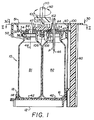
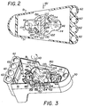
- a holder 10 is generally pie-shaped, Fig. 2, so as to slide in and out of a wet chemistry analyzer, as is conventional (not shown), generally in a circular arrangement of such holders.
- Such a bottle holder 10 comprises, Fig. 1, a base 12, a top member 30, and a sidewall 60 extending between and joined to the base and top member.
- base 12 comprises a platform having at least one recess and preferably recesses 14 and 16, for each of two open mouth bottles B1 and B2 held by holder 10.
- recesses 14 and 16 are disposed along the length of holder 10, which is the dimension that aligns with a radius of the circular arrangement of such holders in the analyzer (not shown).
- Recess 14 is partially defined by an upstanding lug 18.
- Recess 16 is preferably defined by raised sidewalls.
- Base 12 is joined to side wall 60 by any conventional means, for example by welding, by adhesive, by mechanical latches, and so forth.
- Bottles B1 and B2 preferably hold two different reagent solutions.
- the top member 30 comprises a generally flat plate 32 provided with grommets 34, and depending fingers 36 with snap latches 38 for locking under the rim of the mouth 40 of a bottle B1 or B2 with each grommet 34 in contact with a mouth 40.
- grommets 34 are generally aligned with a center axis 46 of each of mouths 40.
- Each grommet has an exposed exterior surface 47.
- a side skirt 50 wraps partially around plate 32 and engages wall 60 using teeth 90.
- Sidewall 60 can have any desired shape and thickness, but preferably it has a plurality of, for example, four cylindrical apertures 62, Fig. 2, extending the full height of the wall.
- a stack of reaction cuvettes, not shown, preferably is mounted within each aperture.
- the cuvettes are preferably shaped as cups or wells. They nest one inside the other, and the uppermost cuvette is preferably topped with a seal cap to seal off the stack from the atmosphere. The bottom of the stack is sealed within the aperture 62 by virtue of a friction fit between a flange of each cuvette, and the sidewall of the aperture 62.
- Means 100 preferably comprises a shutter 102, Fig. 2, having at least one sealing lobe 104 that actively engages one of the grommets 34 (for bottle B1), and cam follower 120 on the lobe, a cam 130 mounted to engage and disengage the cam follower, and means 150, Fig. 1, for activating cam 130.
- the shutter 102 includes a stud that is journalled within an opening of cover 30, so that stud and shutter 102 are preferably positioned, Figs. 2-3, for rotation about an axis 110 which is preferably substantially aligned with, or on, a line 112, extending from the approximate centers of mouths 44 of the grommets as determined by axes 46.
- shutter 102 includes a second lobe 114 as well as first lobe 104.
- lobe 114 is disposed 180° about axis 110, to actively engage the other grommet 34 (for bottle B2), Fig. 2.
- actively engage what is meant herein is preferably a sliding movement of each lobe in frictional contact with the exterior surface 47 of the respective grommet, Fig. 1. In this manner, the shutter via its lobes opens and closes access to the interior of the grommet and therefore its respective bottle.
- Cam followers 120 are provided, one for each lobe. Preferably they have an L-shape with an inner corner 122, and a shorter leg 124, a longer leg 126, extending from the corner. It is these legs 124,126 that are engaged by the cam 130, as shown in phantom, to force shutter 102 to rotate open, arrow 132, or closed, arrows 133, Fig. 3.
- cam followers can have other shapes, for example, that of a 90° arc about an imaginary center 134, Fig. 2.
- Cam 130 is driven by a suitable means 140, such as a drive shaft 142, Fig. 1, operated by a conventional stepper motor (not shown).
- a suitable means 140 such as a drive shaft 142, Fig. 1, operated by a conventional stepper motor (not shown).
- cam 130 can be rotated by a pulley or by a rack and pinion gear (not shown) with the pinion gear being located on the shaft 142.
- a stop pin 150 preferably extends fixedly from the top surface 32 of cover 30, Figs. 3 and 4. This cooperates with a slot or groove 152 formed in shutter 102, the slot 152 having two opposed ends 154, 156 that cooperate with stop pin 150 to prevent over-rotation in either the open position, Fig. 3, or the closed position, Fig. 4
- slot 152 need not be completely enclosed within shutter 102. Instead, portion 158 which completely encloses pin 150 can be removed along the dotted lines Fig. 4.
- skirt 50 is only partially wrapped around to provide upstanding shoulders 51. That is, a cut-out 160 is provided in shoulders to allow access of cam 130 to the cam followers without raising the cam and lowering it - arrow 161, Fig. 2.
- an aspirator probe P can be inserted by the analyzer in which holder 10 is placed, to aspirate out some of the contents of either bottle (shown as B2 in Fig. 1).
- Grommets 34 preferably comprise an elastomer that provides a hardness of at least 45 durometers Shore A, is inert to the contents of bottles B1 and B2, does not outgas, deforms slightly without taking a "set", as is known in the art, and is non-sticky, that is, has a coefficient of friction of no greater than 0.5 when engaged with a polypropylene or polyethylene shutter 102.
- hardnesses of 45, 60 and 75 durometers Shore A are considered useful, with 45 being most preferred. Any elastomer meeting these conditions will suffice.
- the elastomer of choice is a silicone - modified thermoplastic elastomer such as that available under the trade name "C-Flex R70-081" from Concept Polymer Tech.
- Another useful example is a polypropylene EPDM elastomer available under the trade name "Vista-flex” from Advanced Elastomer Systems.
- the material of at least the under-surface 162 of shutter 102, Fig. 1, in contact with grommets 34 is preferably polypropylene or polyethylene.
- other polymeric materials providing a very low moisture-vapor transmissibility (leakage) through the contacting under-surface 162, can be used, provided they also provide the same order of coefficient of frictional engagement with the grommet material as described above.
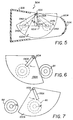
- shutter 102 can be constructed to open one at a time, and close both together, Figs. 5-7. Parts similar to those previously described bear the same reference numerals, to which the distinguishing suffix "A" has been appended.
- cover 30A has a skirt 50A, grommet 34A shown in phantom, and shutter 102A pivoted about an axis 110A by a cam 130A acting on cam followers 120A disposed on respective lobes 104A and 114A of shutter 102A, as before.
- lobes 104A and 114A are disposed rotationally approximately 90° about axis 110A, and said axis is moved substantially away from line 112A connecting the approximate centers of grommets 34A.
- axis 110A is located near one of the shoulders 51A formed by skirt 50A. Cut-outs 160A are then disposed to allow either lobe 104A or lobe 114A to move therethrough (shown in phantom), depending on which side (skirt 51A) axis 110A is located next to.
- this construction allows shutter 102A to either close both grommets (of both bottles), as shown in solid on Fig. 5, to open only the grommet of bottle B1, Fig. 6, or to open only the grommet of bottle B2, Fig. 7, as actuated by cam 130A being rotated about axis 110A.
- cover 30B has mounted therein grommets 34B which slideably and frictionally engage a shutter 102B comprising two lobes 104B, 114B, each with a cam followerg 120B engaged by a cam 130B, shutter 102B being restrained by stop pin 150B, as in the previous embodiments.
- shutter 102B in this case is driven only linearly, arrow 300, in accordance with the linear movement of cam 130 (as driven, for example, by a rack and pinion gear (not shown) the rack gear being affixed to cam 130A).
- An additional stop pin 150A' is added, along with additional slot 152B'. The result is that the grommets are both closed off, as shown in solid, or one or the other is opened, as shown by the 2 phantom positions of the respective lobes.
Abstract
Description
Claims (10)
- A bottle holder (10), for holding a first (B1) and second (B2) bottle of liquid, each bottle (B1,B2) comprising a container with an open mouth (40), the holder (10) comprising: support walls (60) constructed to hold the bottles (B1,B2); the holder characterised in that it also comprises: a grommet (34) having a through-aperture (44) and disposed by the support walls (60) for location adjacent the mouth (40) of each container for closing off the mouth (40) except for the through-aperture (44); and a closure means (100) for opening and closing the grommet apertures (44), and hence the container mouth (40), on demand,
the closure means (100) comprising a shutter (102), means in the bottle holder (10) for mounting the shutter (102) for sliding movement, in contact with and relative to the grommets (34), between a first and a second position, one of the positions being that which closes off at least one of the grommet apertures (44) and the other of the positions that which opens the at least one grommet aperture (44), the shutter (102) further including at least one sealing lobe (104) shaped and sized to close off a grommet aperture (44) when the shutter lobe (104) is in one of the positions, the lobe (104) being operatively disposed so as to move into and out of the positions in response to movement of the shutter (102). - The holder (10) of claim 1, wherein the closure means (100) further comprises a cam follower (120) on the shutter (102), a cam (130) mounted for movement above the shutter (102) into and out of contact with the cam follower (120), and means (150) for moving the cam (130) into and out of the contact.
- The holder (10) of claim 1 or claim 2, wherein the mounting means for the shutter (102) is constructed to mount the shutter (102) for linear translation between the positions.
- The holder (10) of claim 1 or claim 2, wherein the mounting means for the shutter (102) is constructed to mount the shutter (102) for rotation about an axis (110) between the positions.
- The holder (10) of claim 4 when dependent on claim 2, wherein the cam (130) is mounted for rotation about the axis (110).
- The holder (10) of claim 4 or claim 5, wherein the shutter (102) comprises two lobes (104,114) angularly disposed from each other about the rotational axis (110) so that one is 90° from the other, and the axis (110) is located substantially away from a line (112) extending between the approximate centers of the grommet apertures (44), so that when one grommet aperture (44) is closed by one of the lobes, the other (44) can be open.
- The holder (10) of claim 4 or claim 5, wherein the shutter comprises two lobes (104,114) angularly disposed from each other about the rotational axis (110) so that one is 180° from the other, and the axis (110) is located substantially on a line (112) extending between the approximate centers of the grommet apertures (44), so that when one grommet aperture (44) is closed by one of the lobes (104), the other (44) is also closed.
- The holder (10) of any one of claim 4 to 7, wherein the axis (110) is located outside of a line (112) drawn between the approximate centers of the grommet apertures (44).
- The holder (10) of any one of claims 1 to 8, wherein the grommet apertures (44) are preformed so that they do not produce particles that fall into the reagent upon penetration of the an aspirator.
- The holder (10) of any one of claims 1 to 9, wherein each of the grommets (34) comprises an elastomer, such as a silicone-modified thermoplastic elastomer, that provides a hardness of at least 45 durometers Shore A, is inert to the contents of the bottles (B1,B2), does not outgas, deforms slightly without taking a "set", and has a coefficient of friction no greater than 0.5 when engaged by a shutter comprising polypropylene or polyethylene.
Applications Claiming Priority (2)
| Application Number | Priority Date | Filing Date | Title |
|---|---|---|---|
| US08/412,423 US5582222A (en) | 1995-03-29 | 1995-03-29 | Bottle closure mechanism using a sliding shutter |
| US412423 | 1995-03-29 |
Publications (3)
| Publication Number | Publication Date |
|---|---|
| EP0734963A2 EP0734963A2 (en) | 1996-10-02 |
| EP0734963A3 EP0734963A3 (en) | 1997-03-05 |
| EP0734963B1 true EP0734963B1 (en) | 1998-11-25 |
Family
ID=23632909
Family Applications (1)
| Application Number | Title | Priority Date | Filing Date |
|---|---|---|---|
| EP96302195A Expired - Lifetime EP0734963B1 (en) | 1995-03-29 | 1996-03-28 | Bottle closure mechanism using a sliding shutter |
Country Status (7)
| Country | Link |
|---|---|
| US (1) | US5582222A (en) |
| EP (1) | EP0734963B1 (en) |
| JP (1) | JP3029592U (en) |
| AT (1) | ATE173654T1 (en) |
| AU (1) | AU694616B2 (en) |
| CA (1) | CA2172012C (en) |
| DE (1) | DE69601005T2 (en) |
Cited By (6)
| Publication number | Priority date | Publication date | Assignee | Title |
|---|---|---|---|---|
| US9513303B2 (en) | 2013-03-15 | 2016-12-06 | Abbott Laboratories | Light-blocking system for a diagnostic analyzer |
| US9993820B2 (en) | 2013-03-15 | 2018-06-12 | Abbott Laboratories | Automated reagent manager of a diagnostic analyzer system |
| USD890358S1 (en) | 2018-10-03 | 2020-07-14 | Baxalta GmbH | Container unit |
| USD893046S1 (en) | 2018-10-03 | 2020-08-11 | Baxalta GmbH | Container unit |
| US11219578B2 (en) | 2015-06-19 | 2022-01-11 | Takeda Pharmaceutical Company Limited | Pooling device for single or multiple medical containers |
| US11903900B2 (en) | 2018-10-03 | 2024-02-20 | Takeda Pharmaceutical Company Limited | Packaging for multiple containers |
Families Citing this family (16)
| Publication number | Priority date | Publication date | Assignee | Title |
|---|---|---|---|---|
| US5881922A (en) * | 1996-10-15 | 1999-03-16 | The Coca-Cola Company | Coupler switchable among multiple apertures |
| US5945071A (en) * | 1998-04-10 | 1999-08-31 | Abbott Laboratories | Carrier for cuvettes |
| US5948691A (en) * | 1998-04-10 | 1999-09-07 | Abbott Laboratories | Carrier and method of use |
| US7846395B2 (en) | 2003-07-16 | 2010-12-07 | Ortho-Clinical Diagnostics, Inc. | Container closure and device to install and remove closure |
| JP4202891B2 (en) * | 2003-10-31 | 2008-12-24 | 株式会社吉野工業所 | Liquid ejector |
| DE102004043883B4 (en) * | 2004-09-10 | 2007-04-19 | Bartec Gmbh | Sample bottles and methods for sampling |
| US7569189B2 (en) * | 2005-03-30 | 2009-08-04 | Ortho-Clinical Diagnostics, Inc. | Opening and closing a container |
| JP4861787B2 (en) * | 2006-10-10 | 2012-01-25 | シスメックス株式会社 | Reagent container and reagent container holder |
| US8728413B2 (en) * | 2007-02-08 | 2014-05-20 | Biokit, S.A. | Reagent container pack |
| US7793678B2 (en) * | 2007-10-31 | 2010-09-14 | Lancer Partnership, Ltd | Method and apparatus for converter valve |
| EP2760757A2 (en) * | 2011-09-27 | 2014-08-06 | The Board of Regents of The University of Texas System | Robotic infusion mixer and transportable cartridge |
| US8684433B2 (en) | 2012-04-26 | 2014-04-01 | Baxter International Inc. | Packaging for multiple medical containers |
| WO2014002956A1 (en) * | 2012-06-25 | 2014-01-03 | 協和メデックス株式会社 | Container opening/closing device |
| WO2014144759A1 (en) | 2013-03-15 | 2014-09-18 | Abbott Laboratories | Linear track diagnostic analyzer |
| US10252897B2 (en) * | 2017-05-18 | 2019-04-09 | Travis Thompson | Self-sealing bottle holder |
| USD886611S1 (en) | 2018-10-03 | 2020-06-09 | Baxalta GmbH | Container unit |
Family Cites Families (11)
| Publication number | Priority date | Publication date | Assignee | Title |
|---|---|---|---|---|
| US2159978A (en) * | 1938-07-30 | 1939-05-30 | Winfred T Parkin | Container closure |
| US2554444A (en) * | 1947-03-06 | 1951-05-22 | Scovill Manufacturing Co | Two-walled cap for container of granular material with sifter closure mounted between said two walls for rotation about longitudinal container axis |
| US2878829A (en) * | 1956-03-16 | 1959-03-24 | Union Tank Car Co | Valve mechanism |
| US3337082A (en) * | 1965-01-13 | 1967-08-22 | Henri J Dorgelys | Containers and storage facilities therefor |
| US4224958A (en) * | 1977-12-19 | 1980-09-30 | Kaplan Stephen J | Valve device for diverting and combining fluid flows |
| US5039615A (en) * | 1987-04-11 | 1991-08-13 | Kabushiki Kaisha Kyoto Daiichi Kagaku | Method for chemically analyzing a test piece |
| US4844872A (en) * | 1987-07-17 | 1989-07-04 | Fisher Scientific Company | Fluid handling |
| US5064086A (en) * | 1991-01-31 | 1991-11-12 | Mcentee James E | Container lid |
| US5322668A (en) * | 1993-07-01 | 1994-06-21 | Eastman Kodak Company | Locked bottle holder |
| US5542575A (en) * | 1993-07-09 | 1996-08-06 | Dade Interantional Inc. | Liquid reagent container having a primary and secondary closure mechanism |
| US5398846A (en) * | 1993-08-20 | 1995-03-21 | S. C. Johnson & Son, Inc. | Assembly for simultaneous dispensing of multiple fluids |
-
1995
- 1995-03-29 US US08/412,423 patent/US5582222A/en not_active Expired - Lifetime
-
1996
- 1996-03-18 CA CA002172012A patent/CA2172012C/en not_active Expired - Fee Related
- 1996-03-21 AU AU48249/96A patent/AU694616B2/en not_active Ceased
- 1996-03-28 AT AT96302195T patent/ATE173654T1/en not_active IP Right Cessation
- 1996-03-28 DE DE69601005T patent/DE69601005T2/en not_active Expired - Fee Related
- 1996-03-28 EP EP96302195A patent/EP0734963B1/en not_active Expired - Lifetime
- 1996-03-29 JP JP1996002345U patent/JP3029592U/en not_active Expired - Lifetime
Cited By (9)
| Publication number | Priority date | Publication date | Assignee | Title |
|---|---|---|---|---|
| US9513303B2 (en) | 2013-03-15 | 2016-12-06 | Abbott Laboratories | Light-blocking system for a diagnostic analyzer |
| US9993820B2 (en) | 2013-03-15 | 2018-06-12 | Abbott Laboratories | Automated reagent manager of a diagnostic analyzer system |
| US10330691B2 (en) | 2013-03-15 | 2019-06-25 | Abbott Laboratories | Light-blocking system for a diagnostic analyzer |
| US11219578B2 (en) | 2015-06-19 | 2022-01-11 | Takeda Pharmaceutical Company Limited | Pooling device for single or multiple medical containers |
| US11684548B2 (en) | 2015-06-19 | 2023-06-27 | Takeda Pharmaceutical Company Limited | Pooling device for single or multiple medical containers |
| USD890358S1 (en) | 2018-10-03 | 2020-07-14 | Baxalta GmbH | Container unit |
| USD893046S1 (en) | 2018-10-03 | 2020-08-11 | Baxalta GmbH | Container unit |
| USD935638S1 (en) | 2018-10-03 | 2021-11-09 | Takeda Pharmaceutical Company Limited | Container unit |
| US11903900B2 (en) | 2018-10-03 | 2024-02-20 | Takeda Pharmaceutical Company Limited | Packaging for multiple containers |
Also Published As
| Publication number | Publication date |
|---|---|
| JP3029592U (en) | 1996-10-01 |
| AU694616B2 (en) | 1998-07-23 |
| CA2172012A1 (en) | 1996-09-30 |
| EP0734963A3 (en) | 1997-03-05 |
| EP0734963A2 (en) | 1996-10-02 |
| CA2172012C (en) | 2006-12-12 |
| DE69601005D1 (en) | 1999-01-07 |
| ATE173654T1 (en) | 1998-12-15 |
| DE69601005T2 (en) | 1999-04-29 |
| AU4824996A (en) | 1996-10-10 |
| US5582222A (en) | 1996-12-10 |
Similar Documents
| Publication | Publication Date | Title |
|---|---|---|
| EP0734963B1 (en) | Bottle closure mechanism using a sliding shutter | |
| US8529847B2 (en) | Reagent kit for analyzing apparatus | |
| CA2305990C (en) | Closure appliance for reagent containers | |
| CA2512707A1 (en) | Automatic closure of containers | |
| EP0820813A2 (en) | A closure | |
| US7897123B2 (en) | Reagent vessel cap and method for collecting reagent | |
| CA2633566C (en) | Packaging cassette for reagent carriers | |
| EP0356883B1 (en) | Vortex mixer drive | |
| EP0764119B1 (en) | Container with screw cap | |
| US7648037B2 (en) | Lid structure of reagent container | |
| US20180036734A1 (en) | Reaction vessel and apparatus and method for opening and closing a reaction vessel | |
| JP3019213B2 (en) | Ball and socket lid for sample collection container | |
| JPH11171218A (en) | Ball and socket lid for sample collection container incorporating dimple lock mechanism | |
| EP0754496A1 (en) | Plate assembly useful for microbiological laboratory procedures | |
| JP3956294B2 (en) | Prevention method for reagent container cap and reagent evaporation | |
| US8613893B2 (en) | Sealing member, cap for reagent container, and reagent container | |
| US20020170930A1 (en) | Fluid dispensing closure and method of manufacturing same | |
| JPH10311835A (en) | Reagent stocker of automatic analyzer | |
| WO2020059231A1 (en) | Automatic analysis device | |
| JPWO2021171722A5 (en) | ||
| TW202402632A (en) | Reticle container having rotating connector with spring force latching | |
| JPH04161855A (en) | Evaporatio preventing method for reagent | |
| JPH11148938A (en) | Ball and socket lid for sample collection container having integrated pour mouth |
Legal Events
| Date | Code | Title | Description |
|---|---|---|---|
| PUAI | Public reference made under article 153(3) epc to a published international application that has entered the european phase |
Free format text: ORIGINAL CODE: 0009012 |
|
| AK | Designated contracting states |
Kind code of ref document: A2 Designated state(s): AT BE CH DE DK FR GB GR IT LI MC NL SE |
|
| AX | Request for extension of the european patent |
Free format text: SI PAYMENT 960415 |
|
| RAX | Requested extension states of the european patent have changed |
Free format text: SI PAYMENT 960415 |
|
| PUAL | Search report despatched |
Free format text: ORIGINAL CODE: 0009013 |
|
| RHK1 | Main classification (correction) |
Ipc: B01L 9/00 |
|
| AK | Designated contracting states |
Kind code of ref document: A3 Designated state(s): AT BE CH DE DK FR GB GR IT LI MC NL SE |
|
| AX | Request for extension of the european patent |
Free format text: SI PAYMENT 960415 |
|
| 17P | Request for examination filed |
Effective date: 19970811 |
|
| 17Q | First examination report despatched |
Effective date: 19971007 |
|
| GRAG | Despatch of communication of intention to grant |
Free format text: ORIGINAL CODE: EPIDOS AGRA |
|
| GRAG | Despatch of communication of intention to grant |
Free format text: ORIGINAL CODE: EPIDOS AGRA |
|
| GRAH | Despatch of communication of intention to grant a patent |
Free format text: ORIGINAL CODE: EPIDOS IGRA |
|
| GRAH | Despatch of communication of intention to grant a patent |
Free format text: ORIGINAL CODE: EPIDOS IGRA |
|
| GRAA | (expected) grant |
Free format text: ORIGINAL CODE: 0009210 |
|
| AK | Designated contracting states |
Kind code of ref document: B1 Designated state(s): AT BE CH DE DK FR GB GR IT LI MC NL SE |
|
| AX | Request for extension of the european patent |
Free format text: SI PAYMENT 960415 |
|
| PG25 | Lapsed in a contracting state [announced via postgrant information from national office to epo] |
Ref country code: SE Free format text: THE PATENT HAS BEEN ANNULLED BY A DECISION OF A NATIONAL AUTHORITY Effective date: 19981125 Ref country code: NL Free format text: LAPSE BECAUSE OF FAILURE TO SUBMIT A TRANSLATION OF THE DESCRIPTION OR TO PAY THE FEE WITHIN THE PRESCRIBED TIME-LIMIT Effective date: 19981125 Ref country code: GR Free format text: LAPSE BECAUSE OF NON-PAYMENT OF DUE FEES Effective date: 19981125 Ref country code: BE Free format text: LAPSE BECAUSE OF FAILURE TO SUBMIT A TRANSLATION OF THE DESCRIPTION OR TO PAY THE FEE WITHIN THE PRESCRIBED TIME-LIMIT Effective date: 19981125 Ref country code: AT Free format text: LAPSE BECAUSE OF FAILURE TO SUBMIT A TRANSLATION OF THE DESCRIPTION OR TO PAY THE FEE WITHIN THE PRESCRIBED TIME-LIMIT Effective date: 19981125 |
|
| REF | Corresponds to: |
Ref document number: 173654 Country of ref document: AT Date of ref document: 19981215 Kind code of ref document: T |
|
| REG | Reference to a national code |
Ref country code: CH Ref legal event code: NV Representative=s name: E. BLUM & CO. PATENTANWAELTE Ref country code: CH Ref legal event code: EP |
|
| REF | Corresponds to: |
Ref document number: 69601005 Country of ref document: DE Date of ref document: 19990107 |
|
| ET | Fr: translation filed | ||
| ITF | It: translation for a ep patent filed |
Owner name: SOCIETA' ITALIANA BREVETTI S.P.A. |
|
| PG25 | Lapsed in a contracting state [announced via postgrant information from national office to epo] |
Ref country code: DK Free format text: LAPSE BECAUSE OF FAILURE TO SUBMIT A TRANSLATION OF THE DESCRIPTION OR TO PAY THE FEE WITHIN THE PRESCRIBED TIME-LIMIT Effective date: 19990225 |
|
| NLV1 | Nl: lapsed or annulled due to failure to fulfill the requirements of art. 29p and 29m of the patents act | ||
| PG25 | Lapsed in a contracting state [announced via postgrant information from national office to epo] |
Ref country code: MC Free format text: LAPSE BECAUSE OF NON-PAYMENT OF DUE FEES Effective date: 19990930 |
|
| PLBE | No opposition filed within time limit |
Free format text: ORIGINAL CODE: 0009261 |
|
| STAA | Information on the status of an ep patent application or granted ep patent |
Free format text: STATUS: NO OPPOSITION FILED WITHIN TIME LIMIT |
|
| 26N | No opposition filed | ||
| REG | Reference to a national code |
Ref country code: GB Ref legal event code: IF02 |
|
| REG | Reference to a national code |
Ref country code: CH Ref legal event code: PFA Owner name: JOHNSON & JOHNSON CLINICAL DIAGNOSTICS, INC. Free format text: JOHNSON & JOHNSON CLINICAL DIAGNOSTICS, INC.#100 INDIGO CREEK DRIVE#ROCHESTER, NEW YORK 14650-0880 (US) -TRANSFER TO- JOHNSON & JOHNSON CLINICAL DIAGNOSTICS, INC.#100 INDIGO CREEK DRIVE#ROCHESTER, NEW YORK 14650-0880 (US) |
|
| PGFP | Annual fee paid to national office [announced via postgrant information from national office to epo] |
Ref country code: CH Payment date: 20080313 Year of fee payment: 13 |
|
| PGFP | Annual fee paid to national office [announced via postgrant information from national office to epo] |
Ref country code: FR Payment date: 20080311 Year of fee payment: 13 Ref country code: DE Payment date: 20080407 Year of fee payment: 13 |
|
| PGFP | Annual fee paid to national office [announced via postgrant information from national office to epo] |
Ref country code: GB Payment date: 20080402 Year of fee payment: 13 |
|
| REG | Reference to a national code |
Ref country code: CH Ref legal event code: PL |
|
| GBPC | Gb: european patent ceased through non-payment of renewal fee |
Effective date: 20090328 |
|
| REG | Reference to a national code |
Ref country code: FR Ref legal event code: ST Effective date: 20091130 |
|
| PG25 | Lapsed in a contracting state [announced via postgrant information from national office to epo] |
Ref country code: LI Free format text: LAPSE BECAUSE OF NON-PAYMENT OF DUE FEES Effective date: 20090331 Ref country code: DE Free format text: LAPSE BECAUSE OF NON-PAYMENT OF DUE FEES Effective date: 20091001 Ref country code: CH Free format text: LAPSE BECAUSE OF NON-PAYMENT OF DUE FEES Effective date: 20090331 |
|
| PG25 | Lapsed in a contracting state [announced via postgrant information from national office to epo] |
Ref country code: GB Free format text: LAPSE BECAUSE OF NON-PAYMENT OF DUE FEES Effective date: 20090328 Ref country code: FR Free format text: LAPSE BECAUSE OF NON-PAYMENT OF DUE FEES Effective date: 20091123 |
|
| PGFP | Annual fee paid to national office [announced via postgrant information from national office to epo] |
Ref country code: IT Payment date: 20140310 Year of fee payment: 19 |
|
| PG25 | Lapsed in a contracting state [announced via postgrant information from national office to epo] |
Ref country code: IT Free format text: LAPSE BECAUSE OF NON-PAYMENT OF DUE FEES Effective date: 20150328 |