EP0734951A2 - Apparatus and method for vacuum sealing pouches - Google Patents
Apparatus and method for vacuum sealing pouches Download PDFInfo
- Publication number
- EP0734951A2 EP0734951A2 EP96103240A EP96103240A EP0734951A2 EP 0734951 A2 EP0734951 A2 EP 0734951A2 EP 96103240 A EP96103240 A EP 96103240A EP 96103240 A EP96103240 A EP 96103240A EP 0734951 A2 EP0734951 A2 EP 0734951A2
- Authority
- EP
- European Patent Office
- Prior art keywords
- pouch
- snorkel
- guide member
- heat
- sealing
- Prior art date
- Legal status (The legal status is an assumption and is not a legal conclusion. Google has not performed a legal analysis and makes no representation as to the accuracy of the status listed.)
- Granted
Links
Images


Classifications
-
- B—PERFORMING OPERATIONS; TRANSPORTING
- B65—CONVEYING; PACKING; STORING; HANDLING THIN OR FILAMENTARY MATERIAL
- B65B—MACHINES, APPARATUS OR DEVICES FOR, OR METHODS OF, PACKAGING ARTICLES OR MATERIALS; UNPACKING
- B65B31/00—Packaging articles or materials under special atmospheric or gaseous conditions; Adding propellants to aerosol containers
- B65B31/04—Evacuating, pressurising or gasifying filled containers or wrappers by means of nozzles through which air or other gas, e.g. an inert gas, is withdrawn or supplied
- B65B31/06—Evacuating, pressurising or gasifying filled containers or wrappers by means of nozzles through which air or other gas, e.g. an inert gas, is withdrawn or supplied the nozzle being arranged for insertion into, and withdrawal from, the mouth of a filled container and operating in conjunction with means for sealing the container mouth
Abstract
Description
- The invention relates to an apparatus for packaging objects. More particularly, the invention relates to an apparatus and method for vacuum sealing objects in various size pouches.
- A variety of apparatus and methods are known for wrapping or pouching objects in containers, particularly objects made from flexible materials. Such known apparatus and methods are limited in their abilities to adjust readily for changes in the size of the objects, the size or format of the container, or both. Many such known apparatus and methods are also limited in their abilities to wrap or pouch objects which require more gentle handling due to their ease of damage or their unstable structure. For example, stacks of slippery sheets of x-ray film or photographic paper must be handled carefully due to the sensitivity of the film to scratches, pressure marks, and the like. In addition, stacks of sheets of such objects having slippery surface properties are easily shifted out of their desired right-rectangular stack configuration, thereby producing an irregularly shaped, skewed stack which is difficult to handle and package. Often, the objects are vacuum sealed in the pouch so that the objects will not slide from their stack configuration. The amount of vacuum affects the packaging quality, as does the heat seal required to maintain the vacuum within the sealed pouch. The vacuum and seal must be sufficient to secure the objects within the pouch, yet allow a user to tear the pouch open to access the objects.
- FIG 1 shows a pouch and an object of some typical types.
Pouch 10 can be formed from a pair of preferably congruent opposedside walls peripheral seal 16, such as a continuous heat seal, but unjoined on one side, thereby forming an opening ormouth 18. The joined sides may include flaps, rip strips, or other features desired for a particular application. A typical object to be packaged would be a single object or an essentially rightrectangular stack 20 of sheet material. The top and bottom sheet ofstack 20 may be covered bydunnage cards pouch 10,pouch 10 can be evacuated of air which causesside walls Mouth 18 can be closed by aseal 26, to produce a packaged object of the general configuration shown in FIG 2. - US-A-5,265,397, commonly assigned, herein incorporated by reference, relates to a flexible apparatus and process for loading and sealing pouches. FIG 3 discloses
pouch 10 positioned for evacuating and sealing. Apouch evacuation apparatus 28 is provided which comprises apneumatic actuator 30. The actuator rod ofactuator 30 extends toward the rear of the apparatus and fixedly supports atransverse support block 32 for a pair of evacuator probes ortubes 34, only one of which appears in FIG 3.Probes 34 are positioned essentially on the centerline of the open mouth ofpouch 10, and are connected to a suitable vacuum source. Above and belowprobes 34 are mounted upper and lower pouch closing and sealingjaws 36 which comprise upper and lower pairs ofpneumatic actuators 38 havingactuator rods 40 which support transversely extendingmounting bars 42. Attached tobars 42 are pairs of aligned, oppositely facing and transversely extending heat sealing bars orjaws 44.Actuator rods 46 of upper and lower pairs ofpneumatic actuators 48 support aligned, oppositely facing and transversely extending pouch closing bars or clampingjaws 50, each having alayer 52 of foam rubber or similar resilient material on its surface facingprobes 34.Actuator 30 extendsprobes 34 through the mouth ofpouch 10 into fairly close proximity to the enclosed object.Actuators 48 are then actuated to extend clampingjaws 50 into contact with the side walls ofpouch 10, thus compressinglayers 52 to provide a mechanical seal between the side walls and around theextended probes 34. Vacuum is then applied toprobes 34 for a time sufficient to evacuate the pouch, after whichprobes 34 are withdrawn behindsealing edges 44, but with the vacuum still being drawn.Actuators 38 are then actuated to presssealing jaws 44 into contact withpouch 10 to formseal 26 and complete the package. Vacuum is then stopped andactuators - While the apparatus disclosed in US-A-5,265,397 has achieved a level of success, the vacuum levels in the completed pouches may vary. Accordingly, there continues to be a need for an apparatus which provides precise control of the vacuum during the vacuum sealing process, provides consistent vacuum levels in the completed pouches, achieves high levels of vacuum during the vacuum sealing process. There also continues to be a need for such an apparatus which does not clog during the vacuum sealing process. Further, a need continues for a method for selectively heat sealing the pouches to provide a heat seal.
- An object of the invention is to provide a packaging apparatus whose vacuum levels can be precisely controlled, provides consistent vacuum levels in the packaged object, and achieves high levels of vacuum during the vacuum sealing process.
- A further object of the invention is to provide a apparatus which forms a mechanical seal during the evacuation process.
- Another object of the invention is to provide an apparatus which does not clog during the vacuum sealing process.
- Yet another object of the invention is to provide a method for selectively controlling the heat sealing process.
- These objects are given only by way of illustrative examples; thus, other desirable objectives and advantages inherently achieved by the disclosed invention may occur or become apparent to those skilled in the art. The invention is defined by the appended claims.
- According to one aspect of the invention, an apparatus is provided for packaging an object in a pouch, the pouch having an opposed pair of side walls joined to form an open mouth. A frame with a support surface supports the pouch and a snorkel assembly. The snorkel assembly includes a snorkel guide member telescopically surrounding a probe. The probe moves axially relative to the snorkel guide member and has an end adapted to be inserted into the pouch through the open mouth. Means are provided to move probe between an extended within the pouch and a withdrawn position. The probe includes an axial channel through which air can flow. When vacuum is applied to the axial channel, air can be removed from the pouch. A clamp assembly is transversely mounted relative to the snorkel assembly, and includes a pair of clamping jaws which move relative to each other between an open and closed position. The clamping jaws engage and clamp the pouch around the snorkel guide member when the clamping jaws close. A seal assembly is transversely mounted relative to the snorkel assembly and is positioned between the object in the pouch and the clamp assembly. The seal assembly has a pair of sealing jaws which move between an open and closed position. In the closed position, the sealing jaws engage the pouch therebetween to form a seal in the open mouth.
- According to another aspect of the invention, the apparatus comprises a frame with a support surface supporting the pouch and a snorkel assembly. The snorkel assembly includes a snorkel guide member telescopically surrounding a probe. The probe moves axially relative to the snorkel guide member and has an end adapted to be inserted into the pouch through the open mouth. Means are provided to move probe between an extended within the pouch and a withdrawn position. The probe includes an axial channel through which air can flow. When vacuum is applied to the axial channel, air can be removed from the pouch. A clamp assembly is transversely mounted relative to the snorkel assembly, and includes a pair of clamping jaws which move relative to each other between an open and closed position. The clamping jaws each include a clamping notch, where the clamping notches define an aperture geometrically similar to an external configuration of the snorkel guide member. The clamping notches engage and clamp the pouch around the snorkel guide member when the clamping jaws are in their closed position. A seal assembly is transversely mounted relative to the snorkel assembly and is positioned between the object in the pouch and the clamp assembly. The seal assembly has a pair of sealing jaws which move between an open and closed position. In the closed position, the sealing jaws engage the pouch therebetween to form a seal in the open mouth.
- According to yet a further aspect of the invention, a method is provided for packaging an object in a pouch. The method comprising the steps of: providing a snorkel assembly having a snorkel guide member telescopically surrounding a probe, the probe including an end and an axial channel through which air can flow, the probe being axially movable relative to the snorkel guide member; extending the end of the probe from the snorkel guide member; inserting the end of the probe into the pouch through the open mouth; clamping the pouch around the snorkel guide member; applying a vacuum to the axial channel to remove air from the pouch; withdrawing the end of the probe into the snorkel guide member; engaging the open mouth of the pouch between a first and second sealing jaw; disengaging the vacuum to the axial channel; applying heat to the first and second sealing jaws to heat seal the open mouth of the pouch; disengaging the first and second sealing jaws; and unclamping the pouch from around the snorkel guide member.
- According to yet a further aspect of the invention, there is provided a method for selectively applying heat to a sealing jaw to heat seal an open mouth of a pouch. The method includes the steps of:
selecting a total heat cycle time during which heat can be applied by the sealing jaw to the pouch; selecting a cycle time increment which is less than the total heat cycle time; selecting a minimum time increment during which heat can be applied to the sealing jaw, the minimum time increment being less than the cycle time increment; selecting a maximum time increment during which heat can be applied to the sealing jaw, the maximum time increment being greater than or equal to the minimum time increment, and being less than the cycle time increment; selecting a desired temperature at which to heat the sealing jaw to form the heat seal; and selecting a baseline temperature by which to regulate the application of heat to the sealing jaw, the baseline temperature being less than the desired temperature. A heating-on time is calculated by
sensing an actual temperature of the sealing jaw, determining a difference between the desired temperature and the actual temperature, setting the heating-on time to the maximum time increment if the difference is greater than or equal to the baseline temperature, setting the heating-on time to a value less than the maximum time increment and greater than zero if the difference is less than the baseline temperature, and greater than zero, and setting the heating-on time to zero if the difference is less than or equal to zero. The sealing jaw is heated for the heating-on time, and then the sealing jaw is cooled by turned off the heat for the remainder of the cycle time increment. The steps of calculating, heating, and cooling are repeated for each cycle time increment until the total heat cycle time is reached. - According to still another aspect of the invention, there is provided an apparatus for selectively applying heat to a sealing jaw to heat seal an open mouth of a pouch. The apparatus includes means for selecting a cycle time increment during which heat can be applied to the sealing jaw; means for selecting a minimum time increment during which heat can be applied to the sealing jaw, the minimum time increment being less than the cycle time increment; means for selecting a maximum time increment during which heat can be applied to the sealing jaw, the maximum time increment being greater than or equal to the minimum time increment, and being less than the cycle time increment; means for selecting a desired temperature at which to heat the sealing jaw to form the heat seal; and means for selecting a baseline temperature by which to regulate the application of heat to the sealing jaw, the baseline temperature being less than the desired temperature. The apparatus further includes means for sensing an actual temperature of the sealing jaw; means for calculating a heating-on time for each cycle time increment based on a difference between the desired temperature and the actual temperature; means for applying heat to the sealing jaw for the heating-on time; and means for turning off heat to the sealing jaw for the remainder of the cycle time increment.
- An advantage of the apparatus of the invention is that it is flexible enough to handle changes in object size, the size or format of the container, or both; allows control of the vacuum during the sealing process; provides consistent vacuum levels in the packaged objects; provides a mechanical seal during evacuation of the pouch; generates a heat seal; achieves a high level of vacuum; provides a non-clogging evacuation system; allows for system set-up by product; and allows for benchmarking (for example, quality checks) of the system.
- The foregoing and other objects, features, and advantages of the invention will be apparent from the following more particular description of the preferred embodiments of the invention, as illustrated in the accompanying drawings.
- FIG. 1 shows a perspective view of an object and pouch of a type known in the art, but useful in the apparatus of the invention.
- FIG. 2 shows a perspective view of a completed package of a type closed and sealed by the apparatus of the invention.
- FIG. 3 shows a section view of a prior art apparatus for closing and sealing a pouch of the type illustrated in FIG. 1 and FIG. 2.
- FIG. 4 shows a top view of the apparatus of the invention.
- FIG. 5 shows a side view of the snorkel assembly of the invention.
- FIG. 6 shows an enlarged end view of the snorkel assembly, as seen from the right in FIG. 5.
- FIG. 7(a) shows a first embodiment of a section view through the apparatus of the invention, taken along line 7-7 of FIG. 4.
- FIG. 7(b) shows a second embodiment of a section view through the apparatus of the invention, taken along line 7-7 of FIG. 4.
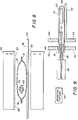
- FIG. 8 shows a section view through the apparatus of the invention, taken along line 8-8 of FIG. 4.
- FIG. 9 shows a section view through the apparatus of the invention, taken along line 9-9 of FIG. 4.
- FIG. 10 shows the embodiment of the clamping jaws of FIG 7(b) in their closed position.
- FIG. 11 shows a side elevation of the snorkel assembly, and the mounting fixture.
- FIG. 12 shows a flowchart of steps of a method of the invention.
- FIG. 13 shows a flowchart of the steps of heating and cooling the sealing jaws identified in FIG. 12.
- FIG. 14 shows a continuation of the flowchart of FIG. 13.
- FIG. 15 shows a plot of time versus temperature profile for heating the sealing jaws of the invention.
- FIG. 16 shows a plot of time versus heating profile for heating the sealing jaws of the invention, corresponding with FIG. 15.
- The following is a detailed description of the preferred embodiments of the invention, reference being made to the drawings in which the same reference numerals identify the same elements of structure in each of the several figures.
- Referring again to FIG 1, pouches for use in the invention may be made from any suitable material but preferably the material is gas impervious and can be heat sealed. Such pouches can be stacked flat and are readily picked up and moved by conventional means such as suction cup arrays.
Stack 20 may be, for example, x-ray film sheets or photographic paper.Mouth 18 may be held open by conventional means, such as a suction cup array, and the object can be positioned insidepouch 10 throughmouth 18. - FIG 4 shows the apparatus of the invention which comprises a
frame 54 having asupport surface 56, aseal assembly 58 including upper and lower sealingjaws 44, aclamp assembly 60 including upper andlower clamping jaws 50,pouch evacuation assembly 28 including asnorkel assembly 62,.a mountingfixture 64 for mountingsnorkel assembly 62 to frame 54, a snorkel extension means 65, and a vacuum source in association withsnorkel assembly 62. As will be discussed in detail below, whileclamp assembly 60 securespouch 10,snorkel assembly 62 evacuates the air frompouch 10. Once the air is evacuated,seal assembly 58seals pouch 10, and clampassembly 60 then releasespouch 10. -
Support surface 56 supportspouch 10. A source or hopper (not shown) of pouches may be attached or associated withsupport surface 56.Pouches 10 can be removed from the source and oriented onsupport surface 56 by any suitable means, such as manually or with a programmable robot.Support surface 56 may include a guide fixture (not shown) to orientpouch 10 for sealing.Support surface 56 may further include removal means (not shown) for removing filled, evacuated, and sealed packages. - As illustrated in FIG 5 and FIG 6,
snorkel assembly 62 includes asnorkel support member 66, an elongatedsnorkel guide member 68 having anend 69, and an elongated, generallytubular probe 70 having anend 72.Snorkel guide member 68 telescopically surroundsprobe 70. That is, afirst channel 74 extends axially throughsnorkel guide member 68 andsnorkel support member 66.Probe 70 is configured to be closely fit (that is, minimal clearance) withinfirst channel 74, thereby minimizing leakage betweenprobe 70 andfirst channel 74.Probe 70 is movable axially withinchannel 74 so thatprobe end 72 can be extended outward of snorkel guide member end 69 by snorkel extension means 65, for example,pneumatic actuator 30. In such a configuration,probe 70 is a telescoping inner-snorkel which can be extended or retracted (that is, withdrawn) fromsnorkel guide member 68. Asecond channel 76 extends axially throughprobe 70 through which air can flow, allowing for the evacuation ofpouch 10. In an alternate embodiment,snorkel support member 66 telescopically surroundssnorkel guide member 68. That is, snorkel guide member would be movable axially withinsnorkel support member 66, for example, bypneumatic actuator 30, and probe 70 would be movable axially withinsnorkel guide member 68. - Referring now to FIGS 7-10,
seal assembly 58 is positioned transversely to supportsurface 56, so as to be positioned betweenstack 20 and clampingassembly 60. Sealingjaws 44, each having a sealingedge 82, move relative to each other between an open position and a closed position. In the open position, sealingedges 82 are spaced apart from each other to allowpouch 10 andprobe 70 to be positioned therebetween. In the closed position, sealingedges 82 are pressed into contact withpouch 10 to provide a mechanical seal between sealingedges 82 andpouch 10, such that heat can be applied to heat seal the unjoined end ofpouch 10. Conventional actuation means, such aspneumatic actuators 38, can be used to move sealingjaws 44 between their open and closed positions. Those skilled in the art will recognize that the closed position can be accomplished by moving one sealing jaw while holding the other sealing jaw stationary or by moving both sealingjaws 44. Sealingjaws 44 can be of any size, however, the length of sealingedges 82 must be at least the length of the unjoined side ofpouch 10 in order to seal the length. - Various configurations of sealing jaws are known to those skilled in the art. For example, sealing
jaws 44 can comprise a heat conducting element (for example, NICHROME, trademark of the Driver-Harris Company, including nickel and chromium), an insulating material, a support material (for example, aluminum), a heat sensor (for example, thermocouple(s) 86), and a compliant member (for example, rubber) providing compliance to form a seal. A sealing pressure in the range of 50-100 psi (pounds per square inch), preferably 80 psi, is suitable to form a mechanical seal between sealingjaws 44 andpouch 10. -
Clamp assembly 60 is positioned transversely to supportsurface 56 such thatseal assembly 58 is positioned betweenstack 20 and clampassembly 60. As shown in FIGS 7(a) and 7(b),clamp assembly 60 comprises two clampingjaws 50, each with a clampingedge 90. Clampingjaws 50 move relative to each other between an open position and a closed position. In the open position, clampingedges 90 are spaced apart from each other such thatsnorkel guide member 68 andpouch 10 can be positioned therebetween. In the closed position, clampingedges 90 are pressed together to engage and clamppouch 10 aroundsnorkel guide member 68, to provide a mechanical seal between clamping edges 90,snorkel guide member 68, andpouch 10. Conventional actuation means, such aspneumatic actuators 38, can be used to move clampingjaws 50 between their open and closed positions. Those skilled in the art will recognize that the closed position can be accomplished by moving one clamping jaw while holding the other clamping jaw stationary or by moving both clampingjaws 50. Clampingjaws 50 can be of any size, however, the length of clampingedges 90 must be at least the length of the unjoined side ofpouch 10 in order to clamp its length. - Clamping
jaws 50 engage and clampsnorkel guide member 68 aroundpouch 10 to form a mechanical seal between clamping edges 50, clampingedges 90 andpouch 10, betweenpouch 10 andsnorkel guide member 68, and betweensides pouch 10. Clampingjaws 50 can have various configurations to form such a mechanical seal, thereby promoting precision evacuation. In a first embodiment illustrated in FIG 7(a), clamping edges 90 each include a linear edge. In a second embodiment, illustrated in FIG 7(b), clamping edges 90 each include a clampingnotch 94 defining an aperture 98 which can, for example, be configured geometrically similar to the external configuration ofsnorkel guide member 68.Snorkel guide member 68 would then be positioned within aperture 98 (and accordingly, clamping notches 94) when clampingjaws 50 are in their closed position. FIG 10 illustrates clampingjaws 50 in their closed position, so that clampingnotches 94 engagesnorkel guide member 68 andpouch 10. A high clamping force ensures a mechanical hermetic seal, thereby promoting precise control during the vacuum process. - Snorkel guide member 68 (and accordingly, aperture 98 and clamping notches 94), can be of various external configurations (that is, shapes), for example, semi-circular, oval, oblong, or diamond-shaped. FIG 6 illustrates one embodiment of the diamond-shaped configuration of
snorkel guide member 68 wherein the diamond-shaped cross-section is defined by internal angles of 60 degrees and 120 degrees. Likewise,probe 70, andchannels Snorkel guide member 68 and probe 70 can be made of conventional materials, such as DELRIN, aluminum, or stainless steel. - Clamping
jaws 50 can be made of any conventional material, such as aluminum or steel. Clamping edges 90 can likewise be made of the same material as clampingjaws 50, or each clamping edge can havelayer 52 of foam rubber or similar resilient material. Alternatively, only one edge of clampingedges 90 can includelayer 52, for example, of 30-70 durometer polyurethane (preferably 40 durometer), as illustrated in FIG 7(b), while the other edge is of a harder material. A suitable clamping force is in the range of 100-200 psi. - Referring now to FIGS 4-11,-
snorkel assembly 62 is attached to mountingfixture 64. Mountingfixture 64 comprises aflexible coupling 100, such as a rubber coupling, mountingbracket 102 for attachment to frame 54, and aprobe holder 104. While mountingfixture 64 need not includeflexible coupling 100, some flexibility in the mounting is preferable to provide compliance in the system, for example, when engaging and clampingpouch 10 aroundsnorkel guide member 68 between clampingnotches 94;flexible coupling 100 provides such flexibility. Other mounting means for mountingsnorkel assembly 62 will be known to those skilled in the art. - Attached to snorkel
assembly 62 is a tube 106, or other means though which air may flow. A vacuum source or generator 108 in association with tube 106 provides vacuum to evacuate air frompouch 10. Avacuum sensor 110 senses the level of vacuum in tube 106, and accordingly,pouch 10. A Programmable Logic Controller (PLC) 112 directs the level of vacuum sensed byvacuum sensor 110 to vacuum generator 108 by means of a transducer orconverter 113, which converts the voltage signal to a vacuum level. - A method by which the apparatus operates is indicated by the flowchart shown in FIG 12. To perform a packaging operation, clamping
jaws 50 and sealingjaws 44 are oriented to their open position (114).Snorkel assembly 62 is preferably positioned parallel to supportsurface 56 and essentially on the centerline of the open mouth ofpouch 10.Probe 70 can be either extended or retracted fromsnorkel guide member 68. Likewise, ifsnorkel guide member 68 is movable relative to snorkelsupport member 66,snorkel guide member 68 can be extended or retracted fromsnorkel support member 66. For this discussion,snorkel guide member 68 does not move relative to snorkelsupport member 66, and probe 70 is in its extended position (114).Pouch 10 is positioned onsupport surface 56 withmouth 18 facingsnorkel assembly 62, and overhanging frame 54(116).Snorkel guide member 68 andprobe 70 are inserted intomouth 18 ofpouch 10. While the placement ofpouch 10 is dependent on the application,pouch 10 is placed such that it will be engaged by bothseal assembly 58 and clampassembly 60. The placement ofsnorkel assembly 62 relative topouch 10 is dependent on the application. That is, the placement ofsnorkel assembly 62 depends on the size ofpouch 10 and the placement ofstack 20 withinpouch 10. For example, as shown in FIG 4, stack 20 is positioned on the right side ofpouch 10. Accordingly,snorkel assembly 62 is positioned to the left side ofpouch 10. However, snorkel assembly could have been positioned abovestack 20.Snorkel assembly 62 is inserted insidepouch 10 such that clampingnotches 94 will close oversnorkel guide member 68 andpouch 10, and not close oversnorkel support member 66 orprobe 70. Sealing edges 82 should not intersectsnorkel support member 66 orsnorkel guide member 68 when in their closed position. Nor should sealingedges 82 intersectprobe 70 in its extended or retracted position when in sealingedges 82 are in their closed position.Probe 70 should extend within a few millimeters ofstack 20. Preferably, the distance fromprobe end 72 to stack 20 is approximately equal to one-half the thickness of stack 20 (that is the object being packaged). Such a positioning ensures thatprobe 70 does not clog (that is, not blocked bystack 20 orpouch 10; the pouch does not collapse around probe 70) during evacuation. - The element parameters (such as, time, temperature, and the vacuum level setting) are initialized (118). These element parameters can be initialized manually, or a central instrument, such as
PLC 112, can provide an on-line total process control system. Such an instrument could include a user interacting with a menu 119 (as illustrated in FIG 11) to select stored, pre-set parameters for particular object/pouch configurations, thereby allowing a user to recall settings with one selection. This allows for instantaneous set-up of established variables and repeatable results independent of human error, and allows a means to diagnose the process and establish product quality benchmarks. -
Clamp jaws 50 are oriented to their closed position such that clampingnotches 94 engage and clamppouch 10 around snorkel guide member 68 (120). The vacuum is initiated (122) and maintained (124) until a determination is made that the desired vacuum level is reached (126).Probe 70 is retracted while still maintaining vacuum (128). Sealingjaws 44 are oriented to their closed position, thereby engaging and pressing pouch 10 (130). When sealingjaws 44 are closed, the vacuum can be turned off (132). (Alternatively, vacuum can be maintained until the heat seal is formed.) With sealingjaws 44 closed, heat is applied to sealingjaws 44 to form a heat seal of pouch 10 (134). When the desired seal is obtained, the heat is stopped, and sealingjaws 44 cool (or chill) while still in their closed position (136). Sealingjaws 44 are then oriented to their open position (138), and clampingjaws 50 open to release pouch 10 (140). The sealed pouch can then be removed by conventional means (142).Probe 70 is then preferably extended in preparation of another packaging operation (144). If another packaging operation is to occur (146), the steps are repeated fromstep 116, although, depending on the application the parameters (step 118) may not need to be reinitialized. If another packaging operation will not occur, the process is stopped (148). - The parameters to be initialized (118), for example, which could be set using
menu 119, include: - DESIRED TEMPERATURE (TD)(degrees F) is a desired (that is, set point) temperature at which to seal
pouch 10; - REGULATION TEMPERATURE (TR) (degrees F) is a temperature level used as a baseline temperature for the heating process by which to regulate the amount of heat applied to the sealing jaws;
- VACUUM LEVEL (inches Hg) is the desired level of vacuum to be applied to the pouch;
- VACUUM DELAY TIME (seconds) is a desired time which should pass before the PLC senses the vacuum level in
vacuum sensor 110; - VACUUM BOOST (inches Hg) is an optional setting for large pouches which allows an initial large vacuum draw;
- TOTAL HEATING TIME (seconds) is the total time by which sealing
jaws 44 can be heated; and - COOL (or CHILL) TIME (seconds) is the total time by which the heat will be turned off after sealing
jaws 44 have been heated, so as to dissipate the heat from the sealing jaws. - Other parameters typically set for each apparatus (and therefore, need not be set for each individual packaging operation), for example by
menu 119, include: - CYCLE TIME INCREMENT (CTI) (seconds) is the time increment by which individual operations occur throughout the packaging operation;
- MINIMUM ON TIME (MIN) (seconds) is the minimum time which the sealing jaws will be heated within each cycle time increment;
- MAXIMUM ON TIME (MAX) (seconds) is the maximum time which the sealing jaws will be heated within each cycle time increment when the sealing jaw temperature is below the baseline temperature. CTI is equal to MAXIMUM ON TIME plus a constant K (seconds) (that is,

- Referring again to FIG 11,
PLC 112 directs the level of vacuum sensed byvacuum sensor 110 to vacuum generator 108 by means ofconverter 113. Preferably, the signal fromPLC 112 is between 0-10 volts DC, and is converted to 0-30 inches Hg byconverter 113. The signal fromvacuum sensor 110 is 0-5 volts DC. When the vacuum is turned on (122),PLC 112 delays sensing the vacuum level until VACUUM DELAY TIME has been reached. (This delay time ensures that any spikes or changes in the vacuum level, caused by the start-up of the vacuum, have occurred, so that the vacuum reading is valid.) Once VACUUM DELAY TIME is reached,PLC 112 directsvacuum sensor 110 to sense the vacuum level once for each CYCLE TIME INCREMENT. When VACUUM LEVEL is reached,PLC 112 then signals for the next step to proceed.PLC 112 signals an error situation, if VACUUM LEVEL is not reached. Once sealingjaws 44 are closed,PLC 112 signals the vacuum to stop (132). By such an arrangement, a closed-loop vacuum level control system is provided. Note that for a very low level vacuum control, for example, for removing excess air, a time controlled function could be used. - Although various methods are known to those skilled in the art to control the heat levels in sealing jaws, the arrangement of the invention provides a closed-loop temperature control system for impulse sealing. Temperature control is provided through
PLC 112. The actual temperature (TA) of the sealing jaws is sensed by thermocouple 86 (although multiple thermocouples may be provided), and compared to REGULATION TEMPERATURE.PLC 112 determines the difference (DIFF) between the two values (
- The process of heating (134) and cooling (136) the sealing jaws is shown in FIGS 13 and 14. Once the parameters have been selected (150), the actual temperature TA of sealing
jaws 44 is determined (152), for example, usingthermocouple 86. The difference DIFF between TD and TA is determined (154). The value of DIFF is queried to determine if the value of DIFF is greater than TR (156). If so, HON is set to MAX, and HOFF is set to CTI-MAX (158). If not, the value of DIFF is queried to determine if the value of DIFF is between TR and 0 (160). If so, a value Z is calculated (162). If Z is less than MIN (164), then HON is set to MIN, and HOFF is set to CTI-MIN (166). If Z is greater than MIN (168), HON is set to Z, and HOFF is set to CTI-Z (168). If DIFF is not between TR and O (that is, DIFF is less than zero), then HON is set to 0.0, and HOFF is set to CTI (170). At which, the sealing jaws are activated with heat (174) for the time NON, and then the heat is turned off for the time HOFF.Steps 152 to 174 are repeated (176) until TOTAL HEATING TIME is reached (178), at which, no heat is applied to the sealing jaws (180). At this time, the COOL timer begins, and the configuration is maintained (that is, the sealing jaws and clamping jaws remain in their closed position) for the time equal to COOL TIME (182). This provides for the seal to be properly formed since some materials (such as monomerpolyethylene) requires cooling under pressure to achieve consistent results. With such materials, heat dissipation should be provided in the regions of the sealing jaws, possibly requiring complex cooling methods (such as water cooling). When COOL TIME has passed,PLC 112 signals the sealing jaws to open (138).PLC 112 will indicate an error situation if the process is not completed as described. - FIGS 15 and 16 and Table I provide an example of the process outlined in FIGS 13 and 14, where the time increments are rounded to one-hundredth (that is, 0.01) of a second. The parameter settings for this example are:
MIN = 0.02 second
MAX = 0.08 second
K = 0.02
CTI = MAX + K = 0.1 second
TR = 60 degrees F
TD = 120 degrees F
TOTAL HEATING TIME = 1.0 second - FIG. 15 shows a plot of time versus temperature profile for heating the sealing jaws, while FIG. 16 shows a corresponding plot of time versus heating profile for heating the sealing jaws.
- For example, at time = 0.1, the temperature TA of FIG 15 is approximately 25 degrees, and accordingly, DIFF is calculated as:


- At time = 0.5, the temperature TA of FIG 15 is approximately 110 degrees, and accordingly, DIFF is calculated to be 10. Since 10 (that is, the value of DIFF) is less than 60 (that is, the value of TR) and DIFF is greater than zero, the value of Z is calculated as 0.013. Since this value of Z is less than MIN, HON is set to 0.02, and HOFF is calculated as 0.08. As shown in FIG 16, heat is applied to the sealing jaws for 0.02 seconds, and then turned off for 0.08 seconds.
TABLE I TIME TA DIFF Z Is Z<MIN? HON HOFF 0 0 120 - - 0.08 0.02 0.1 25 95 - - 0.08 0.02 0.2 45 75 - - 0.08 0.02 0.3 65 55 0.073 N 0.07* 0.03 0.4 90 30 0.04 N 0.04 0.06 0.5 110 10 0.013 Y 0.02 0.08 0.6 125 -5 - - 0.00 0.10 0.7 115 5 0.006 Y 0.02 0.08 0.8 115 5 0.006 Y 0.02 0.08 0.9 115 5 0.006 Y 0.02 0.08 1.0 121 -1 - - 0.00 0.10 * this value(s) have been rounded to a time increment of 0.01 seconds - The above described method provides a heating control scheme suitable for a variety of pouch materials. It is suitable for temperature sensitive products (where overshoot of the desired temperature could cause product burning), and processes wherein cycle time is critical. As presented, the heat control scheme is dependent on the parameter settings which the user inputs into
menu 119. - Other heat control schemes exist, for example, a time-on, time-off scheme is possible where a specified heat level is applied for a pre-set period of time. With such control schemes, heat may build up or accumulate over time, particularly in high-speed applications.
- 10
- pouch
- 12
- side wall of pouch
- 14
- side wall of pouch
- 16
- seal
- 18
- opening, mouth
- 20
- stack
- 22,24
- dunnage card
- 26
- seal
- 28
- pouch evacuation apparatus
- 30
- pneumatic actuator
- 32
- support block
- 34
- probes or tubes
- 36
- closing and sealing jaws
- 38
- pneumatic actuators
- 40
- actuator rods
- 42
- mounting bars
- 44
- sealing bars jaws
- 46
- actuator rods
- 48
- pneumatic actuators
- 50
- pouch closing bars or clamping jaws
- 52
- resilient material layer
- 54
- frame
- 56
- support surface
- 58
- seal assembly
- 60
- clamp assembly
- 62
- snorkel assembly
- 64
- mounting fixture
- 65
- snorkel extension means
- 66
- snorkel support member
- 68
- snorkel guide member
- 69
- snorkel guide member end
- 70
- probe
- 72
- probe end
- 74
- first channel (thru snorkel guide member and snorkel support member)
- 76
- second channel (thru probe)
- 82
- sealing edges
- 86
- thermocouple
- 90
- clamping edges
- 94
- clamping notches
- 98
- aperture
- 100
- flexible coupling
- 102
- mounting bracket
- 104
- probe holder
- 106
- tube
- 108
- vacuum generator
- 110
- vacuum sensor
- 112
- PLC (Programmable Logic Controller)
- 113
- converter
- 114-118
- flowchart steps
- 119
- menu
- 120-148
- flowchart steps
- 150-182
- flowchart steps
Claims (6)
- An apparatus for packaging an object in a pouch, the pouch having an opposed pair of side walls, the side walls being joined to form an open mouth, theapparatus comprising:a frame having a support surface for supporting the pouch;a snorkel assembly supported by theframe, the snorkel assembly having a snorkel guide member telescopically surrounding a probe, the probe being axially movable relative to the snorkel guide member and having an end adapted to be inserted into the pouch through the open mouth, the probe including an axial channel through which air can flow;means for moving theprobe between an extended position within the pouch and a withdrawn position;means for applying vacuum to the axial channel to remove air from the pouch;a clamp assembly transversely mounted relative to the snorkel assembly, the clamp assembly including a first clamping jaw movable relative to a second clamping jaw between an open position and a closed position, the first and second clamping jaws engaging and clamping the pouch around the snorkel guide member when the first and second clamping jaws are in their closed position; anda seal assembly transversely mounted relative to the snorkel assembly and positioned between the object in the pouch and the clamp assembly, the seal assembly having a first sealing jaw movable relative to a second sealing jaw between an open position and a closed position wherein the sealing jaws engage the pouch there between to form a seal in the open mouth.
- An apparatus as claimed in Claim 1 wherein the snorkel guide member has an external configuration, and the first and second clamping jaws define an aperture geometrically similar to the external configuration of the snorkel guide member, so that the aperture engages and clamps the pouch around the snorkel guide member.
- An apparatus as claimed in Claim 2 wherein the external configuration of the snorkel guide member has a diamond shaped cross section.
- An apparatus as claimed in Claim 1 wherein the snorkel assembly further comprises a snorkel support member telescopically surrounding the snorkel guide member, and the snorkel guide member is axially movable relative to the snorkel support member.
- A method for packaging an object in a pouch, the pouch having an opposed pair of side walls, the side walls being joined to form an open mouth, the method comprising the steps of:
providing a snorkel assembly having a snorkel guide member telescopically surrounding a probe, the probe including an end and an axial channel through which air can flow, the probe being axially movable relative to the snorkel guide member;
extending the end of the probe from the snorkel guide member;
inserting the end of the probe into the pouch through the open mouth;
clamping the pouch around the snorkel guide member;
applying a vacuum to the axial channel to remove air from the pouch;
withdrawing the end of the probe into the snorkel guide member;
engaging the open mouth of the pouch between a first and second sealing jaw;
disengaging the vacuum to the axial channel;
applying heat to the first and second sealing jaws to heat seal the open mouth of the pouch;
disengaging the first and second sealing jaws; and
unclamping the pouch from around the snorkel guide member. - A method for selectively applying heat to a sealing jaw to heat seal an open mouth of a pouch, said method comprising the steps of:(a) selecting a total heat cycle time during which heat can be applied by said sealing jaw to said pouch;(b) selecting a cycle time increment which is less than said total heat cycle time;(c) selecting a minimum time increment during which heat can be applied to said sealing jaw, said minimum time increment being less than said cycle time increment;(d) selecting a maximum time increment during which heat can be applied to said sealing jaw, said maximum time increment being greater than or equal to said minimum time increment, and being less than said cycle time increment;(e) selecting a desired temperature at which to heat said sealing jaw to form the heat seal;(f) selecting a baseline temperature by which to regulate the application of heat to said sealing jaw, said baseline temperature being less than said desired temperature;(g) calculating a heating-on time by:
sensing an actual temperature of said sealing jaw,
determining a difference between said desired temperature and said actual temperature,
setting said heating-on time to said maximum time increment if said difference is greater than or equal to said baseline temperature,
setting said heating-on time to a value less than said maximum time increment and greater than zero if said difference is less than said baseline temperature, and greater than zero, and
setting said heating-on time to zero if said difference is less than or equal to zero;(h) heating said sealing jaw for said heating-on time;(i) cooling said sealing jaw for the remainder of said cycle time increment by not heating said sealing jaw; and(j) repeating said calculating, heating, and cooling steps for each cycle time increment until said total heat cycle time is reached.
Applications Claiming Priority (4)
| Application Number | Priority Date | Filing Date | Title |
|---|---|---|---|
| US08/414,462 US5551213A (en) | 1995-03-31 | 1995-03-31 | Apparatus and method for vacuum sealing pouches |
| US414462 | 1995-03-31 | ||
| US414479 | 1995-03-31 | ||
| US08/414,479 US5561964A (en) | 1995-03-31 | 1995-03-31 | Apparatus and method for heat sealing pouches |
Publications (3)
| Publication Number | Publication Date |
|---|---|
| EP0734951A2 true EP0734951A2 (en) | 1996-10-02 |
| EP0734951A3 EP0734951A3 (en) | 1997-01-02 |
| EP0734951B1 EP0734951B1 (en) | 2002-02-06 |
Family
ID=27022567
Family Applications (1)
| Application Number | Title | Priority Date | Filing Date |
|---|---|---|---|
| EP19960103240 Expired - Lifetime EP0734951B1 (en) | 1995-03-31 | 1996-03-02 | Apparatus for vacuum sealing pouches |
Country Status (3)
| Country | Link |
|---|---|
| EP (1) | EP0734951B1 (en) |
| JP (1) | JPH08310512A (en) |
| DE (1) | DE69619008D1 (en) |
Cited By (8)
| Publication number | Priority date | Publication date | Assignee | Title |
|---|---|---|---|---|
| EP0761544A1 (en) * | 1995-09-05 | 1997-03-12 | Goglio Luigi Milano S.P.A. | Device and method for creating a vacuum in bags |
| GB2375518A (en) * | 2001-04-17 | 2002-11-20 | Transave Ltd | Vacuum packaging |
| WO2007131683A2 (en) * | 2006-05-13 | 2007-11-22 | Schaedler Alois | Device for gassing and/or degassing containers |
| US8099930B2 (en) * | 2008-02-25 | 2012-01-24 | Multivac Sepp Haggenmueller Gmbh & Co. Kg | Device and method for positioning of nozzles |
| KR20170119866A (en) * | 2016-04-20 | 2017-10-30 | 박화춘 | rotary type automatic packing apparatus |
| CN108860814A (en) * | 2017-05-16 | 2018-11-23 | Ckd株式会社 | sealing device |
| CN111284751A (en) * | 2020-03-21 | 2020-06-16 | 郭亚亚 | Vacuum packaging equipment for fast food and vacuum packaging method thereof |
| CN115158796A (en) * | 2022-09-07 | 2022-10-11 | 泉州海关综合技术服务中心 | Secondary packaging hardware after tealeaves detects |
Families Citing this family (5)
| Publication number | Priority date | Publication date | Assignee | Title |
|---|---|---|---|---|
| KR100355704B1 (en) * | 2000-04-27 | 2002-10-11 | 주식회사 제로팩 | Vacuum packing control apparatus and vacuum packing control method |
| JP2002337820A (en) * | 2001-05-11 | 2002-11-27 | Fujimori Kogyo Co Ltd | Sealer and sealing method |
| JP5866258B2 (en) * | 2012-05-29 | 2016-02-17 | 富士フイルム株式会社 | Automatic packing machine |
| JP6318577B2 (en) * | 2013-11-25 | 2018-05-09 | 日産自動車株式会社 | Sealing part manufacturing apparatus and manufacturing method |
| JP6511323B2 (en) * | 2015-04-15 | 2019-05-15 | 富士インパルス株式会社 | Seal device |
Citations (6)
| Publication number | Priority date | Publication date | Assignee | Title |
|---|---|---|---|---|
| DE1604553A1 (en) * | 1965-02-02 | 1972-03-16 | Hesser Ag Maschf | Machine for heat sealing sheet material |
| GB1390023A (en) * | 1971-03-15 | 1975-04-09 | Kipping R D | Sealing bags |
| DE2408475A1 (en) * | 1974-02-22 | 1975-09-04 | Zenglein Otmar | Controlling temp of plastics welding bars - measuring temp of bar by establishing current flow or volt drop and setting time of current flow |
| EP0046592A2 (en) * | 1980-08-26 | 1982-03-03 | Osaka Kagaku Gokin Kabushiki Kaisha | Machine adapted to deaerate food-inserted bags |
| US4705937A (en) * | 1985-05-08 | 1987-11-10 | Windmoller & Holscher | Apparatus for automatically controlling the temperature of welding bands |
| EP0288147A2 (en) * | 1987-03-30 | 1988-10-26 | Automated Packaging Systems, Inc. | Heat seal temperature control |
-
1996
- 1996-03-02 DE DE69619008T patent/DE69619008D1/en not_active Expired - Lifetime
- 1996-03-02 EP EP19960103240 patent/EP0734951B1/en not_active Expired - Lifetime
- 1996-04-01 JP JP8079058A patent/JPH08310512A/en active Pending
Patent Citations (6)
| Publication number | Priority date | Publication date | Assignee | Title |
|---|---|---|---|---|
| DE1604553A1 (en) * | 1965-02-02 | 1972-03-16 | Hesser Ag Maschf | Machine for heat sealing sheet material |
| GB1390023A (en) * | 1971-03-15 | 1975-04-09 | Kipping R D | Sealing bags |
| DE2408475A1 (en) * | 1974-02-22 | 1975-09-04 | Zenglein Otmar | Controlling temp of plastics welding bars - measuring temp of bar by establishing current flow or volt drop and setting time of current flow |
| EP0046592A2 (en) * | 1980-08-26 | 1982-03-03 | Osaka Kagaku Gokin Kabushiki Kaisha | Machine adapted to deaerate food-inserted bags |
| US4705937A (en) * | 1985-05-08 | 1987-11-10 | Windmoller & Holscher | Apparatus for automatically controlling the temperature of welding bands |
| EP0288147A2 (en) * | 1987-03-30 | 1988-10-26 | Automated Packaging Systems, Inc. | Heat seal temperature control |
Cited By (12)
| Publication number | Priority date | Publication date | Assignee | Title |
|---|---|---|---|---|
| EP0761544A1 (en) * | 1995-09-05 | 1997-03-12 | Goglio Luigi Milano S.P.A. | Device and method for creating a vacuum in bags |
| US5711136A (en) * | 1995-09-05 | 1998-01-27 | Goglio Luigi Milano Spa | Device and method for creating a vacuum in bags |
| GB2375518A (en) * | 2001-04-17 | 2002-11-20 | Transave Ltd | Vacuum packaging |
| GB2375518B (en) * | 2001-04-17 | 2003-04-23 | Transave Ltd | Apparatus and method for vacuum packing products |
| US7086212B2 (en) | 2001-04-17 | 2006-08-08 | Transave Limited | Apparatus and method for vacuum packing products |
| WO2007131683A2 (en) * | 2006-05-13 | 2007-11-22 | Schaedler Alois | Device for gassing and/or degassing containers |
| WO2007131683A3 (en) * | 2006-05-13 | 2008-03-13 | Alois Schaedler | Device for gassing and/or degassing containers |
| US8099930B2 (en) * | 2008-02-25 | 2012-01-24 | Multivac Sepp Haggenmueller Gmbh & Co. Kg | Device and method for positioning of nozzles |
| KR20170119866A (en) * | 2016-04-20 | 2017-10-30 | 박화춘 | rotary type automatic packing apparatus |
| CN108860814A (en) * | 2017-05-16 | 2018-11-23 | Ckd株式会社 | sealing device |
| CN111284751A (en) * | 2020-03-21 | 2020-06-16 | 郭亚亚 | Vacuum packaging equipment for fast food and vacuum packaging method thereof |
| CN115158796A (en) * | 2022-09-07 | 2022-10-11 | 泉州海关综合技术服务中心 | Secondary packaging hardware after tealeaves detects |
Also Published As
| Publication number | Publication date |
|---|---|
| JPH08310512A (en) | 1996-11-26 |
| DE69619008D1 (en) | 2002-03-21 |
| EP0734951A3 (en) | 1997-01-02 |
| EP0734951B1 (en) | 2002-02-06 |
Similar Documents
| Publication | Publication Date | Title |
|---|---|---|
| US5551213A (en) | Apparatus and method for vacuum sealing pouches | |
| US5561964A (en) | Apparatus and method for heat sealing pouches | |
| EP0734951B1 (en) | Apparatus for vacuum sealing pouches | |
| US4221101A (en) | Apparatus for evacuating and sealing bags | |
| US5942076A (en) | Inflatable cushion forming machine | |
| EP0839107B1 (en) | Vacuum packaging apparatus | |
| EP0761544B1 (en) | Device and method for creating a vacuum in bags | |
| JPS5841015A (en) | Method and device for packing commodity | |
| CA2089303A1 (en) | Vacuum packaging method and apparatus | |
| AU2003252279B2 (en) | Packaging Apparatus, Packaging Method, and Packaging System | |
| WO2003074363A1 (en) | Vacuum packaging apparatus and method | |
| CA2040495A1 (en) | Bagging machine with bag holding transfer and stretch means | |
| CA1065821A (en) | Method and apparatus for vacuum packing objects in plastic foil | |
| US20050029152A1 (en) | Clamps, systems, and methods for evacuating and hermetically sealing bags | |
| EP0503740B1 (en) | Method and apparatus for processing a vacuum-package filled with granular material | |
| US11084611B2 (en) | Process and apparatus for evacuation of packages | |
| EP0549487B1 (en) | Flexible apparatus and process for loading and sealing pouches | |
| US7074362B2 (en) | Method of preparing and sterilizing an instrument containing package and apparatus | |
| IE48821B1 (en) | Method and apparatus for packaging commodities | |
| AU2012212402B2 (en) | Sealing assembly | |
| JPH04294720A (en) | Shaping device for packing bag of vacuum packaging | |
| US20040172919A1 (en) | System and method for vacuum packaging goods | |
| SE449692B (en) | PROCEDURE FOR PACKAGING AN ORTHOPEDIC STANDARD MEDIUM COMPRESSION | |
| EP0749388B1 (en) | Bag sealing apparatus | |
| EP0441189A1 (en) | Vacuum packing method and apparatus for practicing the same |
Legal Events
| Date | Code | Title | Description |
|---|---|---|---|
| PUAI | Public reference made under article 153(3) epc to a published international application that has entered the european phase |
Free format text: ORIGINAL CODE: 0009012 |
|
| AK | Designated contracting states |
Kind code of ref document: A2 Designated state(s): DE FR GB NL |
|
| PUAL | Search report despatched |
Free format text: ORIGINAL CODE: 0009013 |
|
| AK | Designated contracting states |
Kind code of ref document: A3 Designated state(s): DE FR GB NL |
|
| 17P | Request for examination filed |
Effective date: 19970604 |
|
| 17Q | First examination report despatched |
Effective date: 19991221 |
|
| RTI1 | Title (correction) |
Free format text: APPARATUS FOR VACUUM SEALING POUCHES |
|
| GRAG | Despatch of communication of intention to grant |
Free format text: ORIGINAL CODE: EPIDOS AGRA |
|
| GRAG | Despatch of communication of intention to grant |
Free format text: ORIGINAL CODE: EPIDOS AGRA |
|
| GRAH | Despatch of communication of intention to grant a patent |
Free format text: ORIGINAL CODE: EPIDOS IGRA |
|
| GRAH | Despatch of communication of intention to grant a patent |
Free format text: ORIGINAL CODE: EPIDOS IGRA |
|
| GRAA | (expected) grant |
Free format text: ORIGINAL CODE: 0009210 |
|
| REG | Reference to a national code |
Ref country code: GB Ref legal event code: IF02 |
|
| AK | Designated contracting states |
Kind code of ref document: B1 Designated state(s): DE FR GB NL |
|
| PGFP | Annual fee paid to national office [announced via postgrant information from national office to epo] |
Ref country code: DE Payment date: 20020228 Year of fee payment: 7 |
|
| REF | Corresponds to: |
Ref document number: 69619008 Country of ref document: DE Date of ref document: 20020321 |
|
| PGFP | Annual fee paid to national office [announced via postgrant information from national office to epo] |
Ref country code: NL Payment date: 20020327 Year of fee payment: 7 |
|
| PG25 | Lapsed in a contracting state [announced via postgrant information from national office to epo] |
Ref country code: DE Free format text: LAPSE BECAUSE OF FAILURE TO SUBMIT A TRANSLATION OF THE DESCRIPTION OR TO PAY THE FEE WITHIN THE PRESCRIBED TIME-LIMIT Effective date: 20020507 |
|
| ET | Fr: translation filed | ||
| PLBE | No opposition filed within time limit |
Free format text: ORIGINAL CODE: 0009261 |
|
| STAA | Information on the status of an ep patent application or granted ep patent |
Free format text: STATUS: NO OPPOSITION FILED WITHIN TIME LIMIT |
|
| 26N | No opposition filed |
Effective date: 20021107 |
|
| PGFP | Annual fee paid to national office [announced via postgrant information from national office to epo] |
Ref country code: GB Payment date: 20030204 Year of fee payment: 8 |
|
| PGFP | Annual fee paid to national office [announced via postgrant information from national office to epo] |
Ref country code: FR Payment date: 20030303 Year of fee payment: 8 |
|
| PG25 | Lapsed in a contracting state [announced via postgrant information from national office to epo] |
Ref country code: NL Free format text: LAPSE BECAUSE OF NON-PAYMENT OF DUE FEES Effective date: 20031001 |
|
| NLV4 | Nl: lapsed or anulled due to non-payment of the annual fee |
Effective date: 20031001 |
|
| PG25 | Lapsed in a contracting state [announced via postgrant information from national office to epo] |
Ref country code: GB Free format text: LAPSE BECAUSE OF NON-PAYMENT OF DUE FEES Effective date: 20040302 |
|
| GBPC | Gb: european patent ceased through non-payment of renewal fee | ||
| PG25 | Lapsed in a contracting state [announced via postgrant information from national office to epo] |
Ref country code: FR Free format text: LAPSE BECAUSE OF NON-PAYMENT OF DUE FEES Effective date: 20041130 |
|
| REG | Reference to a national code |
Ref country code: FR Ref legal event code: ST |