EP0732424A1 - Method and apparatus for heating plate like articles, in particular printed circuit boards - Google Patents
Method and apparatus for heating plate like articles, in particular printed circuit boards Download PDFInfo
- Publication number
- EP0732424A1 EP0732424A1 EP96103716A EP96103716A EP0732424A1 EP 0732424 A1 EP0732424 A1 EP 0732424A1 EP 96103716 A EP96103716 A EP 96103716A EP 96103716 A EP96103716 A EP 96103716A EP 0732424 A1 EP0732424 A1 EP 0732424A1
- Authority
- EP
- European Patent Office
- Prior art keywords
- treatment
- transport
- objects
- suction
- station
- Prior art date
- Legal status (The legal status is an assumption and is not a legal conclusion. Google has not performed a legal analysis and makes no representation as to the accuracy of the status listed.)
- Granted
Links
Images
Classifications
-
- C—CHEMISTRY; METALLURGY
- C23—COATING METALLIC MATERIAL; COATING MATERIAL WITH METALLIC MATERIAL; CHEMICAL SURFACE TREATMENT; DIFFUSION TREATMENT OF METALLIC MATERIAL; COATING BY VACUUM EVAPORATION, BY SPUTTERING, BY ION IMPLANTATION OR BY CHEMICAL VAPOUR DEPOSITION, IN GENERAL; INHIBITING CORROSION OF METALLIC MATERIAL OR INCRUSTATION IN GENERAL
- C23F—NON-MECHANICAL REMOVAL OF METALLIC MATERIAL FROM SURFACE; INHIBITING CORROSION OF METALLIC MATERIAL OR INCRUSTATION IN GENERAL; MULTI-STEP PROCESSES FOR SURFACE TREATMENT OF METALLIC MATERIAL INVOLVING AT LEAST ONE PROCESS PROVIDED FOR IN CLASS C23 AND AT LEAST ONE PROCESS COVERED BY SUBCLASS C21D OR C22F OR CLASS C25
- C23F1/00—Etching metallic material by chemical means
- C23F1/08—Apparatus, e.g. for photomechanical printing surfaces
-
- B—PERFORMING OPERATIONS; TRANSPORTING
- B05—SPRAYING OR ATOMISING IN GENERAL; APPLYING FLUENT MATERIALS TO SURFACES, IN GENERAL
- B05B—SPRAYING APPARATUS; ATOMISING APPARATUS; NOZZLES
- B05B13/00—Machines or plants for applying liquids or other fluent materials to surfaces of objects or other work by spraying, not covered by groups B05B1/00 - B05B11/00
- B05B13/02—Means for supporting work; Arrangement or mounting of spray heads; Adaptation or arrangement of means for feeding work
- B05B13/0221—Means for supporting work; Arrangement or mounting of spray heads; Adaptation or arrangement of means for feeding work characterised by the means for moving or conveying the objects or other work, e.g. conveyor belts
-
- C—CHEMISTRY; METALLURGY
- C03—GLASS; MINERAL OR SLAG WOOL
- C03C—CHEMICAL COMPOSITION OF GLASSES, GLAZES OR VITREOUS ENAMELS; SURFACE TREATMENT OF GLASS; SURFACE TREATMENT OF FIBRES OR FILAMENTS MADE FROM GLASS, MINERALS OR SLAGS; JOINING GLASS TO GLASS OR OTHER MATERIALS
- C03C15/00—Surface treatment of glass, not in the form of fibres or filaments, by etching
-
- H—ELECTRICITY
- H05—ELECTRIC TECHNIQUES NOT OTHERWISE PROVIDED FOR
- H05K—PRINTED CIRCUITS; CASINGS OR CONSTRUCTIONAL DETAILS OF ELECTRIC APPARATUS; MANUFACTURE OF ASSEMBLAGES OF ELECTRICAL COMPONENTS
- H05K3/00—Apparatus or processes for manufacturing printed circuits
- H05K3/0085—Apparatus for treatments of printed circuits with liquids not provided for in groups H05K3/02 - H05K3/46; conveyors and holding means therefor
Definitions
- the invention relates to a method and a device for treating plate-shaped objects with a liquid medium, in particular for etching printed circuit boards.
- the object of the invention is to further develop the method and the device of the type described so that it can also be used with extremely thin and flexible objects.
- the hanging transport achieved by the suction effect enables two problems to be solved: Very thin and very flexible objects, for example printed circuit boards, which are processed to a minimum thickness of 25 ⁇ m or less, tend to be deflected on roller conveyors and to get between adjacent rollers , which leads to serious malfunctions.
- a remedy here could only be an increasingly dense arrangement of the successive rollers in the transport direction. In some cases, these would even have to overlap so as not to open any gaps for the circuit boards to move away from the transport level.
- the roller conveyors can be dispensed with entirely thanks to the suction transport. The object is held from its top and has no possibility to deviate elsewhere from the conveyor belt against which the suction effect sucks it.
- Both sides of the object are preferably treated from the underside in order to always apply the treatment medium freshly and then to let it drip off immediately. As a result, the treatment medium is always applied freshly. There can be no "puddles" that would lead to uneven treatment. Furthermore, the targeted removal of the medium by draining and / or dripping immediately after application prevents the formation of a layer of used medium, and the preferably repeated application of medium in successive application areas leads to high turbulence in the boundary layer and thus to increased reaction speed and uniformity.
- the device can, for example, have a perforated conveyor belt, on the lower run of which the objects are sucked through a suction box, which is connected to a vacuum pump and, if appropriate, to an intermediate separator for the medium.
- a turning station can be switched on between two successive treatment stations.
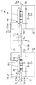
- the drawing schematically shows a treatment device 11 for plate-shaped objects 17, for example electrical circuit boards, ie insulating plastic plates which are usually provided on both sides with conductor tracks.
- the circuit boards shown quite thick in the schematic representation are in reality usually very thin, for example in the range of 25 ⁇ m or less. Accordingly, they are very flexible.
- the device 11 has two treatment stations which consist of elongated containers through which a transport device 15 runs along a horizontal transport plane 33. It also includes a turning station 14 provided between the two treatment stations.
- the transport device At its entrance and exit from each treatment station, the transport device has 12 lower belts 16 on which the object 17 is transported. These lower belts transfer the object to upper belts 18, which belong to a suction transport device 19.
- a suction box 20 is provided between the upper and lower run of the upper belts. It has suction openings 32 on its underside, through which the lower run of the possibly perforated upper band runs.
- the suction box is connected to a vacuum pump 22 via vacuum lines 21. Possibly. is still a liquid separator, not shown, e.g. a cyclone separator, interposed.
- the upper bands 18 extend over the entire length of the treatment area of each treatment station. Like the lower belts 16, they are driven.
- 33 spray nozzles 29 are arranged under the transport plane, which, viewed in the transport direction 34, are arranged in a row in several rows. They are supplied by a pump 28 with treatment medium which forms a sump in the container belonging to the treatment station.
- the treatment medium is a liquid, preferably for etching the coated printed circuit boards.
- other treatment media could be used.
- the advantages are particularly noticeable in treatments in which chemical or physical treatment takes place that is dependent on time and flushing intensity.
- spraying the liquid on it could also be brought to the object in other ways, for example in the form of gushing sections.
- a number of gushing sections could be connected in series in a treatment station 12, so that liquid can run off or drip off in between.
- the turning station 14 has synchronously driven upper and lower belts which, if necessary, only grasp the object at its edge. These belts, which clamp the object between them, can be pivoted about a turning axis 23. This could be perpendicular to the plane of the drawing, i.e. run horizontally and transversely to the transport direction 34. If it is desired to swap the top and bottom sides of the object 17 in the turning station, but also to turn them about a vertical axis, the turning axis 23 could, as indicated, be inclined, e.g. inclined at 45 ° to the plane of the drawing, but lying in the transport plane.
- the objects 17 run into the first treatment station 12 in the transport plane 33, which is formed at the inlet 25 by the upper side of the lower belts 16. Before the actual treatment area begins, they are removed from the Suction transport device 19 taken over, wherein rollers 35 arranged in front of and behind the upper belt support the transfer.
- the vacuum pump 22 continuously sucks air from the suction box 20 via the vacuum lines 21, which flows into the suction box 32.
- the perforated upper band 18 lies above the suction openings 32. However, it is also possible to provide the suction openings 32 parallel to non-perforated, relatively narrow upper bands.
- the treatment liquid is applied from below onto the object which is now suspended with a free underside. It can drip off immediately behind the nozzle, so that fresh treatment liquid is applied several times if there are several rows of nozzles arranged one after the other.
- the suction sections e.g. the number of holes and / or diameter of the perforations of the suction box at the location opposite each nozzle or row of nozzles are reduced or omitted entirely.
- Treatment liquid sucked into the suction box is separated from the suction air there and / or in the downstream liquid separator and returned to the circuit.
- the object runs into the turning station 14, which guides the object with its driven conveyor belts 24 and at the same time actively transports it.
- the turning station is rotated about the turning axis 23, so that the object with the previously treated side now ends up on the lower conveyor belt 16 of the second treatment station 13.
- the treatment cycle for the other side of the object 17 is carried out, also from below.
Abstract
Description
Die Erfindung betrifft ein Verfahren und eine Vorrichtung zum Behandeln von plattenförmigen Gegenständen mit einem flüssigen Medium, insbesondere zum Ätzen von Leiterplatten.The invention relates to a method and a device for treating plate-shaped objects with a liquid medium, in particular for etching printed circuit boards.
Aus der EP-504 656 A1 ist ein solches Verfahren und eine solche Vorrichtung bekanntgeworden. Die Behandlung der zu ätzenden Leiterplatten von der Unterseite ermöglicht ein sehr schnelles und wirksames Ätzen, weil die aufgebrachte Flüssigkeit unmittelbar nach ihrer Einwirkung wieder von der Oberfläche abtropfen kann und keine "Pfützen" gebildet werden, in denen eine verzögerte Reaktion auftreten könnte. Die Leiterplatten werden auf Rollenbahnen durch die Behandlungsstation geführt, durch die hindurch das Behandlungsmedium aufgebracht wird, beispielsweise durch Sprühen. Oberbänder laufen parallel zur Transportebene und verhindern ein Ausweichen der Leiterplatten nach oben.Such a method and such a device have become known from EP-504 656 A1. The treatment of the printed circuit boards to be etched from the underside enables a very quick and effective etching because the liquid applied can drip off the surface immediately after its action and no "puddles" are formed in which a delayed reaction could occur. The circuit boards are guided on roller conveyors through the treatment station, through which the treatment medium is applied, for example by spraying. Top bands run parallel to the transport level and prevent the PCBs from moving upwards.
Dieses Verfahren arbeitet mit üblichen Leiterplatten ausreichender Dicke und Steifigkeit gut und störungsfrei.This method works well and trouble-free with conventional circuit boards of sufficient thickness and rigidity.
Aufgabe der Erfindung ist es, das Verfahren und die Vorrichtung der beschriebenen Art so weiterzuentwickeln, daß es auch bei extrem dünnen und flexiblen Gegenständen einsetzbar ist.The object of the invention is to further develop the method and the device of the type described so that it can also be used with extremely thin and flexible objects.
Diese Aufgabe wird durch die Ansprüche 1 und 5 gelöst.This object is solved by claims 1 and 5.
Der durch die Saugwirkung erzielte hängende Transport ermöglicht die Lösung zweier Probleme: Sehr dünne und sehr flexible Gegenstände, beispielsweise Leiterplatten, die bis zu einer Minimaldicke von 25 µm oder darunter verarbeitet werden, neigen dazu, auf Rollenbahnen abgelenkt zu werden und zwischen benachbarte Rollen zu geraten, was zu ernsthaften Betriebsstörungen führt. Eine Abhilfe könnte hier nur eine immer dichtere Anordnung der in Transportrichtung aufeinanderfolgenden Rollen bringen. Teilweise müßten diese sich sogar überlappen, um keine Spalte für das Ausweichen der Leiterplatten von der Transportebene zu eröffnen. Durch den Saugtransport kann auf die Rollenbahnen ganz verzichtet werden. Der Gegenstand ist von seiner Oberseite her gehalten und hat keine Möglichkeit, von dem Förderband, gegen das ihn die Saugwirkung ansaugt, woandershin abzuweichen.The hanging transport achieved by the suction effect enables two problems to be solved: Very thin and very flexible objects, for example printed circuit boards, which are processed to a minimum thickness of 25 µm or less, tend to be deflected on roller conveyors and to get between adjacent rollers , which leads to serious malfunctions. A remedy here could only be an increasingly dense arrangement of the successive rollers in the transport direction. In some cases, these would even have to overlap so as not to open any gaps for the circuit boards to move away from the transport level. The roller conveyors can be dispensed with entirely thanks to the suction transport. The object is held from its top and has no possibility to deviate elsewhere from the conveyor belt against which the suction effect sucks it.
Zugleich wird ein weiteres großes Problem gelöst, das bei der Behandlung von Gegenständen mit dem Medium von unten her auftrat, nämlich die Tatsache, daß zwischen den die Gegenstände leitenden Rollenbahnen die Behandlung z.B. durch Sprühen von unten behindert wurde. Nunmehr ist der Gegenstand vollständig frei zugänglich, so daß er beliebig von seiner Unterseite behandelt werden kann.At the same time, another major problem is solved that occurred when treating objects with the medium from below, namely the fact that between the roller conveyors that conduct the objects, the treatment, for example, by Spraying from below was hindered. Now the object is completely freely accessible so that it can be treated from its underside as desired.
Vorzugsweise werden beide Seiten des Gegenstandes von der Unterseite her behandelt, um das Behandlungsmedium stets frisch aufzubringen und es danach sofort abtropfen zu lassen. Dadurch wird das Behandlungsmedium stets frisch aufgebracht. Es können keine "Pfützen" entstehen, die zu einer ungleichmäßigen Behandlung führen würden. Ferner wird durch die gezielte Entfernung des Mediums durch Abfließen und/oder Abtropfen unmittelbar nach der Aufbringung die Bildung einer Schicht verbrauchten Mediums verhindert, und das vorzugsweise wiederholt neue Aufbringen von Medium in aufeinanderfolgenden Aufbringungsbereichen führt zu einer hohen Turbulenz in der Grenzschicht und dadurch zu erhöhter Reaktionsgeschwindigkeit und -gleichmäßigkeit.Both sides of the object are preferably treated from the underside in order to always apply the treatment medium freshly and then to let it drip off immediately. As a result, the treatment medium is always applied freshly. There can be no "puddles" that would lead to uneven treatment. Furthermore, the targeted removal of the medium by draining and / or dripping immediately after application prevents the formation of a layer of used medium, and the preferably repeated application of medium in successive application areas leads to high turbulence in the boundary layer and thus to increased reaction speed and uniformity.
Es können beispielsweise mehrere aufeinanderfolgende Reihen von Sprühdüsen vorgesehen sein, zwischen denen das Medium jeweils abfließen und/oder abtropfen kann. Die Vorrichtung kann beispielsweise ein gelochtes Förderband aufweisen, an dessen Untertrum die Gegenstände durch einen Saugkasten angesaugt werden, der mit einer Vakuumpumpe sowie ggf. mit zwischengeschaltetem Abscheider für das Medium, verbunden ist.For example, several successive rows of spray nozzles can be provided, between which the medium can each flow off and / or drip off. The device can, for example, have a perforated conveyor belt, on the lower run of which the objects are sucked through a suction box, which is connected to a vacuum pump and, if appropriate, to an intermediate separator for the medium.
Um die Behandlung beider Seiten des Gegenstandes jeweils von der Unterseite her sicherzustellen, kann zwischen zwei aufeinanderfolgenden Behandlungsstationen eine Wendestation eingeschaltet sein. Es ist aber auch möglich, eine Wendestation am Auslauf nur einer Behandlungsstation vorzusehen, die Gegenstände darin um 180° zu drehen und sie in umgekehrter Transportrichtung wieder zurücklaufen zu lassen. Einzelheiten dieser doppelseitigen Behandlung jeweils von unten her sind der EP-504 656 A1 zu entnehmen, auf die hier ausdrücklich Bezug genommen wird.In order to ensure the treatment of both sides of the object from the underside, a turning station can be switched on between two successive treatment stations. However, it is also possible to provide a turning station at the outlet of only one treatment station, to rotate the objects therein by 180 ° and to let them run back again in the opposite direction of transport. details This double-sided treatment from below can be found in EP-504 656 A1, to which reference is expressly made here.
Diese und weitere Merkmale gehen außer aus den Ansprüchen auch aus der Beschreibung und den Zeichnungen hervor, wobei die einzelnen Merkmale jeweils für sich allein oder zu mehreren in Form von Unterkombinationen bei einer Ausführungsform der Erfindung und auf anderen Gebieten verwirklicht sein und vorteilhafte sowie für sich schutzfähige Ausführungen darstellen können, für die hier Schutz beansprucht wird.These and further features emerge from the claims and also from the description and the drawings, the individual features being realized individually or in groups in the form of sub-combinations in one embodiment of the invention and in other fields and being advantageous and capable of being protected by themselves Can represent versions for which protection is claimed here.
Die Unterteilung der Anmeldung in einzelne Abschnitte sowie Zwischen-Überschriften beschränken die unter diesen gemachten Aussagen nicht in ihrer Allgemeingültigkeit.The division of the application into individual sections and subheadings do not limit the general validity of the statements made under these.
Ein Ausführungsbeispiel der Erfindung ist in den Zeichnungen dargestellt und wird im folgenden näher erläutert. Die einzige
Zeichnungsfigur zeigt einen schematischen Längsschnitt durch eine Behandlungsvorrichtung.An embodiment of the invention is shown in the drawings and is explained in more detail below. The only
Drawing figure shows a schematic longitudinal section through a treatment device.
Die Zeichnung zeigt schematisch eine Behandlungsvorrichtung 11 für plattenförmige Gegenstände 17, beispielsweise elektrische Leiterplatten, d.h. mit Leiterbahnen meist auf beiden Seiten zu versehende isolierende Kunststoffplättchen. Die in der schematischen Darstellung recht dick gezeigten Leiterplatten sind in Wirklichkeit meist sehr dünn, z.B. im Bereich von 25 µm oder darunter. Dementsprechend sind sie sehr biegeweich.The drawing schematically shows a
Die Vorrichtung 11 weist zwei Behandlungsstationen auf, die aus langgestreckten Behältern bestehen, durch die längs einer horizontalen Transportebene 33 eine Transportvorrichtung 15 verläuft. Zu ihr gehört auch eine zwischen beiden Behandlungsstationen vorgesehene Wendestation 14.The
Die Transportvorrichtung weist an ihrem Eingang und Ausgang aus jeder Behandlungsstation 12 Unterbänder 16 auf, auf denen der Gegenstand 17 transportiert wird. Diese Unterbänder übergeben den Gegenstand an darüber angeordnete Oberbänder 18, die zu einer Saugtransporteinrichtung 19 gehören.At its entrance and exit from each treatment station, the transport device has 12 lower belts 16 on which the
Ein Saugkasten 20 ist zwischen Ober- und Untertrum der Oberbänder vorgesehen. Er weist Saugöffnungen 32 an seiner Unterseite auf, über die das untere Trum des ggf. gelochten Oberbands läuft. Der Saugkasten ist über Vakuumleitungen 21 mit einer Vakuumpumpe 22 verbunden. Ggf. ist noch ein nicht dargestellter Flüssigkeitsabscheiderj, z.B. ein Zyklonabscheider, zwischengeschaltet.A
Die Oberbänder 18 erstrecken sich über die gesamte Länge des Behandlungsbereiches jeder Behandlungsstation. Sie sind, ebenso wie die Unterbänder 16, angetrieben.The
Im Behandlungsbereich sind unter der Transportebene 33 Sprühdüsen 29 angeordnet, die, in Transportrichtung 34 gesehen, in mehreren Reihen hintereinander liegen. Sie werden von einer Pumpe 28 mit Behandlungsmedium versorgt, das in dem zur Behandlungsstation gehörenden Behälter einen Sumpf bildet.In the treatment area, 33
Bei dem Behandlungsmedium handelt es sich um eine Flüssigkeit, bevorzugt zum Ätzen der beschichteten Leiterplatten. Es könnten jedoch auch andere Behandlungsmedien verwendet werden. Die Vorteile kommen allerdings besonders bei Behandlungen zur Geltung, bei denen eine von Zeit und Spülungsintensität abhängige chemische oder physikalische Behandlung stattfindet. Statt des Aufsprühens der Flüssigkeit könnte sie auch auf andere Weise an den Gegenstand herangebracht werden, beispielsweise in Form von Schwallstrecken. Hier könnten in einer Behandlungsstation 12 mehrere Schwallstrecken hintereinandergeschaltet sein, so daß zwischendrin Flüssigkeit wieder ablaufen oder abtropfen kann.The treatment medium is a liquid, preferably for etching the coated printed circuit boards. However, other treatment media could be used. However, the advantages are particularly noticeable in treatments in which chemical or physical treatment takes place that is dependent on time and flushing intensity. Instead of spraying the liquid on, it could also be brought to the object in other ways, for example in the form of gushing sections. Here, a number of gushing sections could be connected in series in a
Die Wendestation 14 besitzt synchron angetriebene Ober- und Unterbänder, die ggf. den Gegenstand auch nur an seinem Rand erfassen. Diese Bänder, die den Gegenstand zwischen sich einspannen, können um eine Wendeachse 23 geschwenkt werden. Diese könnte senkrecht zur Zeichenebene, d.h. horizontal und quer zur Transportrichtung 34, verlaufen. Wenn es erwünscht ist, bei dem Gegenstand 17 zwar Ober- und Unterseite in der Wendestation zu vertauschen, jedoch sie auch um eine vertikale Achse zu drehen, so könnte die Wendeachse 23 auch, wie angedeutet, schräg, z.B. unter 45° zur Zeichenebene geneigt, jedoch in der Transportebene liegend, angeordnet sein.The
Die Gegenstände 17 laufen in der Transportebene 33, die am Einlauf 25 von der Oberseite der Unterbänder 16 gebildet wird, in die erste Behandlungsstation 12 ein. Bevor der eigentliche Behandlungsbereich beginnt, werden sie von der Saugtransporteinrichtung 19 übernommen, wobei vor und hinter dem Oberband angeordnete Rollen 35 die Überleitung unterstützen.The
Die Vakuumpumpe 22 saugt über die Vakuumleitungen 21 ständig Luft aus dem Saugkasten 20, die durch die Saugöffnungen 32 in diesen einströmt. Über den Saugöffnungen 32 liegt das gelochte Oberband 18. Es ist aber auch möglich, die Saugöffnungen 32 parallel zu ungelochten, relativ schmalen Oberbändern vorzusehen.The
Durch die Sprühdüsen 29 wird die Behandlungsflüssigkeit von unten auf den nunmehr mit freier Unterseite hängend geförderten Gegenstand aufgebracht. Sie kann jeweils sofort hinter der Düse wieder abtropfen, so daß bei mehreren ggf. in Gruppen hintereinander angeordneten Düsenreihen mehrfach frische Behandlungsflüssigkeit aufgebracht wird.By means of the
Um ein Einsaugen von Behandlungsflüssigkeit in den Saugkasten zu reduzieren, könnten die Saugstrecken, z.B. die Lochungen des Saugkastens, an den jeweils einer Düse oder Düsenreihe gegenüberliegenden Stelle in Zahl und/oder Durchmesser reduziert oder gänzlich weggelassen werden.In order to reduce the suction of treatment liquid in the suction box, the suction sections, e.g. the number of holes and / or diameter of the perforations of the suction box at the location opposite each nozzle or row of nozzles are reduced or omitted entirely.
In den Saugkasten eingesaugte Behandlungsflüssigkeit wird dort und/oder in dem nachgeschalteten Flüssigkeitsabscheider von der Saugluft abgesondert und in den Kreislauf zurückgeführt.Treatment liquid sucked into the suction box is separated from the suction air there and / or in the downstream liquid separator and returned to the circuit.
Da der Saugkasten nur das Untertrum zwischen den beiden Umlenkrollen des Oberbandes erfaßt, endet die Saugwirkung wieder vor dem Auslauf 26, wo der Gegenstand wieder auf ein Unterband 16 übergeben wird.Since the suction box only detects the lower run between the two deflection rollers of the upper belt, the suction effect ends again before the
Von da läuft der Gegenstand in die Wendestation 14, die mit ihren angetriebenen Förderbändern 24 den Gegenstand führt und gleichzeitig aktiv transportiert. Wenn der Gegenstand ganz zwischen den Förderbändern 24 aufgenommen ist, wird die Wendestation um die Wendeachse 23 gedreht, so daß der Gegenstand nun mit der vorher behandelten Seite obenliegend auf das Einlauf-Unterband 16 der zweiten Behandlungsstation 13 gelangt. Dort wird der Behandlungszyklus für die andere Seite des Gegenstandes 17, ebenfalls von unten, durchgeführt.From there, the object runs into the turning
Claims (10)
Applications Claiming Priority (2)
| Application Number | Priority Date | Filing Date | Title |
|---|---|---|---|
| DE19509313 | 1995-03-15 | ||
| DE19509313A DE19509313A1 (en) | 1995-03-15 | 1995-03-15 | Method and device for treating plate-shaped objects, in particular printed circuit boards |
Publications (2)
| Publication Number | Publication Date |
|---|---|
| EP0732424A1 true EP0732424A1 (en) | 1996-09-18 |
| EP0732424B1 EP0732424B1 (en) | 1999-06-30 |
Family
ID=7756700
Family Applications (1)
| Application Number | Title | Priority Date | Filing Date |
|---|---|---|---|
| EP96103716A Expired - Lifetime EP0732424B1 (en) | 1995-03-15 | 1996-03-09 | Method and apparatus for treating plate like articles, in particular printed circuit boards |
Country Status (3)
| Country | Link |
|---|---|
| EP (1) | EP0732424B1 (en) |
| DE (2) | DE19509313A1 (en) |
| ES (1) | ES2135807T3 (en) |
Cited By (7)
| Publication number | Priority date | Publication date | Assignee | Title |
|---|---|---|---|---|
| US6174417B1 (en) | 1998-05-20 | 2001-01-16 | Process Automation International Ltd. | Electroplating machine |
| US6261425B1 (en) | 1998-08-28 | 2001-07-17 | Process Automation International, Ltd. | Electroplating machine |
| ITUD20090045A1 (en) * | 2009-02-23 | 2010-08-24 | Applied Materials Inc | SUBSTRATE SUPPORT MATERIAL IMPROVED USEFUL FOR PRINTING PRINTING PROCEDURES |
| ITMO20110009A1 (en) * | 2011-01-21 | 2012-07-22 | Airone S R L | POTS PAINTING SYSTEM. |
| CN102916075A (en) * | 2012-09-27 | 2013-02-06 | 奥特斯维能源(太仓)有限公司 | Method for stabilizing wool-making depth |
| CN108097502A (en) * | 2018-01-04 | 2018-06-01 | 海宁德阳高分子材料科技有限公司 | A kind of high physical property can emboss dry method environmental protection sofa artificial leather production anti-corrosive apparatus |
| CN110055577A (en) * | 2019-05-07 | 2019-07-26 | 重庆平伟实业股份有限公司 | A kind of electroplanting device and method of axial lead electronic component |
Families Citing this family (4)
| Publication number | Priority date | Publication date | Assignee | Title |
|---|---|---|---|---|
| DE19645760A1 (en) * | 1996-11-06 | 1998-05-07 | Schmid Gmbh & Co Geb | Method and device for generating a defined current of horizontally guided printed circuit boards |
| DE19930207C2 (en) * | 1999-06-22 | 2001-12-06 | Schulz Harder Juergen | Process for the production of substrates with structured metallizations and holding and fixing element for use in this process |
| EP1063873A3 (en) | 1999-06-22 | 2003-04-23 | Dr.-Ing. Jürgen Schulz-Harder | Process for manufacturing substrates with patterned metallizations and holding and fixing element used in the process |
| DE10154884C5 (en) * | 2001-11-05 | 2009-11-19 | Gebr. Schmid Gmbh & Co. | Device for transporting flexible flat material, in particular printed circuit boards |
Citations (7)
| Publication number | Priority date | Publication date | Assignee | Title |
|---|---|---|---|---|
| DE2937388A1 (en) * | 1979-09-15 | 1981-04-16 | Hugo 6419 Eiterfeld Isert | Appts. for treatment of printed circuit boards or coated panels - using row of narrow chambers requiring min. amt. of treatment liquids |
| US4339297A (en) * | 1981-04-14 | 1982-07-13 | Seiichiro Aigo | Apparatus for etching of oxide film on semiconductor wafer |
| DE3602078A1 (en) * | 1986-01-24 | 1987-07-30 | Riba Prueftechnik Gmbh | Holding device, in particular for circuit boards |
| EP0267874A1 (en) * | 1986-11-10 | 1988-05-18 | Haas-Laser Systems AG | Method of conveying of flat perforated articles |
| EP0269566A1 (en) * | 1986-11-10 | 1988-06-01 | Haas-Laser Systems AG | Conveyor device for flat perforated articles |
| US4759817A (en) * | 1986-05-15 | 1988-07-26 | Seiichiro Aigo | Apparatus for etching semiconductor material |
| EP0498250A1 (en) * | 1991-02-05 | 1992-08-12 | International Business Machines Corporation | Etching method for increased circuitized line width unitformity |
-
1995
- 1995-03-15 DE DE19509313A patent/DE19509313A1/en not_active Withdrawn
-
1996
- 1996-03-09 DE DE59602307T patent/DE59602307D1/en not_active Expired - Lifetime
- 1996-03-09 EP EP96103716A patent/EP0732424B1/en not_active Expired - Lifetime
- 1996-03-09 ES ES96103716T patent/ES2135807T3/en not_active Expired - Lifetime
Patent Citations (7)
| Publication number | Priority date | Publication date | Assignee | Title |
|---|---|---|---|---|
| DE2937388A1 (en) * | 1979-09-15 | 1981-04-16 | Hugo 6419 Eiterfeld Isert | Appts. for treatment of printed circuit boards or coated panels - using row of narrow chambers requiring min. amt. of treatment liquids |
| US4339297A (en) * | 1981-04-14 | 1982-07-13 | Seiichiro Aigo | Apparatus for etching of oxide film on semiconductor wafer |
| DE3602078A1 (en) * | 1986-01-24 | 1987-07-30 | Riba Prueftechnik Gmbh | Holding device, in particular for circuit boards |
| US4759817A (en) * | 1986-05-15 | 1988-07-26 | Seiichiro Aigo | Apparatus for etching semiconductor material |
| EP0267874A1 (en) * | 1986-11-10 | 1988-05-18 | Haas-Laser Systems AG | Method of conveying of flat perforated articles |
| EP0269566A1 (en) * | 1986-11-10 | 1988-06-01 | Haas-Laser Systems AG | Conveyor device for flat perforated articles |
| EP0498250A1 (en) * | 1991-02-05 | 1992-08-12 | International Business Machines Corporation | Etching method for increased circuitized line width unitformity |
Non-Patent Citations (2)
| Title |
|---|
| FIGULI E. S.: "Wafer plating fixture", WESTERN ELECTRIC TECHNICAL DIGEST, no. 30, 1 April 1973 (1973-04-01), pages 9 - 10, XP002007210 * |
| KELLER: "Ultrasonic fountain processor", IBM TECHNICAL DISCLOSURE BULLETIN, vol. 10, no. 5, 1 October 1967 (1967-10-01), NEW YORK US, pages 528 - 529, XP002007209 * |
Cited By (11)
| Publication number | Priority date | Publication date | Assignee | Title |
|---|---|---|---|---|
| US6174417B1 (en) | 1998-05-20 | 2001-01-16 | Process Automation International Ltd. | Electroplating machine |
| US6241860B1 (en) | 1998-05-20 | 2001-06-05 | Process Automation International, Ltd. | Electroplating machine |
| US6251234B1 (en) | 1998-05-20 | 2001-06-26 | Process Automation International, Ltd. | Electroplating machine |
| US6261425B1 (en) | 1998-08-28 | 2001-07-17 | Process Automation International, Ltd. | Electroplating machine |
| ITUD20090045A1 (en) * | 2009-02-23 | 2010-08-24 | Applied Materials Inc | SUBSTRATE SUPPORT MATERIAL IMPROVED USEFUL FOR PRINTING PRINTING PROCEDURES |
| WO2010094347A1 (en) * | 2009-02-23 | 2010-08-26 | Applied Materials, Inc. | Improved substrate support material useful for screen printing processes |
| ITMO20110009A1 (en) * | 2011-01-21 | 2012-07-22 | Airone S R L | POTS PAINTING SYSTEM. |
| CN102916075A (en) * | 2012-09-27 | 2013-02-06 | 奥特斯维能源(太仓)有限公司 | Method for stabilizing wool-making depth |
| CN108097502A (en) * | 2018-01-04 | 2018-06-01 | 海宁德阳高分子材料科技有限公司 | A kind of high physical property can emboss dry method environmental protection sofa artificial leather production anti-corrosive apparatus |
| CN110055577A (en) * | 2019-05-07 | 2019-07-26 | 重庆平伟实业股份有限公司 | A kind of electroplanting device and method of axial lead electronic component |
| CN110055577B (en) * | 2019-05-07 | 2021-03-12 | 重庆平伟实业股份有限公司 | Electroplating device and method for axial lead electronic component |
Also Published As
| Publication number | Publication date |
|---|---|
| DE19509313A1 (en) | 1996-09-19 |
| DE59602307D1 (en) | 1999-08-05 |
| EP0732424B1 (en) | 1999-06-30 |
| ES2135807T3 (en) | 1999-11-01 |
Similar Documents
| Publication | Publication Date | Title |
|---|---|---|
| EP0427053B1 (en) | Device and method for coating printed circuit plates | |
| DE69729578T2 (en) | LIQUID DISPENSER AND METHOD | |
| DE4121032A1 (en) | DEVICE FOR TREATING PLATE-SHAPED OBJECTS, IN PARTICULAR BOARDS | |
| DE102007063202A1 (en) | Method and apparatus for treating silicon wafers | |
| DE2320199B2 (en) | Method and apparatus for cleaning printed circuit boards | |
| DE4107224C1 (en) | ||
| EP0732424A1 (en) | Method and apparatus for heating plate like articles, in particular printed circuit boards | |
| AT401133B (en) | METHOD FOR TREATING PIECE-SHAPED PARTS IN CONTINUOUS PLANTS, AND DEVICE FOR CARRYING OUT THIS METHOD | |
| DE1961782A1 (en) | Method and device for treating textile material webs | |
| DE3721404C2 (en) | ||
| DE112015005723T5 (en) | NOZZLE HEAD AND DEVICE FOR COATING A CARRIER SURFACE | |
| DE10039558A1 (en) | Device for spray treatment of printed circuit boards uses conveyor devices to convey printed circuit boards on a horizontally aligned printed circuit board level and a nozzle device for spraying the top side of printed circuit boards. | |
| EP1442646B1 (en) | Device for the transport of flexible planar material, in particular circuit boards | |
| EP0970899B1 (en) | Method and device for processing slice-shaped articles like plates, panes of glass, circuit boards, ceramic substrates | |
| DE3026176C2 (en) | Tunnel furnace for the production of plate-like flat structures coated on both sides with a curable material, in particular printed circuit boards | |
| EP0399325A1 (en) | Arrangement for treating and/or cleaning of products, especially of printed circuit panels provided with borings | |
| DE3817543A1 (en) | MACHINE FOR TREATING OBJECTS WITH A TREATMENT LIQUID | |
| EP0441743A1 (en) | Transfer device for plates with sensitive surface, particularly for wet coated printed circuits | |
| EP0752277A2 (en) | Apparatus for heating flexible plate-foil like articles, in particular printed circuit boards | |
| DE60300039T2 (en) | Singulation conveyor system | |
| EP2006029B1 (en) | Device for applying an application to a substrate | |
| DE4221994C2 (en) | Device for treating photographic substrates | |
| DE102004040945B4 (en) | Method and device for selective coating of printed circuit boards | |
| WO2016202501A1 (en) | Method for electrically treating a film and device for said method | |
| DE4223542A1 (en) | Circuit board processing appts. with processing liq. - has nozzle sticks carrying processing fluid with distributor tube connected to multiple nozzle bodies with slit-shaped openings |
Legal Events
| Date | Code | Title | Description |
|---|---|---|---|
| PUAI | Public reference made under article 153(3) epc to a published international application that has entered the european phase |
Free format text: ORIGINAL CODE: 0009012 |
|
| AK | Designated contracting states |
Kind code of ref document: A1 Designated state(s): DE ES FR GB IT SE |
|
| 17P | Request for examination filed |
Effective date: 19960925 |
|
| 17Q | First examination report despatched |
Effective date: 19970613 |
|
| GRAG | Despatch of communication of intention to grant |
Free format text: ORIGINAL CODE: EPIDOS AGRA |
|
| GRAG | Despatch of communication of intention to grant |
Free format text: ORIGINAL CODE: EPIDOS AGRA |
|
| GRAH | Despatch of communication of intention to grant a patent |
Free format text: ORIGINAL CODE: EPIDOS IGRA |
|
| GRAH | Despatch of communication of intention to grant a patent |
Free format text: ORIGINAL CODE: EPIDOS IGRA |
|
| GRAA | (expected) grant |
Free format text: ORIGINAL CODE: 0009210 |
|
| AK | Designated contracting states |
Kind code of ref document: B1 Designated state(s): DE ES FR GB IT SE |
|
| ET | Fr: translation filed | ||
| GBT | Gb: translation of ep patent filed (gb section 77(6)(a)/1977) |
Effective date: 19990714 |
|
| REF | Corresponds to: |
Ref document number: 59602307 Country of ref document: DE Date of ref document: 19990805 |
|
| ITF | It: translation for a ep patent filed |
Owner name: ORGANIZZAZIONE D'AGOSTINI |
|
| REG | Reference to a national code |
Ref country code: ES Ref legal event code: FG2A Ref document number: 2135807 Country of ref document: ES Kind code of ref document: T3 |
|
| PLBE | No opposition filed within time limit |
Free format text: ORIGINAL CODE: 0009261 |
|
| STAA | Information on the status of an ep patent application or granted ep patent |
Free format text: STATUS: NO OPPOSITION FILED WITHIN TIME LIMIT |
|
| 26N | No opposition filed | ||
| REG | Reference to a national code |
Ref country code: GB Ref legal event code: IF02 |
|
| PGFP | Annual fee paid to national office [announced via postgrant information from national office to epo] |
Ref country code: GB Payment date: 20030224 Year of fee payment: 8 |
|
| PGFP | Annual fee paid to national office [announced via postgrant information from national office to epo] |
Ref country code: FR Payment date: 20030318 Year of fee payment: 8 |
|
| PGFP | Annual fee paid to national office [announced via postgrant information from national office to epo] |
Ref country code: SE Payment date: 20030324 Year of fee payment: 8 |
|
| PG25 | Lapsed in a contracting state [announced via postgrant information from national office to epo] |
Ref country code: GB Free format text: LAPSE BECAUSE OF NON-PAYMENT OF DUE FEES Effective date: 20040309 |
|
| PG25 | Lapsed in a contracting state [announced via postgrant information from national office to epo] |
Ref country code: SE Free format text: LAPSE BECAUSE OF NON-PAYMENT OF DUE FEES Effective date: 20040310 |
|
| GBPC | Gb: european patent ceased through non-payment of renewal fee | ||
| EUG | Se: european patent has lapsed | ||
| PG25 | Lapsed in a contracting state [announced via postgrant information from national office to epo] |
Ref country code: FR Free format text: LAPSE BECAUSE OF NON-PAYMENT OF DUE FEES Effective date: 20041130 |
|
| REG | Reference to a national code |
Ref country code: FR Ref legal event code: ST |
|
| PGFP | Annual fee paid to national office [announced via postgrant information from national office to epo] |
Ref country code: ES Payment date: 20060320 Year of fee payment: 11 |
|
| PGFP | Annual fee paid to national office [announced via postgrant information from national office to epo] |
Ref country code: IT Payment date: 20060331 Year of fee payment: 11 |
|
| REG | Reference to a national code |
Ref country code: ES Ref legal event code: FD2A Effective date: 20070310 |
|
| PG25 | Lapsed in a contracting state [announced via postgrant information from national office to epo] |
Ref country code: ES Free format text: LAPSE BECAUSE OF NON-PAYMENT OF DUE FEES Effective date: 20070310 |
|
| PG25 | Lapsed in a contracting state [announced via postgrant information from national office to epo] |
Ref country code: IT Free format text: LAPSE BECAUSE OF NON-PAYMENT OF DUE FEES Effective date: 20070309 |
|
| PGFP | Annual fee paid to national office [announced via postgrant information from national office to epo] |
Ref country code: DE Payment date: 20110322 Year of fee payment: 16 |
|
| REG | Reference to a national code |
Ref country code: DE Ref legal event code: R119 Ref document number: 59602307 Country of ref document: DE Effective date: 20121002 |
|
| PG25 | Lapsed in a contracting state [announced via postgrant information from national office to epo] |
Ref country code: DE Free format text: LAPSE BECAUSE OF NON-PAYMENT OF DUE FEES Effective date: 20121002 |