EP0732308A1 - Sludge treatment tank and construction method thereof - Google Patents
Sludge treatment tank and construction method thereof Download PDFInfo
- Publication number
- EP0732308A1 EP0732308A1 EP96301573A EP96301573A EP0732308A1 EP 0732308 A1 EP0732308 A1 EP 0732308A1 EP 96301573 A EP96301573 A EP 96301573A EP 96301573 A EP96301573 A EP 96301573A EP 0732308 A1 EP0732308 A1 EP 0732308A1
- Authority
- EP
- European Patent Office
- Prior art keywords
- sludge treatment
- treatment tank
- concrete
- tank
- formworks
- Prior art date
- Legal status (The legal status is an assumption and is not a legal conclusion. Google has not performed a legal analysis and makes no representation as to the accuracy of the status listed.)
- Granted
Links
Images


Classifications
-
- C—CHEMISTRY; METALLURGY
- C02—TREATMENT OF WATER, WASTE WATER, SEWAGE, OR SLUDGE
- C02F—TREATMENT OF WATER, WASTE WATER, SEWAGE, OR SLUDGE
- C02F11/00—Treatment of sludge; Devices therefor
-
- B—PERFORMING OPERATIONS; TRANSPORTING
- B29—WORKING OF PLASTICS; WORKING OF SUBSTANCES IN A PLASTIC STATE IN GENERAL
- B29C—SHAPING OR JOINING OF PLASTICS; SHAPING OF MATERIAL IN A PLASTIC STATE, NOT OTHERWISE PROVIDED FOR; AFTER-TREATMENT OF THE SHAPED PRODUCTS, e.g. REPAIRING
- B29C70/00—Shaping composites, i.e. plastics material comprising reinforcements, fillers or preformed parts, e.g. inserts
-
- B—PERFORMING OPERATIONS; TRANSPORTING
- B32—LAYERED PRODUCTS
- B32B—LAYERED PRODUCTS, i.e. PRODUCTS BUILT-UP OF STRATA OF FLAT OR NON-FLAT, e.g. CELLULAR OR HONEYCOMB, FORM
- B32B33/00—Layered products characterised by particular properties or particular surface features, e.g. particular surface coatings; Layered products designed for particular purposes not covered by another single class
-
- C—CHEMISTRY; METALLURGY
- C12—BIOCHEMISTRY; BEER; SPIRITS; WINE; VINEGAR; MICROBIOLOGY; ENZYMOLOGY; MUTATION OR GENETIC ENGINEERING
- C12M—APPARATUS FOR ENZYMOLOGY OR MICROBIOLOGY; APPARATUS FOR CULTURING MICROORGANISMS FOR PRODUCING BIOMASS, FOR GROWING CELLS OR FOR OBTAINING FERMENTATION OR METABOLIC PRODUCTS, i.e. BIOREACTORS OR FERMENTERS
- C12M21/00—Bioreactors or fermenters specially adapted for specific uses
- C12M21/04—Bioreactors or fermenters specially adapted for specific uses for producing gas, e.g. biogas
-
- C—CHEMISTRY; METALLURGY
- C12—BIOCHEMISTRY; BEER; SPIRITS; WINE; VINEGAR; MICROBIOLOGY; ENZYMOLOGY; MUTATION OR GENETIC ENGINEERING
- C12M—APPARATUS FOR ENZYMOLOGY OR MICROBIOLOGY; APPARATUS FOR CULTURING MICROORGANISMS FOR PRODUCING BIOMASS, FOR GROWING CELLS OR FOR OBTAINING FERMENTATION OR METABOLIC PRODUCTS, i.e. BIOREACTORS OR FERMENTERS
- C12M23/00—Constructional details, e.g. recesses, hinges
- C12M23/20—Material Coatings
-
- E—FIXED CONSTRUCTIONS
- E03—WATER SUPPLY; SEWERAGE
- E03F—SEWERS; CESSPOOLS
- E03F11/00—Cesspools
-
- E—FIXED CONSTRUCTIONS
- E04—BUILDING
- E04H—BUILDINGS OR LIKE STRUCTURES FOR PARTICULAR PURPOSES; SWIMMING OR SPLASH BATHS OR POOLS; MASTS; FENCING; TENTS OR CANOPIES, IN GENERAL
- E04H7/00—Construction or assembling of bulk storage containers employing civil engineering techniques in situ or off the site
- E04H7/02—Containers for fluids or gases; Supports therefor
- E04H7/18—Containers for fluids or gases; Supports therefor mainly of concrete, e.g. reinforced concrete, or other stone-like material
-
- B—PERFORMING OPERATIONS; TRANSPORTING
- B29—WORKING OF PLASTICS; WORKING OF SUBSTANCES IN A PLASTIC STATE IN GENERAL
- B29K—INDEXING SCHEME ASSOCIATED WITH SUBCLASSES B29B, B29C OR B29D, RELATING TO MOULDING MATERIALS OR TO MATERIALS FOR MOULDS, REINFORCEMENTS, FILLERS OR PREFORMED PARTS, e.g. INSERTS
- B29K2309/00—Use of inorganic materials not provided for in groups B29K2303/00 - B29K2307/00, as reinforcement
- B29K2309/08—Glass
-
- Y—GENERAL TAGGING OF NEW TECHNOLOGICAL DEVELOPMENTS; GENERAL TAGGING OF CROSS-SECTIONAL TECHNOLOGIES SPANNING OVER SEVERAL SECTIONS OF THE IPC; TECHNICAL SUBJECTS COVERED BY FORMER USPC CROSS-REFERENCE ART COLLECTIONS [XRACs] AND DIGESTS
- Y02—TECHNOLOGIES OR APPLICATIONS FOR MITIGATION OR ADAPTATION AGAINST CLIMATE CHANGE
- Y02A—TECHNOLOGIES FOR ADAPTATION TO CLIMATE CHANGE
- Y02A20/00—Water conservation; Efficient water supply; Efficient water use
- Y02A20/20—Controlling water pollution; Waste water treatment
- Y02A20/208—Off-grid powered water treatment
-
- Y—GENERAL TAGGING OF NEW TECHNOLOGICAL DEVELOPMENTS; GENERAL TAGGING OF CROSS-SECTIONAL TECHNOLOGIES SPANNING OVER SEVERAL SECTIONS OF THE IPC; TECHNICAL SUBJECTS COVERED BY FORMER USPC CROSS-REFERENCE ART COLLECTIONS [XRACs] AND DIGESTS
- Y02—TECHNOLOGIES OR APPLICATIONS FOR MITIGATION OR ADAPTATION AGAINST CLIMATE CHANGE
- Y02E—REDUCTION OF GREENHOUSE GAS [GHG] EMISSIONS, RELATED TO ENERGY GENERATION, TRANSMISSION OR DISTRIBUTION
- Y02E50/00—Technologies for the production of fuel of non-fossil origin
- Y02E50/30—Fuel from waste, e.g. synthetic alcohol or diesel
Definitions
- the present invention relates to a sludge treatment tank and a construction method thereof, and more specifically, to a sludge treatment tank suitable for a biological reaction tank such as a digester tank and the like for the treatment of sludge in a sewage treatment plant and a construction method thereof.
- sludge contained in inflow sewage is separated from water by a sedimentation treatment or the like, organic substances contained in the separated sludge are removed as a gas by a biological reaction effected in a digester tank having an optimum temperature and the remaining sludge is disposed of by being dehydrated, dried and burnt.
- the organic gas taken out is used as an energy source by being burnt.
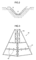
- Fig. 10 - Fig. 12 show these three types of the digester tanks, wherein Fig. 10 shows a tank having an egg-shaped, i.e. ovoid, longitudinal cross sectional shape, Fig. 11 shows a tank having a hexagon-shaped longitudinal cross sectional shape and Fig. 12 shows a tank having a flat longitudinal cross sectional shape.
- the flat tank formed to a cylindrical shape with a large diameter shown in Fig. 12 has a defect that it requires a large exclusive area, is disadvantageous in heat accumulation and operates at an expensive running cost.
- the egg-shaped tank shown in Fig. 10 makes sludge to smoothly circulate and flow, has a small exclusive area and operates at a low running cost because the tank can be easily insulated.
- the hexagon-shaped tank shown in Fig. 11 is somewhat inferior to the egg-shaped tank in performance, since it does not include such complex curves as used in the egg-shaped tank, it can be easily constructed. In Europe and the United States, a great many number of the egg-shaped tanks of Fig. 10 or the hexagon-shaped tanks of Fig. 11 are constructed.
- these digester tanks are constructed such that a corrosion preventing material 41 is coated on the inside wall of a reinforced concrete 40 and a heat insulator 42 and further a weather lining 43 is applied on the outside thereof.
- a corrosion preventing material 41 is coated on the inside wall of a reinforced concrete 40 and a heat insulator 42 and further a weather lining 43 is applied on the outside thereof.
- this construction method it is a usual practice that after reinforcing bars are fabricated, formworks are applied on the outside and the inside of the reinforcing bars and concrete is placed and a prestress is applied by high strength steel members. Further, the heat insulator is applied on the outside wall of the concrete for heat insulation and the weather lining is applied for finishing the outside of the concrete. Further, a corrosion preventing material is coated on the inside wall surface and thereafter machinery and equipment, pipings are installed in the tank.
- An aim of the present invention for solving the above problems is to provide a sludge treatment tank capable of realizing labor saving in working processes in a field of construction work, reduction of a period of construction work and working in a good environment as well as a method of constructing the sludge treatment tank in the construction of a biological reaction tank such as a digester tank and the like.
- the sludge treatment tank of the present invention comprises a concrete tank including a member composed of a glass long-fiber reinforced foamed plastic composite material as an inside wall material also serving as a formwork.
- a method of constructing a sludge treatment tank comprising the step of using a member composed of a glass long-fiber reinforced foamed plastic composite material as the inside formworks of inside and outside formworks used to place concrete to the concrete sludge treatment tank.
- the glass long-fiber reinforced foamed plastic composite material since the glass long-fiber reinforced foamed plastic composite material has strength similar to or greater than that of wood, it can be used as a formwork, thus the composite material can be used as an inside wall member also serving as the formwork. Moreover, since the composite material contains closed cells and has heat insulating property, it is effective as an insulating material. Further, since the composite material is composed of a plastic material, it has a corrosion preventing action because it does not have a water absorbing property and is resistant to acid and alkali.
- the composite material when used as an inside wall member also serving as a formwork, a heat insulator and a corrosion preventing material, inside scaffolds are not needed and an insulating work, weather lining work and inside wall surface corrosion preventing work can be omitted. Further, the interior of the tank can be kept to a good working environment by the omission of the corrosion preventing work.
- the above glass long-fiber reinforced foamed plastic composite material is light in weight and can be easily handled, labor can be saved and a working efficiency can be improved in a field work.
- a digester tank 1 of an embodiment according to the present invention includes a hexagon-shaped longitudinal cross section composed of a lower conical portion 3, a cylindrical sidewall portion 4 and an upper conical portion 5 supported by stakes 2.
- a tank wall 6 is composed of a reinforced concrete and applied with a prestress by high strength steel members 7.
- An outside wall is finished by placed concrete and an inside wall member 8 of the tank is formed of a glass long-fiber reinforced formed urethane (hereinafter, abbreviated as GFRU) composite material.
- GFRU glass long-fiber reinforced formed urethane
- an example of the GFRU composite material is a formed urethane resin material with a specific gravity in a range of 0.30 - 0.80 composed of 65 - 45 wt% of an urethane resin and 35 - 55 wt% of glass long-fibers preferably, woven glass roving) in a composition ratio. It is more preferable from a view point of balance between strength and economic efficiency that the foamed urethane resin material is composed of 60 - 55 wt% of an urethane resin and 40 - 45 wt% of glass long-fibers and has a specific gravity of a range of 0.40 - 0.60.
- saturated or unsaturated ester resin and thermoplastic foamed resin such as epoxy resin may be used as the foamed plastic material in addition to the urethane resin, and carbon fibers or organic fibers such as aramid fibers may be used as the reinforcing material in addition to the glass long-fibers.
- the aforesaid composite material is light in weight and excellent in dimensional stability, resistance to water absorption, durability, nail-holding power, wear resistance and impact resistance.
- the GFRU member can be used as a member also serving as a formwork member, a heat insulator and a corrosion resistant member, the GFRU member is used as the inside wall member 8 which also serves as a formwork when concrete is placed.
- Eslon Neo Lumber FFU (trade name of Sekisui Chemical Co., Ltd.) as a GFRU product.
- a foamed urethane resin with a specific gravity of 0.35 which is composed of 60 wt% of an urethane resin and 40 wt% of glass long-fibers and has at least one surface covered with a water-proof layer (thickness: about 0.5 mm) composed of an unfoamed urethane resin containing a glass fiber mat and the like is used, a cost is further reduced and resistance to water absorption and wear resistance can be more improved.
- the tank constructed as described above When the tank constructed as described above is filled with sewage sludge 9 and is kept to a temperature of about 35°C, organic substances in the sludge are dissolved by anaerobes in the tank and a methane gas 10 is generated.
- the thus generated methane gas can be used as an energy source by being burnt.
- the sludge from which the organic substances are removed is disposed of by being dehydrated and dried.
- the ground 11 is excavated, reinforcing bars 12 are disposed and a bottom concrete 13 is placed.
- GFRU panels 14 made in a factory are fabricated to a conical shape by a jig 161 using bolts 15, nails or an adhesive to make a conical inside wall member 16.
- joints 17 are sealed with a resin, tape or adhesive as shown in Fig. 4.
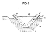
- the conical inside wall member 16 is used as a conical lower inside wall member 18 as shown in Fig. 5 and installed on the reinforcing bars 12 and the bottom concrete 13 as a formwork, and a lower concrete 19 is placed from a concrete pouring pipe 191.
- the conical lower inside wall member 18 is prevented from floating by being filled water 20 or sewage treated water which serves as a weight.
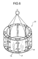
- GFRU panels 14 are fabricated to a ring-shape using bolts 15, nails or an adhesive to thereby form cylindrical inside wall members 21. Joints 17 are sealed with a resin, tape or adhesive as shown in Fig. 4 described above.
- the cylindrical inside wall members 21 are piled up and fabricated and used as an inside formwork.
- Sidewall reinforcing bars 23 are disposed using outside scaffolds 22, usual outside formworks 24 are disposed and a sidewall concrete 25 is placed.
- an upper inside wall member 27 is hung down and installed on a cylindrical sidewall portion 26 to which the sidewall concrete 25 has been placed.
- a member similar to the conical inside wall member 16 shown in Fig. 3 can be used as the upper inside wall member 27.
- the GFRU panels 14 are divided into several sections and hung down and then fabricated.
- the upper inside wall member 27 is used as an inside concrete placing formwork, upper reinforcing bars 28 are disposed as shown in Fig. 9, an upper concrete 30 is placed by installing an outside formworks 29, and then the outside formworks 29 and the outside scaffolds 22 are dismounted to thereby construct the digester tank 1 shown in Fig. 1.
- a concrete work, insulating work and corrosion preventing work can be executed together at a time in the construction of a biological reaction tank such as a thickner tank, anaerobic sewage treatment tank, denitrification tank in addition to the digester tank, a period of construction work can be greatly shortened and further a construction cost can be reduced by the omission of weather linings and inside scaffolds.
Abstract
Description
- The present invention relates to a sludge treatment tank and a construction method thereof, and more specifically, to a sludge treatment tank suitable for a biological reaction tank such as a digester tank and the like for the treatment of sludge in a sewage treatment plant and a construction method thereof.
- In general, sludge contained in inflow sewage is separated from water by a sedimentation treatment or the like, organic substances contained in the separated sludge are removed as a gas by a biological reaction effected in a digester tank having an optimum temperature and the remaining sludge is disposed of by being dehydrated, dried and burnt. The organic gas taken out is used as an energy source by being burnt.
- At present, there are constructed three types of tanks having considerably different longitudinal cross sectional shapes as the digester tank (refer to Concrete Digester Tank - I in "Environment Technology" published by Environmental Technology Research Institute, March 1982, pages 71-75, translated by Keitaro Aoyagi).
- Fig. 10 - Fig. 12 show these three types of the digester tanks, wherein Fig. 10 shows a tank having an egg-shaped, i.e. ovoid, longitudinal cross sectional shape, Fig. 11 shows a tank having a hexagon-shaped longitudinal cross sectional shape and Fig. 12 shows a tank having a flat longitudinal cross sectional shape. The flat tank formed to a cylindrical shape with a large diameter shown in Fig. 12 has a defect that it requires a large exclusive area, is disadvantageous in heat accumulation and operates at an expensive running cost. The egg-shaped tank shown in Fig. 10 makes sludge to smoothly circulate and flow, has a small exclusive area and operates at a low running cost because the tank can be easily insulated. Although the hexagon-shaped tank shown in Fig. 11 is somewhat inferior to the egg-shaped tank in performance, since it does not include such complex curves as used in the egg-shaped tank, it can be easily constructed. In Europe and the United States, a great many number of the egg-shaped tanks of Fig. 10 or the hexagon-shaped tanks of Fig. 11 are constructed.
- As shown in Fig. 10 - Fig. 12, these digester tanks are constructed such that a
corrosion preventing material 41 is coated on the inside wall of a reinforcedconcrete 40 and aheat insulator 42 and further aweather lining 43 is applied on the outside thereof. In this construction method, it is a usual practice that after reinforcing bars are fabricated, formworks are applied on the outside and the inside of the reinforcing bars and concrete is placed and a prestress is applied by high strength steel members. Further, the heat insulator is applied on the outside wall of the concrete for heat insulation and the weather lining is applied for finishing the outside of the concrete. Further, a corrosion preventing material is coated on the inside wall surface and thereafter machinery and equipment, pipings are installed in the tank. - However, the above conventional technology has the following problems:
- (1) scaffolds are necessary on the inside and the outside;
- (2) a heat insulator must be applied on the outside wall surface for heat insulation and further exterior finishing must be executed to provide durability to rain and water;
- (3) a corrosion preventing work must be executed to a concrete inside wall surface using thinner and the like in a closed working environment to use the tank as a sludge tank;
- (4) a troublesome and time-consuming job is needed to fabricate and remove formworks in a concrete work; and
- (5) a heat insulation work, exterior work and corrosion preventing work cannot be executed before a concrete structure is finished.
- An aim of the present invention for solving the above problems is to provide a sludge treatment tank capable of realizing labor saving in working processes in a field of construction work, reduction of a period of construction work and working in a good environment as well as a method of constructing the sludge treatment tank in the construction of a biological reaction tank such as a digester tank and the like. The sludge treatment tank of the present invention comprises a concrete tank including a member composed of a glass long-fiber reinforced foamed plastic composite material as an inside wall material also serving as a formwork.
- Further, the above aim can be achieved by a method of constructing a sludge treatment tank, comprising the step of using a member composed of a glass long-fiber reinforced foamed plastic composite material as the inside formworks of inside and outside formworks used to place concrete to the concrete sludge treatment tank.
- According to the above arrangement, since the glass long-fiber reinforced foamed plastic composite material has strength similar to or greater than that of wood, it can be used as a formwork, thus the composite material can be used as an inside wall member also serving as the formwork. Moreover, since the composite material contains closed cells and has heat insulating property, it is effective as an insulating material. Further, since the composite material is composed of a plastic material, it has a corrosion preventing action because it does not have a water absorbing property and is resistant to acid and alkali.
- Consequently, when the composite material is used as an inside wall member also serving as a formwork, a heat insulator and a corrosion preventing material, inside scaffolds are not needed and an insulating work, weather lining work and inside wall surface corrosion preventing work can be omitted. Further, the interior of the tank can be kept to a good working environment by the omission of the corrosion preventing work.
- Further, since the above glass long-fiber reinforced foamed plastic composite material is light in weight and can be easily handled, labor can be saved and a working efficiency can be improved in a field work.
- A preferred embodiment of the present invention will now be described hereinbelow by way of example only with reference to the accompanying drawings in which:
- Fig. 1 is a longitudinal cross sectional view showing a digester tank of an embodiment of the present invention;
- Fig. 2 is a longitudinal cross sectional view showing a part of a lower conical portion constructed by a method of the present invention;
- Fig. 3 is a conceptual view of conical inside wall members fabricated by the method of the present invention;
- Fig. 4 is a detailed view of a portion where panels are jointed by the method of the present invention;
- Fig. 5 is a longitudinal cross sectional view showing a part of the lower conical portion constructed by the method of the present invention;
- Fig. 6 is a perspective view showing a part of a sidewall cylindrical portion constructed by the method of the present invention;
- Fig. 7 is a longitudinal cross sectional view showing a part of the sidewall cylindrical portion constructed by the method of the present invention;
- Fig. 8 is a longitudinal cross sectional view showing a part of an upper conical portion constructed by the method of the present invention;
- Fig. 9 is a longitudinal cross sectional view showing a part of the upper conical portion constructed by the method of the present invention;
- Fig. 10 is a longitudinal cross sectional view showing an example of a conventional egg-shaped digester tank;
- Fig. 11 is a longitudinal cross sectional view showing an example of a conventional hexagon-shaped digester tank; and
- Fig. 12 is a longitudinal cross sectional view showing an example of a conventional flat digester tank.
- An embodiment of the present invention will be described with reference to the drawings. A
digester tank 1 of an embodiment according to the present invention includes a hexagon-shaped longitudinal cross section composed of a lowerconical portion 3, acylindrical sidewall portion 4 and an upperconical portion 5 supported bystakes 2. Atank wall 6 is composed of a reinforced concrete and applied with a prestress by highstrength steel members 7. - An outside wall is finished by placed concrete and an
inside wall member 8 of the tank is formed of a glass long-fiber reinforced formed urethane (hereinafter, abbreviated as GFRU) composite material. - That is, an example of the GFRU composite material is a formed urethane resin material with a specific gravity in a range of 0.30 - 0.80 composed of 65 - 45 wt% of an urethane resin and 35 - 55 wt% of glass long-fibers preferably, woven glass roving) in a composition ratio. It is more preferable from a view point of balance between strength and economic efficiency that the foamed urethane resin material is composed of 60 - 55 wt% of an urethane resin and 40 - 45 wt% of glass long-fibers and has a specific gravity of a range of 0.40 - 0.60.
- Note, saturated or unsaturated ester resin and thermoplastic foamed resin such as epoxy resin may be used as the foamed plastic material in addition to the urethane resin, and carbon fibers or organic fibers such as aramid fibers may be used as the reinforcing material in addition to the glass long-fibers. The aforesaid composite material is light in weight and excellent in dimensional stability, resistance to water absorption, durability, nail-holding power, wear resistance and impact resistance.
- Since the above GFRU member can be used as a member also serving as a formwork member, a heat insulator and a corrosion resistant member, the GFRU member is used as the
inside wall member 8 which also serves as a formwork when concrete is placed. - There is commercially available "Eslon Neo Lumber FFU" (trade name of Sekisui Chemical Co., Ltd.) as a GFRU product. Further, when a foamed urethane resin with a specific gravity of 0.35 which is composed of 60 wt% of an urethane resin and 40 wt% of glass long-fibers and has at least one surface covered with a water-proof layer (thickness: about 0.5 mm) composed of an unfoamed urethane resin containing a glass fiber mat and the like is used, a cost is further reduced and resistance to water absorption and wear resistance can be more improved.
- When the tank constructed as described above is filled with
sewage sludge 9 and is kept to a temperature of about 35°C, organic substances in the sludge are dissolved by anaerobes in the tank and amethane gas 10 is generated. The thus generated methane gas can be used as an energy source by being burnt. The sludge from which the organic substances are removed is disposed of by being dehydrated and dried. - Next, a method of constructing the digester tank shown in Fig. 1 will be described.
- As shown in Fig. 2, the
ground 11 is excavated, reinforcingbars 12 are disposed and abottom concrete 13 is placed. - As shown in Fig. 3,
GFRU panels 14 made in a factory are fabricated to a conical shape by ajig 161 usingbolts 15, nails or an adhesive to make a conicalinside wall member 16. In this case,joints 17 are sealed with a resin, tape or adhesive as shown in Fig. 4. - The conical
inside wall member 16 is used as a conical lower insidewall member 18 as shown in Fig. 5 and installed on thereinforcing bars 12 and thebottom concrete 13 as a formwork, and alower concrete 19 is placed from aconcrete pouring pipe 191. At the time, the conical lower insidewall member 18 is prevented from floating by being filledwater 20 or sewage treated water which serves as a weight. - As shown in Fig. 6,
GFRU panels 14 are fabricated to a ring-shape using bolts 15, nails or an adhesive to thereby form cylindricalinside wall members 21.Joints 17 are sealed with a resin, tape or adhesive as shown in Fig. 4 described above. - As shown in Fig. 7, the cylindrical inside
wall members 21 are piled up and fabricated and used as an inside formwork.Sidewall reinforcing bars 23 are disposed usingoutside scaffolds 22, usualoutside formworks 24 are disposed and asidewall concrete 25 is placed. - As shown in Fig. 8, an upper
inside wall member 27 is hung down and installed on acylindrical sidewall portion 26 to which thesidewall concrete 25 has been placed. A member similar to the conical insidewall member 16 shown in Fig. 3 can be used as the upper insidewall member 27. When the upperinside wall member 27 has a weight exceeding the capacity of a crane, theGFRU panels 14 are divided into several sections and hung down and then fabricated. - Finally, the upper inside
wall member 27 is used as an inside concrete placing formwork, upper reinforcingbars 28 are disposed as shown in Fig. 9, anupper concrete 30 is placed by installing anoutside formworks 29, and then theoutside formworks 29 and theoutside scaffolds 22 are dismounted to thereby construct thedigester tank 1 shown in Fig. 1. - According to the method as described above, the following advantages can be obtained:
- (1) since a concrete work, insulating work and corrosion preventing work can be executed together at a time, a period of construction work can be greatly shortened;
- (2) since a weather lining is not needed because the concrete is left in the placed state and further inside scaffolds can be omitted, a cost can be reduced;
- (3) a good working environment can be provided by avoiding a bad working environment caused when a corrosion preventing agent is coated using thinner or the like; and
- (4) since the production of GFRU panels and the fabrication thereof can be previously executed in a factory, labor can be saved in construction works executed in a field.
- As described above, according to the present invention, since a concrete work, insulating work and corrosion preventing work can be executed together at a time in the construction of a biological reaction tank such as a thickner tank, anaerobic sewage treatment tank, denitrification tank in addition to the digester tank, a period of construction work can be greatly shortened and further a construction cost can be reduced by the omission of weather linings and inside scaffolds.
Claims (11)
- A sludge treatment tank, comprising a concrete tank (1) including a member composed of a glass long-fiber reinforced foamed plastic composite material as an inside wall member (8) also serving as a formwork.
- A sludge treatment tank according to claim 1, wherein said concrete tank (1) has a cylindrical shape with the upper portion (5) thereof formed to a substantially conical shape and having an opening and the longitudinal cross sectional shape of said concrete tank is formed to any one of an egg-shape and a hexagon-shape.
- A sludge treatment tank according to claim l or 2, wherein said concrete tank (1) includes any one of reinforced concrete and prestressed concrete as a structural member.
- A sludge treatment tank according to any one of claims 1 to 3, wherein said concrete tank (I) is a biological reaction tank such as, for example, a digester tank.
- A sludge treatment tank according to any one of claims l to 4, wherein said composite material is composed of 60 - 55 wt% of foamed plastic and 40 - 45 wt% of long-fibers and has a specific gravity of 0.40 - 0.60.
- A sludge treatment tank according to claim 5, wherein said foamed plastic is any one selected from an urethane resin, a saturated ester resin, an unsaturated ester resin and an epoxy resin and said long-fibers are any one selected from glass fibers, carbon fibers and aramid fibers.
- A method of constructing a sludge treatment tank, comprising the step of using a member composed of a glass long-fiber reinforced foamed plastic composite material as the inside formworks of inside and outside formworks used to place concrete to said concrete sludge treatment tank.
- A method of constructing a sludge treatment tank according to claim 7, wherein said inside formwork is used as an inside wall member (8) of said sludge treatment tank after said concrete has been placed.
- A method of constructing a sludge treatment tank according to claim 7 or 8, wherein said sludge treatment tank has any one of an egg-shaped longitudinal cross sectional shape and a hexagon-shaped longitudinal cross sectional shape, the upper portion (5) and the lower portion (3) thereof are formed to a substantially conical shape and the barrel (4) thereof is formed to a cylindrical shape.
- A method of constructing a sludge treatment tank according to any one of claims 7 to 9, wherein said inside formworks are previously made to a predetermined shape in a factory and fabricated in a field.
- A method of constructing a sludge treatment tank according to any one of claims 7 to 10, wherein after the lower inside formworks of said sludge treatment tank are fabricated in the field, the thus fabricated inside formwork is filled with any of water or sewage treated water to prevent said formworks from floating.
Applications Claiming Priority (3)
| Application Number | Priority Date | Filing Date | Title |
|---|---|---|---|
| JP49555/95 | 1995-03-09 | ||
| JP4955595 | 1995-03-09 | ||
| JP7049555A JP3062581B2 (en) | 1995-03-09 | 1995-03-09 | Construction method of sludge treatment tank |
Publications (2)
| Publication Number | Publication Date |
|---|---|
| EP0732308A1 true EP0732308A1 (en) | 1996-09-18 |
| EP0732308B1 EP0732308B1 (en) | 1999-09-22 |
Family
ID=12834455
Family Applications (1)
| Application Number | Title | Priority Date | Filing Date |
|---|---|---|---|
| EP96301573A Expired - Lifetime EP0732308B1 (en) | 1995-03-09 | 1996-03-07 | Sludge treatment tank and construction method thereof |
Country Status (5)
| Country | Link |
|---|---|
| US (2) | US5672506A (en) |
| EP (1) | EP0732308B1 (en) |
| JP (1) | JP3062581B2 (en) |
| AT (1) | ATE184864T1 (en) |
| DE (1) | DE69604316T2 (en) |
Cited By (6)
| Publication number | Priority date | Publication date | Assignee | Title |
|---|---|---|---|---|
| FR2788542A1 (en) * | 1999-01-19 | 2000-07-21 | Freyssinet Int Stup | LIQUID RESERVOIR HAVING A REINFORCEMENT AND SEALING COATING, AND METHOD FOR THE PRODUCTION THEREOF |
| CN100513714C (en) * | 2007-06-11 | 2009-07-15 | 山东省农业科学院土壤肥料研究所 | Method for thermally insulating extro-wall of anaerobic digester in large-medium marsh-gas engineering |
| FR2994175A1 (en) * | 2012-07-31 | 2014-02-07 | Odipure | Mixed anaerobic digester, useful for decomposing organic material in e.g. industrial effluents, comprises tank having sidewall, reservoir storing gas produced by digestion surmounting tank and floor separating container of reservoir |
| WO2015051847A1 (en) * | 2013-10-10 | 2015-04-16 | Entexol Limited | A secondary containment system and method |
| CN104787998A (en) * | 2015-03-24 | 2015-07-22 | 泉州博超实业有限公司 | Production process of glass fiber reinforced plastic septic tank and production equipment for glass fiber reinforced plastic septic tank |
| WO2016209694A1 (en) * | 2015-06-24 | 2016-12-29 | Pallette Stone Corporation | Underground septic tank |
Families Citing this family (22)
| Publication number | Priority date | Publication date | Assignee | Title |
|---|---|---|---|---|
| JPH101383A (en) * | 1996-06-10 | 1998-01-06 | Toyo Dynam Kk | Fermentation tank |
| US5989407A (en) | 1997-03-31 | 1999-11-23 | Lynntech, Inc. | Generation and delivery device for ozone gas and ozone dissolved in water |
| US6622452B2 (en) | 1999-02-09 | 2003-09-23 | Energy Efficient Wall Systems, L.L.C. | Insulated concrete wall construction method and apparatus |
| US7254925B2 (en) * | 1999-02-09 | 2007-08-14 | Efficient Building Systems, L.L.C. | Insulated wall assembly |
| US7179642B2 (en) * | 1999-10-25 | 2007-02-20 | Ghd, Inc. | Method and apparatus for solids processing |
| US6451589B1 (en) * | 1999-10-25 | 2002-09-17 | Ghd, Inc. | Method and apparatus for solids processing |
| JP2005247324A (en) * | 2004-03-01 | 2005-09-15 | Ohbayashi Corp | Low-temperature pc tank, and method for constructing and using the same |
| US8470177B2 (en) * | 2006-11-27 | 2013-06-25 | Dvo Licensing, Inc. | Method and apparatus for anaerobic digestion of organic liquid waste streams |
| CN101600660B (en) * | 2006-11-27 | 2012-07-04 | Dvo公司 | Anaerobic digester employing circular tank |
| DE102008018270B4 (en) * | 2008-04-10 | 2014-12-11 | Martin Bergmann | Plastic containers |
| US8261918B1 (en) | 2009-10-08 | 2012-09-11 | James Robert Powell | Poly-container for solid phase-liquid phase separation |
| US8835155B2 (en) | 2009-11-25 | 2014-09-16 | Dvo Licensing, Inc. | Biosolids digester and process for biosolids production |
| CN201981192U (en) * | 2011-04-14 | 2011-09-21 | 戴学华 | Reverse conical glass fiber reinforced plastic methane tank |
| JP5704566B2 (en) * | 2011-05-23 | 2015-04-22 | 暁新日本建設株式会社 | Rainwater storage device |
| US8329455B2 (en) * | 2011-07-08 | 2012-12-11 | Aikan North America, Inc. | Systems and methods for digestion of solid waste |
| CN103669951A (en) * | 2013-12-30 | 2014-03-26 | 云南泰元建设工程项目管理有限公司 | Mould for building spherical or cylindrical cellar and method for building cellar by adoption of mould |
| JP6564564B2 (en) * | 2014-10-29 | 2019-08-21 | 鹿島建設株式会社 | Precast member manufacturing method and precast member |
| US10501349B1 (en) * | 2016-05-31 | 2019-12-10 | Jarrett Concrete Products | One piece watertight concrete structure |
| CN106121235A (en) * | 2016-08-29 | 2016-11-16 | 刘安华 | The method of construction of a kind of little water cellar and application |
| KR101934921B1 (en) * | 2016-11-16 | 2019-01-03 | 주식회사 에코피아 | Fixing structure of sheet |
| FR3111911A1 (en) * | 2020-06-26 | 2021-12-31 | L'air Liquide Societe Anonyme Pour L'etude Et L'exploitation Des Procedes Georges Claude | Biomass digester comprising a wall lined with an electrically conductive material and comprising carbon |
| CN112663774B (en) * | 2021-01-18 | 2022-06-28 | 中铁八局集团有限公司 | Construction method of unbonded prestressed large-diameter reinforced concrete thin-wall circular water tank |
Citations (3)
| Publication number | Priority date | Publication date | Assignee | Title |
|---|---|---|---|---|
| DE2330770A1 (en) * | 1973-06-16 | 1975-01-09 | Buecher Ewald Ingbuero | Fuel (oil) tanks - consist of a plastics-cement mixt. |
| US5231811A (en) * | 1992-03-16 | 1993-08-03 | Chicago Bridge & Iron Technical Services Company | Storage structures with layered thermal finish covering |
| WO1995031622A1 (en) * | 1994-05-18 | 1995-11-23 | Mats Persson | Method and arrangement in connection with containers having more than one wall |
Family Cites Families (3)
| Publication number | Priority date | Publication date | Assignee | Title |
|---|---|---|---|---|
| US4252767A (en) * | 1975-06-17 | 1981-02-24 | Daniel Zimmer | Composite building module |
| US5105590A (en) * | 1983-12-09 | 1992-04-21 | Dykmans Max J | Apparatus for constructing circumferentially wrapped prestressed structures utilizing a membrane including seismic coupling |
| US5315872A (en) * | 1993-05-11 | 1994-05-31 | Edo Corporation, Fiber Science Division | Liquid level sensor for electrically conductive liquid |
-
1995
- 1995-03-09 JP JP7049555A patent/JP3062581B2/en not_active Expired - Fee Related
-
1996
- 1996-03-04 US US08/610,252 patent/US5672506A/en not_active Expired - Fee Related
- 1996-03-07 AT AT96301573T patent/ATE184864T1/en not_active IP Right Cessation
- 1996-03-07 EP EP96301573A patent/EP0732308B1/en not_active Expired - Lifetime
- 1996-03-07 DE DE69604316T patent/DE69604316T2/en not_active Expired - Fee Related
-
1997
- 1997-06-16 US US08/876,300 patent/US5759849A/en not_active Expired - Fee Related
Patent Citations (3)
| Publication number | Priority date | Publication date | Assignee | Title |
|---|---|---|---|---|
| DE2330770A1 (en) * | 1973-06-16 | 1975-01-09 | Buecher Ewald Ingbuero | Fuel (oil) tanks - consist of a plastics-cement mixt. |
| US5231811A (en) * | 1992-03-16 | 1993-08-03 | Chicago Bridge & Iron Technical Services Company | Storage structures with layered thermal finish covering |
| WO1995031622A1 (en) * | 1994-05-18 | 1995-11-23 | Mats Persson | Method and arrangement in connection with containers having more than one wall |
Cited By (10)
| Publication number | Priority date | Publication date | Assignee | Title |
|---|---|---|---|---|
| FR2788542A1 (en) * | 1999-01-19 | 2000-07-21 | Freyssinet Int Stup | LIQUID RESERVOIR HAVING A REINFORCEMENT AND SEALING COATING, AND METHOD FOR THE PRODUCTION THEREOF |
| EP1022412A1 (en) * | 1999-01-19 | 2000-07-26 | Freyssinet International Stup | Liquid tank with reinforcing coating and sealing liner and process of manufacturing |
| CN100513714C (en) * | 2007-06-11 | 2009-07-15 | 山东省农业科学院土壤肥料研究所 | Method for thermally insulating extro-wall of anaerobic digester in large-medium marsh-gas engineering |
| FR2994175A1 (en) * | 2012-07-31 | 2014-02-07 | Odipure | Mixed anaerobic digester, useful for decomposing organic material in e.g. industrial effluents, comprises tank having sidewall, reservoir storing gas produced by digestion surmounting tank and floor separating container of reservoir |
| WO2015051847A1 (en) * | 2013-10-10 | 2015-04-16 | Entexol Limited | A secondary containment system and method |
| CN104787998A (en) * | 2015-03-24 | 2015-07-22 | 泉州博超实业有限公司 | Production process of glass fiber reinforced plastic septic tank and production equipment for glass fiber reinforced plastic septic tank |
| CN104787998B (en) * | 2015-03-24 | 2016-08-17 | 泉州博超实业有限公司 | A kind of production technology of glass toughening manure pit |
| WO2016209694A1 (en) * | 2015-06-24 | 2016-12-29 | Pallette Stone Corporation | Underground septic tank |
| US10189731B2 (en) | 2015-06-24 | 2019-01-29 | Pallette Stone Corporation | Underground septic tank |
| US10954148B2 (en) | 2015-06-24 | 2021-03-23 | Pallette Stone Corporation | Underground storage tank |
Also Published As
| Publication number | Publication date |
|---|---|
| DE69604316D1 (en) | 1999-10-28 |
| DE69604316T2 (en) | 2000-05-11 |
| JP3062581B2 (en) | 2000-07-10 |
| US5759849A (en) | 1998-06-02 |
| JPH08246538A (en) | 1996-09-24 |
| ATE184864T1 (en) | 1999-10-15 |
| US5672506A (en) | 1997-09-30 |
| EP0732308B1 (en) | 1999-09-22 |
Similar Documents
| Publication | Publication Date | Title |
|---|---|---|
| EP0732308B1 (en) | Sludge treatment tank and construction method thereof | |
| US5599599A (en) | Fiber reinforced plastic ("FRP")-concrete composite structural members | |
| US20020020129A1 (en) | Deep-ribbed, load-bearing, prefabricated insulative panel and method for joining | |
| KR850006371A (en) | Lined Rock Vessel | |
| KR101163026B1 (en) | Hybrid Formwork Comprising Half Circle Type of Paperboard Tube and A Method of Forming Cylindrical Structure Using the Same | |
| US20040065033A1 (en) | Prefabricated construction element for buildings | |
| US7348047B2 (en) | Multi-layered structural corrosion resistant composite liner | |
| KR100472106B1 (en) | A concrete absolutely-type merger septic tank structure and an assembly set and the construction way to establish the above-mentioned merger septic tank structure | |
| Goncharenko et al. | Repair and refurbishment technologies for inspection shafts in deep-level sewer tunnels | |
| US4190993A (en) | Liner construction | |
| JP4309835B2 (en) | Concrete storage tank and its construction method | |
| CN1803699A (en) | Hybrid fiber reinforced resin composite material/concrete combination structure and method for manufacturing the same | |
| KR20210076325A (en) | Small prefabricated water tank. | |
| KR20130017809A (en) | Nano silver treatment and hybrid of rain reservoir and permeate system | |
| RU2788372C1 (en) | Reinforced concrete power transmission line pole with locally restored section | |
| KR200263619Y1 (en) | Underground support structure of under construction using a complex material synthetic panel | |
| KR102276492B1 (en) | Carbon Fiber Reinforcement Construction Method On The Upper And Lower Surfaces Of The Bridge | |
| KR200203612Y1 (en) | Prefabricated structure | |
| CN217326620U (en) | Reinforced structure of precast concrete board | |
| CN214144395U (en) | Steel pipe restraint type steel recycled concrete combined hollow column wrapped with FRP (fiber reinforced plastic) | |
| CN210218945U (en) | Fiber reinforced composite winding pipe | |
| KR102032930B1 (en) | FRP tank sewage treatment equipment | |
| Naaman | Ferrocement: international revival | |
| Real | Use of Polymer Materials in Construction | |
| SU1571167A1 (en) | Wall panel |
Legal Events
| Date | Code | Title | Description |
|---|---|---|---|
| PUAI | Public reference made under article 153(3) epc to a published international application that has entered the european phase |
Free format text: ORIGINAL CODE: 0009012 |
|
| AK | Designated contracting states |
Kind code of ref document: A1 Designated state(s): AT DE FR IT |
|
| 17P | Request for examination filed |
Effective date: 19961028 |
|
| GRAG | Despatch of communication of intention to grant |
Free format text: ORIGINAL CODE: EPIDOS AGRA |
|
| 17Q | First examination report despatched |
Effective date: 19981124 |
|
| GRAG | Despatch of communication of intention to grant |
Free format text: ORIGINAL CODE: EPIDOS AGRA |
|
| GRAH | Despatch of communication of intention to grant a patent |
Free format text: ORIGINAL CODE: EPIDOS IGRA |
|
| GRAH | Despatch of communication of intention to grant a patent |
Free format text: ORIGINAL CODE: EPIDOS IGRA |
|
| RAP1 | Party data changed (applicant data changed or rights of an application transferred) |
Owner name: SEKISUI KAGAKU KOGYO KABUSHIKI KAISHA Owner name: THE ZENITAKA CORPORATION |
|
| GRAA | (expected) grant |
Free format text: ORIGINAL CODE: 0009210 |
|
| AK | Designated contracting states |
Kind code of ref document: B1 Designated state(s): AT DE FR IT |
|
| REF | Corresponds to: |
Ref document number: 184864 Country of ref document: AT Date of ref document: 19991015 Kind code of ref document: T |
|
| REF | Corresponds to: |
Ref document number: 69604316 Country of ref document: DE Date of ref document: 19991028 |
|
| ITF | It: translation for a ep patent filed |
Owner name: FUMERO BREVETTI S.N.C. |
|
| ET | Fr: translation filed | ||
| PLBE | No opposition filed within time limit |
Free format text: ORIGINAL CODE: 0009261 |
|
| STAA | Information on the status of an ep patent application or granted ep patent |
Free format text: STATUS: NO OPPOSITION FILED WITHIN TIME LIMIT |
|
| 26N | No opposition filed | ||
| PGFP | Annual fee paid to national office [announced via postgrant information from national office to epo] |
Ref country code: DE Payment date: 20030324 Year of fee payment: 8 |
|
| PGFP | Annual fee paid to national office [announced via postgrant information from national office to epo] |
Ref country code: FR Payment date: 20030327 Year of fee payment: 8 Ref country code: AT Payment date: 20030327 Year of fee payment: 8 |
|
| PG25 | Lapsed in a contracting state [announced via postgrant information from national office to epo] |
Ref country code: AT Free format text: LAPSE BECAUSE OF NON-PAYMENT OF DUE FEES Effective date: 20040307 |
|
| PG25 | Lapsed in a contracting state [announced via postgrant information from national office to epo] |
Ref country code: DE Free format text: LAPSE BECAUSE OF NON-PAYMENT OF DUE FEES Effective date: 20041001 |
|
| PG25 | Lapsed in a contracting state [announced via postgrant information from national office to epo] |
Ref country code: FR Free format text: LAPSE BECAUSE OF NON-PAYMENT OF DUE FEES Effective date: 20041130 |
|
| REG | Reference to a national code |
Ref country code: FR Ref legal event code: ST |
|
| PG25 | Lapsed in a contracting state [announced via postgrant information from national office to epo] |
Ref country code: IT Free format text: LAPSE BECAUSE OF NON-PAYMENT OF DUE FEES Effective date: 20050307 |