EP0732181A1 - A porous molding tool formed by lamination molding and method of molding the molding tool - Google Patents
A porous molding tool formed by lamination molding and method of molding the molding tool Download PDFInfo
- Publication number
- EP0732181A1 EP0732181A1 EP96102359A EP96102359A EP0732181A1 EP 0732181 A1 EP0732181 A1 EP 0732181A1 EP 96102359 A EP96102359 A EP 96102359A EP 96102359 A EP96102359 A EP 96102359A EP 0732181 A1 EP0732181 A1 EP 0732181A1
- Authority
- EP
- European Patent Office
- Prior art keywords
- molding
- molding tool
- lamination
- tool
- suction holes
- Prior art date
- Legal status (The legal status is an assumption and is not a legal conclusion. Google has not performed a legal analysis and makes no representation as to the accuracy of the status listed.)
- Granted
Links
Images


Classifications
-
- B—PERFORMING OPERATIONS; TRANSPORTING
- B29—WORKING OF PLASTICS; WORKING OF SUBSTANCES IN A PLASTIC STATE IN GENERAL
- B29C—SHAPING OR JOINING OF PLASTICS; SHAPING OF MATERIAL IN A PLASTIC STATE, NOT OTHERWISE PROVIDED FOR; AFTER-TREATMENT OF THE SHAPED PRODUCTS, e.g. REPAIRING
- B29C33/00—Moulds or cores; Details thereof or accessories therefor
- B29C33/38—Moulds or cores; Details thereof or accessories therefor characterised by the material or the manufacturing process
- B29C33/3814—Porous moulds
-
- B—PERFORMING OPERATIONS; TRANSPORTING
- B29—WORKING OF PLASTICS; WORKING OF SUBSTANCES IN A PLASTIC STATE IN GENERAL
- B29C—SHAPING OR JOINING OF PLASTICS; SHAPING OF MATERIAL IN A PLASTIC STATE, NOT OTHERWISE PROVIDED FOR; AFTER-TREATMENT OF THE SHAPED PRODUCTS, e.g. REPAIRING
- B29C64/00—Additive manufacturing, i.e. manufacturing of three-dimensional [3D] objects by additive deposition, additive agglomeration or additive layering, e.g. by 3D printing, stereolithography or selective laser sintering
- B29C64/10—Processes of additive manufacturing
- B29C64/106—Processes of additive manufacturing using only liquids or viscous materials, e.g. depositing a continuous bead of viscous material
- B29C64/124—Processes of additive manufacturing using only liquids or viscous materials, e.g. depositing a continuous bead of viscous material using layers of liquid which are selectively solidified
- B29C64/129—Processes of additive manufacturing using only liquids or viscous materials, e.g. depositing a continuous bead of viscous material using layers of liquid which are selectively solidified characterised by the energy source therefor, e.g. by global irradiation combined with a mask
-
- B—PERFORMING OPERATIONS; TRANSPORTING
- B29—WORKING OF PLASTICS; WORKING OF SUBSTANCES IN A PLASTIC STATE IN GENERAL
- B29C—SHAPING OR JOINING OF PLASTICS; SHAPING OF MATERIAL IN A PLASTIC STATE, NOT OTHERWISE PROVIDED FOR; AFTER-TREATMENT OF THE SHAPED PRODUCTS, e.g. REPAIRING
- B29C33/00—Moulds or cores; Details thereof or accessories therefor
- B29C33/38—Moulds or cores; Details thereof or accessories therefor characterised by the material or the manufacturing process
- B29C33/3842—Manufacturing moulds, e.g. shaping the mould surface by machining
- B29C2033/385—Manufacturing moulds, e.g. shaping the mould surface by machining by laminating a plurality of layers
Definitions
- This invention relates to a molding tool and method for molding formed by lamination molding used for molding of a fibrous material, and this invention is to provide a new molding tool and method of molding which are devised to manufacture molding tools efficiently by utilizing lamination molding.
- pulp molding has been known as a molding method in which fibrous material is used, for example, this method has contributed to recycling and saving of resources and has been utilized to manufacture packaging which is not involved in environmental pollution because used paper is used fro manufacturing the packaging.
- pulp molding method pulp fibers agitated and suspended in water, subsequently to which thermosetting resin precondensate is added and suspended to attach to pulp fibers, then the suspension is premolded by vacuum suction through a molding tool of a desired shape, the premolded product is dried, then compression molded or heat-hardened to obtain finally a molded pulp product.
- a molding tool which is referred to as paper making type molding tool has been popularly used as a molding tool for pulp molding, in an example shown in Fig. 11, a molding tool "a” is formed in a block-like hexahedron shape with a projection by casting.
- the molding tool “a” has a recess "b” which opens upward, the opening "c” is covered with a cover d, thus the molding tool a is structured so that the internal of the recess "b” is brought to a reduced pressure by suction using a vacuum aspirator "e".
- the molding tool "a” is provided with many suction holes f, f, ... for connecting between the recess "b" and the internal.
- the molding tool “a” is provided with meshes g, g, ...for covering the surface of the molding tool "a", and in the case that the molding tool "a” is complex in its shape, the molding tool is divided to a plurality of split molding tools a1, a2, ....
- the opening size of the meshes g, g, ... (usually smaller than 1 mm) are prescribed to be sufficiently smaller than that of the suction holes f, f, ....
- Fig. 12 shows the outline of molding by pulp molding.
- a liquid tank h is filled with a solution "i" containing pulp fibers with an individual length of several mm, the molding tool which is covered with meshes g, g, .... is dipped in the solution "i", then, the internal of the recess "b" of the molding tool "a” is sacked to vacuum, consequently pulp fibers are moves to the surface of the molding tool "a” namely meshes g, g, ... After the premolding, the premolded product is subjected to a series of processes such as drying process, and a pulp molded product having a replica shape of the molding tool "a".
- Such a conventional molding tool "a” requires some works for covering the surface of the molding tool with meshes g, g, ..., it is difficult to improve the efficiency of the work and shorten the work time because of this troublesome works, this is a problem of the conventional molding tool.
- a molding tool formed by lamination molding in accordance with the present invention is a molding tool in which many suction holes are formed as material lacks of laminated layers using lamination molding for molding a three-dimensional shape product by subjecting material to be laminated to prescribed treatment, thus, the problem is solved by applying this molding tool.
- material lacks are formed on each laminate layer, and layers are laminated one above another, thus many suction holes are formed on a molding tool.
- many suction holes are formed easily by laminate-forming many suction holes on a molding tool as an alternative for suction holes and meshes formed on a conventional paper making type molding tool.
- Fig. 1 is a diagram for illustrating schematically an embodiment of a molding equipment used in the present invention.
- Fig. 2 is a diagram for illustrating schematically an example of a light scanner and moving mechanism shown in Fig. 1.
- Fig. 3 is diagram for illustrating schematically a method of plane irradiation.
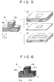
- Fig. 4 is a perspective view for illustrating an example of a basic shape of a molding tool and for illustrating preparation of structural data involving the molding tool in cooperation with Fig. 5 to Fig. 8.
- Fig. 5 is a perspective view for illustrating cross-sectional views at planes of a contour interval of the basic shape shown in Fig. 4.
- Fig. 6 is a perspective view for illustrating a molding tool on which many suction holes are formed.
- Figs. 7A and 7B are diagrams for illustrating the forming of holes on a plane perpendicular to Z-axis in a X-Y-Z coordinate system applied to the basic shape shown in Fig. 4, wherein Fig. 7A is a diagram for illustrating a lattice and Fig. 7B is a diagram for illustrating schematically the light scanning to form portion B in Fig. 7A.
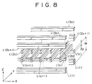
- Fig. 8 is a perspective view for illustrating the forming of holes on a plane perpendicular to X-axis or Y-axis in the X-Y-Z coordinate system applied to the basic shape shown in Fig. 4.
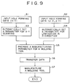
- Fig. 9 is a flow chart for describing the flow of forming a molding tool in accordance with the present invention.
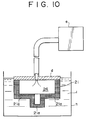
- Fig. 10 is a schematic diagram for illustrating pulp molding method using a molding tool in accordance with the present invention.
- Fig. 11 is a diagram for illustrating a molding method using a conventional paper making type molding tool and for illustrating a structure of a paper making type molding tool in cooperation with Fig. 12.
- Fig. 12 is a diagram for illustrating pulp molding method using a paper making type molding tool shown in Fig. 11.
- a molding tool formed by lamination molding and method of molding thereof in accordance with the present invention will be described referring to an embodiment shown in the figures.
- the present invention provides a molding tool having many suction holes by utilizing lamination molding, thereby, the present invention provides a method for molding a molded product of fibrous material by using the molding tool.
- the lamination molding herein refers to a method for forming a desired shape by applying prescribed treatments such as pressing and heat hardening to material to be laminated, and the lamination molding includes various molding methods such as powder melting molding, molten resin-spinning and laying molding, and sheet material lamination molding, that is, the lamination molding includes all methods which involve forming a three-dimensional product by laminating two-dimensional layers along a prescribed direction.
- Fig. 1 is a schematic diagram of an embodiment of a photo- molding equipment for using photo-setting resin method (resin the hardness of which is changed by photo-irradiation, for example, the resin includes ultraviolet-setting resin).
- shape data which is an output from a three-dimensional CAD (abbreviation of computer aided design) are supplied to a computer 2.
- the computer 2 serves as an operating table of the equipment 1, that is, serves as a directive center for setting various parameters and for processing data for manufacturing.
- the computer 2 is necessary also for conversion processing from shape data to cross-sectional shape data and for compiling of data.
- a shape is cut along a prescribed lamination axis based on the shape data to obtain cross-sectional shape data (for example, in the case that the vertical direction is selected as the lamination axis, the data are data of contour cross-sections, this data is referred to "contour cross-sectional data" hereinafter), and the data are subjected to data processing by program processing.
- various parameters including parameters involving diameter and pitch of many suction holes to be formed on a molding tool are required and the computer 2 generates automatically data involving the structure of the molding tool based on the manufacturing parameters.
- the computer 2 sends a control information corresponding to the contour cross-sectional data and manufacturing parameters to a controller 3.
- the controller 3 controls a light scanner 4 and moving mechanism 5 based on an input control information from the computer 2.
- the light scanner 4 is provided to irradiate the light on a desired position on the liquid surface 8a of photo-setting resin in a resin tank 7 by scanning the light from a light source 6.
- a laser source is employed as the light source 6 and the laser is scanned as shown in Fig. 2, laser 9, an acausto-optic modulator (abbreviated to "AOM” hereinafter) 10a, AOM driver 10b involving the driving control thereof, focus controller 11, scanners 12, and laser scanning controller 13 for controlling these scanners 12 are provided.
- the laser beam passes through the AOM 10a, focus controller 11, and scanner 12 and scans on the liquid surface 8a of photo-setting resin 8.
- the laser scanning controller 13 controls modulation of AOM 10a through the AOM driver 11 and controls the focus controller 11 and rotation of a galvano-mirror of a scanner 12 responding to a command from the controller 3.
- the moving mechanism 5 is provided for moving a stage 14 provided in the photo-setting resin tank 7 corresponding to lamination step of the photo-setting resin 8, for example, a mechanism using a ball screw is an example of an elevator mechanism for moving the stage 14 in vertical direction.
- the moving mechanism may be a mechanism that a feed screw 16a which is rotated by a stepping motor 15 extends in the vertical direction, to the feed screw a nut 16b is engaged spirally, and the stage 14 is moved in the vertical direction as the nut moves.
- a position information of the nut 16b is sent from a position detector 16c to the controller 3, the position of the stage 14 is controlled depending on a control signal sent from the controller 3 to the stepping motor 15.
- Any moving mechanism may be used as the moving mechanism 5 as long as the mechanism moves step-wise the stage 14 along the lamination direction to laminate resin layers along a prescribed direction which is hardened by light scanning on the stage 14.
- Fig. 2 the example of a structure in which the light source 6 and light scanner 4 are structured separately is shown because the laser 9 is used as the light source, however otherwise, for example as shown in Fig. 3, in an exposing system of planer irradiation, the light source 6 and light scanner 4 are incorporated in a one component by using a cathode ray tube (abbreviated to "CRT").
- CRT cathode ray tube
- the panel plane 17a of the CRT 17 is positioned above the liquid surface of photo-setting resin 8, an electron beam 17b emitted from CRT 17 is scanned using deflecting coils, and energy of the electron beam 17b is converted to optical energy on a fluorescent layer, the light is irradiated on the liquid surface 8a of photo-setting resin directly or through a optical element.
- a laminate molded product 18 is formed by repeating the hardening of photo-setting resin and moving of the stage 14 alternately.
- a molding tool formed as a lamination molded product 18 has a structure having a cavity in the inside for favoring uniform suction and having many suction holes for passing from the external to the cavity, however, in some cases the cavity is not necessary, and a suction opening of the vacuum aspirator may be put tightly on a plane of the molding tool to suck.
- this example involves the molding tool with a basic shape of block-like hexahedron having a projection.
- a basic shape 19 of block-like hexahedron having a projection is prepared for manufacturing a molding tool as design data.
- the direction of the projection of the block is assigned to Z-axis for accommodating the basic shape 19 to an orthogonal coordinate system, and for assigning X-axis and Y-axis perpendicular to Z-axis, the longitudinal direction of the base 19b of the block 19a of the basic shape 19 is assigned to X-axis.
- the basic shape 19 is sliced in planes perpendicular to Z-axis direction for slicing processing.
- the basic shape 19 is cut along many planes 20, 20, ... perpendicular to Z-axis and provided with a certain interval along Z-axis to prepare contour cross-sectional data for each plane.
- Fig. 6 shows a molding tool 21 obtained by forming many suction holes 21a, 21a, ...extending to X, Y, and Z-directions on the basic shape 19. These suction holes 21a, 21a, ... are necessary to deposit fibrous material.
- Figs. 7A and 7B and Fig. 8 are diagrams for illustrating the forming of suction holes 21a, 21a, ... at a portion A marked with a circle shown in Fig. 6, Figs. 7A and 7B illustrate the forming of holes on the plane parallel to an X-Y plane and Fig. 8 illustrates the forming of holes parallel to Z-X plane or Z-Y plane.
- Fig. 7A illustrates net-like lattice 22 constituted with straight lines extending to vertical direction and horizontal direction viewing from Z-direction, "N" represents hole diameter and "n” represents a width of a lattice.
- lattice skeletons 22a, 22a, ... with a width of "n” are portions hardened by light scanning of photo-setting resin 8, in this example, square holes with a side length of "N" are arranged along to X-direction and Y-direction, and a wall with a width of "n” partitions adjacent holes.
- Fig. 7B illustrates schematically the forming of the lattice at the portion "B" marked with an ellipse shown in Fig. 7A.
- Circles 23 represent a laser spot respectively, a diameter "D” represents the spot diameter.
- a lattice skeleton width "n” is determined based on the number of circles 23, 23, ... arranged side by side and the overlapping of these circles. For example, in the case that "L” represents the scanning interval of the laser spot and a distance between centers of adjacent circles is equal for all circles, the lattice skeleton width "n” is equal to a sum of "D” and an integral multiple of "n". Especially as shown in the figure, in the case that circles 23, 23, ...
- SK in the figure represents a skip width, in this range the scanning of laser along X-direction is required to interrupt for forming holes. Therefore, the skip width "SK" is equal to the hole diameter "N".
- the skip interval “SD” represents a skip interval, and equal to a sum of the lattice width "n” and the hole diameter "N".
- the skip interval “SD” is an interval from starting of light scanning on a range of a lattice width "n” to restarting of light scanning on the next range with interpolation of a skip width "SK".
- the skip interval may be prescribed to a value less than the pulp fiber length (for example 1 mm).
- values of various parameters can be determined based on the hole diameter "N”, lattice skeleton width "n”, and laser spot diameter "D", thus square holes extending to Z-direction are formed by laminating lattices 22.
- Fig. 8 shows the forming of holes in a plane perpendicular to X-axis or Y-axis
- [l(1) to l(c)] represents resin skeletons formed by light scanning in X-direction
- [l(c+1) to l(2c)] represents resin skeletons laminated one above another on l(c) by light scanning in Y-direction
- [l(2c+1) to l(3c)] represents resin skeletons laminated one above another on l(2c) by light scanning in X-direction.
- suffix number in parentheses is prescribed to increase along in the positive direction of Z-axis, therefore, a skeleton having larger suffix number is laid on the previous skeleton having smaller suffix number one above another.
- Thickness "Zp" of l(1) to l(3c) in Z-direction represents a lamination pitch
- hole diameter "M" in Z-direction is equal to a integral multiple of "Zp” for a constant value of the lamination pitch "Zp”.
- the hole diameter "M” between l(1) and l(c) is equal to the product of the lamination pitch "Zp” and the number of laminate from l(1) to l(c), namely "c”.
- This is true for other hole diameters such as a hole diameter from l(c) to l(2c) or from (2c+1) to (3c).
- Hole interval formed in Z-direction (namely interval between l(c) and l(2c+1)) is determined based on the number of laminates from l(c+1) to l(2c) extending in Y-direction.
- the hole diameter "M" in a plane parallel to Z-Y plane and Z-X plane is determined based on the lamination pitch "Zp" and the number of laminates "c", thereby, square holes extending to X-direction or Y-direction are formed.
- Fig. 9 is a flow chart for illustrating the flow of preparation of a molding tool including the above mentioned procedures (a3).
- step S1 data necessary for hole forming in a plane parallel to X-Y plane is supplied, and in the step S2, as described in Fig. 8, data necessary for hole forming in a plane parallel to Z-X plane and Z-Y plane is supplied.
- a parameter for light scanning in X-Y plane is set automatically from the input data in the step S1.
- the parameter serves as basic information for laser scanning by the light scanner 4.
- a parameter necessary for controlling in the laminating direction is set automatically from the input data in the step S2.
- the parameter serves as basic information for controlling of the stage 14 by the moving mechanism 5.
- the parameters obtained in the steps S3 and S4 are incorporated in the manufacturing parameter as a part thereof in the step S5.
- the manufacturing parameter includes all the information necessary for manufacturing of a molding tool 21, and the manufacturing parameter information can be stored in the computer 2 as a data base, that is, data can be accumulated.
- data base that is, data can be accumulated.
- not only existing data is selected by selecting desired data from various stored data but also the stored data is used as the basic data for compiling of stored data and for optimal designing of a molding tool utilizing CAE (abbreviation of computer aided engineering).
- Controlling information corresponding to the manufacturing parameters is data-transferred to the controller 3 in the step S6, and the light scanner 4 and moving mechanism 5 are controlled in compliance with a command from the controller 3.
- step S7 cross-sectional layer are formed corresponding to every down-moving step of the stage 14 driven by the moving mechanism 5, many thin cross-sectional layers are laminated, then a molding tool grows as the lamination proceeds.
- a method in which bristle-like resin layers are laminated by laser beam scanning in the case of planer irradiation method as shown in Fig. 3, a picture information corresponding to a lattice pattern as shown in Figs. 7A and 7B is supplied to the CRT 17, and the lattice pattern is displayed on the irradiation plane.
- the basic shape 19 of the molding tool is accommodated in an orthogonal coordinate system and holes are formed in directions along each axis, however otherwise, a basic shape of a molding tool may be accommodated in an oblique coordinate system to form holes directed in oblique directions or the center of holes may be moved along a prescribed curve to form holes in different directions optionally.
- the shape of holes is not limited to the above mentioned square shape and any shape (for example, circular hole, hexagonal hole, etc.) may be selected as long as it does not causes a problem in the manufacturing.
- the equipment is structured so that a manufacturing parameter is prepared in the equipment 1 and it is transferred to the controller 3, however, in the case that a manufacturing parameter can be prepared in an external computer, the process is omitted, and data of the manufacturing parameter can be used as it is.
- the processing by the computer 2 has been carried out previously using another calculating means, the data of manufacturing parameter is transferred to the photo-molding equipment 1 via offline or online and the data is used as a control information for the controller 3.
- a molding tool for manufacturing of a molding tool, not limited to a method in which photo-setting resin is used, other methods in which laminating material reactive to electro-magnetic waves such as electron beam and radiation may be used, and otherwise, above mentioned various laminating molding methods may be used, however, use of the photo-setting resin method is advantageous in that material cost is low and manufacturing time is short.
- the shape of cross-sectional layers is not limited to the shape of one member, therefore, the shape of cross-sectional layers is set for a plurality of molding tools, and a plurality of molding tools are manufactured in only one laminating process, thus the production efficiency is improved.
- Fig. 10 is a diagram for illustrating the molding tool forming using a molding tool for pulp molding formed by the lamination molding method.
- section holes 21a, 21a, ... are formed on a molding tool 21 by the lamination molding method, these suction holes serves as an alternative for both conventional meshes g, g, ... and suction holes f, f, ....
- the molding tool 21 with block-like shape is reversed and dipped in a solution "i" containing pulp fibers, an upward-opened opening of the molding tool 21 is closed with a cover "d", and the internal of the recess 24 is brought to a reduced pressure using a vacuum aspirator "e”, then, the pulp fiber solution "i" in the liquid tank “h” penetrates to suction holes 21a, 21a, ... of the molding tool 21 and pulp fibers are deposited on the surface of the molding tool 21, and the deposit grows on the surface of the molding tool 21.
- the preliminary molded product is shaped using a female molding tool which corresponds to the product, processed through prescribed process such as drying, and taken out from the molding tool 21, thus a molded pulp product having a shape which corresponds to the shape of the molding tool 21 is manufactured.
- a molding tool with a porous structure and having many suction holes 21a, 21a, ... is manufactured using the lamination molding method, thus conventional use of split molding tool and meshes is made needless.
- small holes which are equivalent to openings of a mesh and suction holes of a molding tool are formed on a molding tool simultaneously when the molding tool is formed, even in the case of a molding tool with a complex shape, use of a split molding tool is needless, thus troublesome and skill-demanding works for fixing meshes on the surface of a molding tool and for fitting meshes when a design of the molding tool is changed are eliminated, and the manufacturing time of molding tools is shortened and the cost is reduced. For example, the time for manufacturing a molding tool used for manufacturing a packaging of electric appliances is compared.
- the conventional method requires several weeks, on the other hand, the method accordance with the present invention requires ten and several hours, thus it is obvious that the manufacturing time is significantly shortened.
- the use of the lamination molding method for forming a molding tool enables quick and flexible response to design change of the molding tool and additional production.
- suction holes are formed on a molding tool by lamination molding method
- these suction holes serves as an alternative for suction holes formed on a conventional paper making type molding tool and meshes used in conventional method, thus, in the case that a molding tool should be formed in a complex shape, it is not necessary to use a split molding tool and meshes and to fix meshes on a molding tool unlike a conventional paper making type molding tool, skill-demanding works are not required for workers, therefore molding tools are manufactured efficiently in a short time.
Abstract
Description
- This invention relates to a molding tool and method for molding formed by lamination molding used for molding of a fibrous material, and this invention is to provide a new molding tool and method of molding which are devised to manufacture molding tools efficiently by utilizing lamination molding.
- For example, a method which is referred to as pulp molding has been known as a molding method in which fibrous material is used, for example, this method has contributed to recycling and saving of resources and has been utilized to manufacture packaging which is not involved in environmental pollution because used paper is used fro manufacturing the packaging.
- In the pulp molding method, pulp fibers agitated and suspended in water, subsequently to which thermosetting resin precondensate is added and suspended to attach to pulp fibers, then the suspension is premolded by vacuum suction through a molding tool of a desired shape, the premolded product is dried, then compression molded or heat-hardened to obtain finally a molded pulp product.
- A molding tool which is referred to as paper making type molding tool has been popularly used as a molding tool for pulp molding, in an example shown in Fig. 11, a molding tool "a" is formed in a block-like hexahedron shape with a projection by casting. The molding tool "a" has a recess "b" which opens upward, the opening "c" is covered with a cover d, thus the molding tool a is structured so that the internal of the recess "b" is brought to a reduced pressure by suction using a vacuum aspirator "e".
- The molding tool "a" is provided with many suction holes f, f, ... for connecting between the recess "b" and the internal.
- The molding tool "a" is provided with meshes g, g, ...for covering the surface of the molding tool "a", and in the case that the molding tool "a" is complex in its shape, the molding tool is divided to a plurality of split molding tools a1, a2, .... The opening size of the meshes g, g, ... (usually smaller than 1 mm) are prescribed to be sufficiently smaller than that of the suction holes f, f, ....
- Fig. 12 shows the outline of molding by pulp molding.
- A liquid tank h is filled with a solution "i" containing pulp fibers with an individual length of several mm, the molding tool which is covered with meshes g, g, .... is dipped in the solution "i", then, the internal of the recess "b" of the molding tool "a" is sacked to vacuum, consequently pulp fibers are moves to the surface of the molding tool "a" namely meshes g, g, ... After the premolding, the premolded product is subjected to a series of processes such as drying process, and a pulp molded product having a replica shape of the molding tool "a".
- Such a conventional molding tool "a" requires some works for covering the surface of the molding tool with meshes g, g, ..., it is difficult to improve the efficiency of the work and shorten the work time because of this troublesome works, this is a problem of the conventional molding tool.
- In the case that the shape of a molding tool is complex or has a deep drawing shape, it is difficult to cover the molding tool with meshes, that is, various works such as works to fit meshes on the surface of the molding tool, to cover many split tools with meshes individually, some times to stretch a mesh for covering some portions of the molding tool, and to trim excessive portions of meshes are required, and these works require excellent skill for workers.
- A molding tool formed by lamination molding in accordance with the present invention is a molding tool in which many suction holes are formed as material lacks of laminated layers using lamination molding for molding a three-dimensional shape product by subjecting material to be laminated to prescribed treatment, thus, the problem is solved by applying this molding tool.
- In a molding method of molding tool formed by lamination molding in accordance with the present invention for solving the problem, material lacks are formed on each laminate layer, and layers are laminated one above another, thus many suction holes are formed on a molding tool.
- According to the present invention, many suction holes are formed easily by laminate-forming many suction holes on a molding tool as an alternative for suction holes and meshes formed on a conventional paper making type molding tool.
- Fig. 1 is a diagram for illustrating schematically an embodiment of a molding equipment used in the present invention.
- Fig. 2 is a diagram for illustrating schematically an example of a light scanner and moving mechanism shown in Fig. 1.
- Fig. 3 is diagram for illustrating schematically a method of plane irradiation.
- Fig. 4 is a perspective view for illustrating an example of a basic shape of a molding tool and for illustrating preparation of structural data involving the molding tool in cooperation with Fig. 5 to Fig. 8.
- Fig. 5 is a perspective view for illustrating cross-sectional views at planes of a contour interval of the basic shape shown in Fig. 4.
- Fig. 6 is a perspective view for illustrating a molding tool on which many suction holes are formed.
- Figs. 7A and 7B are diagrams for illustrating the forming of holes on a plane perpendicular to Z-axis in a X-Y-Z coordinate system applied to the basic shape shown in Fig. 4, wherein Fig. 7A is a diagram for illustrating a lattice and Fig. 7B is a diagram for illustrating schematically the light scanning to form portion B in Fig. 7A.
- Fig. 8 is a perspective view for illustrating the forming of holes on a plane perpendicular to X-axis or Y-axis in the X-Y-Z coordinate system applied to the basic shape shown in Fig. 4.
- Fig. 9 is a flow chart for describing the flow of forming a molding tool in accordance with the present invention.
- Fig. 10 is a schematic diagram for illustrating pulp molding method using a molding tool in accordance with the present invention.
- Fig. 11 is a diagram for illustrating a molding method using a conventional paper making type molding tool and for illustrating a structure of a paper making type molding tool in cooperation with Fig. 12.
- Fig. 12 is a diagram for illustrating pulp molding method using a paper making type molding tool shown in Fig. 11.
- A molding tool formed by lamination molding and method of molding thereof in accordance with the present invention will be described referring to an embodiment shown in the figures.
- The present invention provides a molding tool having many suction holes by utilizing lamination molding, thereby, the present invention provides a method for molding a molded product of fibrous material by using the molding tool.
- The lamination molding herein refers to a method for forming a desired shape by applying prescribed treatments such as pressing and heat hardening to material to be laminated, and the lamination molding includes various molding methods such as powder melting molding, molten resin-spinning and laying molding, and sheet material lamination molding, that is, the lamination molding includes all methods which involve forming a three-dimensional product by laminating two-dimensional layers along a prescribed direction.
- Fig. 1 is a schematic diagram of an embodiment of a photo- molding equipment for using photo-setting resin method (resin the hardness of which is changed by photo-irradiation, for example, the resin includes ultraviolet-setting resin).
- Data of a shape model (called shape data hereinafter) which is an output from a three-dimensional CAD (abbreviation of computer aided design) are supplied to a
computer 2. - The
computer 2 serves as an operating table of theequipment 1, that is, serves as a directive center for setting various parameters and for processing data for manufacturing. - The
computer 2 is necessary also for conversion processing from shape data to cross-sectional shape data and for compiling of data. In detail, a shape is cut along a prescribed lamination axis based on the shape data to obtain cross-sectional shape data (for example, in the case that the vertical direction is selected as the lamination axis, the data are data of contour cross-sections, this data is referred to "contour cross-sectional data" hereinafter), and the data are subjected to data processing by program processing. - For manufacturing a molding tool to be manufactured, various parameters including parameters involving diameter and pitch of many suction holes to be formed on a molding tool (the parameter is referred to "manufacturing parameter" hereinafter) are required and the
computer 2 generates automatically data involving the structure of the molding tool based on the manufacturing parameters. - The
computer 2 sends a control information corresponding to the contour cross-sectional data and manufacturing parameters to acontroller 3. - The
controller 3 controls alight scanner 4 andmoving mechanism 5 based on an input control information from thecomputer 2. - The
light scanner 4 is provided to irradiate the light on a desired position on theliquid surface 8a of photo-setting resin in aresin tank 7 by scanning the light from alight source 6. - For example, in the case that a laser source is employed as the
light source 6 and the laser is scanned as shown in Fig. 2,laser 9, an acausto-optic modulator (abbreviated to "AOM" hereinafter) 10a,AOM driver 10b involving the driving control thereof, focus controller 11,scanners 12, andlaser scanning controller 13 for controlling thesescanners 12 are provided. In detail, the laser beam passes through the AOM 10a, focus controller 11, andscanner 12 and scans on theliquid surface 8a of photo-setting resin 8. When, thelaser scanning controller 13 controls modulation of AOM 10a through the AOM driver 11 and controls the focus controller 11 and rotation of a galvano-mirror of ascanner 12 responding to a command from thecontroller 3. - The
moving mechanism 5 is provided for moving astage 14 provided in the photo-setting resin tank 7 corresponding to lamination step of the photo-setting resin 8, for example, a mechanism using a ball screw is an example of an elevator mechanism for moving thestage 14 in vertical direction. As shown in the figure, the moving mechanism may be a mechanism that afeed screw 16a which is rotated by a steppingmotor 15 extends in the vertical direction, to the feed screw anut 16b is engaged spirally, and thestage 14 is moved in the vertical direction as the nut moves. A position information of thenut 16b is sent from aposition detector 16c to thecontroller 3, the position of thestage 14 is controlled depending on a control signal sent from thecontroller 3 to the steppingmotor 15. Any moving mechanism may be used as themoving mechanism 5 as long as the mechanism moves step-wise thestage 14 along the lamination direction to laminate resin layers along a prescribed direction which is hardened by light scanning on thestage 14. - In Fig. 2, the example of a structure in which the
light source 6 andlight scanner 4 are structured separately is shown because thelaser 9 is used as the light source, however otherwise, for example as shown in Fig. 3, in an exposing system of planer irradiation, thelight source 6 andlight scanner 4 are incorporated in a one component by using a cathode ray tube (abbreviated to "CRT"). In detail, the panel plane 17a of theCRT 17 is positioned above the liquid surface of photo-setting resin 8, anelectron beam 17b emitted fromCRT 17 is scanned using deflecting coils, and energy of theelectron beam 17b is converted to optical energy on a fluorescent layer, the light is irradiated on theliquid surface 8a of photo-setting resin directly or through a optical element. - Thus, a laminate molded
product 18 is formed by repeating the hardening of photo-setting resin and moving of thestage 14 alternately. - A molding tool formed as a lamination molded
product 18 has a structure having a cavity in the inside for favoring uniform suction and having many suction holes for passing from the external to the cavity, however, in some cases the cavity is not necessary, and a suction opening of the vacuum aspirator may be put tightly on a plane of the molding tool to suck. - Next, procedures for generating data involving the structure of the molding tool are described referring to Fig. 4 to Fig. 8. For easy understanding, this example involves the molding tool with a basic shape of block-like hexahedron having a projection.
- First, shown in Fig. 4, a
basic shape 19 of block-like hexahedron having a projection is prepared for manufacturing a molding tool as design data. The direction of the projection of the block is assigned to Z-axis for accommodating thebasic shape 19 to an orthogonal coordinate system, and for assigning X-axis and Y-axis perpendicular to Z-axis, the longitudinal direction of thebase 19b of theblock 19a of thebasic shape 19 is assigned to X-axis. - Next, as shown in Fig. 5, the
basic shape 19 is sliced in planes perpendicular to Z-axis direction for slicing processing. In detail, thebasic shape 19 is cut alongmany planes - Fig. 6 shows a
molding tool 21 obtained by formingmany suction holes basic shape 19. Thesesuction holes - Figs. 7A and 7B and Fig. 8 are diagrams for illustrating the forming of
suction holes - Fig. 7A illustrates net-
like lattice 22 constituted with straight lines extending to vertical direction and horizontal direction viewing from Z-direction, "N" represents hole diameter and "n" represents a width of a lattice. In detail,lattice skeletons resin 8, in this example, square holes with a side length of "N" are arranged along to X-direction and Y-direction, and a wall with a width of "n" partitions adjacent holes. - Fig. 7B illustrates schematically the forming of the lattice at the portion "B" marked with an ellipse shown in Fig. 7A.
-
Circles 23 represent a laser spot respectively, a diameter "D" represents the spot diameter. A lattice skeleton width "n" is determined based on the number ofcircles - "SK" in the figure represents a skip width, in this range the scanning of laser along X-direction is required to interrupt for forming holes. Therefore, the skip width "SK" is equal to the hole diameter "N".
- "SD" represents a skip interval, and equal to a sum of the lattice width "n" and the hole diameter "N". In other wards, the skip interval "SD" is an interval from starting of light scanning on a range of a lattice width "n" to restarting of light scanning on the next range with interpolation of a skip width "SK". For example, in the case that length of pulp fibers is 2 to 3 mm for pulp molding, the skip interval may be prescribed to a value less than the pulp fiber length (for example 1 mm).
- As described herein above, in the hole forming for the plane perpendicular to X-Y plane, values of various parameters can be determined based on the hole diameter "N", lattice skeleton width "n", and laser spot diameter "D", thus square holes extending to Z-direction are formed by laminating
lattices 22. - Fig. 8 shows the forming of holes in a plane perpendicular to X-axis or Y-axis, [l(1) to l(c)] represents resin skeletons formed by light scanning in X-direction, [l(c+1) to l(2c)] represents resin skeletons laminated one above another on l(c) by light scanning in Y-direction, and [l(2c+1) to l(3c)] represents resin skeletons laminated one above another on l(2c) by light scanning in X-direction. In the above description, suffix number in parentheses is prescribed to increase along in the positive direction of Z-axis, therefore, a skeleton having larger suffix number is laid on the previous skeleton having smaller suffix number one above another.
- Thickness "Zp" of l(1) to l(3c) in Z-direction represents a lamination pitch, hole diameter "M" in Z-direction is equal to a integral multiple of "Zp" for a constant value of the lamination pitch "Zp". For example, the hole diameter "M" between l(1) and l(c) is equal to the product of the lamination pitch "Zp" and the number of laminate from l(1) to l(c), namely "c". This is true for other hole diameters such as a hole diameter from l(c) to l(2c) or from (2c+1) to (3c). Hole interval formed in Z-direction (namely interval between l(c) and l(2c+1)) is determined based on the number of laminates from l(c+1) to l(2c) extending in Y-direction.
- As described herein above, the hole diameter "M" in a plane parallel to Z-Y plane and Z-X plane is determined based on the lamination pitch "Zp" and the number of laminates "c", thereby, square holes extending to X-direction or Y-direction are formed.
- Fig. 9 is a flow chart for illustrating the flow of preparation of a molding tool including the above mentioned procedures (a3).
- In the step S1, as described in Figs. 7A and 7B, data necessary for hole forming in a plane parallel to X-Y plane is supplied, and in the step S2, as described in Fig. 8, data necessary for hole forming in a plane parallel to Z-X plane and Z-Y plane is supplied.
- In the step S3 subsequent to the step S1, a parameter for light scanning in X-Y plane is set automatically from the input data in the step S1. The parameter serves as basic information for laser scanning by the
light scanner 4. - In the step S4 subsequent to the step S2, a parameter necessary for controlling in the laminating direction is set automatically from the input data in the step S2. The parameter serves as basic information for controlling of the
stage 14 by the movingmechanism 5. - The parameters obtained in the steps S3 and S4 are incorporated in the manufacturing parameter as a part thereof in the step S5. The manufacturing parameter includes all the information necessary for manufacturing of a
molding tool 21, and the manufacturing parameter information can be stored in thecomputer 2 as a data base, that is, data can be accumulated. In detail, not only existing data is selected by selecting desired data from various stored data but also the stored data is used as the basic data for compiling of stored data and for optimal designing of a molding tool utilizing CAE (abbreviation of computer aided engineering). - Controlling information corresponding to the manufacturing parameters is data-transferred to the
controller 3 in the step S6, and thelight scanner 4 and movingmechanism 5 are controlled in compliance with a command from thecontroller 3. - Then, in the step S7, cross-sectional layer are formed corresponding to every down-moving step of the
stage 14 driven by the movingmechanism 5, many thin cross-sectional layers are laminated, then a molding tool grows as the lamination proceeds. - After lifting up of the stage 11 from the photo-setting
resin tank 7, prescribed treatment (for example, ultraviolet setting) is applied to the molding tool and thus themolding tool 21 is completed. - As described herein above, according to the lamination molding,
many suction holes molding tool 21 are formed as material lacks, thus amolding tool 21 having a porous structure is manufactured. - In the above mentioned embodiment, a method in which bristle-like resin layers are laminated by laser beam scanning, however, in the case of planer irradiation method as shown in Fig. 3, a picture information corresponding to a lattice pattern as shown in Figs. 7A and 7B is supplied to the
CRT 17, and the lattice pattern is displayed on the irradiation plane. - In the above mentioned embodiment, the
basic shape 19 of the molding tool is accommodated in an orthogonal coordinate system and holes are formed in directions along each axis, however otherwise, a basic shape of a molding tool may be accommodated in an oblique coordinate system to form holes directed in oblique directions or the center of holes may be moved along a prescribed curve to form holes in different directions optionally. The shape of holes is not limited to the above mentioned square shape and any shape (for example, circular hole, hexagonal hole, etc.) may be selected as long as it does not causes a problem in the manufacturing. - In the above mentioned embodiment, the equipment is structured so that a manufacturing parameter is prepared in the
equipment 1 and it is transferred to thecontroller 3, however, in the case that a manufacturing parameter can be prepared in an external computer, the process is omitted, and data of the manufacturing parameter can be used as it is. In detail, in this case, the processing by thecomputer 2 has been carried out previously using another calculating means, the data of manufacturing parameter is transferred to the photo-molding equipment 1 via offline or online and the data is used as a control information for thecontroller 3. - For manufacturing of a molding tool, not limited to a method in which photo-setting resin is used, other methods in which laminating material reactive to electro-magnetic waves such as electron beam and radiation may be used, and otherwise, above mentioned various laminating molding methods may be used, however, use of the photo-setting resin method is advantageous in that material cost is low and manufacturing time is short.
- In the above mentioned embodiment, a process for manufacturing one molding tool is described, however, use of the lamination molding method is advantageous in that a plurality of molding tools or a plurality of molding tool types is manufactured simultaneously. In detail, the shape of cross-sectional layers is not limited to the shape of one member, therefore, the shape of cross-sectional layers is set for a plurality of molding tools, and a plurality of molding tools are manufactured in only one laminating process, thus the production efficiency is improved.
- Fig. 10 is a diagram for illustrating the molding tool forming using a molding tool for pulp molding formed by the lamination molding method.
- As obvious from the above mentioned description,
many section holes molding tool 21 by the lamination molding method, these suction holes serves as an alternative for both conventional meshes g, g, ... and suction holes f, f, .... - In detail, as shown in the figure, the
molding tool 21 with block-like shape is reversed and dipped in a solution "i" containing pulp fibers, an upward-opened opening of themolding tool 21 is closed with a cover "d", and the internal of therecess 24 is brought to a reduced pressure using a vacuum aspirator "e", then, the pulp fiber solution "i" in the liquid tank "h" penetrates to suctionholes molding tool 21 and pulp fibers are deposited on the surface of themolding tool 21, and the deposit grows on the surface of themolding tool 21. The preliminary molded product is shaped using a female molding tool which corresponds to the product, processed through prescribed process such as drying, and taken out from themolding tool 21, thus a molded pulp product having a shape which corresponds to the shape of themolding tool 21 is manufactured. - As described herein above, a molding tool with a porous structure and having
many suction holes - In detail, small holes which are equivalent to openings of a mesh and suction holes of a molding tool are formed on a molding tool simultaneously when the molding tool is formed, even in the case of a molding tool with a complex shape, use of a split molding tool is needless, thus troublesome and skill-demanding works for fixing meshes on the surface of a molding tool and for fitting meshes when a design of the molding tool is changed are eliminated, and the manufacturing time of molding tools is shortened and the cost is reduced. For example, the time for manufacturing a molding tool used for manufacturing a packaging of electric appliances is compared. The conventional method requires several weeks, on the other hand, the method accordance with the present invention requires ten and several hours, thus it is obvious that the manufacturing time is significantly shortened.
- In the case that a conventional paper making type molding tool is used, larger suction holes f, f, ... collects more fibers than
smaller suction holes molding tool 21 allows pulp fibers to grow uniformly on the surface of the molding tool because of the uniform distribution of manysmall suction holes suction holes - The use of the lamination molding method for forming a molding tool enables quick and flexible response to design change of the molding tool and additional production.
- As obvious from the above mentioned description, according to the invention specified by the
claim 1 andclaim 2, many suction holes are formed on a molding tool by lamination molding method, these suction holes serves as an alternative for suction holes formed on a conventional paper making type molding tool and meshes used in conventional method, thus, in the case that a molding tool should be formed in a complex shape, it is not necessary to use a split molding tool and meshes and to fix meshes on a molding tool unlike a conventional paper making type molding tool, skill-demanding works are not required for workers, therefore molding tools are manufactured efficiently in a short time.
Claims (4)
- A molding tool manufactured by the lamination molding method which is used for molding molded fibrous material products and is the molding tool manufactured by the lamination molding method for forming three dimensional products by subjecting a material to be laminated to prescribed treatment, wherein many suction holes formed on a molding tool are formed as material lacks of laminated layers.
- A molding method of a molding tool manufactured by the lamination molding method which is used for molding molded fibrous material products and is the molding method for molding a molding tool manufactured by the lamination molding method for forming three dimensional products by subjecting a material to be laminated to prescribed treatment, wherein material lacks are formed on each laminated layer and said layer is laminated one above another, thereby, many suction holes of the material lacks are formed on the molding tool.
- A molding tool manufactured by the lamination molding method as claimed in claim 1, wherein photo-setting resin material is used as the laminating material.
- A molding method of a molding tool manufactured by the lamination molding method as claimed in claim 2, wherein a photo-setting resin method which uses photo-setting resin as the laminating material is used as the lamination molding method.
Applications Claiming Priority (3)
| Application Number | Priority Date | Filing Date | Title |
|---|---|---|---|
| JP7053723A JP2870445B2 (en) | 1995-02-20 | 1995-02-20 | Mold formed by additive manufacturing and method of forming the same |
| JP53723/95 | 1995-02-20 | ||
| JP5372395 | 1995-02-20 |
Publications (2)
| Publication Number | Publication Date |
|---|---|
| EP0732181A1 true EP0732181A1 (en) | 1996-09-18 |
| EP0732181B1 EP0732181B1 (en) | 2001-05-16 |
Family
ID=12950760
Family Applications (1)
| Application Number | Title | Priority Date | Filing Date |
|---|---|---|---|
| EP96102359A Expired - Lifetime EP0732181B1 (en) | 1995-02-20 | 1996-02-16 | A porous molding tool formed by lamination molding and method of molding the molding tool |
Country Status (5)
| Country | Link |
|---|---|
| US (1) | US5766647A (en) |
| EP (1) | EP0732181B1 (en) |
| JP (1) | JP2870445B2 (en) |
| DE (1) | DE69612774T2 (en) |
| MY (1) | MY114418A (en) |
Cited By (9)
| Publication number | Priority date | Publication date | Assignee | Title |
|---|---|---|---|---|
| WO1997018933A1 (en) * | 1995-11-23 | 1997-05-29 | The University Of Nottingham | Method of making a three-dimensional object |
| EP0830928A2 (en) * | 1996-09-20 | 1998-03-25 | Dsm N.V. | Resin composition and mold made from such resin, for forming fibrous material |
| GB2331040A (en) * | 1997-11-05 | 1999-05-12 | Universal Pulp Packaging Ltd | Porous mould for forming fibre products |
| US5965079A (en) * | 1995-04-25 | 1999-10-12 | 3D Systems, Inc. | Method and apparatus for making a three-dimensional object by stereolithography |
| EP3971346A1 (en) * | 2020-09-22 | 2022-03-23 | Hewlett-Packard Development Company, L.P. | Transfer screens to be 3d fabricated with determined pore placements |
| EP3971347A1 (en) * | 2020-09-22 | 2022-03-23 | Hewlett-Packard Development Company, L.P. | Addition of features to screens for forming wet parts with details |
| WO2022072555A1 (en) * | 2020-09-29 | 2022-04-07 | Zume, Inc. | Porous molds for molded fiber part manufacturing and method for additive manufacturing of same |
| CN116113535A (en) * | 2020-07-14 | 2023-05-12 | 惠普发展公司, 有限责任合伙企业 | Removal of holes from a screen device to increase flow uniformity |
| FR3140294A1 (en) * | 2022-10-04 | 2024-04-05 | Avec | Molding tooling for producing a part based on cellulose pulp and method of manufacturing a part based on cellulose pulp using said tooling |
Families Citing this family (4)
| Publication number | Priority date | Publication date | Assignee | Title |
|---|---|---|---|---|
| JPH1113000A (en) * | 1997-06-13 | 1999-01-19 | Sony Corp | Forming block and its production |
| US6361726B1 (en) * | 1999-10-15 | 2002-03-26 | Soon-Jai Kim | Method and apparatus for making inner packaging container having anti-electrostatic characteristics, using paper making process |
| DE102004022386B4 (en) * | 2004-05-01 | 2006-05-04 | Laserinstitut Mittelsachsen E.V. | Molding apparatus for micro-components has molding chamber in which particles are sintered by laser, external acousto-optical modulator below laser controlling beam so that it operates in pulsed or continuous wave mode |
| JP5293993B2 (en) * | 2008-01-09 | 2013-09-18 | ソニー株式会社 | Stereolithography apparatus and stereolithography method |
Citations (4)
| Publication number | Priority date | Publication date | Assignee | Title |
|---|---|---|---|---|
| GB2035602A (en) * | 1978-12-14 | 1980-06-18 | Pollak J | Forming three dimensional objects from two-dimensional designs using photopolymerisable compositions |
| DE4102258A1 (en) * | 1991-01-23 | 1992-07-30 | Artos Med Produkte | Negative copy mfr. from component using laser-cured fluid - by converting profile data into control signals for swivelling laser which locally cures resin around components which descends through fluid |
| WO1993016865A1 (en) * | 1992-02-27 | 1993-09-02 | Marck Patent Gmbh | Process for producing moulded bodies with a predetermined pore structure |
| US5296335A (en) * | 1993-02-22 | 1994-03-22 | E-Systems, Inc. | Method for manufacturing fiber-reinforced parts utilizing stereolithography tooling |
Family Cites Families (13)
| Publication number | Priority date | Publication date | Assignee | Title |
|---|---|---|---|---|
| US3722467A (en) * | 1968-02-13 | 1973-03-27 | Int Playtex Corp | Deposition apparatus |
| JPS51116212A (en) * | 1975-04-01 | 1976-10-13 | Yoshikazu Nakajima | Apparatus for making molded article from water containing pulp |
| JPS6331710A (en) * | 1986-07-26 | 1988-02-10 | 東陶機器株式会社 | Manufacture of porous mold for pressure-molding pottery |
| US5156856A (en) * | 1986-12-04 | 1992-10-20 | Ngk Insulators, Ltd. | Mold for forming molded body |
| US4867662A (en) * | 1987-01-29 | 1989-09-19 | Inax Corporation | Slip casting mold |
| DE3942528A1 (en) * | 1989-12-22 | 1991-06-27 | Didier Werke Ag | METHOD FOR PRODUCING A FIBER LIGHT STONE AND FIBER LIGHT STONE |
| SU1724472A1 (en) * | 1990-01-22 | 1992-04-07 | Украинский Научно-Исследовательский Институт Фарфоро-Фаянсовой Промышленности | Porous mould for ceramic products |
| US5124102A (en) * | 1990-12-11 | 1992-06-23 | E. I. Du Pont De Nemours And Company | Fabric useful as a concrete form liner |
| JP2518574B2 (en) * | 1991-09-26 | 1996-07-24 | 日本碍子株式会社 | Pressure casting mold |
| JPH0733023B2 (en) * | 1991-11-29 | 1995-04-12 | 住友ゴム工業株式会社 | Master model for tire mold |
| JP2836800B2 (en) * | 1992-03-06 | 1998-12-14 | 日本碍子株式会社 | Papermaking mold, papermaking method and papermaking apparatus for fiber molded product, and paper made fiber molded product |
| JPH0673200U (en) * | 1993-03-22 | 1994-10-11 | 株式会社ノリタケカンパニーリミテド | Mold for pulp molding |
| JPH08197553A (en) * | 1995-01-27 | 1996-08-06 | Sintokogio Ltd | Pulp mold forming die |
-
1995
- 1995-02-20 JP JP7053723A patent/JP2870445B2/en not_active Expired - Fee Related
-
1996
- 1996-02-14 MY MYPI96000556A patent/MY114418A/en unknown
- 1996-02-16 EP EP96102359A patent/EP0732181B1/en not_active Expired - Lifetime
- 1996-02-16 US US08/603,029 patent/US5766647A/en not_active Expired - Fee Related
- 1996-02-16 DE DE69612774T patent/DE69612774T2/en not_active Expired - Fee Related
Patent Citations (4)
| Publication number | Priority date | Publication date | Assignee | Title |
|---|---|---|---|---|
| GB2035602A (en) * | 1978-12-14 | 1980-06-18 | Pollak J | Forming three dimensional objects from two-dimensional designs using photopolymerisable compositions |
| DE4102258A1 (en) * | 1991-01-23 | 1992-07-30 | Artos Med Produkte | Negative copy mfr. from component using laser-cured fluid - by converting profile data into control signals for swivelling laser which locally cures resin around components which descends through fluid |
| WO1993016865A1 (en) * | 1992-02-27 | 1993-09-02 | Marck Patent Gmbh | Process for producing moulded bodies with a predetermined pore structure |
| US5296335A (en) * | 1993-02-22 | 1994-03-22 | E-Systems, Inc. | Method for manufacturing fiber-reinforced parts utilizing stereolithography tooling |
Cited By (14)
| Publication number | Priority date | Publication date | Assignee | Title |
|---|---|---|---|---|
| US6264873B1 (en) | 1988-04-18 | 2001-07-24 | 3D Systems, Inc. | Method of making a three-dimensional object by stereolithography |
| US6261507B1 (en) | 1994-04-25 | 2001-07-17 | 3D Systems, Inc. | Method of and apparatus for making a three-dimensional object by stereolithography |
| US5965079A (en) * | 1995-04-25 | 1999-10-12 | 3D Systems, Inc. | Method and apparatus for making a three-dimensional object by stereolithography |
| WO1997018933A1 (en) * | 1995-11-23 | 1997-05-29 | The University Of Nottingham | Method of making a three-dimensional object |
| US6110602A (en) * | 1995-11-23 | 2000-08-29 | University Of Nottingham | Method of making a three-dimensional object |
| EP0830928A2 (en) * | 1996-09-20 | 1998-03-25 | Dsm N.V. | Resin composition and mold made from such resin, for forming fibrous material |
| EP0830928A3 (en) * | 1996-09-20 | 1999-02-03 | Dsm N.V. | Resin composition and mold made from such resin, for forming fibrous material |
| US6013714A (en) * | 1996-09-20 | 2000-01-11 | Dsm N.V. | Resin composition and fibrous material forming mold |
| GB2331040A (en) * | 1997-11-05 | 1999-05-12 | Universal Pulp Packaging Ltd | Porous mould for forming fibre products |
| CN116113535A (en) * | 2020-07-14 | 2023-05-12 | 惠普发展公司, 有限责任合伙企业 | Removal of holes from a screen device to increase flow uniformity |
| EP3971346A1 (en) * | 2020-09-22 | 2022-03-23 | Hewlett-Packard Development Company, L.P. | Transfer screens to be 3d fabricated with determined pore placements |
| EP3971347A1 (en) * | 2020-09-22 | 2022-03-23 | Hewlett-Packard Development Company, L.P. | Addition of features to screens for forming wet parts with details |
| WO2022072555A1 (en) * | 2020-09-29 | 2022-04-07 | Zume, Inc. | Porous molds for molded fiber part manufacturing and method for additive manufacturing of same |
| FR3140294A1 (en) * | 2022-10-04 | 2024-04-05 | Avec | Molding tooling for producing a part based on cellulose pulp and method of manufacturing a part based on cellulose pulp using said tooling |
Also Published As
| Publication number | Publication date |
|---|---|
| EP0732181B1 (en) | 2001-05-16 |
| DE69612774D1 (en) | 2001-06-21 |
| DE69612774T2 (en) | 2001-11-29 |
| JPH08226100A (en) | 1996-09-03 |
| US5766647A (en) | 1998-06-16 |
| MY114418A (en) | 2002-10-31 |
| JP2870445B2 (en) | 1999-03-17 |
Similar Documents
| Publication | Publication Date | Title |
|---|---|---|
| US5766647A (en) | Molding tool formed by laminating molding | |
| GB2378151A (en) | Fabricating a three-dimensional article from powder | |
| CN110997286B (en) | Method and apparatus for providing control data and additive manufacturing method and apparatus | |
| US5500069A (en) | Three dimensional object-forming method | |
| US5402364A (en) | Three dimensional measuring apparatus | |
| US20040107019A1 (en) | Automated rapid prototyping combining additive and subtractive processes | |
| CN110297459B (en) | Trimming die manufacturing method, computer-readable storage medium, and CNC trimming die manufacturing machine | |
| EP0722386A1 (en) | Three-dimensional rapid prototyping | |
| CN1268047C (en) | Method and apparatus for applying optical fiber array energy source to laser sintering rapid forming | |
| KR20040028593A (en) | Method of manufacturing a three dimensional object | |
| CN102837131A (en) | Production technique for machining light guide plate by laser | |
| CN101049652A (en) | Integral forming method for overlay film powder in complex shape of geometrical body of disabled laser selection | |
| CN108025362B (en) | Control device and method for controlling deflection of laser beam | |
| Shan et al. | Curved layer slicing based on isothermal surface | |
| CN114346409A (en) | Real-time processing path generation system for three-dimensional scanning and verification | |
| CN112373016B (en) | Three-dimensional laminated modeling method, three-dimensional laminated modeling device, electronic device, and storage medium | |
| JPH0524118A (en) | Manufacture of electrode for processing mold | |
| JPH08244118A (en) | Method and apparatus for forming optical shaped product | |
| CN1306898A (en) | Fast prototype method | |
| WO1999059030A2 (en) | Method for determining resin curing areas in an optical stereolithography process | |
| JPH08238678A (en) | Optically molding machine | |
| US11718031B2 (en) | Method for improving lifespan of LCD of MSLA 3D printer | |
| CN111729982B (en) | Punching machine cutting station manufacturing method, storage medium and CNC (computerized numerical control) machine tool | |
| JP2000006252A (en) | Manufacture of stereo-lithographed matter | |
| JPH09309153A (en) | Molding die and manufacture thereof |
Legal Events
| Date | Code | Title | Description |
|---|---|---|---|
| PUAI | Public reference made under article 153(3) epc to a published international application that has entered the european phase |
Free format text: ORIGINAL CODE: 0009012 |
|
| AK | Designated contracting states |
Kind code of ref document: A1 Designated state(s): DE GB |
|
| 17P | Request for examination filed |
Effective date: 19970218 |
|
| 17Q | First examination report despatched |
Effective date: 19980604 |
|
| GRAG | Despatch of communication of intention to grant |
Free format text: ORIGINAL CODE: EPIDOS AGRA |
|
| GRAG | Despatch of communication of intention to grant |
Free format text: ORIGINAL CODE: EPIDOS AGRA |
|
| GRAG | Despatch of communication of intention to grant |
Free format text: ORIGINAL CODE: EPIDOS AGRA |
|
| GRAH | Despatch of communication of intention to grant a patent |
Free format text: ORIGINAL CODE: EPIDOS IGRA |
|
| GRAH | Despatch of communication of intention to grant a patent |
Free format text: ORIGINAL CODE: EPIDOS IGRA |
|
| GRAA | (expected) grant |
Free format text: ORIGINAL CODE: 0009210 |
|
| AK | Designated contracting states |
Kind code of ref document: B1 Designated state(s): DE GB |
|
| REF | Corresponds to: |
Ref document number: 69612774 Country of ref document: DE Date of ref document: 20010621 |
|
| REG | Reference to a national code |
Ref country code: GB Ref legal event code: IF02 |
|
| PLBE | No opposition filed within time limit |
Free format text: ORIGINAL CODE: 0009261 |
|
| STAA | Information on the status of an ep patent application or granted ep patent |
Free format text: STATUS: NO OPPOSITION FILED WITHIN TIME LIMIT |
|
| 26N | No opposition filed | ||
| PGFP | Annual fee paid to national office [announced via postgrant information from national office to epo] |
Ref country code: DE Payment date: 20070208 Year of fee payment: 12 |
|
| PGFP | Annual fee paid to national office [announced via postgrant information from national office to epo] |
Ref country code: GB Payment date: 20070214 Year of fee payment: 12 |
|
| GBPC | Gb: european patent ceased through non-payment of renewal fee |
Effective date: 20080216 |
|
| PG25 | Lapsed in a contracting state [announced via postgrant information from national office to epo] |
Ref country code: DE Free format text: LAPSE BECAUSE OF NON-PAYMENT OF DUE FEES Effective date: 20080902 |
|
| PG25 | Lapsed in a contracting state [announced via postgrant information from national office to epo] |
Ref country code: GB Free format text: LAPSE BECAUSE OF NON-PAYMENT OF DUE FEES Effective date: 20080216 |