EP0730357A2 - Frequency and frame synchronisation for OFDM - Google Patents
Frequency and frame synchronisation for OFDM Download PDFInfo
- Publication number
- EP0730357A2 EP0730357A2 EP96850036A EP96850036A EP0730357A2 EP 0730357 A2 EP0730357 A2 EP 0730357A2 EP 96850036 A EP96850036 A EP 96850036A EP 96850036 A EP96850036 A EP 96850036A EP 0730357 A2 EP0730357 A2 EP 0730357A2
- Authority
- EP
- European Patent Office
- Prior art keywords
- signal
- synchronization
- ofdm
- symbol
- fft
- Prior art date
- Legal status (The legal status is an assumption and is not a legal conclusion. Google has not performed a legal analysis and makes no representation as to the accuracy of the status listed.)
- Granted
Links
- 238000000034 method Methods 0.000 claims abstract description 33
- 230000010363 phase shift Effects 0.000 claims description 11
- 230000000875 corresponding effect Effects 0.000 claims description 9
- 230000002596 correlated effect Effects 0.000 claims description 6
- 230000010354 integration Effects 0.000 claims description 2
- 230000021615 conjugation Effects 0.000 claims 1
- 238000001514 detection method Methods 0.000 abstract description 7
- 230000001131 transforming effect Effects 0.000 abstract description 2
- 230000003111 delayed effect Effects 0.000 description 5
- 230000005540 biological transmission Effects 0.000 description 4
- 238000005070 sampling Methods 0.000 description 4
- 238000010276 construction Methods 0.000 description 3
- 238000004891 communication Methods 0.000 description 2
- 230000008569 process Effects 0.000 description 2
- 108010076504 Protein Sorting Signals Proteins 0.000 description 1
- 241001248035 Trigonidiinae Species 0.000 description 1
- 125000004122 cyclic group Chemical group 0.000 description 1
- 230000001934 delay Effects 0.000 description 1
- 238000011161 development Methods 0.000 description 1
- 238000010586 diagram Methods 0.000 description 1
- 239000006185 dispersion Substances 0.000 description 1
- 238000001914 filtration Methods 0.000 description 1
- 230000007246 mechanism Effects 0.000 description 1
- 238000012986 modification Methods 0.000 description 1
- 230000004048 modification Effects 0.000 description 1
- 230000001172 regenerating effect Effects 0.000 description 1
- 230000003252 repetitive effect Effects 0.000 description 1
- 230000001360 synchronised effect Effects 0.000 description 1
- 238000012546 transfer Methods 0.000 description 1
- 230000007704 transition Effects 0.000 description 1
Images


Classifications
-
- H—ELECTRICITY
- H04—ELECTRIC COMMUNICATION TECHNIQUE
- H04L—TRANSMISSION OF DIGITAL INFORMATION, e.g. TELEGRAPHIC COMMUNICATION
- H04L27/00—Modulated-carrier systems
- H04L27/26—Systems using multi-frequency codes
- H04L27/2601—Multicarrier modulation systems
- H04L27/2647—Arrangements specific to the receiver only
- H04L27/2655—Synchronisation arrangements
- H04L27/2662—Symbol synchronisation
- H04L27/2665—Fine synchronisation, e.g. by positioning the FFT window
-
- H—ELECTRICITY
- H04—ELECTRIC COMMUNICATION TECHNIQUE
- H04L—TRANSMISSION OF DIGITAL INFORMATION, e.g. TELEGRAPHIC COMMUNICATION
- H04L27/00—Modulated-carrier systems
- H04L27/26—Systems using multi-frequency codes
- H04L27/2601—Multicarrier modulation systems
- H04L27/2647—Arrangements specific to the receiver only
- H04L27/2655—Synchronisation arrangements
- H04L27/2657—Carrier synchronisation
-
- H—ELECTRICITY
- H04—ELECTRIC COMMUNICATION TECHNIQUE
- H04L—TRANSMISSION OF DIGITAL INFORMATION, e.g. TELEGRAPHIC COMMUNICATION
- H04L27/00—Modulated-carrier systems
- H04L27/26—Systems using multi-frequency codes
- H04L27/2601—Multicarrier modulation systems
- H04L27/2647—Arrangements specific to the receiver only
- H04L27/2655—Synchronisation arrangements
- H04L27/2662—Symbol synchronisation
Definitions
- the present invention relates to a system where information is transmitted in orthogonal channels.
- the information is transmitted in a number of channels.
- OFDM Orthogonal Frequency Division Multiplexing
- OFDM is a transmission method suitable for time dispersive channels.
- OFDM is planned to be used as tranmission method at a large scale within digital sound broadcasting, for instance DAB, HD-TV, high-capacity services on coppar cable, DTM line coding which basically is the same thing as OFDM etc.
- OFDM is implemented among other things as OFDM with guard space, respective OFDM with pulse forming.
- OFDM with guard space a part of the signal interval is detailed for said guard space.
- guard space a part of the symbol is repeated.
- OFDM with pulse forming the symbols are being pulse formed, which means that the side lobes from each symbol, in the frequency plane, can be supressed which gives a more reliable detection when perfect synchronization can not be guaranteed. This means that one repeats the whole, or a part of the symbol and then multiplies with the pulse form.
- WO 93/20627 a method and a device is shown which is intended to be used in a digital transmission system.
- the invention makes use of repetitive synchronization patterns which can be arranged in transmitted data or placed in time slots of their own.
- the synchronization information is cross correlated with a known value at which the synchronization signal is created by summing up the result from the cross correlation.
- US 3 883 729 is described av device for frame correlation in a time multiplexed transmission system.
- the device consists of logical circuits for correlation of an incoming signal with a signal which has been delayed. By that the correlation can be performed on just any signals provided they are repeated.
- the patent document WO 93/11616 describes a digital transmission process which utilizes OFDM. According to ther described process the protection slots are utilized for the transfer of data.
- the synchronization methods shall further be independent of existing standards and will be produced in different connections for OFDM-system.
- the aim with the present invention is to solve the above mentioned problems.
- the present invention relates to a method for synchronization of OFDM-systems.
- An analog signal is digitized in an A/D-converter.
- the digitized signal is transmitted on a number of channels.
- the signal is read into a synchronization block.
- From the synchronization signal the synchronization block determines the position of a frame clock.
- From the synchronization block a frame clock signal is transmitted to an FFT-block and a frequency control signal to an oscillator.
- the synchronization of the system is performed before FFT is performed on the signal.
- the signal includes a symbol and a repeated part of the symbol in the space provided for the signal.
- the signal is cross correlated at which the repeated part of the signal is given a positive contribution.
- the cross correlation is calculated by multiplication and sliding mean.
- the repeated part of the signal is complex conjugated and multiplied with corresponding part in the signal at which a second signal is created.
- the second signal is shifted a number of samples corresponding to the repeated part of the signal.
- the result is subtracted from the second signal and a third signal is created which is integrated and a filtered cross correlation sequence is obtained.
- the absolute value of the third signal is determined.
- a saw-tooth signal is obtained which is used for generation of a frame clock by utilizing the peak values of the third signal.
- the frequency error in the system is determined by calculation of the phase of the cross correlation when the cross correlation has its maximum.
- the phase shift of the cross correlation is proportional to the length of the symbol.
- the invention further relates to a device for synchronization at OFDM-system.
- a synchronization device is arranged to receive a signal, which signal is digitized and divided into a number of channels. Correlation of the signal is performed by the synchronization device.
- a synchronization signal is transmitted and the synchronization is performed before the FFT-function.
- the synchronization device is arranged to transmit a frame clock signal to an FFT-processor.
- the synchronization device further transmits a frequency signal to an oscillator at which the frequency is adjusted.
- the signal includes a symbol, L.
- the symbol is repeated at least to a part in the signal.
- the repeated signal, R is preferably placed after the symbol within the signal.
- the repeated signal, R is complex conjugated whereafter a multiplication with the corresponding part in the symbol, L, is performed in a multiplying device.
- a device for sliding mean is arranged to produce synchronization signals from the signal, M, obtained from the multiplication device.
- the device for sliding mean includes a shift device which is arranged to shift the signal, M, a number of steps corresponding to the length of the repeated signal, R. The result is subtracted from the original signal, M.
- the obtained signal, C is integrated in an integrating device.
- the synchronization device is arranged to calculate the absolute value of the signal, C.
- a signal, T including a sequence of triangular signals is produced.
- the signal generates a frame clock signal to the FFT-processor.
- the frequency error is determined in the synchronization device by determining the phase shift of the cross correlation.
- the phase shift is proportional to the frequency error.
- the frequency error is preferably measured at correlation maxima.
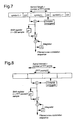
- Figure 1 shows the construction of the invention in the form of a block diagram.
- Figure 2 shows the construction of the signal at utilizing of guard space.
- Figure 3 shows the construction of the signal at utilizing of pulse forming.
- Figure 4 shows synchronization at utilization of guard space.
- Figure 5 shows synchronization at utilization of pulse forming.
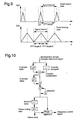
- Figure 6 shows sliding mean filter
- Figure 7 is a detailed picture for sliding mean in the case with guard interval.
- Figure 8 shows sliding mean in the case with pulse forming.
- Figure 9 shows a sliding cross correlation sequece.
- Figure 10 shows the implementation of the synchronization method.
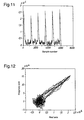
- Figure 11 shows the absolute values of cross correlation sequences over six signal intervals for the case OFDM with guard space.
- Figure 12 shows a filtered signal in the plane of complex numbers for the case OFDM with guard space.
- Figure 13 shows phase variation within a signal interval for the case OFDM with guard interval.
- Figure 14 shows the absolute value within a signal interval for the case OFDM with guard interval.
- Figure 15 shows the absolute value of a filtered signal for the case OFDM with pulse forming.
- Figure 16 shows a filtered signal in the plane of complex numbers for the case OFDM with pulse forming.
- Figure 17 shows the phase variations for seven signal intervals for the case OFDM with pulse forming.
- a digital signal is converted in an A/D-converter from analog signal to digital signal.
- the digital signal is divided into a number of, preferably narrow-band, channels.
- the digital signal is read into the synchronization block in the time domain, i.e. within fourier transforming of the signal via the FFT-processor according to Figure 1.
- FFT in this case means Fast Fourier Transform which is described in detail in other literature.
- the frame clock is regained for start of the input of data to the FFT-processor. For OFDM-reception it is of outmost importance that this input starts at the right point of time to make possible detection of data. The input point of time to the FFT-processor is therefore adjusted in relation to the regained frame clock.
- the frequency error can be estimated which is also performed in the synchronization block.
- the frequency error is utilized for a control loop for feedback to an NCO, Numerically Controlled Oscillator, which generates a complex rotating vector which is multiplied by the input signal for compensation of the frequency error.
- An alternative to this digital control is to control the local oscillators which are utilized for mixing down from radio frequency (the RF-parts are excluded in the Figure).
- the described synchronization method is focussed on the estimation of frame clock and frequency error. To use these parameters control mechanisms type Phase Lock Loop (PLL) are required, which is required in all types of synchronization methods.
- PLL Phase Lock Loop
- the method utilizes that a sufficient part of the information in the OFDM-signal is repeated during each signal interval. This condition is fulfilled in most cases where OFDM is utilized. In the following two main cases are described where this condition is fulfilled:
- guard space between the symbols are used, see Figure 2.
- Guard space has as its task to absorb the time dispersion between two following symbols, and to allow delays between a number of audible transmitters (simulcast network). If a 1024 points FFT is utilized, the symbols are sampled 1024 times. The number of samples for guard space can be between zero and a fourth of the FFT-length. Guard space is filled up in the time domain with repeated data, i.e. the first part of the symbol. Because the FFT-operation is cyclic, this causes that the starting point of time for sampling in of symbols can vary within guard space without any information being lost.
- Pulse forming means that the side lobes from each symbol, in the frequency plane, can be suppressed which gives a more reliable detection when perfect synchronization can not be guaranteed.
- the main characteristic of pulse forming for this synchronization method is that one utilizes data which is repeated during the signal interval in the transmitted signal.
- the synchronization method is based on time continous correlation of samples, time separated bythe repeating distance N.
- the cross correlation means that during the part of the signal interval which is repeated (correlated), data is given positive contibution.
- the cross correlation is calculated by multiplication and sliding mean.
- the symbol length consists of the number of FFT-points.
- half the symbol length is utilized for the symbol and half the symbol length for the repeated function. This means that the same information is repeated in its whole within the symbol length.
- the repeated symbol is complex conjugated and multiplied by the original signal. The mean value of the result is created and a synchronization signal is transmitted for control of the FFT-block.
- the principle for sliding mean is shown i Figure 6.
- the output signal from the sliding mean is written as C(k) is equal to sum from K equal to minus infinity to infinity.
- S ⁇ (k)s(k-N) - S ⁇ (k-n)s(k-N-n) S ⁇ complex conjugate
- s(k) is the sampled complex OFDM-signal
- N is the repeating distance
- n is the number of sample which is included in the sliding mean.
- N is equal to the number of FFT-points
- n is equal to the number of samples in guard space.
- pulse forming N is the number of FFT-points/two, and n is equal to N.
- the frequency error can easily be calculated from the cross correlation by calculating the phase where the cross correlation has its maximum, as is shown below.
- Received signal, s'(k) with frequency error can be expressed as s'(k) e j ⁇ k . s(k) where ⁇ is the frequency error.
- phase shift of the cross correlation is directly proportional to the frequency error ⁇ multiplied by the time distance N.
- N the repeating distance
- the greater the phase shift due to the frequency error which means that the maximal frequency error which can be detected is: N ⁇ ⁇ ⁇ rad.
- the frequency error must not exceed: f e ⁇ f s /(2N) where f e is the frequency error in Hz, and f s is the sampling frequency in Hz.
- the frequency error can, in prinicple, be measured any time within the repeating interval, but to obtain a more reliable estimation this should be done at cross correlation maxima since the phase in that point is based on the mean value of a large number of samples.
- a realization model for the synchronization is shown in Figure 8.
- the sampled complex OFDM-signal is it in two branches.
- the sample of the signal N (repeating distance) is delayed in a shift register.
- the shift register is most easily implemented with FIFO-memories or double gate RAM-memories.
- the other branch of the signal is complex conjugated. i.e. the imaginary part changes symbol.
- the two branches are after that multiplied making a complex multiplier.
- the output signal from the multiplier is again split into two branches one branch of which is delayed n samples (the number of sample in the sliding mean) in a shift register.
- the frame clock is regained from the absolute value of the filtered signal at which the function is performed before the PLL-block.
- the block "Phase Lock Loop” regains the frame clock, i.e. generates control signal to the FFT-process where it shall start the sampling in of the OFDM-symbol.
- the block “Phase Detector” has the task to calculate the phase of the correlation sequence at correlation maxima (synchronous with the frame clock).
- the block “Peak Detector” consequently trigs directly at the frame clock and calculates the phase at this point of time. The phase is at that time directly proportional to the frequency error.
- Phase detection shall only be performed once in each signal interval. It is however important that it is performed at the point of time for correlation maxima, since maximal precision of the phase is given at this point of time. Phase detection can be performed in different ways, for instance by a Pythagoreian processor, look-up table in EPROM, or by a signal processor.
- the phase (the frequency error) operates as input signal to a simple feed-back-loop for control of the frequency.
- FIG 15 At synchronization of pulse forms OFDM is in Figure 15 shown the absolute value of a filtered signal. In this case a 1024 points FFT with the modulation method QPSK has been utilized.
- Figure 11 shows the absolute value of the filtered signal over seven signal intervals. The signal also contains a positive frequency error which can not be seen in the absolute value. If the seven signal intervals in the complex number in Figure 16 is studied, the phase shift due to the frequency error the signal is influenced by will be evident. By a comparison with the guard space case it will be evident that the phase, in principle, is constant within the signal interval. However, maximal precision is given at correlation maxima.
Abstract
Description
- The present invention relates to a system where information is transmitted in orthogonal channels. The information is transmitted in a number of channels. OFDM, Orthogonal Frequency Division Multiplexing, is a transmission method suitable for time dispersive channels. At the present situation OFDM is planned to be used as tranmission method at a large scale within digital sound broadcasting, for instance DAB, HD-TV, high-capacity services on coppar cable, DTM line coding which basically is the same thing as OFDM etc.
- In the systems which at present are used for synchronization in OFDM-systems a number of multipliers are required. Each multiplier is comparatively expensive, so a minimization of the number of multipliers at the synchronization functions is desirable.
- OFDM is implemented among other things as OFDM with guard space, respective OFDM with pulse forming. In OFDM with with guard space a part of the signal interval is detailed for said guard space. In guard space a part of the symbol is repeated. At OFDM with pulse forming the symbols are being pulse formed, which means that the side lobes from each symbol, in the frequency plane, can be supressed which gives a more reliable detection when perfect synchronization can not be guaranteed. This means that one repeats the whole, or a part of the symbol and then multiplies with the pulse form.
- In the patent document WO 93/20627 a method and a device is shown which is intended to be used in a digital transmission system. The invention makes use of repetitive synchronization patterns which can be arranged in transmitted data or placed in time slots of their own. The synchronization information is cross correlated with a known value at which the synchronization signal is created by summing up the result from the cross correlation.
In the patent document US 3 883 729 is described av device for frame correlation in a time multiplexed transmission system. The device consists of logical circuits for correlation of an incoming signal with a signal which has been delayed. By that the correlation can be performed on just any signals provided they are repeated. - In the patent document US 5 363 415 is described a "carrying regenerating device" intended for mobile satellite communication. According to the document unique signal sequences are placed periodically among transmitted data. By the cross correlation with known stored sequences, phase- and frequency errors can be calculated.
- In document US 4 638 478 synchronization of frames in a TDM-system is described. The synchronization uses circuits which detect guard space. This information is used to secure correct frame synchronization.
- The patent document WO 93/11616 describes a digital transmission process which utilizes OFDM. According to ther described process the protection slots are utilized for the transfer of data.
- In the patent document US 4 598 413 a circuit arrangement for frame- and phase synchronization of a local sampling clock is described. The synchronization is performed by cross correlation of a received, unique synchronization sequence and one in the receiver stored known sequence.
- In the patent document EP 608024 synchronization of an OFDM-receiver is described. A received sequence is correlated with a sequence which is delayed one block length.
- In the patent document US 5 148 451 a device for carrier regain in a mobile satellite communications system is described. Unique synchronization words are placed periodically in the transmitted signal. A cross correlation circuit calculates the cross correlation between the received signal and a known stored sequence.
- Consequently it is previously known to perform cross correlation of an incoming signal with a locally stored signal. It is also known to utilize a delayed signal where signals exist at certain places in the protocol intended for synchronization. Further the documents show that it is previously known to partially utilize the guard spaces for synchronization.
- Simple methods to control time- and frequency errors at OFDM-transmission exist. In the known methods which are used at present there exists a data dependence. Further, known methods require that a number of multiplexings of the signal shall be performed. For each multiplexing a multiplier is required which is comparatively expensive. There is a desire to reduce the number of multipliers to reduce the costs for the synchronization function.
- In the known methods, further, special synchronization blocks or synchronization signals are used. The utilization of synchronization blocks or synchronization signals reduces the available space in the signal. In order to effectively utilize the available space it is therefore desirable to find methods where special synchronization blocks or synchronization signals have been excluded.
- The synchronization methods shall further be independent of existing standards and will be produced in different connections for OFDM-system.
- The aim with the present invention is to solve the above mentioned problems.
- The present invention relates to a method for synchronization of OFDM-systems. An analog signal is digitized in an A/D-converter. The digitized signal is transmitted on a number of channels. The signal is read into a synchronization block. From the synchronization signal the synchronization block determines the position of a frame clock. From the synchronization block a frame clock signal is transmitted to an FFT-block and a frequency control signal to an oscillator. The synchronization of the system is performed before FFT is performed on the signal.
- In a further development of the invention the signal includes a symbol and a repeated part of the symbol in the space provided for the signal. The signal is cross correlated at which the repeated part of the signal is given a positive contribution. The cross correlation is calculated by multiplication and sliding mean.
- The repeated part of the signal is complex conjugated and multiplied with corresponding part in the signal at which a second signal is created. The second signal is shifted a number of samples corresponding to the repeated part of the signal. The result is subtracted from the second signal and a third signal is created which is integrated and a filtered cross correlation sequence is obtained. The absolute value of the third signal is determined. A saw-tooth signal is obtained which is used for generation of a frame clock by utilizing the peak values of the third signal. The frequency error in the system is determined by calculation of the phase of the cross correlation when the cross correlation has its maximum. The phase shift of the cross correlation is proportional to the length of the symbol.
- The invention further relates to a device for synchronization at OFDM-system. A synchronization device is arranged to receive a signal, which signal is digitized and divided into a number of channels. Correlation of the signal is performed by the synchronization device. A synchronization signal is transmitted and the synchronization is performed before the FFT-function. The synchronization device is arranged to transmit a frame clock signal to an FFT-processor. The synchronization device further transmits a frequency signal to an oscillator at which the frequency is adjusted. The signal includes a symbol, L. The symbol is repeated at least to a part in the signal. The repeated signal, R, is preferably placed after the symbol within the signal. The repeated signal, R, is complex conjugated whereafter a multiplication with the corresponding part in the symbol, L, is performed in a multiplying device. A device for sliding mean is arranged to produce synchronization signals from the signal, M, obtained from the multiplication device. The device for sliding mean includes a shift device which is arranged to shift the signal, M, a number of steps corresponding to the length of the repeated signal, R. The result is subtracted from the original signal, M. The obtained signal, C, is integrated in an integrating device. The synchronization device is arranged to calculate the absolute value of the signal, C. A signal, T, including a sequence of triangular signals is produced. The signal generates a frame clock signal to the FFT-processor. The frequency error is determined in the synchronization device by determining the phase shift of the cross correlation. The phase shift is proportional to the frequency error. The frequency error is preferably measured at correlation maxima.
- Figure 1 shows the construction of the invention in the form of a block diagram.
- Figure 2 shows the construction of the signal at utilizing of guard space.
- Figure 3 shows the construction of the signal at utilizing of pulse forming.
- Figure 4 shows synchronization at utilization of guard space.
- Figure 5 shows synchronization at utilization of pulse forming.
- Figure 6 shows sliding mean filter.
- Figure 7 is a detailed picture for sliding mean in the case with guard interval.
- Figure 8 shows sliding mean in the case with pulse forming.
- Figure 9 shows a sliding cross correlation sequece.
- Figure 10 shows the implementation of the synchronization method.
- Figure 11 shows the absolute values of cross correlation sequences over six signal intervals for the case OFDM with guard space.
- Figure 12 shows a filtered signal in the plane of complex numbers for the case OFDM with guard space.
- Figure 13 shows phase variation within a signal interval for the case OFDM with guard interval.
- Figure 14 shows the absolute value within a signal interval for the case OFDM with guard interval.
- Figure 15 shows the absolute value of a filtered signal for the case OFDM with pulse forming.
- Figure 16 shows a filtered signal in the plane of complex numbers for the case OFDM with pulse forming.
- Figure 17 shows the phase variations for seven signal intervals for the case OFDM with pulse forming.
- In OFDM-systems a digital signal is converted in an A/D-converter from analog signal to digital signal. The digital signal is divided into a number of, preferably narrow-band, channels. The digital signal is read into the synchronization block in the time domain, i.e. within fourier transforming of the signal via the FFT-processor according to Figure 1. FFT in this case means Fast Fourier Transform which is described in detail in other literature. In the synchronization block the frame clock is regained for start of the input of data to the FFT-processor. For OFDM-reception it is of outmost importance that this input starts at the right point of time to make possible detection of data. The input point of time to the FFT-processor is therefore adjusted in relation to the regained frame clock.
- When the frame clock has been regained the frequency error can be estimated which is also performed in the synchronization block. The frequency error is utilized for a control loop for feedback to an NCO, Numerically Controlled Oscillator, which generates a complex rotating vector which is multiplied by the input signal for compensation of the frequency error. An alternative to this digital control is to control the local oscillators which are utilized for mixing down from radio frequency (the RF-parts are excluded in the Figure). The described synchronization method is focussed on the estimation of frame clock and frequency error. To use these parameters control mechanisms type Phase Lock Loop (PLL) are required, which is required in all types of synchronization methods. The method utilizes that a sufficient part of the information in the OFDM-signal is repeated during each signal interval. This condition is fulfilled in most cases where OFDM is utilized. In the following two main cases are described where this condition is fulfilled:
- OFDM-structure where so called guard space (guard interval) consisting of a repeated cyclical data is utilized.
- OFDM-structure with pulse forming.
- In most existing systems based on OFDM, guard space between the symbols are used, see Figure 2. Guard space has as its task to absorb the time dispersion between two following symbols, and to allow delays between a number of audible transmitters (simulcast network). If a 1024 points FFT is utilized, the symbols are sampled 1024 times. The number of samples for guard space can be between zero and a fourth of the FFT-length. Guard space is filled up in the time domain with repeated data, i.e. the first part of the symbol. Because the FFT-operation is cyclic, this causes that the starting point of time for sampling in of symbols can vary within guard space without any information being lost.
- There are further variants of OFDM which utilize pulse forming of the symbols. Pulse forming means that the side lobes from each symbol, in the frequency plane, can be suppressed which gives a more reliable detection when perfect synchronization can not be guaranteed.
- In the practise this means that one repeats the whole or a part of the symbol and then multiplies by the pulse form.
- In Figure 3 the signal interval at utilization of pulse forming is shown. Between two symbols the transition is made "soft" via pulse forming which gives suppressing of side lobes. Henceforth the symbols are however drawn as rectangles for the sake of simplicity.
- The main characteristic of pulse forming for this synchronization method is that one utilizes data which is repeated during the signal interval in the transmitted signal.
- The synchronization method is based on time continous correlation of samples, time separated bythe repeating distance N. The cross correlation means that during the part of the signal interval which is repeated (correlated), data is given positive contibution. The cross correlation is calculated by multiplication and sliding mean.
- In Figure 4 this is illustrated by the length of a symbol being equal to the number of FFT-points. In Figure 4 has been symbolized that a part of the beginning of the symbol L has been repeated in guard space, GS. The repeated signal in guard space, GS, is complex conjugated and multiplied by corresponding part in the original symbol L. The mean value of the result is created and produces a synchronization signal.
- In Figure 5 is shown the system at pulse forming. In this case the symbol length consists of the number of FFT-points. In this case half the symbol length is utilized for the symbol and half the symbol length for the repeated function. This means that the same information is repeated in its whole within the symbol length. The repeated symbol is complex conjugated and multiplied by the original signal. The mean value of the result is created and a synchronization signal is transmitted for control of the FFT-block.
- The principle for sliding mean is shown i Figure 6. The output signal from the sliding mean is written as C(k) is equal to sum from K equal to minus infinity to infinity.


- Synchronization models completed with method for sliding mean are shown in Figure 7 and 8 for the two cases.
- The product obtained at the multiplication of the complex conjugated signal and the original signal according to Figure 4 and 5 are read into the shift register in Figure 6. In the shift register the signal is shifted n times. The obtained signal is subtracted from the unshifted signal. The signal which has been obtained in this way is added to a signal which is shifted one step. In this way an integration of the signal is achieved. The result which after that is obtained is a filtered sliding mean cross correlation sequence equal to C(k). In the Figures 7 and 8 the whole process is shown by compilation of the Figures 4 and 6, respective 5 and 6,
- In Figure 9 the absolute value of the output signal, C(k), for both variants are shown.
- It is important to take the absolute value of C(k), since a frequency error can result in that the signal can be phase shifted which makes C(k) not real.
- Filtering of an absolute value calculation gives a saw-tooth shaped signal according to Figure 9 which is very suitable to feed a Phase Lock Loop (PLL) for generation of a frame clock to the following FFT-processor.
- The frequency error can easily be calculated from the cross correlation by calculating the phase where the cross correlation has its maximum, as is shown below. Received signal, s'(k) with frequency error can be expressed as


- The frequency error can, in prinicple, be measured any time within the repeating interval, but to obtain a more reliable estimation this should be done at cross correlation maxima since the phase in that point is based on the mean value of a large number of samples.
- A realization model for the synchronization is shown in Figure 8. The sampled complex OFDM-signal is it in two branches. In one branch the sample of the signal N (repeating distance) is delayed in a shift register. The shift register is most easily implemented with FIFO-memories or double gate RAM-memories. The other branch of the signal is complex conjugated. i.e. the imaginary part changes symbol. The two branches are after that multiplied making a complex multiplier.
- The output signal from the multiplier is again split into two branches one branch of which is delayed n samples (the number of sample in the sliding mean) in a shift register. The frame clock is regained from the absolute value of the filtered signal at which the function is performed before the PLL-block. There are different ways of simplifying the calculation of the absolute value to avoid further multiplications. A sufficiently good approximation is:


- The block "Phase Lock Loop" regains the frame clock, i.e. generates control signal to the FFT-process where it shall start the sampling in of the OFDM-symbol. The block "Phase Detector" has the task to calculate the phase of the correlation sequence at correlation maxima (synchronous with the frame clock). The block "Peak Detector" consequently trigs directly at the frame clock and calculates the phase at this point of time. The phase is at that time directly proportional to the frequency error.
- Phase detection shall only be performed once in each signal interval. It is however important that it is performed at the point of time for correlation maxima, since maximal precision of the phase is given at this point of time. Phase detection can be performed in different ways, for instance by a Pythagoreian processor, look-up table in EPROM, or by a signal processor.
- The phase (the frequency error) operates as input signal to a simple feed-back-loop for control of the frequency.
- One of the greatest advantages the method presents is the slight complexity which is required by the hardware at the implementation. In the concept is only included:
- one complex multiplier
- two complex adders
- two shift registers
- one phase detector
- logic for calculation of approximized absolute value (compare cell logic and a proper adder)
- logic for PLL (which is included in all synchronization methods)
- At synchronization of pulse forms OFDM is in Figure 15 shown the absolute value of a filtered signal. In this case a 1024 points FFT with the modulation method QPSK has been utilized. Figure 11 shows the absolute value of the filtered signal over seven signal intervals. The signal also contains a positive frequency error which can not be seen in the absolute value. If the seven signal intervals in the complex number in Figure 16 is studied, the phase shift due to the frequency error the signal is influenced by will be evident. By a comparison with the guard space case it will be evident that the phase, in principle, is constant within the signal interval. However, maximal precision is given at correlation maxima.
- In Figure 17 the phase shift over the seven signal intervals is shown.
- The invention is not restricted to what has been described above, but can be subject to modifications within the frame of the patent claims and the description.
Claims (17)
- Method for synchronization at OFDM-systems, where a digitized signal is divided into a number of channels, and the signal is read into a synchronization block, characterized in that the synchronization block from the signal determines the position of a frame clock, that the synchronization block transmits a frame clock signal to an FFT-block and a frequency control signal to an oscillator, and that the synchronization of the system is made before FFT is performed on the signal.
- Method according to patent claim 1, characterized in that the signal includes a symbol and a repeated part of the symbol in the allocated space of the signal.
- Method according to patent claim 2, characterized in that the signal is cross correlated at which the repeated part of the signal is given a positive contribution.
- Method according to patent claim 3, characterized in that the cross correlation is calculated by multiplication and sliding mean.
- Method according to patent claim 2, characterized in that the repeated part of the signal is complex conjugated and multiplied by corresponding part of the signal, at which a second signal is created, which second signal is shifted a number of samples corresponding to the repeated part in the signal, the result of which is subtracted from the second signal and a third signal is created which is integrated and that a filtered cross correlation sequence is obtained.
- Method according to patent claim 5, characterized in that the absolute value of the third signal is determined and that a saw-tooth signal is obtained, which is utilized for generation of the frame clock by utilization of the peak values of the third signal.
- Method according to patent claim 3, characterized in that a frequency error in the system is determined by calculation of the phase of the cross correlation when the cross correlation has its maximum.
- Method according to patent claim 7, characterized in that the phase shift of the cross correlation is proportional to the length of the symbol.
- Device for synchronization at OFDM-systems where a synchronization device is arranged to receive a signal, which signal is digitized and divided into a number of channels, characterized in that a correlation of the signal is performed by the synchronization devices at which a synchronization signal is transmitted, and that the synchronization is performed before an FFT-function.
- Device according to patent claim 9, characterized in that the synchronization device is arranged to transmit a frame clock signal to an FFT-processor.
- Device according to patent claim 9, characterized in that the synchronization device is arranged to transmit a frequency signal to an oscillator, and that the frequency is correlated.
- Device according to patent claim 9, characterized in that the signal includes a symbol (L) and that the symbol at least to a part is repeated in the signal, which repeated signal (R) preferably is placed after the symbol within the signal.
- Device according to patent claims 9 and 12, characterized in that a complex conjugation is performed on the repeated signal (R) whereafter a multiplication by corresponding part in the symbol (L) is performed in a multiplication device, and that a device for sliding mean is arranged to produce the synchronization signal out of the obtained signal (N) from the multiplication.
- Device according to patent claim 13, characterized in that the device for sliding mean includes a shift device which is arranged to shift the signal (N) a number of steps corresponding to the length of the repeated signal (R), the result of which is subtracted from the original signal (N), and that the obtained signal (E) is integrated in an integration device.
- Device according to patent claims 9 and 14, characterized in that the synchronization device is arranged to calculate the absolute value of the signal (C), and that a signal (T) including a sequence of triangular signals is produced, which signal generates the frame clock signal to the FFT-processor.
- Device according to patent claim 15, characterized in that a frequency error is determined in the synchronization device by determining the phase shift of the cross correlation, which phase shift is proportional to the frequency error.
- Device according to patent claim 16, characterized in that the frequency error preferably is measured at correlation maxima.
Applications Claiming Priority (2)
| Application Number | Priority Date | Filing Date | Title |
|---|---|---|---|
| SE9500743A SE514986C2 (en) | 1995-03-01 | 1995-03-01 | Method and device for synchronization with OFDM systems |
| SE9500743 | 1995-03-01 |
Publications (3)
| Publication Number | Publication Date |
|---|---|
| EP0730357A2 true EP0730357A2 (en) | 1996-09-04 |
| EP0730357A3 EP0730357A3 (en) | 1998-04-08 |
| EP0730357B1 EP0730357B1 (en) | 2002-10-23 |
Family
ID=20397398
Family Applications (1)
| Application Number | Title | Priority Date | Filing Date |
|---|---|---|---|
| EP96850036A Expired - Lifetime EP0730357B1 (en) | 1995-03-01 | 1996-02-23 | Frequency and frame synchronisation for OFDM |
Country Status (6)
| Country | Link |
|---|---|
| US (1) | US5812523A (en) |
| EP (1) | EP0730357B1 (en) |
| DE (1) | DE69624395T2 (en) |
| DK (1) | DK0730357T3 (en) |
| NO (1) | NO316846B1 (en) |
| SE (1) | SE514986C2 (en) |
Cited By (46)
| Publication number | Priority date | Publication date | Assignee | Title |
|---|---|---|---|---|
| EP0840485A2 (en) * | 1996-10-31 | 1998-05-06 | Discovision Associates | Method and circuit for the synchronization of an OFDM receiver |
| WO1998019410A2 (en) * | 1996-10-31 | 1998-05-07 | Discovision Associates | Single chip vlsi implementation of a digital receiver employing orthogonal frequency division multiplexing |
| EP0854620A2 (en) * | 1997-01-20 | 1998-07-22 | Sony Corporation | Demodulating apparatus for OFDM signals |
| WO1998039886A2 (en) * | 1997-03-03 | 1998-09-11 | Telia Ab (Publ) | Improvements in, or relating to synchronisation |
| WO1998039872A2 (en) * | 1997-03-03 | 1998-09-11 | Telia Ab (Publ) | Improvements in, or relating to synchronisation |
| EP0876031A2 (en) * | 1997-05-02 | 1998-11-04 | British Broadcasting Corporation | Symbol synchronization in multicarrier receivers |
| EP0881804A1 (en) * | 1997-05-27 | 1998-12-02 | Koninklijke Philips Electronics N.V. | Method and system for the determination of the symbol transmission format in a transmission system |
| EP0896457A1 (en) * | 1997-08-05 | 1999-02-10 | Industrial Technology Research Institute | Symbol synchronization for MCM signals with guard interval |
| EP0901256A1 (en) * | 1997-09-04 | 1999-03-10 | Sony International (Europe) GmbH | Transmission system for OFDM-signals with optimized synchronisation |
| EP0901260A2 (en) * | 1997-05-12 | 1999-03-10 | Sony Corporation | Frame and symbol synchronisation in multicarrier receivers |
| WO1999012305A1 (en) * | 1997-08-30 | 1999-03-11 | Samsung Electronics Co., Ltd. | Fast fourier transform window position recovery apparatus for orthogonal frequency division multiplexing system receiver |
| WO1999017511A1 (en) * | 1997-09-26 | 1999-04-08 | Telefonaktiebolaget Lm Ericsson (Publ) | Adjustment of the sampling frequency in a multicarrier receiver |
| WO1999017493A1 (en) * | 1997-09-30 | 1999-04-08 | Samsung Electronics Co., Ltd. | Fft window position recovery apparatus and method for ofdm system receiver |
| GB2332603A (en) * | 1997-12-22 | 1999-06-23 | Lsi Logic Corp | Multi-directional OFDM communication systems |
| EP0933903A2 (en) * | 1998-01-30 | 1999-08-04 | Advanced Digital Television Broadcasting Laboratory | Suppression of phase noise in multicarrier reception |
| US5953311A (en) * | 1997-02-18 | 1999-09-14 | Discovision Associates | Timing synchronization in a receiver employing orthogonal frequency division multiplexing |
| EP0955754A1 (en) * | 1998-05-07 | 1999-11-10 | NOKIA TECHNOLOGY GmbH | Method and apparatus for achieving and maintaining symbol synchronization in an OFDM transmission system |
| EP0993159A2 (en) * | 1998-09-30 | 2000-04-12 | Floware System Solutions Ltd. | Estimation of carrier frequency offset |
| EP1018828A2 (en) * | 1999-01-04 | 2000-07-12 | Nec Corporation | Guard interval correlator and correlation method therefor for OFDM signals |
| EP1047236A1 (en) * | 1999-04-22 | 2000-10-25 | Abb Research Ltd. | Synchronisation in a data transmission system with Fast Fourier Transformation |
| WO2001017150A1 (en) * | 1999-08-27 | 2001-03-08 | Mitsubishi Denki Kabushiki Kaisha | Synchronizing pulse generating method and method of receiving ofdm signal |
| KR20010022578A (en) * | 1997-08-05 | 2001-03-26 | 인피니언 테크놀로지스 아게 | Method and device for combined measurement of the beginning of a data block and carrier frequency shift in a multicarrier transmission system in f classes |
| EP1093248A1 (en) * | 1999-10-13 | 2001-04-18 | Telia Ab | Symbol synchronisation in a DMT system with crosstalk interference |
| KR100301483B1 (en) * | 1998-07-31 | 2001-09-06 | 구자홍 | Tps synchroniztion acquistion method and apparatus for ofdm system |
| WO2001065794A1 (en) * | 2000-02-29 | 2001-09-07 | 3Com Corporation | Method of multicarrier symbol synchronisation by using correlation |
| US6292651B1 (en) | 1995-02-06 | 2001-09-18 | Adc Telecommunications, Inc. | Communication system with multicarrier transport distribution network between a head end terminal and remote units |
| EP1148685A1 (en) * | 2000-04-17 | 2001-10-24 | Mitsubishi Electric Information Technology Centre Europe B.V. | Compensation of sampling frequency offset and local oscillator frequency offset in an OFDM receiver |
| US6310926B1 (en) | 1998-09-25 | 2001-10-30 | Telefonaktiebolaget Lm Ericsson (Publ) | Adjustment of the sampling frequency in a multicarrier receiver |
| DE10026325A1 (en) * | 2000-05-26 | 2001-12-13 | Bosch Gmbh Robert | Procedure for the synchronization of OFDM symbols in radio transmissions |
| US6359938B1 (en) | 1996-10-31 | 2002-03-19 | Discovision Associates | Single chip VLSI implementation of a digital receiver employing orthogonal frequency division multiplexing |
| KR20030056505A (en) * | 2001-12-28 | 2003-07-04 | 디지피아(주) | Ofdm modulator in dvb-t |
| US6687315B2 (en) | 1997-02-18 | 2004-02-03 | Discovision Associate | Single chip VLSI implementation of a digital receiver employing orthogonal frequency division multiplexing |
| EP1387544A2 (en) * | 2002-07-05 | 2004-02-04 | British Broadcasting Corporation | Synchronisation in multicarrier receivers |
| US6735255B1 (en) | 1999-05-28 | 2004-05-11 | 3Com Corporation | Correlation based method of determining frame boundaries of data frames that are periodically extended |
| EP1436958A1 (en) * | 2001-09-18 | 2004-07-14 | Broadlogic Network Technologies | A digital implementation of multi-channel demodulators |
| US6785349B1 (en) | 1999-05-28 | 2004-08-31 | 3Com Corporation | Correlation based method of determining frame boundaries of data frames that are periodically extended |
| KR100510637B1 (en) * | 1998-11-07 | 2006-02-28 | 엘지전자 주식회사 | Synchronous Detection Device in DVB System |
| EP1675297A1 (en) * | 1999-02-24 | 2006-06-28 | Sony Deutschland Gmbh | Receiving apparatus and synchronising method for a digital telecommunication system |
| US7227834B1 (en) | 1999-08-27 | 2007-06-05 | Mitsubishi Kabushiki Kaisha | Synchronizing pulse generating method and method of receiving OFDM signal |
| EP1959628A2 (en) | 2007-02-13 | 2008-08-20 | Samsung Electronics Co., Ltd. | Apparatus and method for initial fractional frequency offset estimation in a broadband wireless access communication system |
| EP1976208A1 (en) * | 2007-03-30 | 2008-10-01 | Sony Deutschland Gmbh | Single carrier wireless communications system |
| US7616716B2 (en) | 2004-09-01 | 2009-11-10 | University Of Bristol | Synchronisation in a receiver |
| US7933347B2 (en) | 2006-10-18 | 2011-04-26 | Samsung Electronics Co., Ltd. | Receiver and method for compensating for frequency offset of receiving signal in multi-band OFDM scheme |
| USRE43703E1 (en) | 1997-09-04 | 2012-10-02 | Sony Deutschland Gmbh | Transmission system for OFDM-signals with optimized synchronization |
| US8861622B2 (en) | 1999-02-24 | 2014-10-14 | Sony Deutschland Gmbh | Transmitting apparatus and method for a digital telecommunication system |
| CN104168227A (en) * | 2014-08-04 | 2014-11-26 | 东南大学 | Carrier synchronization method applied to orthogonal frequency division multiplexing system |
Families Citing this family (77)
| Publication number | Priority date | Publication date | Assignee | Title |
|---|---|---|---|---|
| USRE42236E1 (en) | 1995-02-06 | 2011-03-22 | Adc Telecommunications, Inc. | Multiuse subcarriers in multipoint-to-point communication using orthogonal frequency division multiplexing |
| US7280564B1 (en) | 1995-02-06 | 2007-10-09 | Adc Telecommunications, Inc. | Synchronization techniques in multipoint-to-point communication using orthgonal frequency division multiplexing |
| SE515218C2 (en) * | 1996-02-19 | 2001-07-02 | Ericsson Telefon Ab L M | Device and method for cable TV networks |
| CA2183140C (en) * | 1996-08-12 | 2001-11-20 | Grant Mcgibney | Ofdm timing and frequency recovery system |
| US6950388B2 (en) * | 1996-08-22 | 2005-09-27 | Tellabs Operations, Inc. | Apparatus and method for symbol alignment in a multi-point OFDM/DMT digital communications system |
| US6118758A (en) * | 1996-08-22 | 2000-09-12 | Tellabs Operations, Inc. | Multi-point OFDM/DMT digital communications system including remote service unit with improved transmitter architecture |
| US6771590B1 (en) | 1996-08-22 | 2004-08-03 | Tellabs Operations, Inc. | Communication system clock synchronization techniques |
| US6122246A (en) * | 1996-08-22 | 2000-09-19 | Tellabs Operations, Inc. | Apparatus and method for clock synchronization in a multi-point OFDM/DMT digital communications system |
| FI102231B (en) * | 1996-09-16 | 1998-10-30 | Nokia Technology Gmbh | Method for adjusting symbol synchronization and sampling rate in a device receiving OFDM modulated transmissions and a device implementing the method |
| GB2319935B (en) * | 1996-11-29 | 2001-10-24 | Daewoo Electronics Co Ltd | Apparatus for correcting frequency offset in ofdm receiving system |
| KR100221336B1 (en) * | 1996-12-28 | 1999-09-15 | 전주범 | Frame harmonic apparatus and method of multi-receiver system |
| KR100226698B1 (en) * | 1996-12-28 | 1999-10-15 | 전주범 | Channel equalizer for use in ofdm receiving system |
| JP3666162B2 (en) * | 1997-01-31 | 2005-06-29 | 三菱電機株式会社 | Digital broadcast receiver |
| US6058101A (en) * | 1997-06-11 | 2000-05-02 | Industrial Technology Research Institute | Synchronization method and system for a digital receiver |
| KR100234330B1 (en) * | 1997-09-30 | 1999-12-15 | 윤종용 | The grard interval length detection for OFDM system and method thereof |
| EP2254301B1 (en) * | 1998-01-06 | 2013-06-19 | Mosaid Technologies Incorporated | Multicarrier modulation system with variable symbol rates |
| US6552995B1 (en) * | 1998-02-19 | 2003-04-22 | Advantest Corporation | Spectrum diffusion signal analyzer and method of analyzing diffusion signal |
| US6226336B1 (en) * | 1998-02-20 | 2001-05-01 | Telefonaktiebolaget Lm Ericsson (Publ) | Method and apparatus for detecting a frequency synchronization signal |
| US6631175B2 (en) | 1998-04-03 | 2003-10-07 | Tellabs Operations, Inc. | Spectrally constrained impulse shortening filter for a discrete multi-tone receiver |
| ES2389626T3 (en) | 1998-04-03 | 2012-10-29 | Tellabs Operations, Inc. | Shortening filter for impulse response, with additional spectral restrictions, for transmission of multiple carriers |
| US7440498B2 (en) | 2002-12-17 | 2008-10-21 | Tellabs Operations, Inc. | Time domain equalization for discrete multi-tone systems |
| US6795424B1 (en) * | 1998-06-30 | 2004-09-21 | Tellabs Operations, Inc. | Method and apparatus for interference suppression in orthogonal frequency division multiplexed (OFDM) wireless communication systems |
| US7079584B2 (en) * | 1998-08-10 | 2006-07-18 | Kamilo Feher | OFDM, CDMA, spread spectrum, TDMA, cross-correlated and filtered modulation |
| US6470055B1 (en) * | 1998-08-10 | 2002-10-22 | Kamilo Feher | Spectrally efficient FQPSK, FGMSK, and FQAM for enhanced performance CDMA, TDMA, GSM, OFDN, and other systems |
| US7020071B2 (en) * | 1998-11-25 | 2006-03-28 | Lucent Technologies Inc. | Methods and apparatus for wireless communication using orthogonal frequency division multiplexing |
| KR100312318B1 (en) * | 1998-12-01 | 2001-11-05 | 윤종용 | Frequency synchronizing device for ofdm/cdma system |
| US6111919A (en) * | 1999-01-20 | 2000-08-29 | Intellon Corporation | Synchronization of OFDM signals |
| US6539063B1 (en) * | 1999-02-18 | 2003-03-25 | Ibiquity Digital Corporation | System and method for recovering symbol timing offset and carrier frequency error in an OFDM digital audio broadcast system |
| AU2004200128B2 (en) * | 1999-02-18 | 2005-09-15 | Ibiquity Digital Corporation | A system and method for recovering symbol timing offset and carrier frequency error |
| JP2000269917A (en) * | 1999-03-12 | 2000-09-29 | Sony Corp | Method and unit for transmission and distributing medium |
| US6074086A (en) * | 1999-04-26 | 2000-06-13 | Intellon Corporation | Synchronization of OFDM signals with improved windowing |
| US6269132B1 (en) | 1999-04-26 | 2001-07-31 | Intellon Corporation | Windowing function for maintaining orthogonality of channels in the reception of OFDM symbols |
| KR20010001707A (en) * | 1999-06-08 | 2001-01-05 | 윤종용 | Apparatus for acquiering coarse synchronization and method thereof in orthogonal frequency division multiplexing/code division multiple access system |
| US6700866B1 (en) | 1999-06-23 | 2004-03-02 | At&T Wireless Services, Inc. | Methods and apparatus for use in obtaining frequency synchronization in an OFDM communication system |
| US6768714B1 (en) | 1999-06-23 | 2004-07-27 | At&T Wireless Services, Inc. | Methods and apparatus for use in obtaining frequency synchronization in an OFDM communication system |
| US6505037B1 (en) * | 1999-06-29 | 2003-01-07 | Sharp Laboratories Of America, Inc. | Data unit detection including antenna diversity |
| US6859504B1 (en) | 1999-06-29 | 2005-02-22 | Sharp Laboratories Of America, Inc. | Rapid settling automatic gain control with minimal signal distortion |
| US6961393B1 (en) * | 1999-07-14 | 2005-11-01 | Lucent Technologies Inc. | In-band-on-channel (IBOC) system and methods of operation using orthogonal frequency division multiplexing (OFDM) with timing and frequency offset correction |
| GB2353680A (en) * | 1999-08-27 | 2001-02-28 | Mitsubishi Electric Inf Tech | OFDM frame synchronisation |
| US6985432B1 (en) * | 2000-01-28 | 2006-01-10 | Zion Hadad | OFDM communication channel |
| US6549544B1 (en) | 1999-11-10 | 2003-04-15 | Ibiquity Digital Corporation | Method and apparatus for transmission and reception of FM in-band on-channel digital audio broadcasting |
| US6523147B1 (en) | 1999-11-11 | 2003-02-18 | Ibiquity Digital Corporation | Method and apparatus for forward error correction coding for an AM in-band on-channel digital audio broadcasting system |
| US6628735B1 (en) | 1999-12-22 | 2003-09-30 | Thomson Licensing S.A. | Correction of a sampling frequency offset in an orthogonal frequency division multiplexing system |
| CA2362776C (en) * | 2000-01-18 | 2008-09-23 | Brent R. Carlson | Parallel correlator architecture |
| US6704374B1 (en) | 2000-02-16 | 2004-03-09 | Thomson Licensing S.A. | Local oscillator frequency correction in an orthogonal frequency division multiplexing system |
| US6711221B1 (en) | 2000-02-16 | 2004-03-23 | Thomson Licensing S.A. | Sampling offset correction in an orthogonal frequency division multiplexing system |
| US6529868B1 (en) * | 2000-03-28 | 2003-03-04 | Tellabs Operations, Inc. | Communication system noise cancellation power signal calculation techniques |
| US7231197B1 (en) * | 2000-10-27 | 2007-06-12 | Fisher Daniel E | Angle rate interferometer and passive ranger |
| GB2369275B (en) * | 2000-11-21 | 2004-07-07 | Ubinetics Ltd | A rake receiver and a method of providing a frequency error estimate |
| US7027530B2 (en) * | 2001-04-11 | 2006-04-11 | Atheros Communications, Inc. | Method and apparatus for maximizing receiver performance utilizing mid-packet gain changes |
| US8498368B1 (en) | 2001-04-11 | 2013-07-30 | Qualcomm Incorporated | Method and system for optimizing gain changes by identifying modulation type and rate |
| KR100802973B1 (en) * | 2001-06-22 | 2008-02-14 | 톰슨 라이센싱 에스.에이. | Method and system for compensation of a carrier frequency offset |
| AU2002316435B2 (en) | 2001-06-27 | 2008-02-21 | Skky, Llc | Improved media delivery platform |
| US7962162B2 (en) * | 2001-08-07 | 2011-06-14 | At&T Intellectual Property Ii, L.P. | Simulcasting OFDM system having mobile station location identification |
| EP1432162A4 (en) * | 2001-09-28 | 2010-04-07 | Fujitsu Ltd | Automatic frequency control device for ofdm and method therefor |
| CN102075286B (en) | 2002-03-08 | 2014-06-25 | 英特尔公司 | Systems and methods for high rate OFDM communications |
| US7184499B2 (en) * | 2002-05-14 | 2007-02-27 | Texas Instruments Incorporated | Method of timing compensation for OFDM-based wireless communication system coded parameter signaling (CPS) decode operations |
| US7187734B2 (en) * | 2002-05-14 | 2007-03-06 | Texas Instruments Incorporated | Method of slip compensation for integer frequency offset correction in a wireless communication system |
| KR20030090390A (en) * | 2002-05-23 | 2003-11-28 | 주식회사 신영텔레콤 | Apparatus for acquisition of synchronization in wireless lan system which is using orthogonal frequency division multiplexing |
| SG111072A1 (en) * | 2002-07-03 | 2005-05-30 | Oki Techno Ct Singapore Pte | Receiver and method for wlan burst type signals |
| KR100492359B1 (en) * | 2002-09-18 | 2005-05-31 | 한기열 | Symbol timing detection apparatus of ofdm system |
| GB0303546D0 (en) * | 2003-02-15 | 2003-03-19 | 4I2I Comm Ltd | Synchronisation method for ofdm symbols |
| JP4161054B2 (en) * | 2003-12-16 | 2008-10-08 | テクトロニクス・インターナショナル・セールス・ゲーエムベーハー | Digital signal demodulator |
| US7206560B2 (en) * | 2003-12-30 | 2007-04-17 | Silicon Laboratories | Chopped intermediate frequency wireless receiver |
| JP2005260337A (en) * | 2004-03-09 | 2005-09-22 | Renesas Technology Corp | Demodulation circuit and radio communication system |
| US7634034B2 (en) * | 2004-07-01 | 2009-12-15 | Staccato Communications, Inc. | Payload boundary detection during multiband receiver synchronization |
| US20060174164A1 (en) * | 2005-02-01 | 2006-08-03 | General Electric Company | Methods, systems, and computer program products for implementing condition monitoring activities |
| US7756005B2 (en) * | 2005-03-11 | 2010-07-13 | Qualcomm Incorporated | Coarse timing/frame acquisition of OFDM system using time division multiplexed pilot symbol |
| US7865158B2 (en) * | 2005-07-26 | 2011-01-04 | Interdigital Technology Corporation | Method and apparatus for automatically correcting receiver oscillator frequency |
| KR100729726B1 (en) * | 2005-09-14 | 2007-06-18 | 한국전자통신연구원 | System and Method for Timing Acquisition and Carrier Frequency Offset Estimation in Wireless Communication Based on OFDM |
| TWI295884B (en) * | 2005-10-26 | 2008-04-11 | Sunplus Technology Co Ltd | Method for symbol timing synchronization and apparatus thereof |
| EP2077014A2 (en) * | 2006-10-16 | 2009-07-08 | Koninklijke Philips Electronics N.V. | Determining symbol synchronization information for ofdm signals |
| US8477892B2 (en) * | 2009-09-30 | 2013-07-02 | Motorola Solutions, Inc. | Method and apparatus for mitigation of interference |
| US8433001B2 (en) * | 2009-09-30 | 2013-04-30 | Motorola Solutions, Inc. | Method and apparatus for mitigation of interference |
| EP2759081B1 (en) * | 2011-09-22 | 2016-11-16 | Aviat Networks, Inc. | Systems and methods for synchronization of clock signals |
| CN104361383A (en) * | 2014-10-31 | 2015-02-18 | 上海复亚微电子有限公司 | Decoding method for FM0 (bi-phase space coding) of ultrahigh-frequency RFID (radio frequency identification) reader and writer |
| CN113497774A (en) * | 2020-04-07 | 2021-10-12 | 深圳市中兴微电子技术有限公司 | Frequency offset estimation method and device, electronic equipment and computer readable medium |
Citations (5)
| Publication number | Priority date | Publication date | Assignee | Title |
|---|---|---|---|---|
| WO1992016063A1 (en) * | 1991-02-28 | 1992-09-17 | N.V. Philips' Gloeilampenfabrieken | System for broadcasting and receiving digital data, receiver and transmitter for use in such system |
| EP0608024A1 (en) * | 1993-01-20 | 1994-07-27 | Laboratoires D'electronique Philips S.A.S. | Transmissionsystem with clock recovery |
| WO1995003656A1 (en) * | 1993-07-20 | 1995-02-02 | Telia Ab | Method and apparatus for synchronization in digital transmission systems of the ofdm type |
| WO1996002990A2 (en) * | 1994-07-13 | 1996-02-01 | Hd-Divine | Method and device for synchronization of transmitter and receiver in a digital system |
| EP0709980A1 (en) * | 1994-10-26 | 1996-05-01 | Laboratoires D'electronique Philips S.A.S. | Frequency synchronisation for OFDM system |
Family Cites Families (6)
| Publication number | Priority date | Publication date | Assignee | Title |
|---|---|---|---|---|
| US4245325A (en) * | 1978-02-24 | 1981-01-13 | Nippon Telegraph And Telephone Public Corporation | Digital multifrequency signalling receiver |
| GB9020170D0 (en) * | 1990-09-14 | 1990-10-24 | Indep Broadcasting Authority | Orthogonal frequency division multiplexing |
| FR2670062B1 (en) * | 1990-11-30 | 1993-11-12 | Thomson Csf | METHOD FOR RECALARING THE LOCAL OSCILLATORS OF A RECEIVER AND DEVICE FOR CARRYING OUT THE METHOD. |
| US5371548A (en) * | 1993-07-09 | 1994-12-06 | Cable Television Laboratories, Inc. | System for transmission of digital data using orthogonal frequency division multiplexing |
| US5444697A (en) * | 1993-08-11 | 1995-08-22 | The University Of British Columbia | Method and apparatus for frame synchronization in mobile OFDM data communication |
| US5450456A (en) * | 1993-11-12 | 1995-09-12 | Daimler Benz Ag | Method and arrangement for measuring the carrier frequency deviation in a multi-channel transmission system |
-
1995
- 1995-03-01 SE SE9500743A patent/SE514986C2/en not_active IP Right Cessation
- 1995-03-30 US US08/413,423 patent/US5812523A/en not_active Expired - Lifetime
-
1996
- 1996-02-23 DE DE69624395T patent/DE69624395T2/en not_active Expired - Lifetime
- 1996-02-23 EP EP96850036A patent/EP0730357B1/en not_active Expired - Lifetime
- 1996-02-23 DK DK96850036T patent/DK0730357T3/en active
- 1996-02-26 NO NO19960759A patent/NO316846B1/en not_active IP Right Cessation
Patent Citations (5)
| Publication number | Priority date | Publication date | Assignee | Title |
|---|---|---|---|---|
| WO1992016063A1 (en) * | 1991-02-28 | 1992-09-17 | N.V. Philips' Gloeilampenfabrieken | System for broadcasting and receiving digital data, receiver and transmitter for use in such system |
| EP0608024A1 (en) * | 1993-01-20 | 1994-07-27 | Laboratoires D'electronique Philips S.A.S. | Transmissionsystem with clock recovery |
| WO1995003656A1 (en) * | 1993-07-20 | 1995-02-02 | Telia Ab | Method and apparatus for synchronization in digital transmission systems of the ofdm type |
| WO1996002990A2 (en) * | 1994-07-13 | 1996-02-01 | Hd-Divine | Method and device for synchronization of transmitter and receiver in a digital system |
| EP0709980A1 (en) * | 1994-10-26 | 1996-05-01 | Laboratoires D'electronique Philips S.A.S. | Frequency synchronisation for OFDM system |
Non-Patent Citations (3)
| Title |
|---|
| FLAVIO DAFFARA ET AL: "MAXIMUM LIKELIHOOD FREQUENCY DETECTORS FOR ORTHOGONAL MULTICARRIER SYSTEMS" PROCEEDINGS OF THE INTERNATIONAL CONFERENCE ON COMMUNICATIONS (ICC), GENEVA, MAY 23 - 26, 1993, vol. 1 - 2 - 03, 23 May 1993, INSTITUTE OF ELECTRICAL AND ELECTRONICS ENGINEERS, pages 766-771, XP000371188 * |
| LE FLOCH B ET AL: "DIGITAL SOUND BROADCASTING TO MOBILE RECEIVERS" IEEE TRANSACTIONS ON CONSUMER ELECTRONICS, vol. 35, no. 3, 1 August 1989, NEW YORK, US, pages 493-503, XP000065975 * |
| VAN DE BEEK J -J ET AL: "Low-complex frame synchronization in OFDM systems" 1995 FOURTH IEEE INTERNATIONAL CONFERENCE ON UNIVERSAL PERSONAL COMMUNICATIONS. RECORD. GATEWAY TO THE 21ST CENTURY (CAT. NO.95TH8128), PROCEEDINGS OF ICUPC 95 - 4TH IEEE INTERNATIONAL CONFERENCE ON UNIVERSAL PERSONAL COMMUNICATIONS, TOKYO, JAPAN, 6 - 11 November 1995, ISBN 0-7803-2955-4, 1995, NEW YORK, NY, USA, IEEE, USA, pages 982-986, XP002055231 * |
Cited By (101)
| Publication number | Priority date | Publication date | Assignee | Title |
|---|---|---|---|---|
| US8547824B2 (en) | 1994-09-26 | 2013-10-01 | Htc Corporation | Systems and methods for orthogonal frequency divisional multiplexing |
| US8638655B2 (en) | 1994-09-26 | 2014-01-28 | Htc Corporation | Systems and method for orthogonal frequency divisional multiplexing |
| US6415133B1 (en) | 1995-02-06 | 2002-07-02 | Adc Telecommunications, Inc. | Acquisition and tracking in communication system with multicarrier telephony transport |
| US6292651B1 (en) | 1995-02-06 | 2001-09-18 | Adc Telecommunications, Inc. | Communication system with multicarrier transport distribution network between a head end terminal and remote units |
| US6594322B2 (en) | 1995-02-06 | 2003-07-15 | Adc Telecommunications, Inc. | Method of distributed loop control for a multicarrier telephony transport |
| US7957265B2 (en) * | 1995-02-06 | 2011-06-07 | Adc Telecommunications, Inc. | Systems and method for orthogonal frequency divisional multiplexing |
| US8576693B2 (en) | 1995-02-06 | 2013-11-05 | Htc Corporation | Systems and method for orthogonal frequency division multiplexing |
| US6366585B1 (en) | 1995-02-06 | 2002-04-02 | Adc Telecommunications, Inc. | Distributed control in a communication system |
| AU727726B2 (en) * | 1996-10-31 | 2000-12-21 | Discovision Associates | Single chip VLSI implementation of a digital receiver employing orthogonal frequency division multiplexing |
| WO1998019410A2 (en) * | 1996-10-31 | 1998-05-07 | Discovision Associates | Single chip vlsi implementation of a digital receiver employing orthogonal frequency division multiplexing |
| AU737361B2 (en) * | 1996-10-31 | 2001-08-16 | Discovision Associates | Timing synchronization in a receiver employing orthogonal frequency division multiplexing |
| EP0840485A3 (en) * | 1996-10-31 | 1998-06-10 | Discovision Associates | Method and circuit for the synchronization of an OFDM receiver |
| EP0840485A2 (en) * | 1996-10-31 | 1998-05-06 | Discovision Associates | Method and circuit for the synchronization of an OFDM receiver |
| US6359938B1 (en) | 1996-10-31 | 2002-03-19 | Discovision Associates | Single chip VLSI implementation of a digital receiver employing orthogonal frequency division multiplexing |
| WO1998019410A3 (en) * | 1996-10-31 | 1998-08-27 | Discovision Ass | Single chip vlsi implementation of a digital receiver employing orthogonal frequency division multiplexing |
| EP0854620A3 (en) * | 1997-01-20 | 2001-06-27 | Sony Corporation | Demodulating apparatus for OFDM signals |
| EP0854620A2 (en) * | 1997-01-20 | 1998-07-22 | Sony Corporation | Demodulating apparatus for OFDM signals |
| US5953311A (en) * | 1997-02-18 | 1999-09-14 | Discovision Associates | Timing synchronization in a receiver employing orthogonal frequency division multiplexing |
| US6687315B2 (en) | 1997-02-18 | 2004-02-03 | Discovision Associate | Single chip VLSI implementation of a digital receiver employing orthogonal frequency division multiplexing |
| US6751261B1 (en) | 1997-03-03 | 2004-06-15 | Stmicroelectronics N.V. | Synchronisation |
| US6625112B1 (en) | 1997-03-03 | 2003-09-23 | Stmicroelectronics N.V. | Synchronization |
| WO1998039872A2 (en) * | 1997-03-03 | 1998-09-11 | Telia Ab (Publ) | Improvements in, or relating to synchronisation |
| WO1998039886A2 (en) * | 1997-03-03 | 1998-09-11 | Telia Ab (Publ) | Improvements in, or relating to synchronisation |
| WO1998039872A3 (en) * | 1997-03-03 | 2000-08-24 | Telia Ab | Improvements in, or relating to synchronisation |
| WO1998039886A3 (en) * | 1997-03-03 | 1998-12-10 | Telia Ab | Improvements in, or relating to synchronisation |
| EP1267539A1 (en) * | 1997-05-02 | 2002-12-18 | British Broadcasting Corporation | Symbol synchronization in multicarrier receivers |
| EP0876031A3 (en) * | 1997-05-02 | 2002-03-13 | British Broadcasting Corporation | Symbol synchronization in multicarrier receivers |
| EP0876031A2 (en) * | 1997-05-02 | 1998-11-04 | British Broadcasting Corporation | Symbol synchronization in multicarrier receivers |
| EP1267538A1 (en) * | 1997-05-02 | 2002-12-18 | British Broadcasting Corporation | Symbol synchronization in multicarrier receivers |
| EP0901260A3 (en) * | 1997-05-12 | 2002-03-20 | Sony Corporation | Frame and symbol synchronisation in multicarrier receivers |
| EP0901260A2 (en) * | 1997-05-12 | 1999-03-10 | Sony Corporation | Frame and symbol synchronisation in multicarrier receivers |
| EP0881804A1 (en) * | 1997-05-27 | 1998-12-02 | Koninklijke Philips Electronics N.V. | Method and system for the determination of the symbol transmission format in a transmission system |
| FR2764143A1 (en) * | 1997-05-27 | 1998-12-04 | Philips Electronics Nv | METHOD FOR DETERMINING A SYMBOL TRANSMISSION FORMAT IN A TRANSMISSION SYSTEM AND SYSTEM |
| KR20010022578A (en) * | 1997-08-05 | 2001-03-26 | 인피니언 테크놀로지스 아게 | Method and device for combined measurement of the beginning of a data block and carrier frequency shift in a multicarrier transmission system in f classes |
| EP0896457A1 (en) * | 1997-08-05 | 1999-02-10 | Industrial Technology Research Institute | Symbol synchronization for MCM signals with guard interval |
| WO1999012305A1 (en) * | 1997-08-30 | 1999-03-11 | Samsung Electronics Co., Ltd. | Fast fourier transform window position recovery apparatus for orthogonal frequency division multiplexing system receiver |
| USRE43703E1 (en) | 1997-09-04 | 2012-10-02 | Sony Deutschland Gmbh | Transmission system for OFDM-signals with optimized synchronization |
| US6731594B1 (en) | 1997-09-04 | 2004-05-04 | Sony International (Europe) Gmbh | Transmission system for OFDM-signals with optimized synchronisation |
| EP1605654A1 (en) * | 1997-09-04 | 2005-12-14 | Sony Deutschland GmbH | Transmission system for OFDM-signals |
| EP1713225A1 (en) * | 1997-09-04 | 2006-10-18 | Sony Deutschland Gmbh | Transmission system for OFDM-signals with optimised synchronisation |
| EP1879343A1 (en) * | 1997-09-04 | 2008-01-16 | Sony Deutschland Gmbh | Receiving method and apparatus for OFDM-signals |
| EP2169894A1 (en) * | 1997-09-04 | 2010-03-31 | Sony Deutschland GmbH | Receiving method and apparatus for OFDM-signals |
| USRE43305E1 (en) | 1997-09-04 | 2012-04-10 | Sony Deutschland Gmbh | Transmission system for OFDM-signals with optimized synchronization |
| USRE43829E1 (en) | 1997-09-04 | 2012-11-27 | Sony Deutchland GmbH | Transmission system for OFDM-signals with optimized synchronization |
| USRE45293E1 (en) | 1997-09-04 | 2014-12-16 | Sony Deutschland Gmbh | Transmission system for OFDM-signals with optimized synchronization |
| EP0901256A1 (en) * | 1997-09-04 | 1999-03-10 | Sony International (Europe) GmbH | Transmission system for OFDM-signals with optimized synchronisation |
| WO1999017511A1 (en) * | 1997-09-26 | 1999-04-08 | Telefonaktiebolaget Lm Ericsson (Publ) | Adjustment of the sampling frequency in a multicarrier receiver |
| GB2346052A (en) * | 1997-09-30 | 2000-07-26 | Samsung Electronics Co Ltd | FFT window position recovery apparatus and method for OFDM system receiver |
| WO1999017493A1 (en) * | 1997-09-30 | 1999-04-08 | Samsung Electronics Co., Ltd. | Fft window position recovery apparatus and method for ofdm system receiver |
| GB2346052B (en) * | 1997-09-30 | 2003-02-12 | Samsung Electronics Co Ltd | FFT window position recovery apparatus and method for OFDM system receiver |
| US6798738B1 (en) | 1997-09-30 | 2004-09-28 | Samsung Electronics Co., Ltd. | FFT window position recovery apparatus and method for OFDM system receiver |
| GB2332603A (en) * | 1997-12-22 | 1999-06-23 | Lsi Logic Corp | Multi-directional OFDM communication systems |
| GB2332603B (en) * | 1997-12-22 | 2000-07-19 | Lsi Logic Corp | Improvements relating to multidirectional communication systems |
| US6430148B1 (en) | 1997-12-22 | 2002-08-06 | Lsi Logic Corporation | Multidirectional communication systems |
| EP0933903A2 (en) * | 1998-01-30 | 1999-08-04 | Advanced Digital Television Broadcasting Laboratory | Suppression of phase noise in multicarrier reception |
| EP0933903A3 (en) * | 1998-01-30 | 2003-02-05 | Advanced Digital Television Broadcasting Laboratory | Suppression of phase noise in multicarrier reception |
| US6421401B1 (en) | 1998-05-07 | 2002-07-16 | Nokia Corporation | Method and apparatus for achieving and maintaining symbol synchronization particularly in an OFDM system |
| EP0955754A1 (en) * | 1998-05-07 | 1999-11-10 | NOKIA TECHNOLOGY GmbH | Method and apparatus for achieving and maintaining symbol synchronization in an OFDM transmission system |
| KR100301483B1 (en) * | 1998-07-31 | 2001-09-06 | 구자홍 | Tps synchroniztion acquistion method and apparatus for ofdm system |
| US6310926B1 (en) | 1998-09-25 | 2001-10-30 | Telefonaktiebolaget Lm Ericsson (Publ) | Adjustment of the sampling frequency in a multicarrier receiver |
| EP0993159A2 (en) * | 1998-09-30 | 2000-04-12 | Floware System Solutions Ltd. | Estimation of carrier frequency offset |
| EP0993159A3 (en) * | 1998-09-30 | 2002-03-06 | Floware System Solutions Ltd. | Estimation of carrier frequency offset |
| KR100510637B1 (en) * | 1998-11-07 | 2006-02-28 | 엘지전자 주식회사 | Synchronous Detection Device in DVB System |
| EP1018828A2 (en) * | 1999-01-04 | 2000-07-12 | Nec Corporation | Guard interval correlator and correlation method therefor for OFDM signals |
| EP1018828A3 (en) * | 1999-01-04 | 2003-02-05 | Nec Corporation | Guard interval correlator and correlation method therefor for OFDM signals |
| US9438289B2 (en) | 1999-02-24 | 2016-09-06 | Sony Deutschland Gmbh | Transmitting apparatus and method for receiving a digital signal in a digital telecommunication system |
| US9450627B2 (en) | 1999-02-24 | 2016-09-20 | Sony Deutschland Gmbh | Transmitting apparatus and method for receiving a digital signal in a digital telecommunication system |
| EP1675297A1 (en) * | 1999-02-24 | 2006-06-28 | Sony Deutschland Gmbh | Receiving apparatus and synchronising method for a digital telecommunication system |
| US8861622B2 (en) | 1999-02-24 | 2014-10-14 | Sony Deutschland Gmbh | Transmitting apparatus and method for a digital telecommunication system |
| EP1717984A1 (en) * | 1999-02-24 | 2006-11-02 | Sony Deutschland Gmbh | Receiving apparatus and synchronising method for a digital telecommunication system |
| EP1047236A1 (en) * | 1999-04-22 | 2000-10-25 | Abb Research Ltd. | Synchronisation in a data transmission system with Fast Fourier Transformation |
| US6735255B1 (en) | 1999-05-28 | 2004-05-11 | 3Com Corporation | Correlation based method of determining frame boundaries of data frames that are periodically extended |
| US6785349B1 (en) | 1999-05-28 | 2004-08-31 | 3Com Corporation | Correlation based method of determining frame boundaries of data frames that are periodically extended |
| WO2001017150A1 (en) * | 1999-08-27 | 2001-03-08 | Mitsubishi Denki Kabushiki Kaisha | Synchronizing pulse generating method and method of receiving ofdm signal |
| GB2353681B (en) * | 1999-08-27 | 2003-01-15 | Mitsubishi Electric Inf Tech | OFDM frame synchronisation |
| US7227834B1 (en) | 1999-08-27 | 2007-06-05 | Mitsubishi Kabushiki Kaisha | Synchronizing pulse generating method and method of receiving OFDM signal |
| EP1093248A1 (en) * | 1999-10-13 | 2001-04-18 | Telia Ab | Symbol synchronisation in a DMT system with crosstalk interference |
| WO2001065794A1 (en) * | 2000-02-29 | 2001-09-07 | 3Com Corporation | Method of multicarrier symbol synchronisation by using correlation |
| EP1148686A1 (en) * | 2000-04-17 | 2001-10-24 | Mitsubishi Electric Information Technology Centre Europe B.V. | Compensation of sampling frequency offset and local oscillator frequency offset in a OFDM receiver |
| US7116741B2 (en) | 2000-04-17 | 2006-10-03 | Mitsubishi Denki Kabushiki Kaisha | Compensation of sampling frequency offset and local oscillator frequency offset in a OFDM receiver |
| WO2001080509A1 (en) * | 2000-04-17 | 2001-10-25 | Mitsubishi Denki Kabushiki Kaisha | Compensation of sampling frequency offset and local oscillator frequency offset in a ofdm receiver |
| EP1148685A1 (en) * | 2000-04-17 | 2001-10-24 | Mitsubishi Electric Information Technology Centre Europe B.V. | Compensation of sampling frequency offset and local oscillator frequency offset in an OFDM receiver |
| DE10026325A1 (en) * | 2000-05-26 | 2001-12-13 | Bosch Gmbh Robert | Procedure for the synchronization of OFDM symbols in radio transmissions |
| DE10026325B4 (en) * | 2000-05-26 | 2006-01-19 | Robert Bosch Gmbh | Method for synchronizing OFDM symbols in broadcast transmissions |
| US7394871B2 (en) | 2001-09-18 | 2008-07-01 | Broadlogic Network Technologies, Inc. | Digital implementation of multi-channel demodulators |
| EP1436958A1 (en) * | 2001-09-18 | 2004-07-14 | Broadlogic Network Technologies | A digital implementation of multi-channel demodulators |
| CN100466643C (en) * | 2001-09-18 | 2009-03-04 | 广阔逻辑网络技术股份有限公司 | Digital implementation of multi-channel demodulators |
| EP1436958A4 (en) * | 2001-09-18 | 2006-08-30 | Broadlogic Networkd Technologi | A digital implementation of multi-channel demodulators |
| KR20030056505A (en) * | 2001-12-28 | 2003-07-04 | 디지피아(주) | Ofdm modulator in dvb-t |
| EP1387544A2 (en) * | 2002-07-05 | 2004-02-04 | British Broadcasting Corporation | Synchronisation in multicarrier receivers |
| EP1387544A3 (en) * | 2002-07-05 | 2004-09-01 | British Broadcasting Corporation | Synchronisation in multicarrier receivers |
| US7616716B2 (en) | 2004-09-01 | 2009-11-10 | University Of Bristol | Synchronisation in a receiver |
| US7933347B2 (en) | 2006-10-18 | 2011-04-26 | Samsung Electronics Co., Ltd. | Receiver and method for compensating for frequency offset of receiving signal in multi-band OFDM scheme |
| EP1959628A2 (en) | 2007-02-13 | 2008-08-20 | Samsung Electronics Co., Ltd. | Apparatus and method for initial fractional frequency offset estimation in a broadband wireless access communication system |
| EP1959628A3 (en) * | 2007-02-13 | 2011-09-21 | Samsung Electronics Co., Ltd. | Apparatus and method for initial fractional frequency offset estimation in a broadband wireless access communication system |
| EP1976208A1 (en) * | 2007-03-30 | 2008-10-01 | Sony Deutschland Gmbh | Single carrier wireless communications system |
| EP2334020A1 (en) * | 2007-03-30 | 2011-06-15 | Sony Deutschland Gmbh | Wireless communication system |
| US8526522B2 (en) | 2007-03-30 | 2013-09-03 | Sony Deutschland Gmbh | Single carrier high rate wireless system |
| US8050339B2 (en) | 2007-03-30 | 2011-11-01 | Sony Deutschland Gmbh | Single carrier high rate wireless system |
| CN104168227A (en) * | 2014-08-04 | 2014-11-26 | 东南大学 | Carrier synchronization method applied to orthogonal frequency division multiplexing system |
| CN104168227B (en) * | 2014-08-04 | 2017-05-03 | 东南大学 | Carrier synchronization method applied to orthogonal frequency division multiplexing system |
Also Published As
| Publication number | Publication date |
|---|---|
| NO960759L (en) | 1996-09-02 |
| DE69624395T2 (en) | 2003-11-20 |
| EP0730357B1 (en) | 2002-10-23 |
| NO316846B1 (en) | 2004-06-01 |
| SE514986C2 (en) | 2001-05-28 |
| DK0730357T3 (en) | 2003-03-03 |
| EP0730357A3 (en) | 1998-04-08 |
| SE9500743D0 (en) | 1995-03-01 |
| US5812523A (en) | 1998-09-22 |
| DE69624395D1 (en) | 2002-11-28 |
| NO960759D0 (en) | 1996-02-26 |
| SE9500743L (en) | 1996-09-02 |
Similar Documents
| Publication | Publication Date | Title |
|---|---|---|
| EP0730357B1 (en) | Frequency and frame synchronisation for OFDM | |
| EP1070400B1 (en) | Orthogonal frequency division multiplexing receiver system | |
| JP3583366B2 (en) | Method and apparatus for combined measurement of starting point of a data block and carrier frequency shift in a multi-carrier transmission system for irregular transmission of a data block | |
| US5652772A (en) | Method and apparatus for synchronization in digital transmisison systems of the OFDM type | |
| US6226337B1 (en) | Method for the transmission of reference signals in an OFDM system | |
| US7068593B2 (en) | Apparatus and method for synchronizing frequency in orthogonal frequency division multiplexing communication system | |
| EP0772330A2 (en) | Receiver and method for receiving OFDM signals | |
| EP0573541A1 (en) | System for broadcasting and receiving digital data, receiver and transmitter for use in such system. | |
| EP0956676B1 (en) | Method and device in a communication system | |
| JP3429747B2 (en) | Coarse frequency synchronization in multi-carrier systems | |
| EP1564952A2 (en) | Symbol timing synchronization method for OFDM based communication system | |
| KR100191331B1 (en) | Apparatus for synchronizing carrier wave frequency | |
| KR20020086161A (en) | Training symbol determining method and apparatus and method for estimating frequency offset in OFDM system | |
| JP2002135226A (en) | Method and apparatus for establishing frequency synchronization of receiver and program | |
| JPH10308716A (en) | Receiver and receiving method | |
| JP3447823B2 (en) | Digital broadcast receiving method | |
| Kiseleva | The Time of Entering into Synchronism During Synchronization According to the Cyclic Prefix OFDM Symbols Formed by the Sum of Information and Multiphase Sequences | |
| JP3531828B2 (en) | Orthogonal frequency division multiplexing signal transmission / reception system and orthogonal frequency division multiplexing signal transmission / reception method | |
| JP3518764B2 (en) | Orthogonal frequency division multiplex signal receiving apparatus and orthogonal frequency division multiplex signal receiving method | |
| JP3531821B2 (en) | Orthogonal frequency division multiplex signal receiving apparatus and orthogonal frequency division multiplex signal receiving method | |
| JP3531827B1 (en) | Orthogonal frequency division multiplexing signal transmission / reception system and orthogonal frequency division multiplexing signal transmission / reception method | |
| KR100325371B1 (en) | Microscopic frequency offset synchronization system in orthogonal frequency division multiplex communicaion system | |
| JP3518739B2 (en) | Orthogonal frequency division multiplex signal receiving apparatus and orthogonal frequency division multiplex signal receiving method | |
| JP2002344419A (en) | Signal reception end of orthogonal frequency division multiplexing system, and signal reception method therefor | |
| JP3531826B2 (en) | Orthogonal frequency division multiplexing signal transmission / reception system and orthogonal frequency division multiplexing signal transmission / reception method |
Legal Events
| Date | Code | Title | Description |
|---|---|---|---|
| PUAI | Public reference made under article 153(3) epc to a published international application that has entered the european phase |
Free format text: ORIGINAL CODE: 0009012 |
|
| AK | Designated contracting states |
Kind code of ref document: A2 Designated state(s): CH DE DK ES FR GB IT LI NL |
|
| PUAL | Search report despatched |
Free format text: ORIGINAL CODE: 0009013 |
|
| AK | Designated contracting states |
Kind code of ref document: A3 Designated state(s): CH DE DK ES FR GB IT LI NL |
|
| 17P | Request for examination filed |
Effective date: 19981008 |
|
| 17Q | First examination report despatched |
Effective date: 20010208 |
|
| GRAG | Despatch of communication of intention to grant |
Free format text: ORIGINAL CODE: EPIDOS AGRA |
|
| GRAG | Despatch of communication of intention to grant |
Free format text: ORIGINAL CODE: EPIDOS AGRA |
|
| GRAH | Despatch of communication of intention to grant a patent |
Free format text: ORIGINAL CODE: EPIDOS IGRA |
|
| GRAH | Despatch of communication of intention to grant a patent |
Free format text: ORIGINAL CODE: EPIDOS IGRA |
|
| GRAA | (expected) grant |
Free format text: ORIGINAL CODE: 0009210 |
|
| AK | Designated contracting states |
Kind code of ref document: B1 Designated state(s): CH DE DK ES FR GB IT LI NL |
|
| PG25 | Lapsed in a contracting state [announced via postgrant information from national office to epo] |
Ref country code: NL Free format text: LAPSE BECAUSE OF FAILURE TO SUBMIT A TRANSLATION OF THE DESCRIPTION OR TO PAY THE FEE WITHIN THE PRESCRIBED TIME-LIMIT Effective date: 20021023 Ref country code: LI Free format text: LAPSE BECAUSE OF FAILURE TO SUBMIT A TRANSLATION OF THE DESCRIPTION OR TO PAY THE FEE WITHIN THE PRESCRIBED TIME-LIMIT Effective date: 20021023 Ref country code: IT Free format text: LAPSE BECAUSE OF FAILURE TO SUBMIT A TRANSLATION OF THE DESCRIPTION OR TO PAY THE FEE WITHIN THE PRE;WARNING: LAPSES OF ITALIAN PATENTS WITH EFFECTIVE DATE BEFORE 2007 MAY HAVE OCCURRED AT ANY TIME BEFORE 2007. THE CORRECT EFFECTIVE DATE MAY BE DIFFERENT FROM THE ONE RECORDED.SCRIBED TIME-LIMIT Effective date: 20021023 Ref country code: CH Free format text: LAPSE BECAUSE OF FAILURE TO SUBMIT A TRANSLATION OF THE DESCRIPTION OR TO PAY THE FEE WITHIN THE PRESCRIBED TIME-LIMIT Effective date: 20021023 |
|
| REG | Reference to a national code |
Ref country code: GB Ref legal event code: FG4D |
|
| REG | Reference to a national code |
Ref country code: CH Ref legal event code: EP |
|
| REF | Corresponds to: |
Ref document number: 69624395 Country of ref document: DE Date of ref document: 20021128 |
|
| REG | Reference to a national code |
Ref country code: DK Ref legal event code: T3 |
|
| NLV1 | Nl: lapsed or annulled due to failure to fulfill the requirements of art. 29p and 29m of the patents act | ||
| PG25 | Lapsed in a contracting state [announced via postgrant information from national office to epo] |
Ref country code: ES Free format text: LAPSE BECAUSE OF FAILURE TO SUBMIT A TRANSLATION OF THE DESCRIPTION OR TO PAY THE FEE WITHIN THE PRESCRIBED TIME-LIMIT Effective date: 20030429 |
|
| ET | Fr: translation filed | ||
| REG | Reference to a national code |
Ref country code: CH Ref legal event code: PL |
|
| PLBE | No opposition filed within time limit |
Free format text: ORIGINAL CODE: 0009261 |
|
| STAA | Information on the status of an ep patent application or granted ep patent |
Free format text: STATUS: NO OPPOSITION FILED WITHIN TIME LIMIT |
|
| 26N | No opposition filed |
Effective date: 20030724 |
|
| PGFP | Annual fee paid to national office [announced via postgrant information from national office to epo] |
Ref country code: DK Payment date: 20140218 Year of fee payment: 19 |
|
| PGFP | Annual fee paid to national office [announced via postgrant information from national office to epo] |
Ref country code: FR Payment date: 20140219 Year of fee payment: 19 |
|
| PGFP | Annual fee paid to national office [announced via postgrant information from national office to epo] |
Ref country code: DE Payment date: 20150219 Year of fee payment: 20 |
|
| PGFP | Annual fee paid to national office [announced via postgrant information from national office to epo] |
Ref country code: GB Payment date: 20150218 Year of fee payment: 20 |
|
| REG | Reference to a national code |
Ref country code: DK Ref legal event code: EBP Effective date: 20150228 |
|
| REG | Reference to a national code |
Ref country code: FR Ref legal event code: ST Effective date: 20151030 |
|
| PG25 | Lapsed in a contracting state [announced via postgrant information from national office to epo] |
Ref country code: DK Free format text: LAPSE BECAUSE OF NON-PAYMENT OF DUE FEES Effective date: 20150228 |
|
| REG | Reference to a national code |
Ref country code: DE Ref legal event code: R071 Ref document number: 69624395 Country of ref document: DE |
|
| PG25 | Lapsed in a contracting state [announced via postgrant information from national office to epo] |
Ref country code: FR Free format text: LAPSE BECAUSE OF NON-PAYMENT OF DUE FEES Effective date: 20150302 |
|
| REG | Reference to a national code |
Ref country code: GB Ref legal event code: PE20 Expiry date: 20160222 |
|
| PG25 | Lapsed in a contracting state [announced via postgrant information from national office to epo] |
Ref country code: GB Free format text: LAPSE BECAUSE OF EXPIRATION OF PROTECTION Effective date: 20160222 |