EP0720890A1 - Hand tool for the removal of material from brittle and/or non ductile materials - Google Patents
Hand tool for the removal of material from brittle and/or non ductile materials Download PDFInfo
- Publication number
- EP0720890A1 EP0720890A1 EP95810676A EP95810676A EP0720890A1 EP 0720890 A1 EP0720890 A1 EP 0720890A1 EP 95810676 A EP95810676 A EP 95810676A EP 95810676 A EP95810676 A EP 95810676A EP 0720890 A1 EP0720890 A1 EP 0720890A1
- Authority
- EP
- European Patent Office
- Prior art keywords
- tool
- cutting
- vibration
- ultrasonic vibrations
- machining
- Prior art date
- Legal status (The legal status is an assumption and is not a legal conclusion. Google has not performed a legal analysis and makes no representation as to the accuracy of the status listed.)
- Granted
Links
Images


Classifications
-
- B—PERFORMING OPERATIONS; TRANSPORTING
- B28—WORKING CEMENT, CLAY, OR STONE
- B28D—WORKING STONE OR STONE-LIKE MATERIALS
- B28D1/00—Working stone or stone-like materials, e.g. brick, concrete or glass, not provided for elsewhere; Machines, devices, tools therefor
- B28D1/02—Working stone or stone-like materials, e.g. brick, concrete or glass, not provided for elsewhere; Machines, devices, tools therefor by sawing
- B28D1/04—Working stone or stone-like materials, e.g. brick, concrete or glass, not provided for elsewhere; Machines, devices, tools therefor by sawing with circular or cylindrical saw-blades or saw-discs
- B28D1/041—Working stone or stone-like materials, e.g. brick, concrete or glass, not provided for elsewhere; Machines, devices, tools therefor by sawing with circular or cylindrical saw-blades or saw-discs with cylinder saws, e.g. trepanning; saw cylinders, e.g. having their cutting rim equipped with abrasive particles
-
- B—PERFORMING OPERATIONS; TRANSPORTING
- B23—MACHINE TOOLS; METAL-WORKING NOT OTHERWISE PROVIDED FOR
- B23B—TURNING; BORING
- B23B37/00—Boring by making use of ultrasonic energy
-
- B—PERFORMING OPERATIONS; TRANSPORTING
- B23—MACHINE TOOLS; METAL-WORKING NOT OTHERWISE PROVIDED FOR
- B23B—TURNING; BORING
- B23B51/00—Tools for drilling machines
- B23B51/04—Drills for trepanning
-
- B—PERFORMING OPERATIONS; TRANSPORTING
- B24—GRINDING; POLISHING
- B24B—MACHINES, DEVICES, OR PROCESSES FOR GRINDING OR POLISHING; DRESSING OR CONDITIONING OF ABRADING SURFACES; FEEDING OF GRINDING, POLISHING, OR LAPPING AGENTS
- B24B1/00—Processes of grinding or polishing; Use of auxiliary equipment in connection with such processes
- B24B1/04—Processes of grinding or polishing; Use of auxiliary equipment in connection with such processes subjecting the grinding or polishing tools, the abrading or polishing medium or work to vibration, e.g. grinding with ultrasonic frequency
-
- B—PERFORMING OPERATIONS; TRANSPORTING
- B24—GRINDING; POLISHING
- B24B—MACHINES, DEVICES, OR PROCESSES FOR GRINDING OR POLISHING; DRESSING OR CONDITIONING OF ABRADING SURFACES; FEEDING OF GRINDING, POLISHING, OR LAPPING AGENTS
- B24B23/00—Portable grinding machines, e.g. hand-guided; Accessories therefor
-
- B—PERFORMING OPERATIONS; TRANSPORTING
- B25—HAND TOOLS; PORTABLE POWER-DRIVEN TOOLS; MANIPULATORS
- B25F—COMBINATION OR MULTI-PURPOSE TOOLS NOT OTHERWISE PROVIDED FOR; DETAILS OR COMPONENTS OF PORTABLE POWER-DRIVEN TOOLS NOT PARTICULARLY RELATED TO THE OPERATIONS PERFORMED AND NOT OTHERWISE PROVIDED FOR
- B25F5/00—Details or components of portable power-driven tools not particularly related to the operations performed and not otherwise provided for
- B25F5/006—Vibration damping means
-
- B—PERFORMING OPERATIONS; TRANSPORTING
- B23—MACHINE TOOLS; METAL-WORKING NOT OTHERWISE PROVIDED FOR
- B23B—TURNING; BORING
- B23B2251/00—Details of tools for drilling machines
- B23B2251/50—Drilling tools comprising cutting inserts
-
- Y—GENERAL TAGGING OF NEW TECHNOLOGICAL DEVELOPMENTS; GENERAL TAGGING OF CROSS-SECTIONAL TECHNOLOGIES SPANNING OVER SEVERAL SECTIONS OF THE IPC; TECHNICAL SUBJECTS COVERED BY FORMER USPC CROSS-REFERENCE ART COLLECTIONS [XRACs] AND DIGESTS
- Y10—TECHNICAL SUBJECTS COVERED BY FORMER USPC
- Y10T—TECHNICAL SUBJECTS COVERED BY FORMER US CLASSIFICATION
- Y10T408/00—Cutting by use of rotating axially moving tool
- Y10T408/23—Cutting by use of rotating axially moving tool including means to cause Tool to progressively vibrate toward work
-
- Y—GENERAL TAGGING OF NEW TECHNOLOGICAL DEVELOPMENTS; GENERAL TAGGING OF CROSS-SECTIONAL TECHNOLOGIES SPANNING OVER SEVERAL SECTIONS OF THE IPC; TECHNICAL SUBJECTS COVERED BY FORMER USPC CROSS-REFERENCE ART COLLECTIONS [XRACs] AND DIGESTS
- Y10—TECHNICAL SUBJECTS COVERED BY FORMER USPC
- Y10T—TECHNICAL SUBJECTS COVERED BY FORMER US CLASSIFICATION
- Y10T408/00—Cutting by use of rotating axially moving tool
- Y10T408/65—Means to drive tool
- Y10T408/675—Means to drive tool including means to move Tool along tool-axis
-
- Y—GENERAL TAGGING OF NEW TECHNOLOGICAL DEVELOPMENTS; GENERAL TAGGING OF CROSS-SECTIONAL TECHNOLOGIES SPANNING OVER SEVERAL SECTIONS OF THE IPC; TECHNICAL SUBJECTS COVERED BY FORMER USPC CROSS-REFERENCE ART COLLECTIONS [XRACs] AND DIGESTS
- Y10—TECHNICAL SUBJECTS COVERED BY FORMER USPC
- Y10T—TECHNICAL SUBJECTS COVERED BY FORMER US CLASSIFICATION
- Y10T408/00—Cutting by use of rotating axially moving tool
- Y10T408/81—Tool having crystalline cutting edge
-
- Y—GENERAL TAGGING OF NEW TECHNOLOGICAL DEVELOPMENTS; GENERAL TAGGING OF CROSS-SECTIONAL TECHNOLOGIES SPANNING OVER SEVERAL SECTIONS OF THE IPC; TECHNICAL SUBJECTS COVERED BY FORMER USPC CROSS-REFERENCE ART COLLECTIONS [XRACs] AND DIGESTS
- Y10—TECHNICAL SUBJECTS COVERED BY FORMER USPC
- Y10T—TECHNICAL SUBJECTS COVERED BY FORMER US CLASSIFICATION
- Y10T408/00—Cutting by use of rotating axially moving tool
- Y10T408/89—Tool or Tool with support
- Y10T408/895—Having axial, core-receiving central portion
Definitions
- the invention relates to a hand-held device for material-removing processing of brittle and / or ductile-failing materials according to the preamble of patent claim 1.
- Handheld devices are preferably used in conjunction with suitable processing tools.
- Such hand-held devices are, for example, the hand-held drill drilling devices or the hand-held devices for surface or slot processing by the applicant, which are described, for example, in the applicant's product catalog, system solutions for construction 1994/95, pages 92-95 and pages 111-113. While these handheld devices from the applicant have a very wide range of applications and have already proven themselves in everyday use with a high material degradation rate, there is still a desire for improvements.
- the degradation rate is to be increased even further.
- the contact pressure to be applied by the user of the device is to be reduced in order to be able to expand the range of uses of the hand-held device.
- the noise and vibration exposure of the user from the handheld device should be reduced even further.
- the wear of the machining tools used in the hand-held device for example due to friction or chemical interaction between the cutting edge of the machining tool and the workpiece, is to be reduced.
- the heat load on the machining tool on the cutting edge should be reduced.
- the service life of the handheld tool combination should be increased even further.
- the improved device is to be used in combination with suitable machining tools for the machining of brittle materials as well as for the machining of ductile materials such as soft metals Aluminum, copper, etc. can be used.
- the improvement of the hand-held device should also make it possible to further reduce the dust exposure of the user that occurs during material-removing processing of materials.
- the invention is therefore based on the object of improving a hand-held device of the generic type with regard to the requirements described above. These tasks are solved by a hand-held device for material-removing processing of brittle and / or ductile-failing materials, which has the features stated in the characterizing part of patent claim 1.
- a hand-held device for material-removing processing of brittle and / or ductile-failing materials which has the features stated in the characterizing part of patent claim 1.
- an electroacoustic transducer for generating ultrasound vibrations and a vibration amplifier are arranged within the housing, with which ultrasound vibrations can be superimposed on the rotation of the processing tool during operation of the device.
- the abrasive or machining removal mechanism caused by the rotation of the processing tool is supported by an additional removal mechanism in the form of a direct impact of the processing tool.
- the ultrasound support also results in a significant reduction in the required contact pressure.
- manual applications can also be expanded to areas where stationary devices still have to be used in a conventional manner.
- the friction is significantly reduced by the ultrasonic vibrations, lower temperatures arise at the contact areas of the machining tool with the material to be removed.
- the reduction in friction results in less tool abrasion.
- the lower temperatures also reduce the chemical interaction between the tool and the workpiece. This is also supported by the effect of the micro-hammer, since in this way the contact time of the tool with the material to be removed is reduced.
- the contact area of the machining tool with the material is also work hardened by the micro-hammer, which benefits the longer service life of the tool.
- the frequency and the amplitude of the generated ultrasound waves are matched to the cutting speed of the machining tool and preferably set in such a way that applies 0.5 • v ⁇ • 2 • a ⁇ 5 • v, where ⁇ denotes the angular frequency and a the amplitude of the ultrasonic vibration, and v stands for the cutting speed of the machining tool in the material to be removed in meters / second. In this way it is ensured that the path of the contact area of the machining tool with the material to be removed lies between two joints of the tool in an order of magnitude which favors the effect of micromeissuring.
- An electroacoustic transducer is preferably selected which emits an ultrasonic power of approximately 100 W to approximately 1000 W, preferably approximately 200 W to approximately 500 W. Electroacoustic transducers in this performance class have a balanced ratio of power to weight and size and can be easily accommodated in handheld devices of the usual dimensions. Particularly preferred are magnetostrictive or piezoelectric transducers, which are available in the required performance classes, are reliable and largely insensitive to the handling habits prevailing in the usual fields of application.
- the processing tool is preferably held in a tool holder, which is arranged essentially in the region of a vibration node of the generated ultrasonic vibrations. In these areas, the energy of the generated ultrasonic vibrations is largely available as potential energy. As a result, the insertion area of the machining tool is largely decoupled from vibration loads.
- the joints of the individual components of the electroacoustic transducer and of the vibration amplifier are preferably arranged in areas of vibration nodes of the generated ultrasonic vibrations.
- the energy of the ultrasonic vibrations is largely present as potential energy in these areas, so that the joints are not exposed to any longitudinal or transverse loads which could result in undesired relative movements of the individual components with respect to one another.
- the length of the processing tool that can be attached to the hand-held device is preferably dimensioned such that an antinode of the generated ultrasonic vibrations is present in the area that comes into contact with the material to be processed.
- the energy of the ultrasonic vibration is essentially only in the form of kinetic energy in the area of the machining tool that comes into contact with the material to be removed and can be used for the impact machining of the material.
- Materials that have low damping compared to the ultrasonic vibrations are preferred as the material for the machining tool.
- a hardened carbon steel or an aluminum or titanium alloy is preferably used, which materials have the required strengths in addition to the low damping properties with respect to ultrasonic vibrations.
- the superimposed rotary and translatory movement of the machining tool is preferably realized in that the vibration amplifier is rotatably mounted within the housing and can be rotated about its longitudinal axis with the aid of the electrical drive means.
- the tool holder is provided on the vibration amplifier. In this way, the energy of the ultrasonic vibrations can be coupled directly from the vibration amplifier into the machining tool. There are no losses due to intermediate pieces.
- the electroacoustic transducer is designed to generate longitudinal ultrasonic vibrations of wavelength ⁇ of approximately 10 to 40 cm. With this choice of wavelength, processing tools of a reasonable length can still be used for manual applications.
- the overall length of the handheld device including the processing tool should be at least three times the half wavelength of the ultrasonic vibration generated.
- the maximum overall length of the hand-held device according to the invention should not exceed 10 ⁇ / 2.
- a hand-held device according to the invention with such a processing tool can be used, for example, instead of a conventional hammer drill.
- the electroacoustic transducer for longitudinal ultrasonic vibrations takes on the function of an electro-pneumatic hammer mechanism.
- the devices equipped according to the invention can in particular also be used to create wall openings. There is currently a separate line of equipment for this purpose, which is used in conjunction with drill bits.
- recesses are provided in front of each cutting body on the machining tool in the cutting direction. In this way, the longitudinal ultrasonic vibration introduced into the tool can be deflected in the direction of the cutting force in order to achieve vibration support in the direction of the contact pressure as well as in the direction of the cutting force. This reduces the contact pressure required.
- the longitudinal ultrasonic vibration can be deflected approximately radially outwards and upwards when the tool is rotated. In this way, the flushing effect can be improved, in particular in the case of drill bits with cutting segments.
- the axially introduced longitudinal ultrasonic wave is deflected into a radial ultrasonic wave by transverse contractions.
- the machining tool used for slot machining oscillates again in the direction of the contact pressure. Due to the ultrasound-assisted processing of the material to be removed, the speed of the disk-shaped processing tool can be significantly reduced, for example by up to two orders of magnitude, which increases occupational safety and reduces noise emissions.
- the longitudinal ultrasonic vibrations induce bending waves on the disc.
- the kinetic energy of the bending shafts then has its maximum at the circumference of the disk if the outside diameter of the disk is an integral multiple of half the wavelength of the bending shafts on the disk-shaped tool.
- slot machining is supported by lateral waves induced by the longitudinal ultrasonic waves.
- the required rotational speed of the disk can be significantly reduced, which increases occupational safety and reduces noise emissions.
- a finger-shaped grinding tool has an approximately cylindrical shape.
- the outer surface of the cylinder is equipped with grinding tools for slot machining. Its axial length is an integral multiple of half the wavelength of the introduced longitudinal ultrasonic vibrations.
- the machining tool vibrates laterally to the cutting direction, which among other things also facilitates flushing. In addition, the speed of rotation of the tool can be significantly reduced by the ultrasound support, which increases work safety and reduces noise emissions.
- the longitudinal ultrasonic vibration is converted into a bending mode of the tool. This is done, for example, by arranging a small eccentric mass at the front end of the tool. This causes an oscillation in the direction of the contact pressure, which further reduces the required contact force.
- a preferred processing tool is an abrasive tool in the form of a cup or face plate, which is equipped with abrasive bodies on its area that comes into contact with the material to be machined.
- the tool vibrates in the direction of the contact pressure, which can be reduced.
- the speed of the tool can be significantly reduced by the ultrasound support. This reduces the frictional heat.
- the induced bending waves also support the flushing.
- the cutting speed of the tool increases with the radius.
- the edges of the disk-shaped machining tool are made thicker or thinner than the rest of the area of the disk. In this way, the amplitude of the induced bending vibrations is increased, which directly benefits the effect of micro chiseling.
- Another preferred machining tool for use with a hand-held device for superimposing longitudinal ultrasonic vibrations is a roller-shaped grinding tool, on the circumference of which an axial grinding surface with grinding bodies is arranged.
- f r stands for the radial resonance frequency
- c L for the longitudinal speed of sound in the tool
- D M for the mean diameter of the cylindrical tool.
- the introduced longitudinal ultrasonic vibration is converted into radial waves by transverse contractions in the tool designed in this way in the vibration node.
- the tool therefore vibrates in the direction of the contact pressure. This can be reduced, or a higher removal rate is achieved with the same contact pressure.
- the speed of the tool can be significantly reduced by the ultrasound support, which increases occupational safety and reduces noise emissions.
- two or more such tools are preferably arranged one behind the other.
- the electroacoustic transducer is designed to generate ultrasonic torsional vibrations.
- the wavelength ⁇ of the torsional vibrations generated in the ultrasound range is approximately 10 to 40 cm. With this choice of wavelength, processing tools of a reasonable length can still be used for manual applications.
- the overall length of the handheld device, including the processing tool, should be at least three times half the wavelength of the ultrasonic vibration generated.
- the maximum overall length of the hand-held device according to the invention should not exceed 10 ⁇ / 2.
- the ultrasound is supported in the direction of the cutting force, and the selected length of the machining tool ensures that the energy of the ultrasound oscillation is essentially present as kinetic energy in the region of the tool that comes into contact with the material to be removed.
- the tool designed in this way in conjunction with the hand-held device that generates ultrasonic torsional vibrations is suitable for processing ductile failure materials, for example aluminum composite structures, and brittle materials, the removal rate being significantly increased by the ultrasonic support in the direction of the cutting force.
- each cutting body In a preferred machining tool, recesses are provided behind each cutting body, as seen in the cutting direction. In this way, torsional vibrations can be deflected such that, in addition to the vibrations in the direction of the cutting force, there is also vibration support in the direction of the contact pressure.
- the processing pressure required is significantly reduced with machining tools designed in this way, for example drill bits.
- the introduction of torsion waves provides support in the direction of the cutting force.
- the number of revolutions of the disk-shaped tool can be reduced, with the same good removal performance Occupational safety increased and noise emissions reduced.
- the maximum disk diameter is up to approximately four times the diameter of the shaft carrying the disk. With these diameter ratios, the ultrasound support of the removal performance of the tool is particularly good.
- the vibration amplifier is provided with a continuous axial bore into which radial suction channels open.
- the mouths of the suction channels are arranged essentially in the area of vibration nodes of the ultrasonic vibrations generated during operation.
- a vacuum cleaner can be connected to the suction channels.
- the suction module is provided with a continuous axial bore into which radial suction channels open.
- the mouths of the suction channels are arranged essentially in the area of vibration nodes of the ultrasonic vibrations generated during operation.
- a vacuum cleaner can be connected to the suction channels.
- the hand-held device shown in FIG. 1, for example, for the material-removing machining of brittle and / or ductile-failing materials has a housing 1 in which a drive unit provided with the reference number 2 for a machining tool 3 connected to the hand-held device.
- the machining tool 3 set in axial rotation by the drive unit in order to process the material to be removed.
- An electroacoustic transducer 4 for generating ultrasonic vibrations and a vibration amplifier 5 are arranged within the housing 1. In this way, the rotation of the machining tool can be superimposed on ultrasonic vibrations during operation of the hand-held device.
- the electroacoustic transducer 4 and the vibration amplifier 5 are preferably arranged in the axial extension of the machining tool 3. In this way, the generated ultrasonic vibrations can be coupled directly into the respective processing tool; no deflection devices are required for the vibrations generated, which could lead to losses of vibrational energy.
- the axial length of the individual components of the electroacoustic transducer 4 and of the vibration amplifier 5 is preferably such that the joints are arranged in areas of vibration nodes of the generated ultrasonic vibrations.
- the machining tool 3 is held in a tool holder 6, which is preferably also essentially in the region of a vibration node of the generated ultrasonic vibrations.
- the vibration energy is essentially present as potential energy. As a result, there is only slight mechanical stress on the elements arranged there.
- the drive unit can, as shown, be arranged below the electroacoustic vibration transducer 4 and the vibration amplifier 5, but it could also be accommodated in the handle part of the housing 1.
- the vibration amplifier 5 is rotatably mounted, as indicated by the bearings 7 and 8.
- a schematically indicated drive pinion 9 engages in a circumferential toothing 10 attached to the vibration amplifier 5 and sets it in axial rotation during operation.
- the bearing of the vibration amplifier 5 is preferably arranged in the region of the vibration nodes of the generated ultrasonic vibrations in order to keep the mechanical load as low as possible.
- the tool holder 6 is provided directly at the front end of the vibration amplifier 5. It can be designed as a separate unit, preferably it is integrated on the vibration amplifier 5.
- the electroacoustic transducer 4 is rotatably connected to the vibration amplifier 5.
- Magnetostrictive or piezoelectric transducers are used as electroacoustic transducers.
- the emitted ultrasound power of the electroacoustic transducer is approximately 100-1000 W, preferably approximately 200-500 W.
- the electroacoustic transducer can be a transducer for generating longitudinal ultrasonic vibrations, as indicated by the double arrow L in FIG. 1, but it can can also be a transducer for the generation of ultrasonic torsional vibrations. The latter case is indicated in FIG. 13 by the double arrow T.
- the superposition of ultrasound waves supports the abrasive or machining degradation mechanism caused by the rotation of the machining tool by means of an additional degradation mechanism in the form of a direct impact of the machining tool.
- the rate of degradation rises sharply compared to conventional processing methods without ultrasound support, typically by a factor of 2-10.
- conventional hammer drills based on the striking principle, in which individual voltage waves run through the machining tool and then decay, a superimposed ultrasonic vibration in the machining tool maintains a standing wave, the energy of which is introduced into the material to be removed.
- machining tools with defined cutting edges for example hard metal cutting edges or polycrystalline diamond cutting edges (PCD)
- PCD polycrystalline diamond cutting edges
- the contact pressure can therefore be reduced in order to achieve a depth of penetration comparable to machining without ultrasound support. This significantly reduces the wear on the cutting edge with a comparable penetration depth. This means that many materials with cutting edges of lower hardness can be machined, which has a direct impact on tool costs.
- the Ultrasound support reduces the heat that occurs during material-removing processing. This extends the range of dry applications of handheld devices. The required contact forces are significantly reduced. The self-sharpening of the cutting segments is supported and takes place even with low contact forces. All of this results in an increase in the service life of the machining tool and the hand-held device, which is subjected to less mechanical stress due to the ultrasound support.
- processing tools are tools for use in connection with a hand-held device which is equipped for the generation of longitudinal ultrasonic vibrations.
- the hand-held device shown in FIG. 1 has an electroacoustic transducer 4 which is designed to generate longitudinal ultrasonic vibrations of wavelength ⁇ of approximately 2-20 cm.
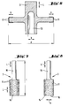
- the indicated machining tool 3 represents a rod-shaped or tubular tool which is equipped with cutting bodies 11 in its front area.
- Such tools are, for example, drills or drill bits for processing brittle materials.
- the tool is tuned acoustically, which creates a system bond.
- the tool 3 executes longitudinal vibrations in addition to the rotation.
- the ultrasonic support of the material-removing processing takes place in the direction of the contact pressure.
- FIGS. 2 and 3 For machining ductile failure materials with low contact pressure, tool vibrations in the direction of the contact pressure and cutting force are desirable.
- 11 cutouts 12 are provided in front of each cutting body, as seen in the cutting direction S.
- the cutting body 11 in Figs. 2 and 3 differ in that a cutting segment made of hard metal is indicated in FIG. 2, which extends approximately parallel to the cutting direction.
- the cutting body 11 is formed by a PCD cutting edge, which is arranged inclined to the cutting direction.
- the outer protrusion of the area carrying the cutting segments 11 is smaller than the inner protrusion I compared to the jacket of the cylindrical tool.
- the disk-shaped machining tool 3 shown in FIG. 5 has cutting bodies 11 with undefined cutting edges on the circumference and on the outer side regions, for example grains or splinters made of hard metal or diamond. Such tools are used, for example, in slot machining.
- the introduced longitudinal ultrasonic vibration L excites a bending mode on the pane.
- the disk is tuned in the axial direction to integer multiples of ⁇ / 2 the longitudinal mode of the ultrasound vibrations introduced.
- the disk diameter d is an integral multiple of half the wavelength of the excited bending mode.
- the tool 3 oscillates laterally to the cutting direction, which makes flushing easier.
- f r stands for the radial resonance frequency c L for the longitudinal sound velocity in the tool
- D M for the average diameter of the disk-shaped tool.
- a finger-shaped processing tool 3 for slot processing is shown. It has a stick-shaped insertion end 15 and one cylindrical body 14, on the outer surface of the cutting body 11 are arranged with undefined cutting edges. Its axial length I is matched to the introduced longitudinal vibrations of ⁇ / 2. The tool 3 oscillates laterally to the cutting direction, which facilitates flushing of the cutting area.
- a small eccentric mass of approximately 1-30 g is additionally arranged at the front end. Due to the small eccentric mass, the longitudinal vibration is converted into a bending mode. The tool vibrates in the direction of the contact pressure.
- FIG. 12 shows a cylindrical grinding tool 3 for surface processing in axial section.
- An axially extending grinding surface 19 with grinding bodies 11 with undefined cutting edges is arranged on its circumference.
- the tool has an axial bore 13 with a diameter b.
- the outer diameter of the roller-shaped tool 3 is provided with the reference symbol d.
- f r stands for the radial resonance frequency
- c L for the longitudinal speed of sound in the tool
- D M for the mean diameter of the cylindrical tool.
- the introduced longitudinal ultrasonic vibration is converted into radial waves V by transverse contractions in the tool designed in this way in the vibration node.
- the tool vibrates again in Direction of contact pressure.
- two or more such tools 3 are preferably arranged one behind the other.
- the structure of the hand-held device shown schematically in FIG. 13 largely corresponds to the device shown in FIG. 1. The difference is that the electroacoustic transducer 4 is designed to generate ultrasonic torsion waves with a wavelength ⁇ of approximately 5-20 cm.
- the tool itself is preferably equipped with PCD cutting edges or diamond segments.
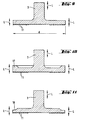
- Figs. 14 and 15 In the event that both vibration support in the direction of the cutting force and in the pressing direction is desired, as shown in Figs. 14 and 15 indicated, seen in the cutting direction S, 11 recesses 12 are provided behind the cutting body.
- the cutting body 11 in Figs. 14 and 15 differ in that a cutting segment made of hard metal is indicated in FIG. 14, which extends approximately parallel to the cutting direction, while in FIG. 15 the cutting body 11 is a PCD cutting edge which is arranged inclined with respect to the cutting direction.
- the disk-shaped machining tool 3 for slot machining shown in FIG. 16 has cutting bodies 11 with undefined cutting edges on its circumference and on its outer side regions.
- the washer is tuned in the axial direction to torsional vibrations of ⁇ / 2.
- the torsional vibrations introduced result in torsional vibrations of the disk 3 in the direction of the cutting force.
- the ratio of the diameter of the shaft carrying the disk and the disk can be up to approximately 1: 4.
- FIG. 17 shows a finger-shaped grinding tool 3 for slot machining, which has a stick-shaped insertion end 15 and a cylindrical body 14.
- Cutting bodies 11 with undefined cutting edges are arranged on the peripheral surface of the body 14.
- the ultrasound torsional vibrations introduced result in a torsional vibration of the tool in the cutting direction.
- the disk 18 shows a grinding tool 3 in the form of a cup or face plate.
- the disk On its underside facing away from the insertion end, the disk is equipped with cutting bodies 11 with undefined cutting edges.
- the ultrasonic torsional vibration introduced excites the disc to torsional vibrations. The disc thus swings in the direction of the cutting force.
- FIG. 19 shows a vibration amplifier 5 designed as a suction device in axial section. It is provided with an axial bore 20, into which approximately radially extending suction channels 21 open. The mouth areas 22 of the suction channels 21 are arranged in the area of vibration nodes of the generated ultrasonic vibrations. In the illustrated embodiment, the suction channels 21 open in the area of the bearings 7 and 8 of the rotatable vibration amplifier 5. The circumferential toothing 10 provided on the vibration amplifier 5 for the transmission of the driving force from the drive unit is also indicated. In an alternative and not shown embodiment variant, the vibration amplifier 5 can be preceded by a separate suction module and preferably connected to it in a rotationally fixed manner. The design of the suction module is analogous to the vibration amplifier 5 designed as a suction device. The cuttings sucked in via the axial bore 20 are discharged in the direction of arrow E through the radial suction channels 21 to a connected vacuum cleaner.
- the vibrations of the machining tool excited by ultrasonic vibrations support the abrasive or machining removal mechanism caused by the rotation of the machining tool by means of an additional dismantling mechanism in the form of a direct impact of the machining tool in the direction of the pressing force, the cutting force or laterally.
- the superimposition of two degradation mechanisms increases the degradation rate even further.
- the contact pressure to be applied by the user of the device is reduced.
- the noise and vibration pollution of the user of the hand-held device according to the invention is reduced by the ultrasound support compared to the hammer drilling devices.
- the wear on the machining tools used in the hand-held device for example due to friction or chemical interaction between the cutting edge of the machining tool and the workpiece, is reduced.
- the heat load on the cutting edge of the tool is reduced. This increases the service life of the handheld tool combination even further.
- the safety of the handheld machine tool combinations for grinding inserts is reduced by reducing the number of revolutions required Tools increased compared to the known grinding machines.
- the hand-held device according to the invention can be used in combination with the processing tools according to the invention for the material-removing processing of brittle materials as well as for the processing of ductile-failing materials, for example soft metals such as aluminum, copper etc.
- the improvements according to the invention also make it possible to further reduce the dust load on the user which occurs during the machining of materials
Abstract
Description
Die Erfindung betrifft ein Handgerät zur materialabtragenden Bearbeitung von spröden und/oder duktil versagenden Werkstoffen gemäss Oberbegriff des Patentanspruchs 1.The invention relates to a hand-held device for material-removing processing of brittle and / or ductile-failing materials according to the preamble of patent claim 1.
In der Bauindustrie, im Installations- und Elektrogewerbe usw. ist es vielfach nötig, Baustoffe wie Beton mit oder ohne Armierungseisen, Holz und Mauerwerk aber auch Metall materialabtragend zu bearbeiten, um auf diese Weise beispielsweise Durchbrüche oder Kanäle für Leitungen, Vertiefungen für das Anbringen von Steckerdosen u.v.a.m. zu erstellen. Bevorzugt werden dafür Handgeräte in Verbindung mit geeigneten Bearbeitungswerkzeugen eingesetzt. Derartige Handgeräte stellen beispielsweise die Handkembohrgeräte oder die Handgeräte zur Oberflächen- oder zur Schlitzbearbeitung der Anmelderin dar, die beispielsweise im Produktekatalog der Anmelderin, Systemlösungen für den Bau 1994/95, Seiten 92-95 bzw. Seiten 111-113 beschrieben sind. Während diese Handgeräte der Anmelderin ein sehr breites Anwendungsspektrum aufweisen und sich im Alltagseinsatz bei einer hohen Materialabbaurate bereits bewährt haben, besteht dennoch der Wunsch nach Verbesserungen.In the construction industry, in the installation and electrical industry, etc., it is often necessary to work on materials such as concrete with or without reinforcing iron, wood and masonry, but also metal, in order to remove openings or ducts for cables, recesses for attaching Sockets etc. to create. Handheld devices are preferably used in conjunction with suitable processing tools. Such hand-held devices are, for example, the hand-held drill drilling devices or the hand-held devices for surface or slot processing by the applicant, which are described, for example, in the applicant's product catalog, system solutions for construction 1994/95, pages 92-95 and pages 111-113. While these handheld devices from the applicant have a very wide range of applications and have already proven themselves in everyday use with a high material degradation rate, there is still a desire for improvements.
Insbesondere soll die Abbaurate noch weiter erhöht werden. Zugleich soll die vom Anwender des Gerätes aufzubringende Anpresskraft reduziert werden, um das Einsatzspektrum des Handgeräts noch ausdehnen zu können. Die Lärm- und Vibrationsbelastung des Anwenders durch das Handgerät soll noch weiter herabgesetzt werden. Der Verschleiss der im Handgerät eingesetzten Bearbeitungswerkzeuge, beispielsweise durch Reibung oder chemische Wechselwirkung zwischen der Schneide des Bearbeitungswerkzeuges und dem Werkstück, soll verringert werden. Die Wärmebelastung des Bearbeitungswerkzeugs an der Schneide soll reduziert werden. Die Standzeit der Handgerät - Werkzeug Kombination soll noch weiter erhöht werden. Das verbesserte Gerät soll in Kombination mit geeigneten Bearbeitungswerkzeugen für die materialabtragende Bearbeitung von spröden Werkstoffen wie auch für die Bearbeitung von duktil versagenden Werkstoffen, beispielsweise Weichmetallen wie Aluminium, Kupfer etc., einsetzbar sein. Durch die Verbesserung des Handgerätes soll auch die Möglichkeit geschaffen werden, die bei der materialabtragenden Bearbeitung von Werkstoffen auftretende Staubbelastung des Anwenders noch Weiter zu reduzieren.In particular, the degradation rate is to be increased even further. At the same time, the contact pressure to be applied by the user of the device is to be reduced in order to be able to expand the range of uses of the hand-held device. The noise and vibration exposure of the user from the handheld device should be reduced even further. The wear of the machining tools used in the hand-held device, for example due to friction or chemical interaction between the cutting edge of the machining tool and the workpiece, is to be reduced. The heat load on the machining tool on the cutting edge should be reduced. The service life of the handheld tool combination should be increased even further. The improved device is to be used in combination with suitable machining tools for the machining of brittle materials as well as for the machining of ductile materials such as soft metals Aluminum, copper, etc. can be used. The improvement of the hand-held device should also make it possible to further reduce the dust exposure of the user that occurs during material-removing processing of materials.
Der Erfindung liegt daher die Aufgabe zugrunde, ein Handgerät der gattungsgemässen Art im Hinblick auf die vorstehend geschilderten Anforderungen zu verbessern. Diese Aufgaben werden durch ein Handgerät zur materialabtragenden Bearbeitung von spröden und/oder duktil versagenden Werkstoffen gelöst, welches die im kennzeichnenden Teil des Patentanspruchs 1 angeführten Merkmale aufweist. Insbesondere sind bei dem gattungsgemässen Handgerät gemäss der Erfindung innerhalb des Gehäuses ein elektroakustischer Wandler für die Erzeugung von Ultraschallschwingungen und ein Schwingungsverstärker angeordnet, mit denen im Betrieb des Geräts der Rotation des Bearbeitungswerkzeugs Ultraschallschwingungen überlagerbar sind. Auf diese Weise wird der durch die Rotation des Bearbeitungswerkzeugs bedingte abrasive oder zerspanende Abbaumechanismus durch einen zusätzlichen Abbaumechanismus in Form eines direkten Stosses des Bearbeitungswerkzeugs unterstützt. Auf diese Weise steigt die Abbaurate gegenüber konventionellen Bearbeitungsmethoden ohne Ultraschallunterstützung stark, typischerweise um den Faktor 2-10 an. Zum Unterschied von konventionellen Hammerbohrgeräten nach dem schlagenden Prinzip, bei dem einzelne Spannungswellen durch das Bearbeitungswerkzeug laufen und dann abklingen, wird durch die Überlagerung von Ultraschallschwingungen im Bearbeitungswerkzeug eine stehende Welle aufrechterhalten, deren Energie in den abzutragenden Werkstoff eingeleitet wird.The invention is therefore based on the object of improving a hand-held device of the generic type with regard to the requirements described above. These tasks are solved by a hand-held device for material-removing processing of brittle and / or ductile-failing materials, which has the features stated in the characterizing part of patent claim 1. In particular, in the generic hand-held device according to the invention, an electroacoustic transducer for generating ultrasound vibrations and a vibration amplifier are arranged within the housing, with which ultrasound vibrations can be superimposed on the rotation of the processing tool during operation of the device. In this way, the abrasive or machining removal mechanism caused by the rotation of the processing tool is supported by an additional removal mechanism in the form of a direct impact of the processing tool. In this way, the rate of degradation rises sharply compared to conventional processing methods without ultrasound support, typically by a factor of 2-10. In contrast to conventional hammer drills based on the striking principle, in which individual voltage waves run through the machining tool and then subside, a standing wave is maintained by superimposing ultrasonic vibrations in the machining tool, the energy of which is introduced into the material to be removed.
Die Ultraschallunterstützung resultiert auch in einer deutlichen Reduktion der erforderlichen Anpresskraft. Dadurch können Handanwendungen auch auf Bereiche ausgedehnt werden, in denen derzeit noch auf konventionelle Weise mit stationären Geräten gearbeitet werden muss. Da durch die Ultraschallschwingungen die Reibung deutlich reduziert wird, entstehen an den Kontaktbereichen des Bearbeitungswerkzeugs mit dem abzutragenden Werkstoff kleinere Temperaturen. Die Reduktion der Reibung resultiert in einer geringeren Abrasion des Werkzeugs. Zugleich wird durch die niedrigeren Temperaturen auch die chemische Wechselwirlung zwischen dem Werzeug und dem Werkstück herabgesetzt. Dies wird auch noch durch den Effekt des Mikrohämmems unterstützt, da auf diese Weise die Kontaktzeit des Werkzeugs mit dem abzutragenden Werkstoff verringert wird. Auch wird der Kontaktbereich des Bearbeitungswerkzeugs mit dem Werkstoff durch das Mikrohämmem kaltverfestigt, was der längeren Standzeit des Werkzeugs zugute kommt. Die Erzeugung von Ultraschallwellen und die durch die Ultraschallwellen hervorgerufene Stosswirkung des Bearbeitungswerkzeugs sind nur mit einer geringen Lärm- und Vibrationsbelastung des Anwenders des Gerätes verbunden und ist deutlich niedriger als die Lärm- und Vibrationsbelastung bei konventionellen Handgeräten nach dem schlagenden Prinzip. Berücksichtigt man, dass das Hand - Arm System insbesondere im Bereich von 1-200 Hz besonders empfindlich ist, so ist unmittelbar einsichtig, dass Vibrationen im Ultraschallbereich vernachlässigbar sind.The ultrasound support also results in a significant reduction in the required contact pressure. As a result, manual applications can also be expanded to areas where stationary devices still have to be used in a conventional manner. Since the friction is significantly reduced by the ultrasonic vibrations, lower temperatures arise at the contact areas of the machining tool with the material to be removed. The reduction in friction results in less tool abrasion. At the same time, the lower temperatures also reduce the chemical interaction between the tool and the workpiece. This is also supported by the effect of the micro-hammer, since in this way the contact time of the tool with the material to be removed is reduced. The contact area of the machining tool with the material is also work hardened by the micro-hammer, which benefits the longer service life of the tool. The generation of Ultrasonic waves and the impact of the machining tool caused by the ultrasonic waves are associated only with a low level of noise and vibration for the user of the device and is significantly lower than the level of noise and vibration in conventional handheld devices based on the striking principle. If one takes into account that the hand - arm system is particularly sensitive in the range of 1-200 Hz, it is immediately clear that vibrations in the ultrasonic range are negligible.
Die Frequenz und die Amplitude der erzeugten Ultraschallwellen werden auf die Schnittgeschwindigkeit des Bearbeitungswerkzeugs abgestimmt und vorzugsweise derart eingestellt, dass gilt![]()
![]()
Vorzugsweise wird ein elektroakustischer Wandler gewählt, der eine Ultraschalleistung von etwa 100 W bis etwa 1000 W, vorzugsweise etwa 200 W bis etwa 500 W abgibt. Elektroakustische Wandler dieser Leistungsklasse haben ein ausgewogenes Verhältnis von Leistung zu Gewicht und Grösse und können gut in Handgeräten gewohnter Dimensionen untergebracht werden. Besonders bevorzugt sind dabei magnetostriktive oder piezoelektrische Wandler, die in den erforderlichen Leistungsklassen erhältlich sind, zuverlässig und weitgehend unempfindlich gegenüber den in den üblichen Einsatzgebieten herrschenden Handhabungsangewohnheiten sind.An electroacoustic transducer is preferably selected which emits an ultrasonic power of approximately 100 W to approximately 1000 W, preferably approximately 200 W to approximately 500 W. Electroacoustic transducers in this performance class have a balanced ratio of power to weight and size and can be easily accommodated in handheld devices of the usual dimensions. Particularly preferred are magnetostrictive or piezoelectric transducers, which are available in the required performance classes, are reliable and largely insensitive to the handling habits prevailing in the usual fields of application.
Das Bearbeitungswerkzeug ist bevorzugt in einer Werkzeugaufnahme gehaltert, die im wesentlichen im Bereich eines Schwingungsknotens der erzeugten Ultraschallschwingungen angeordnet ist. In diesen Bereichen liegt die Energie der erzeugten Ultraschallschwingungen weitgehend als potentielle Energie vor. Dadurch ist der Einsteckbereich des Bearbeitungswerkzeugs von Vibrationsbelastungen weitgehend entkoppelt. Vorzugsweise sind die Fügestellen der einzelnen Komponenten des elektroakustischen Wandlers und des Schwingungsvemtärkers in Bereichen von Schwingungsknoten der erzeugten Ultraschallschwingungen angeordnet. Wie für den Fall der Werkzeugaufnahme gilt auch hier, dass die Energie der Ultraschallschwingungen in diesen Bereichen weitgehend als potentielle Energie vorliegt, so dass die Fügestellen keinen Längs- oder Querbelastungen ausgesetzt sind, die in unerwünschten Relativbewegungen der Einzelkomponenten zueinander resultieren könnten.The processing tool is preferably held in a tool holder, which is arranged essentially in the region of a vibration node of the generated ultrasonic vibrations. In these areas, the energy of the generated ultrasonic vibrations is largely available as potential energy. As a result, the insertion area of the machining tool is largely decoupled from vibration loads. The joints of the individual components of the electroacoustic transducer and of the vibration amplifier are preferably arranged in areas of vibration nodes of the generated ultrasonic vibrations. As for that In the case of the tool holder, it also applies here that the energy of the ultrasonic vibrations is largely present as potential energy in these areas, so that the joints are not exposed to any longitudinal or transverse loads which could result in undesired relative movements of the individual components with respect to one another.
Die Länge des am Handgerät befestigbaren Bearbeitungswerkzeugs ist vorzugsweise derart bemessen, dass am mit dem zu bearbeitenden Werkstoff in Kontakt tretenden Bereich ein Schwingungsbauch der erzeugten Ultraschallschwingungen anliegt. Auf diese Weise liegt am mit dem abzutragenden Werkstoff in Kontakt kommenden Bereich des Bearbeitungswerkzeugs die Energie der Ultraschallschwingung im wesentlichen nur in Form von kinetischer Energie vor und kann für die stossende Bearbeitung des Werkstoffs eingesetzt werden.The length of the processing tool that can be attached to the hand-held device is preferably dimensioned such that an antinode of the generated ultrasonic vibrations is present in the area that comes into contact with the material to be processed. In this way, the energy of the ultrasonic vibration is essentially only in the form of kinetic energy in the area of the machining tool that comes into contact with the material to be removed and can be used for the impact machining of the material.
Als Material für das Bearbeitungswerkzeug werden Materialien bevorzugt, die eine geringe Dämpfung gegenüber den Ultraschallschwingungen aufweisen. Vorzugsweise wird ein gehärteter Kohlenstoffstahl oder eine Aluminium- oder Titanlegierung verwendet, welche Materialien neben den geringen Dämpfungseigenschaften gegenüber von Ultraschallschwingungen die erforderlichen Festigkeiten aufweisen.Materials that have low damping compared to the ultrasonic vibrations are preferred as the material for the machining tool. A hardened carbon steel or an aluminum or titanium alloy is preferably used, which materials have the required strengths in addition to the low damping properties with respect to ultrasonic vibrations.
Die überlagerte rotatorische und translatorische Bewegung des Bearbeitungswerkzeugs wird vorzugsweise dadurch realisiert, dass der Schwingungsverstärker innerhalb des Gehäuses drehbar gelagert ist und mit Hilfe der elektrischen Antriebsmittel um seine Längsachse rotierbar ist. Dabei ist die Werkzeugaufnahme am Schwingungsverstärker vorgesehen. Auf diese Weise kann die Energie der Ultraschallschwingungen direkt vom Schwingungsverstärker in das Bearbeitungswerkzeug eingekoppelt werden. Verluste durch Zwischenstücke entfallen.The superimposed rotary and translatory movement of the machining tool is preferably realized in that the vibration amplifier is rotatably mounted within the housing and can be rotated about its longitudinal axis with the aid of the electrical drive means. The tool holder is provided on the vibration amplifier. In this way, the energy of the ultrasonic vibrations can be coupled directly from the vibration amplifier into the machining tool. There are no losses due to intermediate pieces.
In einer bevorzugten Ausführungsvariante der Erfindung ist der elektroakustische Wandler zur Erzeugung von longitudinalen Ultraschallschwingungen der Wellenlänge λ von etwa 10 bis 40 cm ausgebildet. Durch diese Wahl der Wellenlänge können noch Bearbeitungswerkzeuge einer vernünftigen Baulänge für Handanwendungen eingesetzt werden. Die Gesamtbaulänge des Handgeräts inklusive Bearbeitungswerkzeug sollte dabei mindestens das Dreifache der halben Wellenlänge der erzeugten Ultraschallschwingung betragen. Die maximale Gesamtbaulänge des erfindungsgemässen Handgeräts sollte 10•λ/2 nicht überschreiten.In a preferred embodiment of the invention, the electroacoustic transducer is designed to generate longitudinal ultrasonic vibrations of wavelength λ of approximately 10 to 40 cm. With this choice of wavelength, processing tools of a reasonable length can still be used for manual applications. The overall length of the handheld device including the processing tool should be at least three times the half wavelength of the ultrasonic vibration generated. The maximum overall length of the hand-held device according to the invention should not exceed 10 λ / 2.
Eine bevorzugte Ausführungsvariante eines Bearbeitungswerkzeugs für den Einsatz in Verbindung mit longitudinalen Ultraschallschwingungen ist ein rohr- oder stabförmiges Werkzeug der Länge nλ/2 mit n = 1, 2, 3, ... ist, welches an seinem vorderen Ende mit Schneidkörpern bestückt ist. Im Betrieb führt das Werkzeug longitudinale Schwingungen aus, die in Richtung der Anpresskraft wirken. Ein erfindungsgemässes Handgerät mit einem derartigen Bearbeitungswerkzeug kann beispielsweise anstelle einer konventionellen Hammerbohrmaschine eingesetzt werden. Der elektroakustische Wandler für longitudinale Ultraschallschwingungen übernimmt dabei die Funktion eines elektropneumatischen Schlagwerks. Die erfindungsgemäss ausgestatteten Geräte können insbesondere auch zum Erstellen von Mauerdurchbrüchen eingesetzt werden. Derzeit existiert für diesen Einsatzzweck eine separate Gerätelinie, die in Verbindung mit Bohrkronen zur Anwendung kommt.A preferred embodiment variant of a processing tool for use in connection with longitudinal ultrasonic vibrations is a tubular or rod-shaped tool of length nλ / 2 with n = 1, 2, 3, ..., which is equipped with cutting bodies at its front end. In operation, the tool performs longitudinal vibrations that act in the direction of the contact pressure. A hand-held device according to the invention with such a processing tool can be used, for example, instead of a conventional hammer drill. The electroacoustic transducer for longitudinal ultrasonic vibrations takes on the function of an electro-pneumatic hammer mechanism. The devices equipped according to the invention can in particular also be used to create wall openings. There is currently a separate line of equipment for this purpose, which is used in conjunction with drill bits.
Zur Bearbeitung von duktil versagenden Werkstoffen sind am Bearbeitungswerkzeug in Schnittrichtung gesehen, vor jedem Schneidkörper Ausnehmungen vorgesehen. Auf diese Weise kann die in das Werkzeug eingeleitete longitudinale Ultraschallschwingung in Richtung der Schnittkraft umgelenkt werden, um derart sowohl eine Schwingungsunterstützung in Richtung der Anpresskraft wie auch in Richtung der Schnittkraft zu erzielen. Dadurch wird die erforderliche Anpresskraft reduziert.For machining ductile failure materials, recesses are provided in front of each cutting body on the machining tool in the cutting direction. In this way, the longitudinal ultrasonic vibration introduced into the tool can be deflected in the direction of the cutting force in order to achieve vibration support in the direction of the contact pressure as well as in the direction of the cutting force. This reduces the contact pressure required.
Durch die Austattung eines rohrförmigen Bearbeitungswerkzeugs mit Schneidkörpem, die mit asymmetrischen Ueberständen am Vorderende des Werkzeugs angeordnet sind, kann die longitudinale Ultraschallschwingung bei der Rotation des Werkzeugs etwa radial nach aussen und oben umgelenkt werden. Auf diese Weise kann insbesondere bei mit Schneidsegmenten besetzten Bohrkronen die Spülwirkung verbessert werden.By equipping a tubular machining tool with cutting bodies which are arranged at the front end of the tool with asymmetrical protrusions, the longitudinal ultrasonic vibration can be deflected approximately radially outwards and upwards when the tool is rotated. In this way, the flushing effect can be improved, in particular in the case of drill bits with cutting segments.
Ein bevorzugtes scheibenförmiges Bearbeitungswerkzeug besitzt einen Aussendurchmesser und weist an seinem Umfang und an den äusseren seitlichen Randbereichen Schneidkörper auf. Seine axiale Erstreckung beträgt nλ/2 mit n = 1, 2, 3. In seinem zentralen Bereich weist das scheibenförmige Bearbeitungswerkzeug eine axiale Bohrung eines bestimmten Durchmessers auf, wobei das Werkzeug einen mittleren Durchmesser aufweist, der als die Hälfte der Summe des Aussendurchmessers des Werkzeugs und des Innendurchmessers der axialen Bohrung definiert ist. Vorzugsweise ist das Bearbeitungswerkzeug gemäss der Gleichung![]()
![]()
Ein bevorzugtes Bearbeitungswerkzeug für die Schlitzbearbeitung ist ein scheibenförmiges Werkzeug, welches an seinem Umfang und an den äusseren seitlichen Randbereichen Schneidkörper aufweist, und dessen axiale Erstreckung nλ/2 mit n=1, 2, 3, ... beträgt. Die longitudinalen Ultraschallschwingungen induzieren auf der Scheibe Biegewellen. Die kinetische Energie der Biegewellen hat dann ihr Maximum am Umfang der Scheibe, wenn der Aussendurchmesser der Scheibe ein ganzzahliges Vielfaches der halben Wellenlänge der Biegewellen auf dem scheibenförmigen Werkzeug beträgt. Auf diese Weise wird die Schlitzbearbeitung durch Lateralwellen unterstützt, die von den longitudinalen Ultraschallwellen induziert werden. Dadurch kann die erforderliche Umdrehungsgeschwindigkeit der Scheibe deutlich reduziert werden, was die Arbeitssicherheit erhöht und Lärmemissionen vermindert.A preferred machining tool for slot machining is a disk-shaped tool which has cutting bodies on its circumference and on the outer lateral edge regions, and whose axial extension is nλ / 2 with n = 1, 2, 3, ... The longitudinal ultrasonic vibrations induce bending waves on the disc. The kinetic energy of the bending shafts then has its maximum at the circumference of the disk if the outside diameter of the disk is an integral multiple of half the wavelength of the bending shafts on the disk-shaped tool. In this way, slot machining is supported by lateral waves induced by the longitudinal ultrasonic waves. As a result, the required rotational speed of the disk can be significantly reduced, which increases occupational safety and reduces noise emissions.
Ein fingerförmiges Schleifwerkzeug weist eine etwa zylinderförmige Gestalt auf. Der Aussenmantel des Zylinders ist zur Schlitzbearbeitung mit Schleifkörpern besetzt. Seine axiale Länge beträgt ein ganzzahliges Vielfaches der halben Wellenlänge der eingeleiteten longitudinalen Ultraschallschwingungen. Die Schwingung des Bearbeitungswerkzeugs erfolgt lateral zur Schnittrichtung, was unter anderem auch die Spülung erleichtert. Zudem kann durch die Ultraschallunterstützung die Umdrehungsgeschwindigkeit des Werkzeugs deutlich reduziert werden, was die Arbeitssicherheit erhöht und die Lärmemissionen vermindert. In einer Variante dieses Bearbeitungswerkzeugs wird die longitudinale Ultraschallschwingung in eine Biegemode des Werkzeugs umgewandelt. Dies erfolgt beispielsweise durch die Anordnung einer kleinen exzentrischen Masse am vorderen Ende des Werkzeugs. Dadurch erfolgt eine Schwingung in Richtung der Anpresskraft, wodurch die erforderliche Anpresskraft noch weiter herabgesetzt wird.A finger-shaped grinding tool has an approximately cylindrical shape. The outer surface of the cylinder is equipped with grinding tools for slot machining. Its axial length is an integral multiple of half the wavelength of the introduced longitudinal ultrasonic vibrations. The machining tool vibrates laterally to the cutting direction, which among other things also facilitates flushing. In addition, the speed of rotation of the tool can be significantly reduced by the ultrasound support, which increases work safety and reduces noise emissions. In a variant of this machining tool, the longitudinal ultrasonic vibration is converted into a bending mode of the tool. This is done, for example, by arranging a small eccentric mass at the front end of the tool. This causes an oscillation in the direction of the contact pressure, which further reduces the required contact force.
Ein bevorzugtes Bearbeitungswerkzeug ist ein Schleifwerkzeug in Form einer Topf- oder Planscheibe, welche an ihrem mit dem zu bearbeitenden Werkstoff in Kontakt tretenden Bereich mit Schleifkörpem ausgestattet ist. Die axiale Erstreckung des Werkzeugs beträgt nλ/2 mit n=1, 2, 3, ... , der Durchmesser ein ganzzahliges Vielfaches der halben Wellenlänge von Biegeschwingungen beträgt, welche durch die longitudinalen Ultraschallschwingungen im scheibenförmigen Schleifwerkzeug angeregt werden. Die Schwingung des Werkzeugs erfolgt somit in Richtung der Anpresskraft, welche dadurch reduziert werden kann. Durch die Ultraschallunterstützung kann die Drehzahl des Werkzeugs deutlich verringert werden. Dadurch wird die Reibungswärme vermindert. Zudem unterstützen die induzierten Biegewellen auch die Spülung. Die Schnittgeschwindigkeit des Werkzeugs nimmt mit dem Radius zu. Um den Effekt des Mikromeisselns noch weiter zu verstärken, werden die Ränder des scheibenförmigen Bearbeitungswerkzeugs dicker oder dünner gestaltet als der übrige Bereich der Scheibe. Auf diese Weise wird die Amplitude der induzierten Biegeschwingungen verstärkt, was dem Effekt des Mikromeisselns unmittelbar zugute kommt.A preferred processing tool is an abrasive tool in the form of a cup or face plate, which is equipped with abrasive bodies on its area that comes into contact with the material to be machined. The axial extent of the tool is nλ / 2 with n = 1, 2, 3, ..., the diameter is an integral multiple of half the wavelength of bending vibrations which are excited by the longitudinal ultrasonic vibrations in the disc-shaped grinding tool. The tool vibrates in the direction of the contact pressure, which can be reduced. The speed of the tool can be significantly reduced by the ultrasound support. This reduces the frictional heat. The induced bending waves also support the flushing. The cutting speed of the tool increases with the radius. In order to further intensify the effect of micro-chiseling, the edges of the disk-shaped machining tool are made thicker or thinner than the rest of the area of the disk. In this way, the amplitude of the induced bending vibrations is increased, which directly benefits the effect of micro chiseling.
Ein weiteres bevorzugtes Bearbeitungswerkzeug zum Einsatz mit einem Handgerät für die Überlagerung von longitudinalen Ultraschallschwingungen ist ein walzenförmiges Schleifwerkzeug, an dessen Umfang eine axiale Schleiffläche mit Schleifkörpern angeordnet ist. Die axiale Erstreckung des Werkzeugs beträgt nλ/2 mit n=1, 2, 3 ... . Das Werkzeug besitzt eine axiale Bohrung eines bestimmten Durchmessers, wobei das Werkzeug einen mittleren Durchmesser aufweist, der als die Hälfte der Summe des Aussendurchmessers des Werkzeugs und des Innendurchmessers der axialen Bohrung definiert ist und gemäss der Gleichung![]()
![]()
In einer Variante des erlindungsgemässen Handgeräts zur materialabtragenden Bearbeitung von spröden und/oder duktil versagenden Werkstoffen ist der elektroakustische Wandler zur Erzeugung von Ultraschall - Torsionsschwingungen ausgebildet. Die Wellenlänge λ der erzeugten Torsionsschwingungen im Ultraschallbereich beträgt etwa 10 bis 40 cm. Durch diese Wahl der Wellenlänge können noch Bearbeitungswerkzeuge einer vernünftigen Baulänge für Handanwendungen eingesetzt werden. Die Gesarntbaulänge des Handgeräts inklusive Bearbeitungswerkzeug sollte dabei mindestens das Dreifache der halben Wellenlänge der erzeugten Ultraschallschwingung betragen. Die maximale Gesamtbaulänge des erfindungsgemässen Handgeräts sollte 10•λ/2 nicht überschreiten.In a variant of the hand-held device according to the invention for material-removing processing of brittle and / or ductile-failing materials, the electroacoustic transducer is designed to generate ultrasonic torsional vibrations. The wavelength λ of the torsional vibrations generated in the ultrasound range is approximately 10 to 40 cm. With this choice of wavelength, processing tools of a reasonable length can still be used for manual applications. The overall length of the handheld device, including the processing tool, should be at least three times half the wavelength of the ultrasonic vibration generated. The maximum overall length of the hand-held device according to the invention should not exceed 10 λ / 2.
Ein bevorzugtes Bearbeitungswerkzeug, das im Einsatz mit Ultraschall - Torsionsschwingungen unterstützt wird, ist ein rohr- oder stabförmiges Werkzeug der Länge nλ/2 mit n=1, 2, 3, ... , welches an seinem vorderen Ende mit Schneidkörpem bestückt ist. Auf diese Weise erfolgt die Ultraschallunterstützung in Richtung der Schnittkraft, wobei aufgrund der gewählten Baulänge des Bearbeitungswerkzeugs gewährleistet ist, dass am mit dem abzutragenden Werkstoff in Kontakt tretenden Bereich des Werkzeugs die Energie der Ultraschallschwingung im wesentlichen als kinetische Energie anliegt. Das derart ausgebildete Werkzeug in Verbindung mit dem Ultraschall - Torsionsschwingungen erzeugenden Handgerät ist für die Bearbeitung duktil versagender Werkstoffe, beispielsweise Aluminium-Verbundkonstruktionen, und spröder Werkstoffe geeignet, wobei durch die Ultraschallunterstützung in Richtung der Schneidkraft die Abtragrate deutlich erhöht wird.A preferred machining tool that is supported in use with ultrasonic torsional vibrations is a tubular or rod-shaped tool of length nλ / 2 with n = 1, 2, 3, ..., which is equipped with cutting bodies at its front end. In this way, the ultrasound is supported in the direction of the cutting force, and the selected length of the machining tool ensures that the energy of the ultrasound oscillation is essentially present as kinetic energy in the region of the tool that comes into contact with the material to be removed. The tool designed in this way in conjunction with the hand-held device that generates ultrasonic torsional vibrations is suitable for processing ductile failure materials, for example aluminum composite structures, and brittle materials, the removal rate being significantly increased by the ultrasonic support in the direction of the cutting force.
Bei einem bevorzugten Bearbeitungswerkzeug sind in Schnittrichtung gesehen, hinter jedem Schneidkörper Ausnehmungen vorgesehen. Auf diese Weise können Torsionsschwingungen derart umgelenkt werden, dass neben den Schwingungen in Richtung der Schnittkraft auch eine Schwingungsunterstützung in Richtung der Anpresskraft erfolgt. Mit derart ausgebildeten Bearbeitungswerkzeugen, beispielsweise Bohrkronen, wird die erforderliche Anpresskraft deutlich reduziert.In a preferred machining tool, recesses are provided behind each cutting body, as seen in the cutting direction. In this way, torsional vibrations can be deflected such that, in addition to the vibrations in the direction of the cutting force, there is also vibration support in the direction of the contact pressure. The processing pressure required is significantly reduced with machining tools designed in this way, for example drill bits.
Im Falle von scheibenförmigen Bearbeitungswerkzeugen, welche an ihrem Umfang und an den äusseren seitlichen Randbereichen Schneidkörper aufweisen und beispielsweise für die Schlitzbearbeitung einsetzbar sind, beträgt die axiale Erstreckung des Werkzeugs nλ/2 mit n=1, 2, 3 ... . Durch das Einleiten von Torsionswellen erfolgt eine Unterstützung in Richtung der Schnittkraft. Dadurch kann bei gleich guter Abbauleistung die Umdrehungszahl des scheibenförmigen Werkzeugs reduziert werden, was Arbeitssicherheit erhöht und Lärmemissionen verringert. In einer besonders bevorzugten Ausführungsvariante des scheibenförmigen Bearbeitungswerkzeugs beträgt der maximale Scheibendurchmesser bis etwa das Vierfache des Durchmessers der die Scheibe tragenden Welle. Bei diesen Durchmesserverhältnissen ist die Ultraschallunterstützung der Abbauleistungen des Werkzeugs besonders gut.In the case of disk-shaped machining tools which have cutting bodies on their circumference and on the outer lateral edge regions and can be used, for example, for slot machining, the axial extent of the tool is nλ / 2 with n = 1, 2, 3 .... The introduction of torsion waves provides support in the direction of the cutting force. As a result, the number of revolutions of the disk-shaped tool can be reduced, with the same good removal performance Occupational safety increased and noise emissions reduced. In a particularly preferred embodiment variant of the disk-shaped machining tool, the maximum disk diameter is up to approximately four times the diameter of the shaft carrying the disk. With these diameter ratios, the ultrasound support of the removal performance of the tool is particularly good.
In einer bevorzugten Ausführungsvariante des erlindungsgemässen Handgeräts ist der Schwingungsverstärker mit einer durchgehenden Axialbohrung versehen, in welche radiale Absaugkanäle münden. Die Mündungen der Absaugkanäle sind im wesentlichen im Bereich von Schwingungsknoten der im Betrieb erzeugten Ultraschallschwingungen angeordnet. An die Absaugkanäle ist ein Staubsauger anschliessbar. Auf diese Weise ist die Voraussetzung geschaffen, das erzeugte Bohrklein durch die axiale Bohrung nach aussen abzuführen. In einer altemativen Ausführungsvariante ist dem Schwingungsverstärker ein Absaugmodul vorgelagert, welches die Länge nλ/2 mit n= 1, 2, 3 ..., insbesondere λ/2, aufweist. Das Absaugmodul ist mit einer durchgehenden Axialbohrung versehen, in welche radiale Absaugkanäle münden. Die Mündungen der Absaugkanäle sind im wesentlichen im Bereich von Schwingungsknoten der im Betrieb erzeugten Ultraschallschwingungen angeordnet. An die Absaugkanäle ist ein Staubsauger anschliessbar.In a preferred embodiment variant of the hand-held device according to the invention, the vibration amplifier is provided with a continuous axial bore into which radial suction channels open. The mouths of the suction channels are arranged essentially in the area of vibration nodes of the ultrasonic vibrations generated during operation. A vacuum cleaner can be connected to the suction channels. In this way, the prerequisite is created for the drill cuttings to be discharged to the outside through the axial bore. In an alternative embodiment, the vibration amplifier is preceded by a suction module which has the length nλ / 2 with n = 1, 2, 3 ..., in particular λ / 2. The suction module is provided with a continuous axial bore into which radial suction channels open. The mouths of the suction channels are arranged essentially in the area of vibration nodes of the ultrasonic vibrations generated during operation. A vacuum cleaner can be connected to the suction channels.
Im folgenden wird die Erfindung unter Bezugnahme auf die schematischen Darstellungen noch näher erläutert. Die Darstellungen beschränken sich dabei auf die für das Verständnis der Erfindung erforderlichen Einzelheiten. Es zeigen:
- Fig. 1
- ein Ausführungsbeispiel eines erfindungsgemässen Handgerätes für longitudinale Ultraschallschwingungen mit eingespanntem Bearbeitungswerkzeug,
- Figs. 2 - 12
- teilweise Detail- und Schnittdarstellungen von Bearbeitungswerkzeugen zum Einsatz in Verbindung mit einem Handgerät für longitudinale Ultraschallschwingungen,
- Fig. 13
- ein Ausführungsbeispiel eines erfindungsgemässen Handgerätes für Ultraschall - Torsionsschwingungen mit eingespanntem Bearbeitungswerkzeug
- Figs. 14 -18
- teilweise Detaildarstellungen von Bearbeitungswerkzeugen zum Einsatz in Verbindung mit einem Handgerät für Ultraschall - Torsionsschwingungen und
- Fig. 19
- einen Axialschnitt eines als Absaugeinrichtung ausgebildeten Schwingungsverstärkers.
- Fig. 1
- 1 shows an exemplary embodiment of a hand-held device according to the invention for longitudinal ultrasonic vibrations with a clamping tool,
- Figs. 2 - 12
- partially detailed and sectional representations of processing tools for use in connection with a handheld device for longitudinal ultrasonic vibrations,
- Fig. 13
- an embodiment of a handheld device according to the invention for ultrasonic torsional vibrations with a clamped machining tool
- Figs. 14-18
- partially detailed representations of processing tools for use in connection with a handheld device for ultrasonic torsional vibrations and
- Fig. 19
- an axial section of a vibration amplifier designed as a suction device.
Das in Fig. 1 beispielsweise dargestellte Handgerät für die materialabtragende Bearbeitung von spröden und/oder duktil versagenden Werkstoffen weist ein Gehäuse 1 auf, in dem eine mit dem Bezugszeichen 2 versehene Antriebseinheit für ein mit dem Handgerät verbundenes Bearbeitungswerkzeug 3. Im Betrieb wird das Bearbeitungswerkzeug 3 durch die Antriebseinheit in axiale Rotation versetzt, um den abzutragenden Werkstoff zu bearbeiten. Innerhalb des Gehäuses 1 sind ein elektroakustischer Wandler 4 für die Erzeugung von Ultraschallschwingungen und ein Schwingungsverstärker 5 angeordnet. Im Betrieb des Handgerätes sind auf diese Weise der Rotation des Bearbeitungswerkzeugs Ultraschallschwingungen überlagerbar. Vorzugsweise sind der elektroakustische Wandler 4 und der Schwingungsverstärker 5 in axialer Verlängerung des Bearbeitungswerkzeugs 3 angeordnet. Auf diese Weise können die erzeugten Ultraschallschwingungen direkt in das jeweilige Bearbeitungswerkzeug eingekoppelt werden; es sind keine Umlenkeinrichtungen für die erzeugten Schwingungen erforderlich, welche zu Verlusten an Schwingungsenergie führen könnten.The hand-held device shown in FIG. 1, for example, for the material-removing machining of brittle and / or ductile-failing materials has a housing 1 in which a drive unit provided with the
Die einzelnen Bauelemente des elektroakustischen Wandlers 4 und des Schwingungsverstärkers 5 sind in ihrer axialen Länge vorzugsweise derart bemessen, dass die Fügestellen in Bereichen von Schwingungsknoten der erzeugten Ultraschallschwingungen angeordnet sind. Das Bearbeitungswerkzeug 3 ist in einer Werkzeugaufnahme 6 gehaltert, welche sich vorzugsweise gleichfalls im wesentlichen im Bereich eines Schwingungsknotens der erzeugten Ultraschallschwingungen befindet. In den Schwingungsknoten der Ultraschallschwingungen liegt die Schwingungsenergie im wesentlichen als potentielle Energie vor. Dadurch kommt es nur zu geringen mechanischen Beanspruchungen der dort angeordneten Elemente.The axial length of the individual components of the
Die Antriebseinheit kann, wie dargestellt, unterhalb des elektroakustischen Schwingungswandlers 4 und des Schwingungsverstärkers 5 angeordnet sein, sie könnte aber auch im Griffteil des Gehäuses 1 untergebracht sein. Bei der in Fig. 1 dargestellten Ausührungsvariante des erfindungsgemässen Handgeräts ist der Schwingungsverstärker 5 drehbar gelagert, wie durch die Lager 7 und 8 angedeutet ist.The drive unit can, as shown, be arranged below the
Ein schematisch angedeutetes Antriebsritzel 9 greift in eine am Schwingungsverstärker 5 angebrachte Umfangsverzahnung 10 ein und versetzt diesen im Betrieb in axiale Rotation. Die Lagerung des Schwingungsverstärkers 5 ist vorzugsweise im Bereich von Schwingungsknoten der erzeugten Ultraschallschwingungen angeordnet, um die mechanische Belastung möglichst gering zu halten. Die Werkzeugaufnahme 6 ist direkt am Vorderende des Schwingungsverstärkers 5 vorgesehen. Sie kann als separate Einheit ausgebildet sein, vorzugsweise ist sie am Schwingungsverstärker 5 integriert. Der elektroakustische Wandler 4 ist mit dem Schwingungsverstärker 5 drehfest verbunden.A schematically indicated
Als elektroakustische Wandler werden magnetostriktive oder piezoelektrische Wandler eingesetzt. Die abgegebene Ultraschalleistung des elektroakustischen Wandlers liegt bei etwa 100 - 1000 W, bevorzugt bei etwa 200 - 500 W. Der elektroakustische Wandler kann ein Wandler für die Erzeugung von longitudinalen Ultraschallschwingungen sein, wie in Fig. 1 durch den Doppelpfeil L angedeutet, er kann aber auch ein Wandler für die Erzeugung von Ultraschall - Torsionsschwingungen sein. Der letztere Fall ist in Fig. 13 durch den Doppelpfeil T angedeutet.Magnetostrictive or piezoelectric transducers are used as electroacoustic transducers. The emitted ultrasound power of the electroacoustic transducer is approximately 100-1000 W, preferably approximately 200-500 W. The electroacoustic transducer can be a transducer for generating longitudinal ultrasonic vibrations, as indicated by the double arrow L in FIG. 1, but it can can also be a transducer for the generation of ultrasonic torsional vibrations. The latter case is indicated in FIG. 13 by the double arrow T.
Durch die Überlagerung von Ultraschallwellen wird der durch die Rotation des Bearbeitungswerkzeugs bedingte abrasive oder zerspanende Abbaumechanismus durch einen zusätzlichen Abbaumechanismus in Form eines direkten Stosses des Bearbeitungswerkzeugs unterstützt. Auf diese Weise steigt die Abbaurate gegenüber konventionellen Bearbeitungsmethoden ohne Ultraschallunterstützung stark, typischerweise um den Faktor 2-10 an. Zum Unterschied von konventionellen Hammerbohrgeräten nach dem schlagenden Prinzip, bei dem einzelne Spannungswellen durch das Bearbeitungswerkzeug laufen und dann abklingen, wird durch die Überlagerung von Ultraschallschwingungen im Bearbeitungswerkzeug eine stehende Welle aufrechterhalten, deren Energie in den abzutragenden Werkstoff eingeleitet wird. Im Fall von Bearbeitungswerkzeugen mit definierten Schneiden, beispielsweise Hartmetallschneiden oder polykristallinen Diamantschneiden (PKD) wird durch die Ultraschallunterstützung die Eindringtiefe der am abzutragenden Werkstoff angreifenden Schneide erhöht. Für die Erzielung einer der Bearbeitung ohne Ultraschallunterstützung vergleichbaren Eindringtiefe der Schneide kann daher die Anpresskraft reduziert werden. Dadurch wird bei vergleichbarer Eindringtiefe der Verschleiss der Schneide deutlich verringert. Dadurch können viele Werkstoffe mit Schneiden geringerer Härte bearbeitet werden, was die Werkzeugkosten unmittelbar beeinflusst. Bei undefinierten Schneiden, beispielsweise bei Schneidsegmenten aus Hartmetall oder Diamant oder bei Schleifschichten wird durch die Ultraschallunterstützung die bei der materialabtragenden Bearbeitung auftretende Wärme reduziert. Dies erweitert den Bereich von Trockenanwendungen von Handgeräten. Die erforderlichen Anpresskräfte werden deutlich reduziert. Die Selbstschärfung der Schneidsegmente wird unterstützt und erfolgt auch bei geringen Anpresskräflen. All dies resultiert in einer Erhöhung der Standzeit des Bearbeitungswerkzeugs und des Handgeräts, das durch die Ultraschallunterstützung einer geringeren mechanischen Belastung ausgesetzt ist.The superposition of ultrasound waves supports the abrasive or machining degradation mechanism caused by the rotation of the machining tool by means of an additional degradation mechanism in the form of a direct impact of the machining tool. In this way, the rate of degradation rises sharply compared to conventional processing methods without ultrasound support, typically by a factor of 2-10. In contrast to conventional hammer drills based on the striking principle, in which individual voltage waves run through the machining tool and then decay, a superimposed ultrasonic vibration in the machining tool maintains a standing wave, the energy of which is introduced into the material to be removed. In the case of machining tools with defined cutting edges, for example hard metal cutting edges or polycrystalline diamond cutting edges (PCD), the depth of penetration of the cutting edge attacking the material to be removed is increased by the ultrasound support. The contact pressure can therefore be reduced in order to achieve a depth of penetration comparable to machining without ultrasound support. This significantly reduces the wear on the cutting edge with a comparable penetration depth. This means that many materials with cutting edges of lower hardness can be machined, which has a direct impact on tool costs. In the case of undefined cutting edges, for example cutting segments made of hard metal or diamond or grinding layers, the Ultrasound support reduces the heat that occurs during material-removing processing. This extends the range of dry applications of handheld devices. The required contact forces are significantly reduced. The self-sharpening of the cutting segments is supported and takes place even with low contact forces. All of this results in an increase in the service life of the machining tool and the hand-held device, which is subjected to less mechanical stress due to the ultrasound support.
Bei den in den Figs. 1 - 12 beispielsweise und teilweise in schematischer Detailansicht dargestellten Bearbeitungswerkzeugen handelt es sich um Werkzeuge zum Einsatz in Verbindung mit einem Handgerät, das für die Erzeugung von longitudinalen Ultraschallschwingungen ausgestattet ist. Das in Fig. 1 dargestellte Handgerät weist einen elektroakustischen Wandler 4 auf, der zur Erzeugung von longitudinalen Ultraschallschwingungen der Wellenlänge λ von etwa 2-20 cm ausgelegt ist. Das angedeutete Bearbeitungswerkzeug 3 steht stellvertretend für ein stab- oder rohrtörmiges Werkzeug, welches in seinem vorderen Bereich mit Schneidkörpern 11 ausgestattet ist. Derartige Werkzeuge sind beispielsweise Bohrer oder Bohrkronen für die Bearbeitung spröder Werkstoffe. Die Länge 1 des Werkzeugs ist nλ/2, mit n=1,2,3,... . Das Werkzeug wird akustisch abgestimmt, wodurch Systembindung gegeben ist. Im Betrieb führt das Werkzeug 3 zusätzlich zur Rotation longitudinale Schwingungen aus. Die Ultraschallunterstützung der materialabtragenden Bearbeitung erfolgt in Richtung der Anpresskraft.With the in Figs. 1-12, for example, and partially shown in a schematic detailed view, processing tools are tools for use in connection with a hand-held device which is equipped for the generation of longitudinal ultrasonic vibrations. The hand-held device shown in FIG. 1 has an
Zur Bearbeitung von duktil versagenden Werkstoffen mit kleiner Anpresskraft sind Schwingungen des Werkzeugs in Richtung der Anpresskraft und der Schnittkraft erwünscht. Zu diesem Zweck sind, wie in den Fig. 2 und 3 angedeutet, in Schnittrichtung S gesehen vor jedem Schneidkörper 11 Ausnehmungen 12 vorgesehen. Dadurch wird ein Teil der in das Bearbeitungswerkzeug eingeleiteten longitudinalen Schwingungen in Richtung der Schnittkraft umgelenkt. Die Schneidkörper 11 in den Figs. 2 und 3 unterscheiden sich dadurch, dass in Fig. 2 ein Schneidsegment aus Hartmetall angedeutet ist, welches sich etwa parallel zur Schnittrichtung erstreckt. In Fig. 3 wird der Schneidkörper 11 durch eine PKD-Schneide gebildet, die gegenüber der Schnittrichtung geneigt angeordnet ist.For machining ductile failure materials with low contact pressure, tool vibrations in the direction of the contact pressure and cutting force are desirable. For this purpose, as indicated in FIGS. 2 and 3, 11
Es kann auch erwünscht sein, zusätzlich Schwingungen des Bearbeitungswerkzeugs 3 senkrecht zur Schnittrichtung anzuregen. Wie in Fig. 4 angedeutet, wird dies beispielsweise durch eine asymmetrische Anordnung der Schneidkörper 11 am Vorderende eines rohrförmigen Werkzeugs, beispielsweise einer Bohrkrone, erzielt. Im vorliegenden Beispiel ist dabei der äussere Überstand des die Schneidsegmente 11 tragenden Bereichs gegenüber dem Mantel des zylinderförmigen Werkzeugs kleiner als der innere Überstand I. Dadurch wird bei der Rotation des Werkzeugs eine Art Pumpbewegung erzeugt, welche die Spülwirkung bei Bohrkronen verbessert.It may also be desirable to additionally excite vibrations of the
Das in Fig. 5 dargestellte scheibenförmige Bearbeitungswerkzeug 3 weist am Umfang und an den äusseren Seitenbereichen Schneidkörper 11 mit undefinierten Schneiden auf, beispielsweise Körner oder Splitter aus Hartmetall oder Diamant. Derartige Werkzeuge werden beispielsweise in der Schlitzbearbeitung eingesetzt. Die eingeleitete longitudinale Ultraschallschwingung L regt auf der Scheibe eine Biegemode an. Die Scheibe ist in axialer Richtung auf ganzzahlige Vielfache von λ/2 der Longitudinalmode der eingeleiteten Ultraschallschwingungen abgestimmt. Der Scheibendurchmesser d beträgt ein ganzzahliges Vielfaches der halben Wellenlänge der angeregten Biegemode. Die Schwingung des Werkzeugs 3 erfolgt lateral zur Schnittrichtung, was die Spülung erleichtert.The disk-shaped
Das in Fig. 6 dargestellte Bearbeitungswerkzeug 3 ist ein scheibenförmiges Werkzeug. Es besitzt einen Aussendurchmesser d und weist an seinem Umfang und an den äusseren seitlichen Randbereichen Schneidkörper 11 mit undefinierten Schneiden auf. Seine axiale Erstreckung beträgt nλ/2 mit n = 1, 2, 3. In seinem zentralen Bereich weist das scheibenförmige Bearbeitungswerkzeug eine axiale Bohrung 13 eines bestimmten Durchmessers b auf, wobei das Werkzeug einen mittleren Durchmesser aufweist, der als die Hälfte der Summe des Aussendurchmessers d des Werkzeugs 3 und des Innendurchmessers b der axialen Bohrung 13 definiert ist. Vorzugsweise ist das Bearbeitungswerkzeug 3 gemäss der Gleichung![]()
![]()
In den Figs. 7 und 8 ist ein fingerförmiges Bearbeitungswerkzeug 3 für die Schlitzbearbeitung dargestellt. Es weist ein stielförmiges Einsteckende 15 und einen zylindrischen Körper 14 auf, an dessen Aussenmantel die Schneidkörper 11 mit undefinierten Schneiden angeordnet sind. Seine axiale Länge I ist auf die eingeleiteten longitudinalen Schwingungen von λ/2 abgestimmt. Die Schwingung des Werkzeugs 3 erfolgt lateral zur Schnittrichtung, was die Spülung des Schneidbereiches erleichtert. Bei dem in Fig. 8 dargestellten fingerförmigen Bearbeitungswerkzeug 3 ist zusätzlich am Vorderende eine kleine exzentrische Masse von etwa 1-30 g angeordnet. Durch die kleine exzentrische Masse wird die longitudinale Schwingung in eine Biegemode umgewandelt. Die Schwingung des Werkzeugs erfolgt also in Richtung der Anpresskraft.In Figs. 7 and 8, a finger-shaped
Die in den Figs. 9-11 dargestellten Bearbeitungswerkzeuge 3 sind Schleifwerkzeuge in Form von Topf- oder Planscheiben. An dem mit dem abzutragenden Werkstoff in Kontakt kommenden Bereich sind Schneidkörper 11 mit undefinierten Schneiden angeordnet. Die eingeleiteten logitudinalen Schwingungen regen auf der Scheibe eine Biegemode an. Die Schwingung des Werkzeugs 3 erfolgt in Richtung der Anpresskraft. Das Werkzeug weist eine axiale Länge von nλ/2, mit n=1,2,3,... , sein Durchmesser d beträgt ein ganzzahliges Vielfaches der halben Wellenlänge der auf der Scheibe angeregten Biegemode. Die Amplitude der Biegewellen kann noch verstärkt werden, indem der Ranbereich der Scheibe, wie in Fig. 10 angedeutet, dicker 17 oder, wie in Fig. 11 angedeutet, abgeflacht und dünner 18 gestaltet wird.The in Figs.
In Fig. 12 ist ein walzenförmiges Schleifwerkzeug 3 für die Oberflächenbearbeitung im Axialschnitt dargestellt. An seinem Umfang ist eine sich axial erstreckende Schleiffläche 19 mit Schleifkörpern 11 mit undefinierten Schneiden angeordnet. Die axiale Erstreckung des Werkzeugs 3 beträgt nλ/2 mit n=1, 2, 3 ... . Das Werkzeug besitzt eine axiale Bohrung 13 mit einem Durchmesser b. Der Aussendurchmesser des walzenförmigen Werkzeugs 3 ist mit dem Bezugszeichen d versehen. Das Werkzeug weist einen mittleren Durchmesser auf, der als die Hälfte der Summe des Aussendurchmessers d des Werkzeugs 3 und des Innendurchmessers b der axialen Bohrung 13 definiert ist und gemäss der Gleichung![]()
![]()
Das in Fig. 13 schematisch wiedergegebene Handgerät entspricht in seinem Aufbau weitgehend dem in Fig. 1 dargestellten Gerät. Der Unterschied besteht darin, dass der elektroakustische Wandler 4 zur Erzeugung von Ultraschall - Torsionswellen einer Wellenlänge λ von etwa 5-20 cm ausgebildet ist. Das in Fig. 13 eingesteckt dargestellte stab- oder rohrförmige Bearbeitungswerkzeug 3 ist in diesem Fall auf die eingeleiteten Torsionswellen akustisch abgestimmt, seine axiale Erstreckung beträgt nλ/2 mit n=1,2,3,... , wodurch Systembindung gegeben ist. Im Betrieb führt das Werkzeug Torsionsschwingungen in Schnittrichtung aus. Das Werkzeug selbst ist vorzugsweise mit PKD-Schneiden oder Diamentsegmenten bestückt.The structure of the hand-held device shown schematically in FIG. 13 largely corresponds to the device shown in FIG. 1. The difference is that the
Für den Fall, dass sowohl Schwingungsunterstützung in Richtung der Schnittkraft als auch in Anpressrichtung erwünscht ist, sind, wie in den Figs. 14 und 15 angedeutet, in Schnittrichtung S gesehen, hinter den Schneidkörpem 11 Ausnehmungen 12 vorgesehen. Die Schneidkörper 11 in den Figs. 14 und 15 unterscheiden sich dadurch, dass in Fig. 14 ein Schneidsegment aus Hartmetall angedeutet ist, welches sich etwa parallel zur Schnittrichtung erstreckt, während in Fig. 15 der Schneidkörper 11 eine PKD-Schneide ist, die gegenüber der Schnittrichtung geneigt angeordnet ist.In the event that both vibration support in the direction of the cutting force and in the pressing direction is desired, as shown in Figs. 14 and 15 indicated, seen in the cutting direction S, 11
Das in Fig. 16 dargestellte scheibenförmige Bearbeitungswerkzeug 3 zur Schlitzbearbeitung weist an seinem Umfang und an seinen äusseren Seitenbereichen Schneidkörper 11 mit undefinierten Schneiden auf. Die Scheibe ist in axialer Richtung auf Torsionsschwingungen von λ/2 abgestimmt. Die eingeleiteten Torsionsschwingungen resultieren in Torsionsschwingungen der Scheibe 3 in Richtung der Schnittkraft. Das Verhältnis der Durchmesser der die Scheibe tragenden Welle und der Scheibe kann bis etwa 1:4 betragen.The disk-shaped
In Fig. 17 ist ein fingerförmiges Schleifwerkzeug 3 für die Schlitzbearbeitung dargestellt, welches ein stielförmiges Einsteckende 15 und einen zylindrischen Körper 14 aufweist. An der Umfangsfläche des Körpers 14 sind Schneidkörper 11 mit undefinierten Schneiden angeordnet. Die Länge des Werkzeugs beträgt nλ/2, mit n=1,2,3,... . Die eingeleiteten Ultraschall - Torsionsschwingungen resultieren in einer Torsionsschwingung des Werkzeugs in Schnittrichtung.17 shows a finger-shaped
Fig. 18 zeigt ein Schleifwerkzeug 3 in Form einer Topf- oder Planscheibe. An ihrer dem Einsteckende abgewandten Unterseite ist die Scheibe mit Schneidkörpern 11 mit undefinierten Schneiden ausgestattet. Die axiale Länge des Werkzeugs 3 beträgt nλ/2, mit n=1,2,3,... . Die eingeleitete Ultraschall - Torsionsschwingung regt die Scheibe zu Torsionsschwingungen an. Die Scheibe schwingt somit in Richtung der Schnittkraft.18 shows a grinding
In Fig. 19 ist ein als Absaugeinrichtung ausgebildeter Schwingungsverstärker 5 im Axialschnitt dargestellt. Er ist mit einer Axialbohrung 20 versehen, in welche etwa radial verlaufende Absaugkanäle 21 münden. Die Mündungsbereiche 22 der Absaugkanäle 21 sind dabei im Bereich von Schwingungsknoten der erzeugten Ultraschallschwingungen angeordnet. Im dargestellten Ausführungsbeispiel münden die Absaugkanäle 21 im Bereich der Lagerungen 7 und 8 des rotierbaren Schwingungsverstärkers 5 ein. Die am Schwingungsverstärker 5 vorgesehene Umfangsverzahnung 10 für die Übertragung der Antriebskraft von der Antriebseinheit ist ebenfalls angedeutet. In einer alternativen und nicht näher dargestellten Ausführungsvariante kann dem Schwingungsverstärker 5 ein separates Absaugmodul vorgelagert sein und vorzugseise drehfest mit ihm verbunden sein. Die Ausbildung des Absaugmoduls ist dabei analog zu dem als Absaugeinrichtung ausgebildeten Schwingungsverstärker 5. Das über die Axialbohrung 20 angesaugte Bohrklein wird in Richtung des Pfeiles E durch die radialen Absaugkanäle 21 zu einem angeschlossenen Staubsauger abgeführt.19 shows a
Die durch Ultraschallschwingungen angeregten Schwingungen des Bearbeitungswerkzeugs unterstützen den durch die Rotation des Bearbeitungswerkzeugs bedingten abrasiven oder zerspanenden Abbaumechanismus durch einen zusätzlichen Abbaumechanismus in Form eines direkten Stosses des Bearbeitungswerkzeugs in Richtung der Anpresskraft, der Schnittkraft oder lateral dazu. Durch diese Überlagerung von zwei Abbaumechanismen wird die Abbaurate noch weiter erhöht. Zugleich wird die vom Anwender des Gerätes aufzubringende Anpresskraft reduziert. Dadurch kann das Einsatzspektrum des Handgeräts noch weiter ausgedehnt werden. Die Lärm- und Vibrationsbelastung des Anwenders des erfindungsgemässen Handgeräts werden durch die Ultraschallunterstützung gegenüber den Hammerbohrgeräten herabgesetzt. Der Verschleiss der im Handgerät eingesetzten Bearbeitungswerkzeuge, beispielsweise durch Reibung oder chemische Wechselwirkung zwischen der Schneide des Bearbeitungswerkzeuges und dem Werkstück, wird verringert. Die Wärmebelastung an der Schneide des Werkzeugs wird reduziert. Dadurch wird die Standzeit der Handgerät - Werkzeug Kombination noch weiter erhöht. Die Sicherheit der Handgerät - Bearbeitungswerkzeug Kombinationen für Schleifeinsätze wird durch die Reduktion der erforderlichen Umdrehungszahlen der eingesetzten Werkzeuge gegenüber den bekannten Schleifgeräten erhöht. Das erfindungsgemässe Handgerät ist in Kombination mit den erfindungsgemässen Bearbeitungswerkzeugen für die materialabtragende Bearbeitung von spröden Werkstoffen wie auch für die Bearbeitung von duktil versagenden Werkstoffen, beispielsweise Weichmetallen wie Aluminium, Kupfer etc., einsetzbar. Durch die erfindungsgemässen Verbesserungen wird auch die Möglichkeit geschaffen, die bei der materialabtragenden Bearbeitung von Werkstoffen auftretende Staubbelastung des Anwenders noch weiter zu reduzierenThe vibrations of the machining tool excited by ultrasonic vibrations support the abrasive or machining removal mechanism caused by the rotation of the machining tool by means of an additional dismantling mechanism in the form of a direct impact of the machining tool in the direction of the pressing force, the cutting force or laterally. The superimposition of two degradation mechanisms increases the degradation rate even further. At the same time, the contact pressure to be applied by the user of the device is reduced. As a result, the range of uses of the handheld device can be expanded even further. The noise and vibration pollution of the user of the hand-held device according to the invention is reduced by the ultrasound support compared to the hammer drilling devices. The wear on the machining tools used in the hand-held device, for example due to friction or chemical interaction between the cutting edge of the machining tool and the workpiece, is reduced. The heat load on the cutting edge of the tool is reduced. This increases the service life of the handheld tool combination even further. The safety of the handheld machine tool combinations for grinding inserts is reduced by reducing the number of revolutions required Tools increased compared to the known grinding machines. The hand-held device according to the invention can be used in combination with the processing tools according to the invention for the material-removing processing of brittle materials as well as for the processing of ductile-failing materials, for example soft metals such as aluminum, copper etc. The improvements according to the invention also make it possible to further reduce the dust load on the user which occurs during the machining of materials
Claims (25)
Applications Claiming Priority (2)
| Application Number | Priority Date | Filing Date | Title |
|---|---|---|---|
| DE4444853A DE4444853B4 (en) | 1994-12-16 | 1994-12-16 | Hand tool for material-removing machining with an electro-acoustic transducer for the generation of ultrasonic vibrations |
| DE4444853 | 1994-12-16 |
Publications (3)
| Publication Number | Publication Date |
|---|---|
| EP0720890A1 true EP0720890A1 (en) | 1996-07-10 |
| EP0720890B1 EP0720890B1 (en) | 1999-05-06 |
| EP0720890B2 EP0720890B2 (en) | 2002-06-05 |
Family
ID=6535980
Family Applications (1)
| Application Number | Title | Priority Date | Filing Date |
|---|---|---|---|
| EP95810676A Expired - Lifetime EP0720890B2 (en) | 1994-12-16 | 1995-10-30 | Hand tool for the removal of material from brittle and/or non ductile materials |
Country Status (7)
| Country | Link |
|---|---|
| US (1) | US5733074A (en) |
| EP (1) | EP0720890B2 (en) |
| JP (1) | JP3688368B2 (en) |
| KR (1) | KR100354368B1 (en) |
| AT (1) | ATE179645T1 (en) |
| DE (2) | DE4444853B4 (en) |
| ES (1) | ES2132581T5 (en) |
Cited By (6)
| Publication number | Priority date | Publication date | Assignee | Title |
|---|---|---|---|---|
| EP1422034A1 (en) * | 2002-11-19 | 2004-05-26 | Siemens Aktiengesellschaft | Method for machining a work piece |
| WO2006056316A1 (en) * | 2004-11-24 | 2006-06-01 | Fraunhofer-Gesellschaft zur Förderung der angewandten Forschung e.V. | Tool holder device machine tool with a tool holder device and drilling method in particular for drilling deep holes |
| DE102004061222B3 (en) * | 2004-12-20 | 2006-07-13 | Kastriot Merlaku | Sanding machine for fine sanding and polishing has sanding element, sandpaper and ultrasound generator to impart vibrations to sander via gel cushion and to refine grinding process |
| CN106312698A (en) * | 2016-08-31 | 2017-01-11 | 深圳天珑无线科技有限公司 | Polishing device |
| WO2018114321A1 (en) * | 2016-12-19 | 2018-06-28 | Robert Bosch Gmbh | Ultrasonic drilling device |
| WO2018146531A1 (en) * | 2017-02-13 | 2018-08-16 | Schott-Diamantwerkzeuge Gmbh | Handheld ultrasonic drilling machine |
Families Citing this family (209)
| Publication number | Priority date | Publication date | Assignee | Title |
|---|---|---|---|---|
| JPH1058290A (en) * | 1996-08-21 | 1998-03-03 | Hiroshi Hashimoto | Grinding device for hard and brittle material |
| JP2857616B2 (en) * | 1996-11-01 | 1999-02-17 | 株式会社コンセック | Core drill |
| US5993300A (en) * | 1997-08-18 | 1999-11-30 | Hashimoto; Hiroshi | Ultrasonic vibration composite processing tool |
| SE517790C2 (en) * | 1999-02-10 | 2002-07-16 | Sandvik Ab | Chip separation tool |
| US6209429B1 (en) * | 1999-06-28 | 2001-04-03 | Xerox Corporation | Machining hollow cylinders |
| DE19963636C2 (en) * | 1999-12-29 | 2002-02-28 | Heraeus Quarzglas | Drilling device for brittle materials |
| DE10025352B4 (en) * | 2000-05-23 | 2007-09-20 | Hilti Ag | Tool device with an ultrasonic adapter |
| US6475065B1 (en) * | 2000-09-08 | 2002-11-05 | 3M Innovative Properties Company | Rigid polymeric cutting article, a rotary tool having the article attached thereto, and a method of using |
| US6572473B1 (en) * | 2000-10-06 | 2003-06-03 | Igt | Gaming device having game scheme allowing player skill to affect symbol movement without affecting award |
| JP2002253027A (en) * | 2001-02-27 | 2002-09-10 | Honda Motor Co Ltd | Driving shaft structure of bush cutter |
| US11229472B2 (en) | 2001-06-12 | 2022-01-25 | Cilag Gmbh International | Modular battery powered handheld surgical instrument with multiple magnetic position sensors |
| US6786684B1 (en) | 2001-08-15 | 2004-09-07 | Robert J. Ecker | Tubular hole cutter |
| DE10162636A1 (en) * | 2001-12-20 | 2003-07-03 | Hilti Ag | Ultraschallkernbohrkrone |
| JP3680941B2 (en) | 2002-01-18 | 2005-08-10 | マックス株式会社 | Concrete drill |
| DE10249569B4 (en) * | 2002-10-24 | 2005-03-17 | Robert Bosch Gmbh | Tool head for mounting an electrical conductor on the contact surface of a substrate and method for performing the attachment |
| US7008149B1 (en) * | 2003-02-20 | 2006-03-07 | Rhoades Bernard G | Tool kit and method of using |
| US6907657B2 (en) * | 2003-08-19 | 2005-06-21 | Xerox Corporation | Apparatus for mounting a hollow work piece |
| US8182501B2 (en) | 2004-02-27 | 2012-05-22 | Ethicon Endo-Surgery, Inc. | Ultrasonic surgical shears and method for sealing a blood vessel using same |
| JP2008501544A (en) * | 2004-06-03 | 2008-01-24 | フィッシャーヴェルケ アルツール フィッシャー ゲゼルシャフト ミット ベシュレンクテル ハフツング ウント コンパニー コマンディートゲゼルシャフト | Method, anchor and drilling device for fixing an anchor in a fixed base |
| DE102004031600B4 (en) * | 2004-06-30 | 2006-04-20 | Hilti Ag | Tool for working a mineral substrate with an ultrasonic tool device |
| PL1802245T3 (en) | 2004-10-08 | 2017-01-31 | Ethicon Endosurgery Llc | Ultrasonic surgical instrument |
| US20060130622A1 (en) * | 2004-12-22 | 2006-06-22 | 3M Innovative Properties Company | Circular blade and methods for using same |
| WO2006109366A1 (en) * | 2005-04-11 | 2006-10-19 | Kazumasa Ohnishi | Cutting or grinding machine |
| JP4818670B2 (en) * | 2005-09-21 | 2011-11-16 | 未来工業株式会社 | Groove forming tool for heat insulating material made of foamed resin, and method for forming piping groove in heat insulating material |
| US20070191713A1 (en) | 2005-10-14 | 2007-08-16 | Eichmann Stephen E | Ultrasonic device for cutting and coagulating |
| US7621930B2 (en) | 2006-01-20 | 2009-11-24 | Ethicon Endo-Surgery, Inc. | Ultrasound medical instrument having a medical ultrasonic blade |
| US7618220B2 (en) * | 2006-03-15 | 2009-11-17 | Mariam Jaber Suliman Al-Hussain | Rotary tool |
| US20080190036A1 (en) * | 2007-02-14 | 2008-08-14 | Ramsey W Gene | Acoustic driven toughened foam glass abrasive devices and a method for producing the same |
| US8057498B2 (en) | 2007-11-30 | 2011-11-15 | Ethicon Endo-Surgery, Inc. | Ultrasonic surgical instrument blades |
| US20080234709A1 (en) | 2007-03-22 | 2008-09-25 | Houser Kevin L | Ultrasonic surgical instrument and cartilage and bone shaping blades therefor |
| US8142461B2 (en) | 2007-03-22 | 2012-03-27 | Ethicon Endo-Surgery, Inc. | Surgical instruments |
| US8226675B2 (en) | 2007-03-22 | 2012-07-24 | Ethicon Endo-Surgery, Inc. | Surgical instruments |
| US8911460B2 (en) | 2007-03-22 | 2014-12-16 | Ethicon Endo-Surgery, Inc. | Ultrasonic surgical instruments |
| US7824247B1 (en) * | 2007-06-01 | 2010-11-02 | The United States Of America As Represented By The Administrator Of The National Aeronautics And Space Administration | Portable rapid and quiet drill |
| US8882791B2 (en) | 2007-07-27 | 2014-11-11 | Ethicon Endo-Surgery, Inc. | Ultrasonic surgical instruments |
| US8348967B2 (en) * | 2007-07-27 | 2013-01-08 | Ethicon Endo-Surgery, Inc. | Ultrasonic surgical instruments |
| US8808319B2 (en) | 2007-07-27 | 2014-08-19 | Ethicon Endo-Surgery, Inc. | Surgical instruments |
| US8523889B2 (en) | 2007-07-27 | 2013-09-03 | Ethicon Endo-Surgery, Inc. | Ultrasonic end effectors with increased active length |
| US9044261B2 (en) | 2007-07-31 | 2015-06-02 | Ethicon Endo-Surgery, Inc. | Temperature controlled ultrasonic surgical instruments |
| US8430898B2 (en) | 2007-07-31 | 2013-04-30 | Ethicon Endo-Surgery, Inc. | Ultrasonic surgical instruments |
| US8512365B2 (en) | 2007-07-31 | 2013-08-20 | Ethicon Endo-Surgery, Inc. | Surgical instruments |
| US8252012B2 (en) | 2007-07-31 | 2012-08-28 | Ethicon Endo-Surgery, Inc. | Ultrasonic surgical instrument with modulator |
| EP2217157A2 (en) | 2007-10-05 | 2010-08-18 | Ethicon Endo-Surgery, Inc. | Ergonomic surgical instruments |
| US7740088B1 (en) | 2007-10-30 | 2010-06-22 | The United States Of America As Represented By The Administrator Of The National Aeronautics And Space Administration | Ultrasonic rotary-hammer drill |
| US10010339B2 (en) | 2007-11-30 | 2018-07-03 | Ethicon Llc | Ultrasonic surgical blades |
| US7901423B2 (en) | 2007-11-30 | 2011-03-08 | Ethicon Endo-Surgery, Inc. | Folded ultrasonic end effectors with increased active length |
| US9089360B2 (en) | 2008-08-06 | 2015-07-28 | Ethicon Endo-Surgery, Inc. | Devices and techniques for cutting and coagulating tissue |
| US8058771B2 (en) | 2008-08-06 | 2011-11-15 | Ethicon Endo-Surgery, Inc. | Ultrasonic device for cutting and coagulating with stepped output |
| DE102009027688A1 (en) * | 2009-01-05 | 2010-07-08 | Robert Bosch Gmbh | Hand held power tool |
| US9700339B2 (en) * | 2009-05-20 | 2017-07-11 | Ethicon Endo-Surgery, Inc. | Coupling arrangements and methods for attaching tools to ultrasonic surgical instruments |
| US20100298743A1 (en) * | 2009-05-20 | 2010-11-25 | Ethicon Endo-Surgery, Inc. | Thermally-activated coupling arrangements and methods for attaching tools to ultrasonic surgical instruments |
| US8344596B2 (en) | 2009-06-24 | 2013-01-01 | Ethicon Endo-Surgery, Inc. | Transducer arrangements for ultrasonic surgical instruments |
| US8663220B2 (en) * | 2009-07-15 | 2014-03-04 | Ethicon Endo-Surgery, Inc. | Ultrasonic surgical instruments |
| US8461744B2 (en) * | 2009-07-15 | 2013-06-11 | Ethicon Endo-Surgery, Inc. | Rotating transducer mount for ultrasonic surgical instruments |
| US9017326B2 (en) | 2009-07-15 | 2015-04-28 | Ethicon Endo-Surgery, Inc. | Impedance monitoring apparatus, system, and method for ultrasonic surgical instruments |
| DE102009041337B3 (en) | 2009-09-15 | 2011-04-07 | Wezag Gmbh Werkzeugfabrik | Drilling tool |
| US9168054B2 (en) | 2009-10-09 | 2015-10-27 | Ethicon Endo-Surgery, Inc. | Surgical generator for ultrasonic and electrosurgical devices |
| US10172669B2 (en) | 2009-10-09 | 2019-01-08 | Ethicon Llc | Surgical instrument comprising an energy trigger lockout |
| US11090104B2 (en) | 2009-10-09 | 2021-08-17 | Cilag Gmbh International | Surgical generator for ultrasonic and electrosurgical devices |
| USRE47996E1 (en) | 2009-10-09 | 2020-05-19 | Ethicon Llc | Surgical generator for ultrasonic and electrosurgical devices |
| US10441345B2 (en) | 2009-10-09 | 2019-10-15 | Ethicon Llc | Surgical generator for ultrasonic and electrosurgical devices |
| US9039695B2 (en) * | 2009-10-09 | 2015-05-26 | Ethicon Endo-Surgery, Inc. | Surgical generator for ultrasonic and electrosurgical devices |
| US9259234B2 (en) | 2010-02-11 | 2016-02-16 | Ethicon Endo-Surgery, Llc | Ultrasonic surgical instruments with rotatable blade and hollow sheath arrangements |
| US8469981B2 (en) | 2010-02-11 | 2013-06-25 | Ethicon Endo-Surgery, Inc. | Rotatable cutting implement arrangements for ultrasonic surgical instruments |
| US8323302B2 (en) * | 2010-02-11 | 2012-12-04 | Ethicon Endo-Surgery, Inc. | Methods of using ultrasonically powered surgical instruments with rotatable cutting implements |
| US8382782B2 (en) * | 2010-02-11 | 2013-02-26 | Ethicon Endo-Surgery, Inc. | Ultrasonic surgical instruments with partially rotating blade and fixed pad arrangement |
| US8531064B2 (en) * | 2010-02-11 | 2013-09-10 | Ethicon Endo-Surgery, Inc. | Ultrasonically powered surgical instruments with rotating cutting implement |
| US8961547B2 (en) | 2010-02-11 | 2015-02-24 | Ethicon Endo-Surgery, Inc. | Ultrasonic surgical instruments with moving cutting implement |
| US8419759B2 (en) * | 2010-02-11 | 2013-04-16 | Ethicon Endo-Surgery, Inc. | Ultrasonic surgical instrument with comb-like tissue trimming device |
| US8951272B2 (en) | 2010-02-11 | 2015-02-10 | Ethicon Endo-Surgery, Inc. | Seal arrangements for ultrasonically powered surgical instruments |
| US8579928B2 (en) | 2010-02-11 | 2013-11-12 | Ethicon Endo-Surgery, Inc. | Outer sheath and blade arrangements for ultrasonic surgical instruments |
| US8486096B2 (en) | 2010-02-11 | 2013-07-16 | Ethicon Endo-Surgery, Inc. | Dual purpose surgical instrument for cutting and coagulating tissue |
| EP2548298B1 (en) * | 2010-03-11 | 2017-05-03 | Edison Industrial Innovation, LLC | Ultrasonic machining module |
| DE102010016561B4 (en) * | 2010-04-16 | 2014-02-13 | Langenstein & Schemann Gmbh | Apparatus and method for making a hole or depression in a masonry brick or masonry blank and using an ultrasonic drill |
| KR101521075B1 (en) | 2010-04-29 | 2015-05-18 | 에디슨 웰딩 인스티튜트, 인코포레이티드 | Ultrasonic machining assembly for use with portable devices |
| GB2480498A (en) | 2010-05-21 | 2011-11-23 | Ethicon Endo Surgery Inc | Medical device comprising RF circuitry |
| US8795327B2 (en) | 2010-07-22 | 2014-08-05 | Ethicon Endo-Surgery, Inc. | Electrosurgical instrument with separate closure and cutting members |
| US9192431B2 (en) | 2010-07-23 | 2015-11-24 | Ethicon Endo-Surgery, Inc. | Electrosurgical cutting and sealing instrument |
| DE102010043143A1 (en) * | 2010-10-29 | 2012-05-03 | Robert Bosch Gmbh | Interchangeable tool for a power tool and power tool with a replaceable tool |
| CN102476222B (en) * | 2010-11-24 | 2014-12-10 | 南京德朔实业有限公司 | Tapper used for oscillation tool |
| JP5716955B2 (en) * | 2011-03-09 | 2015-05-13 | 埼玉県 | Cutting device, vibration condition presentation device and method |
| US8968293B2 (en) | 2011-04-12 | 2015-03-03 | Covidien Lp | Systems and methods for calibrating power measurements in an electrosurgical generator |
| CN102198611B (en) * | 2011-05-10 | 2013-10-23 | 北京航空航天大学 | Ultrasonic vibration leveling method and device for nail head protection patch coating |
| US9259265B2 (en) | 2011-07-22 | 2016-02-16 | Ethicon Endo-Surgery, Llc | Surgical instruments for tensioning tissue |
| DE102011052252A1 (en) * | 2011-07-28 | 2013-01-31 | Herrmann Ultraschalltechnik Gmbh & Co. Kg | Tool head and method for machining |
| DE102011109514B4 (en) * | 2011-08-02 | 2014-11-20 | Faurecia Innenraum Systeme Gmbh | composite part |
| USD700699S1 (en) | 2011-08-23 | 2014-03-04 | Covidien Ag | Handle for portable surgical device |
| US9421060B2 (en) | 2011-10-24 | 2016-08-23 | Ethicon Endo-Surgery, Llc | Litz wire battery powered device |
| USD687549S1 (en) | 2011-10-24 | 2013-08-06 | Ethicon Endo-Surgery, Inc. | Surgical instrument |
| JP6165780B2 (en) | 2012-02-10 | 2017-07-19 | エシコン・エンド−サージェリィ・インコーポレイテッドEthicon Endo−Surgery,Inc. | Robot-controlled surgical instrument |
| US9439668B2 (en) | 2012-04-09 | 2016-09-13 | Ethicon Endo-Surgery, Llc | Switch arrangements for ultrasonic surgical instruments |
| US9241731B2 (en) | 2012-04-09 | 2016-01-26 | Ethicon Endo-Surgery, Inc. | Rotatable electrical connection for ultrasonic surgical instruments |
| US9226766B2 (en) | 2012-04-09 | 2016-01-05 | Ethicon Endo-Surgery, Inc. | Serial communication protocol for medical device |
| US9237921B2 (en) | 2012-04-09 | 2016-01-19 | Ethicon Endo-Surgery, Inc. | Devices and techniques for cutting and coagulating tissue |
| US9724118B2 (en) | 2012-04-09 | 2017-08-08 | Ethicon Endo-Surgery, Llc | Techniques for cutting and coagulating tissue for ultrasonic surgical instruments |
| US20140005705A1 (en) | 2012-06-29 | 2014-01-02 | Ethicon Endo-Surgery, Inc. | Surgical instruments with articulating shafts |
| US9326788B2 (en) | 2012-06-29 | 2016-05-03 | Ethicon Endo-Surgery, Llc | Lockout mechanism for use with robotic electrosurgical device |
| US9198714B2 (en) | 2012-06-29 | 2015-12-01 | Ethicon Endo-Surgery, Inc. | Haptic feedback devices for surgical robot |
| US9393037B2 (en) | 2012-06-29 | 2016-07-19 | Ethicon Endo-Surgery, Llc | Surgical instruments with articulating shafts |
| US20140005702A1 (en) | 2012-06-29 | 2014-01-02 | Ethicon Endo-Surgery, Inc. | Ultrasonic surgical instruments with distally positioned transducers |
| US9283045B2 (en) | 2012-06-29 | 2016-03-15 | Ethicon Endo-Surgery, Llc | Surgical instruments with fluid management system |
| US9820768B2 (en) | 2012-06-29 | 2017-11-21 | Ethicon Llc | Ultrasonic surgical instruments with control mechanisms |
| US9408622B2 (en) | 2012-06-29 | 2016-08-09 | Ethicon Endo-Surgery, Llc | Surgical instruments with articulating shafts |
| US9226767B2 (en) | 2012-06-29 | 2016-01-05 | Ethicon Endo-Surgery, Inc. | Closed feedback control for electrosurgical device |
| US9351754B2 (en) | 2012-06-29 | 2016-05-31 | Ethicon Endo-Surgery, Llc | Ultrasonic surgical instruments with distally positioned jaw assemblies |
| CN104853688B (en) | 2012-09-28 | 2017-11-28 | 伊西康内外科公司 | Multifunctional bipolar tweezers |
| US10201365B2 (en) | 2012-10-22 | 2019-02-12 | Ethicon Llc | Surgeon feedback sensing and display methods |
| US9095367B2 (en) | 2012-10-22 | 2015-08-04 | Ethicon Endo-Surgery, Inc. | Flexible harmonic waveguides/blades for surgical instruments |
| US20140135804A1 (en) | 2012-11-15 | 2014-05-15 | Ethicon Endo-Surgery, Inc. | Ultrasonic and electrosurgical devices |
| US9724772B2 (en) * | 2013-02-15 | 2017-08-08 | Vera Tec, Inc. | Vibrating chain saw sharpener |
| US9561141B1 (en) * | 2013-03-13 | 2017-02-07 | Greg Alvine | Orthopedic cast removal apparatus and method |
| US10226273B2 (en) | 2013-03-14 | 2019-03-12 | Ethicon Llc | Mechanical fasteners for use with surgical energy devices |
| US9241728B2 (en) | 2013-03-15 | 2016-01-26 | Ethicon Endo-Surgery, Inc. | Surgical instrument with multiple clamping mechanisms |
| US9814514B2 (en) | 2013-09-13 | 2017-11-14 | Ethicon Llc | Electrosurgical (RF) medical instruments for cutting and coagulating tissue |
| US9265926B2 (en) | 2013-11-08 | 2016-02-23 | Ethicon Endo-Surgery, Llc | Electrosurgical devices |
| GB2521228A (en) | 2013-12-16 | 2015-06-17 | Ethicon Endo Surgery Inc | Medical device |
| GB2521229A (en) | 2013-12-16 | 2015-06-17 | Ethicon Endo Surgery Inc | Medical device |
| US9795436B2 (en) | 2014-01-07 | 2017-10-24 | Ethicon Llc | Harvesting energy from a surgical generator |
| US9554854B2 (en) | 2014-03-18 | 2017-01-31 | Ethicon Endo-Surgery, Llc | Detecting short circuits in electrosurgical medical devices |
| US10463421B2 (en) | 2014-03-27 | 2019-11-05 | Ethicon Llc | Two stage trigger, clamp and cut bipolar vessel sealer |
| US10092310B2 (en) | 2014-03-27 | 2018-10-09 | Ethicon Llc | Electrosurgical devices |
| US9737355B2 (en) | 2014-03-31 | 2017-08-22 | Ethicon Llc | Controlling impedance rise in electrosurgical medical devices |
| US9913680B2 (en) | 2014-04-15 | 2018-03-13 | Ethicon Llc | Software algorithms for electrosurgical instruments |
| US10285724B2 (en) | 2014-07-31 | 2019-05-14 | Ethicon Llc | Actuation mechanisms and load adjustment assemblies for surgical instruments |
| US11267102B2 (en) * | 2014-08-26 | 2022-03-08 | Nano Materials International Corporation | Aluminum diamond cutting tool |
| JP6106248B2 (en) * | 2014-11-07 | 2017-03-29 | 東台精機股▲ふん▼有限公司Tongtai Machine & Tool Co.,Ltd. | Machine tool having high frequency vibration and detection / feedback signal control method |
| US10639092B2 (en) | 2014-12-08 | 2020-05-05 | Ethicon Llc | Electrode configurations for surgical instruments |
| US10159524B2 (en) | 2014-12-22 | 2018-12-25 | Ethicon Llc | High power battery powered RF amplifier topology |
| US10245095B2 (en) | 2015-02-06 | 2019-04-02 | Ethicon Llc | Electrosurgical instrument with rotation and articulation mechanisms |
| US10342602B2 (en) | 2015-03-17 | 2019-07-09 | Ethicon Llc | Managing tissue treatment |
| US10321950B2 (en) | 2015-03-17 | 2019-06-18 | Ethicon Llc | Managing tissue treatment |
| US10595929B2 (en) | 2015-03-24 | 2020-03-24 | Ethicon Llc | Surgical instruments with firing system overload protection mechanisms |
| US10314638B2 (en) | 2015-04-07 | 2019-06-11 | Ethicon Llc | Articulating radio frequency (RF) tissue seal with articulating state sensing |
| US10034684B2 (en) | 2015-06-15 | 2018-07-31 | Ethicon Llc | Apparatus and method for dissecting and coagulating tissue |
| US11020140B2 (en) | 2015-06-17 | 2021-06-01 | Cilag Gmbh International | Ultrasonic surgical blade for use with ultrasonic surgical instruments |
| US10034704B2 (en) | 2015-06-30 | 2018-07-31 | Ethicon Llc | Surgical instrument with user adaptable algorithms |
| US11051873B2 (en) | 2015-06-30 | 2021-07-06 | Cilag Gmbh International | Surgical system with user adaptable techniques employing multiple energy modalities based on tissue parameters |
| US10765470B2 (en) | 2015-06-30 | 2020-09-08 | Ethicon Llc | Surgical system with user adaptable techniques employing simultaneous energy modalities based on tissue parameters |
| US11129669B2 (en) | 2015-06-30 | 2021-09-28 | Cilag Gmbh International | Surgical system with user adaptable techniques based on tissue type |
| US10357303B2 (en) | 2015-06-30 | 2019-07-23 | Ethicon Llc | Translatable outer tube for sealing using shielded lap chole dissector |
| US10898256B2 (en) | 2015-06-30 | 2021-01-26 | Ethicon Llc | Surgical system with user adaptable techniques based on tissue impedance |
| US10154852B2 (en) | 2015-07-01 | 2018-12-18 | Ethicon Llc | Ultrasonic surgical blade with improved cutting and coagulation features |
| US11058475B2 (en) | 2015-09-30 | 2021-07-13 | Cilag Gmbh International | Method and apparatus for selecting operations of a surgical instrument based on user intention |
| US10595930B2 (en) | 2015-10-16 | 2020-03-24 | Ethicon Llc | Electrode wiping surgical device |
| US10959771B2 (en) | 2015-10-16 | 2021-03-30 | Ethicon Llc | Suction and irrigation sealing grasper |
| US10959806B2 (en) | 2015-12-30 | 2021-03-30 | Ethicon Llc | Energized medical device with reusable handle |
| US10179022B2 (en) | 2015-12-30 | 2019-01-15 | Ethicon Llc | Jaw position impedance limiter for electrosurgical instrument |
| US10575892B2 (en) | 2015-12-31 | 2020-03-03 | Ethicon Llc | Adapter for electrical surgical instruments |
| US10716615B2 (en) | 2016-01-15 | 2020-07-21 | Ethicon Llc | Modular battery powered handheld surgical instrument with curved end effectors having asymmetric engagement between jaw and blade |
| US10709469B2 (en) | 2016-01-15 | 2020-07-14 | Ethicon Llc | Modular battery powered handheld surgical instrument with energy conservation techniques |
| US11229471B2 (en) | 2016-01-15 | 2022-01-25 | Cilag Gmbh International | Modular battery powered handheld surgical instrument with selective application of energy based on tissue characterization |
| US11129670B2 (en) | 2016-01-15 | 2021-09-28 | Cilag Gmbh International | Modular battery powered handheld surgical instrument with selective application of energy based on button displacement, intensity, or local tissue characterization |
| US10555769B2 (en) | 2016-02-22 | 2020-02-11 | Ethicon Llc | Flexible circuits for electrosurgical instrument |
| US10987156B2 (en) | 2016-04-29 | 2021-04-27 | Ethicon Llc | Electrosurgical instrument with electrically conductive gap setting member and electrically insulative tissue engaging members |
| US10856934B2 (en) | 2016-04-29 | 2020-12-08 | Ethicon Llc | Electrosurgical instrument with electrically conductive gap setting and tissue engaging members |
| US10485607B2 (en) | 2016-04-29 | 2019-11-26 | Ethicon Llc | Jaw structure with distal closure for electrosurgical instruments |
| US10702329B2 (en) | 2016-04-29 | 2020-07-07 | Ethicon Llc | Jaw structure with distal post for electrosurgical instruments |
| US10646269B2 (en) | 2016-04-29 | 2020-05-12 | Ethicon Llc | Non-linear jaw gap for electrosurgical instruments |
| US10456193B2 (en) | 2016-05-03 | 2019-10-29 | Ethicon Llc | Medical device with a bilateral jaw configuration for nerve stimulation |
| DE102016211740B4 (en) | 2016-06-29 | 2018-01-11 | Robert Bosch Gmbh | Method and apparatus for ultrasonic drilling |
| DE102016211733A1 (en) * | 2016-06-29 | 2018-01-04 | Robert Bosch Gmbh | Portable ultrasonic drill |
| DE102016211729A1 (en) | 2016-06-29 | 2018-01-04 | Robert Bosch Gmbh | Method for operating an ultrasonic drilling machine |
| US10245064B2 (en) | 2016-07-12 | 2019-04-02 | Ethicon Llc | Ultrasonic surgical instrument with piezoelectric central lumen transducer |
| US10893883B2 (en) | 2016-07-13 | 2021-01-19 | Ethicon Llc | Ultrasonic assembly for use with ultrasonic surgical instruments |
| US10842522B2 (en) | 2016-07-15 | 2020-11-24 | Ethicon Llc | Ultrasonic surgical instruments having offset blades |
| DE102016214498A1 (en) * | 2016-08-05 | 2018-02-08 | Schaeffler Technologies AG & Co. KG | Tool holding device and method for drilling |
| US10376305B2 (en) | 2016-08-05 | 2019-08-13 | Ethicon Llc | Methods and systems for advanced harmonic energy |
| US10285723B2 (en) | 2016-08-09 | 2019-05-14 | Ethicon Llc | Ultrasonic surgical blade with improved heel portion |
| USD847990S1 (en) | 2016-08-16 | 2019-05-07 | Ethicon Llc | Surgical instrument |
| US10952759B2 (en) | 2016-08-25 | 2021-03-23 | Ethicon Llc | Tissue loading of a surgical instrument |
| US10420580B2 (en) | 2016-08-25 | 2019-09-24 | Ethicon Llc | Ultrasonic transducer for surgical instrument |
| US10751117B2 (en) | 2016-09-23 | 2020-08-25 | Ethicon Llc | Electrosurgical instrument with fluid diverter |
| US10603064B2 (en) | 2016-11-28 | 2020-03-31 | Ethicon Llc | Ultrasonic transducer |
| US11266430B2 (en) | 2016-11-29 | 2022-03-08 | Cilag Gmbh International | End effector control and calibration |
| US10730119B2 (en) * | 2017-01-06 | 2020-08-04 | Milwaukee Electric Tool Corporation | Hole saw |
| US11033325B2 (en) | 2017-02-16 | 2021-06-15 | Cilag Gmbh International | Electrosurgical instrument with telescoping suction port and debris cleaner |
| CN106825679B (en) * | 2017-02-28 | 2018-08-21 | 西北工业大学 | A kind of ultrasonic vibration pneumatic drill based on rotating radio energy transmission |
| US10799284B2 (en) | 2017-03-15 | 2020-10-13 | Ethicon Llc | Electrosurgical instrument with textured jaws |
| US11497546B2 (en) | 2017-03-31 | 2022-11-15 | Cilag Gmbh International | Area ratios of patterned coatings on RF electrodes to reduce sticking |
| US10323426B1 (en) * | 2017-04-06 | 2019-06-18 | Kent Sandvig | Wall repair plug system |
| US10603117B2 (en) | 2017-06-28 | 2020-03-31 | Ethicon Llc | Articulation state detection mechanisms |
| US10820920B2 (en) | 2017-07-05 | 2020-11-03 | Ethicon Llc | Reusable ultrasonic medical devices and methods of their use |
| AU2018312343A1 (en) | 2017-07-31 | 2020-02-13 | Milwaukee Electric Tool Corporation | Rotary power tool |
| USD973733S1 (en) | 2017-08-15 | 2022-12-27 | Milwaukee Electric Tool Corporation | Hole saw |
| US10391609B1 (en) * | 2017-09-05 | 2019-08-27 | Optipro Systems, LLC | Modular contact assembly for rotating machine tool |
| US11484358B2 (en) | 2017-09-29 | 2022-11-01 | Cilag Gmbh International | Flexible electrosurgical instrument |
| US11490951B2 (en) | 2017-09-29 | 2022-11-08 | Cilag Gmbh International | Saline contact with electrodes |
| US11033323B2 (en) | 2017-09-29 | 2021-06-15 | Cilag Gmbh International | Systems and methods for managing fluid and suction in electrosurgical systems |
| MX2020005396A (en) | 2017-11-27 | 2020-12-07 | Dynatech Systems Inc | Material removal manufacture, assembly, and method of assembly. |
| CN108097995A (en) * | 2018-02-07 | 2018-06-01 | 陕西超克能机电科技发展有限公司 | A kind of ultrasonic hand-held bores |
| CN109176165A (en) * | 2018-09-29 | 2019-01-11 | 广州汇专工具有限公司 | Ultrasonic cutter processing unit (plant) |
| US11779329B2 (en) | 2019-12-30 | 2023-10-10 | Cilag Gmbh International | Surgical instrument comprising a flex circuit including a sensor system |
| US11786294B2 (en) | 2019-12-30 | 2023-10-17 | Cilag Gmbh International | Control program for modular combination energy device |
| US11786291B2 (en) | 2019-12-30 | 2023-10-17 | Cilag Gmbh International | Deflectable support of RF energy electrode with respect to opposing ultrasonic blade |
| US11660089B2 (en) | 2019-12-30 | 2023-05-30 | Cilag Gmbh International | Surgical instrument comprising a sensing system |
| US20210196363A1 (en) | 2019-12-30 | 2021-07-01 | Ethicon Llc | Electrosurgical instrument with electrodes operable in bipolar and monopolar modes |
| US11911063B2 (en) | 2019-12-30 | 2024-02-27 | Cilag Gmbh International | Techniques for detecting ultrasonic blade to electrode contact and reducing power to ultrasonic blade |
| US11684412B2 (en) | 2019-12-30 | 2023-06-27 | Cilag Gmbh International | Surgical instrument with rotatable and articulatable surgical end effector |
| US11779387B2 (en) | 2019-12-30 | 2023-10-10 | Cilag Gmbh International | Clamp arm jaw to minimize tissue sticking and improve tissue control |
| US20210196361A1 (en) | 2019-12-30 | 2021-07-01 | Ethicon Llc | Electrosurgical instrument with monopolar and bipolar energy capabilities |
| US11744636B2 (en) | 2019-12-30 | 2023-09-05 | Cilag Gmbh International | Electrosurgical systems with integrated and external power sources |
| US11812957B2 (en) | 2019-12-30 | 2023-11-14 | Cilag Gmbh International | Surgical instrument comprising a signal interference resolution system |
| US11944366B2 (en) | 2019-12-30 | 2024-04-02 | Cilag Gmbh International | Asymmetric segmented ultrasonic support pad for cooperative engagement with a movable RF electrode |
| US11452525B2 (en) | 2019-12-30 | 2022-09-27 | Cilag Gmbh International | Surgical instrument comprising an adjustment system |
| US11937863B2 (en) | 2019-12-30 | 2024-03-26 | Cilag Gmbh International | Deflectable electrode with variable compression bias along the length of the deflectable electrode |
| US11696776B2 (en) | 2019-12-30 | 2023-07-11 | Cilag Gmbh International | Articulatable surgical instrument |
| USD940767S1 (en) | 2020-01-24 | 2022-01-11 | Dynatech Systems, Inc. | Cutter head for grinding machines and the like |
| CN111390660B (en) * | 2020-05-08 | 2021-10-22 | 太原理工大学 | Ultrasonic isostatic pressing viscoelastic abrasive polishing device and polishing method for integral impeller parts |
| JP7107512B1 (en) * | 2021-11-17 | 2022-07-27 | 株式会社ジーベックテクノロジー | Grinding wheels with shafts and abrasive tools |
Citations (8)
| Publication number | Priority date | Publication date | Assignee | Title |
|---|---|---|---|---|
| US2818686A (en) * | 1956-02-28 | 1958-01-07 | Gulton Ind Inc | Rotating ultrasonic drill |
| US3471724A (en) * | 1965-04-08 | 1969-10-07 | Cavitron Corp | Magnetostrictive vibrator for high frequency machining of hard materials |
| US3614484A (en) * | 1970-03-25 | 1971-10-19 | Branson Instr | Ultrasonic motion adapter for a machine tool |
| US4667755A (en) * | 1984-02-29 | 1987-05-26 | Hawera Probst Gmbh & Co. | Drill bit having hollow cylindrical body and a plurality of PCD cutting elements |
| EP0277823A1 (en) * | 1987-02-04 | 1988-08-10 | Taga Electric Co. Ltd. | Ultrasonic vibration cutting device |
| US4828052A (en) * | 1988-06-20 | 1989-05-09 | The United States Of America As Represented By The United States Department Of Energy | Ultrasonic drilling apparatus |
| CH676097A5 (en) * | 1988-10-27 | 1990-12-14 | Maho Hansen Ag | Ultrasonic machine - has tube supplying flushing liquid protruding into axial bore through rotary tool |
| DE3919895A1 (en) * | 1989-06-19 | 1990-12-20 | Kadia Diamant | High frequency honing of holes in workpieces - using ultrasound vibration superimposed on vertical and rotational tool movement |
Family Cites Families (14)
| Publication number | Priority date | Publication date | Assignee | Title |
|---|---|---|---|---|
| CA900752A (en) * | 1972-05-23 | E. Bullen James | Machine tool | |
| US2792674A (en) * | 1954-03-19 | 1957-05-21 | Cavitron Corp | Vibratory machine tool |
| GB1143785A (en) * | 1966-03-16 | |||
| US3754448A (en) * | 1971-06-08 | 1973-08-28 | Univ Ohio State | Sonic energy metal working process |
| SU437537A1 (en) * | 1972-08-11 | 1974-07-30 | Одесский Завод Фрезерных Станков Им. С.М.Кирова | Ultrasonic head |
| JPS5973272A (en) * | 1982-10-18 | 1984-04-25 | Inoue Japax Res Inc | Numerical controlled polishing device |
| JPS59182008A (en) * | 1983-03-28 | 1984-10-16 | Matsushita Electric Works Ltd | Vibration drill |
| FR2613651B1 (en) * | 1987-04-10 | 1994-07-22 | Onera (Off Nat Aerospatiale) | ULTRASONIC ABRASION MACHINING MACHINE |
| US5009553A (en) * | 1987-07-20 | 1991-04-23 | Nowman William G | Method and apparatus for drilling hardplate |
| DE8805832U1 (en) * | 1988-05-03 | 1988-07-07 | Mafell-Ultrasonics Gmbh Keramik-Erosion, 7238 Oberndorf, De | |
| GB8810976D0 (en) * | 1988-05-10 | 1988-06-15 | Sra Dev Ltd | Cutting brittle materials |
| DE8814468U1 (en) * | 1988-11-19 | 1989-01-12 | Dieter Hansen Ag, Wattwil, Ch | |
| DE4210928C2 (en) * | 1992-04-02 | 1994-04-28 | Kopp Verfahrenstech Gmbh | Ultrasonic honing tool and method for readjusting it |
| US5361543A (en) * | 1992-10-01 | 1994-11-08 | Michael Bory | Device for ultrasonic erosion of a workpiece |
-
1994
- 1994-12-16 DE DE4444853A patent/DE4444853B4/en not_active Expired - Lifetime
-
1995
- 1995-10-30 AT AT95810676T patent/ATE179645T1/en active
- 1995-10-30 EP EP95810676A patent/EP0720890B2/en not_active Expired - Lifetime
- 1995-10-30 DE DE59505839T patent/DE59505839D1/en not_active Expired - Lifetime
- 1995-10-30 ES ES95810676T patent/ES2132581T5/en not_active Expired - Lifetime
- 1995-12-04 KR KR1019950046360A patent/KR100354368B1/en not_active IP Right Cessation
- 1995-12-15 US US08/572,771 patent/US5733074A/en not_active Expired - Lifetime
- 1995-12-18 JP JP32908895A patent/JP3688368B2/en not_active Expired - Lifetime
Patent Citations (8)
| Publication number | Priority date | Publication date | Assignee | Title |
|---|---|---|---|---|
| US2818686A (en) * | 1956-02-28 | 1958-01-07 | Gulton Ind Inc | Rotating ultrasonic drill |
| US3471724A (en) * | 1965-04-08 | 1969-10-07 | Cavitron Corp | Magnetostrictive vibrator for high frequency machining of hard materials |
| US3614484A (en) * | 1970-03-25 | 1971-10-19 | Branson Instr | Ultrasonic motion adapter for a machine tool |
| US4667755A (en) * | 1984-02-29 | 1987-05-26 | Hawera Probst Gmbh & Co. | Drill bit having hollow cylindrical body and a plurality of PCD cutting elements |
| EP0277823A1 (en) * | 1987-02-04 | 1988-08-10 | Taga Electric Co. Ltd. | Ultrasonic vibration cutting device |
| US4828052A (en) * | 1988-06-20 | 1989-05-09 | The United States Of America As Represented By The United States Department Of Energy | Ultrasonic drilling apparatus |
| CH676097A5 (en) * | 1988-10-27 | 1990-12-14 | Maho Hansen Ag | Ultrasonic machine - has tube supplying flushing liquid protruding into axial bore through rotary tool |
| DE3919895A1 (en) * | 1989-06-19 | 1990-12-20 | Kadia Diamant | High frequency honing of holes in workpieces - using ultrasound vibration superimposed on vertical and rotational tool movement |
Cited By (6)
| Publication number | Priority date | Publication date | Assignee | Title |
|---|---|---|---|---|
| EP1422034A1 (en) * | 2002-11-19 | 2004-05-26 | Siemens Aktiengesellschaft | Method for machining a work piece |
| WO2006056316A1 (en) * | 2004-11-24 | 2006-06-01 | Fraunhofer-Gesellschaft zur Förderung der angewandten Forschung e.V. | Tool holder device machine tool with a tool holder device and drilling method in particular for drilling deep holes |
| DE102004061222B3 (en) * | 2004-12-20 | 2006-07-13 | Kastriot Merlaku | Sanding machine for fine sanding and polishing has sanding element, sandpaper and ultrasound generator to impart vibrations to sander via gel cushion and to refine grinding process |
| CN106312698A (en) * | 2016-08-31 | 2017-01-11 | 深圳天珑无线科技有限公司 | Polishing device |
| WO2018114321A1 (en) * | 2016-12-19 | 2018-06-28 | Robert Bosch Gmbh | Ultrasonic drilling device |
| WO2018146531A1 (en) * | 2017-02-13 | 2018-08-16 | Schott-Diamantwerkzeuge Gmbh | Handheld ultrasonic drilling machine |
Also Published As
| Publication number | Publication date |
|---|---|
| KR100354368B1 (en) | 2002-12-11 |
| JPH08243952A (en) | 1996-09-24 |
| ES2132581T5 (en) | 2002-11-16 |
| EP0720890B1 (en) | 1999-05-06 |
| JP3688368B2 (en) | 2005-08-24 |
| ES2132581T3 (en) | 1999-08-16 |
| ATE179645T1 (en) | 1999-05-15 |
| DE59505839D1 (en) | 1999-06-10 |
| DE4444853B4 (en) | 2006-09-28 |
| DE4444853A1 (en) | 1996-06-20 |
| EP0720890B2 (en) | 2002-06-05 |
| US5733074A (en) | 1998-03-31 |
| KR960021402A (en) | 1996-07-18 |
Similar Documents
| Publication | Publication Date | Title |
|---|---|---|
| EP0720890B1 (en) | Hand tool for the removal of material from brittle and/or non ductile materials | |
| EP1323496B1 (en) | Core bit for ultrasonic drilling | |
| EP2170518B1 (en) | Laboratory vibration grinding mill having inclined grinding beakers | |
| DE3407427A1 (en) | DRILL BIT | |
| EP1716980A1 (en) | Hand tool with a wobble drive | |
| DE102010028302A1 (en) | drilling | |
| EP3951057B1 (en) | Soil processing roller system for soil processing machine | |
| EP0316272A1 (en) | Fastening element for driving into hard materials | |
| DE3713544A1 (en) | DRIVED GROUND DRILL AND METHOD FOR GROUND DRILLING | |
| DE3046190A1 (en) | MILLING TOOL FOR MAKING EXCEPTIONS IN COMPONENTS FROM BRICKWALL, CONCRETE OR OTHER SPRODLE MATERIALS | |
| EP0733443A1 (en) | Apparatus for transmitting percussive blows to a continuously rotating tool | |
| DE202017100736U1 (en) | Ultrasonic hand drill | |
| EP0656240B1 (en) | Drilling device with radially movable drill spindle | |
| EP1787761B1 (en) | Motor-driven hammer drill | |
| DE2735368C2 (en) | Rock drill bit with a carbide drill head | |
| EP1382409B1 (en) | Concrete drill bit | |
| EP1602428A1 (en) | Manually operated electric tool | |
| EP1612018B1 (en) | Tool for machining mineral materials | |
| EP1358965A2 (en) | Drive arrangement for oscillating spindle | |
| DE102012221812A1 (en) | Drilling tool e.g. drill bit, has a cutting element that defines first envelope during rotation of second cutting element, while defining a second envelope which lies axially downstream of first envelope as viewed along rotational axis | |
| DE60200115T2 (en) | Machining methods for difficult-to-machine materials and machining tools therefor | |
| DE102014101827A1 (en) | Drilling machine and drilling tool for this | |
| DE102005039026A1 (en) | Method and apparatus for conditioning abrasive tools | |
| DE3301671C2 (en) | ||
| DE3335305C1 (en) | Hand-held hammer drill |
Legal Events
| Date | Code | Title | Description |
|---|---|---|---|
| PUAI | Public reference made under article 153(3) epc to a published international application that has entered the european phase |
Free format text: ORIGINAL CODE: 0009012 |
|
| AK | Designated contracting states |
Kind code of ref document: A1 Designated state(s): AT BE CH DE ES FR GB IT LI SE |
|
| 17P | Request for examination filed |
Effective date: 19960723 |
|
| 17Q | First examination report despatched |
Effective date: 19980508 |
|
| GRAG | Despatch of communication of intention to grant |
Free format text: ORIGINAL CODE: EPIDOS AGRA |
|
| GRAG | Despatch of communication of intention to grant |
Free format text: ORIGINAL CODE: EPIDOS AGRA |
|
| GRAH | Despatch of communication of intention to grant a patent |
Free format text: ORIGINAL CODE: EPIDOS IGRA |
|
| GRAH | Despatch of communication of intention to grant a patent |
Free format text: ORIGINAL CODE: EPIDOS IGRA |
|
| GRAA | (expected) grant |
Free format text: ORIGINAL CODE: 0009210 |
|
| ITF | It: translation for a ep patent filed |
Owner name: BARZANO' E ZANARDO MILANO S.P.A. |
|
| AK | Designated contracting states |
Kind code of ref document: B1 Designated state(s): AT BE CH DE ES FR GB IT LI SE |
|
| REF | Corresponds to: |
Ref document number: 179645 Country of ref document: AT Date of ref document: 19990515 Kind code of ref document: T |
|
| REG | Reference to a national code |
Ref country code: CH Ref legal event code: EP |
|
| REF | Corresponds to: |
Ref document number: 59505839 Country of ref document: DE Date of ref document: 19990610 |
|
| ET | Fr: translation filed | ||
| REG | Reference to a national code |
Ref country code: ES Ref legal event code: FG2A Ref document number: 2132581 Country of ref document: ES Kind code of ref document: T3 |
|
| GBT | Gb: translation of ep patent filed (gb section 77(6)(a)/1977) |
Effective date: 19990726 |
|
| PLBI | Opposition filed |
Free format text: ORIGINAL CODE: 0009260 |
|
| PLBF | Reply of patent proprietor to notice(s) of opposition |
Free format text: ORIGINAL CODE: EPIDOS OBSO |
|
| 26 | Opposition filed |
Opponent name: ROBERT BOSCH GMBH Effective date: 20000207 |
|
| PLBF | Reply of patent proprietor to notice(s) of opposition |
Free format text: ORIGINAL CODE: EPIDOS OBSO |
|
| PLBF | Reply of patent proprietor to notice(s) of opposition |
Free format text: ORIGINAL CODE: EPIDOS OBSO |
|
| REG | Reference to a national code |
Ref country code: GB Ref legal event code: IF02 |
|
| PLAW | Interlocutory decision in opposition |
Free format text: ORIGINAL CODE: EPIDOS IDOP |
|
| PLAW | Interlocutory decision in opposition |
Free format text: ORIGINAL CODE: EPIDOS IDOP |
|
| GRAH | Despatch of communication of intention to grant a patent |
Free format text: ORIGINAL CODE: EPIDOS IGRA |
|
| PUAH | Patent maintained in amended form |
Free format text: ORIGINAL CODE: 0009272 |
|
| STAA | Information on the status of an ep patent application or granted ep patent |
Free format text: STATUS: PATENT MAINTAINED AS AMENDED |
|
| 27A | Patent maintained in amended form |
Effective date: 20020605 |
|
| AK | Designated contracting states |
Kind code of ref document: B2 Designated state(s): AT BE CH DE ES FR GB IT LI SE |
|
| REG | Reference to a national code |
Ref country code: CH Ref legal event code: AEN Free format text: AUFRECHTERHALTUNG DES PATENTES IN GEAENDERTER FORM |
|
| GBTA | Gb: translation of amended ep patent filed (gb section 77(6)(b)/1977) | ||
| ET3 | Fr: translation filed ** decision concerning opposition | ||
| REG | Reference to a national code |
Ref country code: ES Ref legal event code: DC2A Kind code of ref document: T5 Effective date: 20020619 |
|
| PGFP | Annual fee paid to national office [announced via postgrant information from national office to epo] |
Ref country code: AT Payment date: 20101014 Year of fee payment: 16 |
|
| PGFP | Annual fee paid to national office [announced via postgrant information from national office to epo] |
Ref country code: IT Payment date: 20101022 Year of fee payment: 16 |
|
| PGFP | Annual fee paid to national office [announced via postgrant information from national office to epo] |
Ref country code: ES Payment date: 20111115 Year of fee payment: 17 Ref country code: SE Payment date: 20111011 Year of fee payment: 17 Ref country code: CH Payment date: 20111012 Year of fee payment: 17 |
|
| REG | Reference to a national code |
Ref country code: CH Ref legal event code: PL |
|
| REG | Reference to a national code |
Ref country code: AT Ref legal event code: MM01 Ref document number: 179645 Country of ref document: AT Kind code of ref document: T Effective date: 20121030 |
|
| PG25 | Lapsed in a contracting state [announced via postgrant information from national office to epo] |
Ref country code: LI Free format text: LAPSE BECAUSE OF NON-PAYMENT OF DUE FEES Effective date: 20121031 Ref country code: SE Free format text: LAPSE BECAUSE OF NON-PAYMENT OF DUE FEES Effective date: 20121031 Ref country code: CH Free format text: LAPSE BECAUSE OF NON-PAYMENT OF DUE FEES Effective date: 20121031 Ref country code: AT Free format text: LAPSE BECAUSE OF NON-PAYMENT OF DUE FEES Effective date: 20121030 |
|
| PG25 | Lapsed in a contracting state [announced via postgrant information from national office to epo] |
Ref country code: IT Free format text: LAPSE BECAUSE OF NON-PAYMENT OF DUE FEES Effective date: 20121030 |
|
| REG | Reference to a national code |
Ref country code: ES Ref legal event code: FD2A Effective date: 20140115 |
|
| PG25 | Lapsed in a contracting state [announced via postgrant information from national office to epo] |
Ref country code: ES Free format text: LAPSE BECAUSE OF NON-PAYMENT OF DUE FEES Effective date: 20121031 |
|
| PGFP | Annual fee paid to national office [announced via postgrant information from national office to epo] |
Ref country code: FR Payment date: 20141008 Year of fee payment: 20 Ref country code: GB Payment date: 20141029 Year of fee payment: 20 Ref country code: DE Payment date: 20141023 Year of fee payment: 20 |
|
| PGFP | Annual fee paid to national office [announced via postgrant information from national office to epo] |
Ref country code: BE Payment date: 20141013 Year of fee payment: 20 |
|
| REG | Reference to a national code |
Ref country code: DE Ref legal event code: R071 Ref document number: 59505839 Country of ref document: DE |
|
| REG | Reference to a national code |
Ref country code: GB Ref legal event code: PE20 Expiry date: 20151029 |
|
| PG25 | Lapsed in a contracting state [announced via postgrant information from national office to epo] |
Ref country code: GB Free format text: LAPSE BECAUSE OF EXPIRATION OF PROTECTION Effective date: 20151029 |