EP0720837B1 - Integrated dual-function catheter system for balloon angioplasty and stent delivery - Google Patents
Integrated dual-function catheter system for balloon angioplasty and stent delivery Download PDFInfo
- Publication number
- EP0720837B1 EP0720837B1 EP95308773A EP95308773A EP0720837B1 EP 0720837 B1 EP0720837 B1 EP 0720837B1 EP 95308773 A EP95308773 A EP 95308773A EP 95308773 A EP95308773 A EP 95308773A EP 0720837 B1 EP0720837 B1 EP 0720837B1
- Authority
- EP
- European Patent Office
- Prior art keywords
- stent
- balloon
- catheter
- catheter system
- distal end
- Prior art date
- Legal status (The legal status is an assumption and is not a legal conclusion. Google has not performed a legal analysis and makes no representation as to the accuracy of the status listed.)
- Expired - Lifetime
Links
Images


Classifications
-
- A—HUMAN NECESSITIES
- A61—MEDICAL OR VETERINARY SCIENCE; HYGIENE
- A61M—DEVICES FOR INTRODUCING MEDIA INTO, OR ONTO, THE BODY; DEVICES FOR TRANSDUCING BODY MEDIA OR FOR TAKING MEDIA FROM THE BODY; DEVICES FOR PRODUCING OR ENDING SLEEP OR STUPOR
- A61M25/00—Catheters; Hollow probes
- A61M25/10—Balloon catheters
- A61M25/104—Balloon catheters used for angioplasty
-
- A—HUMAN NECESSITIES
- A61—MEDICAL OR VETERINARY SCIENCE; HYGIENE
- A61F—FILTERS IMPLANTABLE INTO BLOOD VESSELS; PROSTHESES; DEVICES PROVIDING PATENCY TO, OR PREVENTING COLLAPSING OF, TUBULAR STRUCTURES OF THE BODY, e.g. STENTS; ORTHOPAEDIC, NURSING OR CONTRACEPTIVE DEVICES; FOMENTATION; TREATMENT OR PROTECTION OF EYES OR EARS; BANDAGES, DRESSINGS OR ABSORBENT PADS; FIRST-AID KITS
- A61F2/00—Filters implantable into blood vessels; Prostheses, i.e. artificial substitutes or replacements for parts of the body; Appliances for connecting them with the body; Devices providing patency to, or preventing collapsing of, tubular structures of the body, e.g. stents
- A61F2/95—Instruments specially adapted for placement or removal of stents or stent-grafts
- A61F2/9517—Instruments specially adapted for placement or removal of stents or stent-grafts handle assemblies therefor
-
- A—HUMAN NECESSITIES
- A61—MEDICAL OR VETERINARY SCIENCE; HYGIENE
- A61F—FILTERS IMPLANTABLE INTO BLOOD VESSELS; PROSTHESES; DEVICES PROVIDING PATENCY TO, OR PREVENTING COLLAPSING OF, TUBULAR STRUCTURES OF THE BODY, e.g. STENTS; ORTHOPAEDIC, NURSING OR CONTRACEPTIVE DEVICES; FOMENTATION; TREATMENT OR PROTECTION OF EYES OR EARS; BANDAGES, DRESSINGS OR ABSORBENT PADS; FIRST-AID KITS
- A61F2/00—Filters implantable into blood vessels; Prostheses, i.e. artificial substitutes or replacements for parts of the body; Appliances for connecting them with the body; Devices providing patency to, or preventing collapsing of, tubular structures of the body, e.g. stents
- A61F2/95—Instruments specially adapted for placement or removal of stents or stent-grafts
- A61F2/958—Inflatable balloons for placing stents or stent-grafts
-
- A—HUMAN NECESSITIES
- A61—MEDICAL OR VETERINARY SCIENCE; HYGIENE
- A61F—FILTERS IMPLANTABLE INTO BLOOD VESSELS; PROSTHESES; DEVICES PROVIDING PATENCY TO, OR PREVENTING COLLAPSING OF, TUBULAR STRUCTURES OF THE BODY, e.g. STENTS; ORTHOPAEDIC, NURSING OR CONTRACEPTIVE DEVICES; FOMENTATION; TREATMENT OR PROTECTION OF EYES OR EARS; BANDAGES, DRESSINGS OR ABSORBENT PADS; FIRST-AID KITS
- A61F2/00—Filters implantable into blood vessels; Prostheses, i.e. artificial substitutes or replacements for parts of the body; Appliances for connecting them with the body; Devices providing patency to, or preventing collapsing of, tubular structures of the body, e.g. stents
- A61F2/0095—Packages or dispensers for prostheses or other implants
-
- A—HUMAN NECESSITIES
- A61—MEDICAL OR VETERINARY SCIENCE; HYGIENE
- A61F—FILTERS IMPLANTABLE INTO BLOOD VESSELS; PROSTHESES; DEVICES PROVIDING PATENCY TO, OR PREVENTING COLLAPSING OF, TUBULAR STRUCTURES OF THE BODY, e.g. STENTS; ORTHOPAEDIC, NURSING OR CONTRACEPTIVE DEVICES; FOMENTATION; TREATMENT OR PROTECTION OF EYES OR EARS; BANDAGES, DRESSINGS OR ABSORBENT PADS; FIRST-AID KITS
- A61F2210/00—Particular material properties of prostheses classified in groups A61F2/00 - A61F2/26 or A61F2/82 or A61F9/00 or A61F11/00 or subgroups thereof
- A61F2210/0014—Particular material properties of prostheses classified in groups A61F2/00 - A61F2/26 or A61F2/82 or A61F9/00 or A61F11/00 or subgroups thereof using shape memory or superelastic materials, e.g. nitinol
- A61F2210/0019—Particular material properties of prostheses classified in groups A61F2/00 - A61F2/26 or A61F2/82 or A61F9/00 or A61F11/00 or subgroups thereof using shape memory or superelastic materials, e.g. nitinol operated at only one temperature whilst inside or touching the human body, e.g. constrained in a non-operative shape during surgery, another temperature only occurring before the operation
-
- A—HUMAN NECESSITIES
- A61—MEDICAL OR VETERINARY SCIENCE; HYGIENE
- A61F—FILTERS IMPLANTABLE INTO BLOOD VESSELS; PROSTHESES; DEVICES PROVIDING PATENCY TO, OR PREVENTING COLLAPSING OF, TUBULAR STRUCTURES OF THE BODY, e.g. STENTS; ORTHOPAEDIC, NURSING OR CONTRACEPTIVE DEVICES; FOMENTATION; TREATMENT OR PROTECTION OF EYES OR EARS; BANDAGES, DRESSINGS OR ABSORBENT PADS; FIRST-AID KITS
- A61F2250/00—Special features of prostheses classified in groups A61F2/00 - A61F2/26 or A61F2/82 or A61F9/00 or A61F11/00 or subgroups thereof
- A61F2250/0058—Additional features; Implant or prostheses properties not otherwise provided for
- A61F2250/0096—Markers and sensors for detecting a position or changes of a position of an implant, e.g. RF sensors, ultrasound markers
- A61F2250/0098—Markers and sensors for detecting a position or changes of a position of an implant, e.g. RF sensors, ultrasound markers radio-opaque, e.g. radio-opaque markers
-
- A—HUMAN NECESSITIES
- A61—MEDICAL OR VETERINARY SCIENCE; HYGIENE
- A61M—DEVICES FOR INTRODUCING MEDIA INTO, OR ONTO, THE BODY; DEVICES FOR TRANSDUCING BODY MEDIA OR FOR TAKING MEDIA FROM THE BODY; DEVICES FOR PRODUCING OR ENDING SLEEP OR STUPOR
- A61M25/00—Catheters; Hollow probes
- A61M2025/0004—Catheters; Hollow probes having two or more concentrically arranged tubes for forming a concentric catheter system
- A61M2025/0006—Catheters; Hollow probes having two or more concentrically arranged tubes for forming a concentric catheter system which can be secured against axial movement, e.g. by using a locking cuff
-
- A—HUMAN NECESSITIES
- A61—MEDICAL OR VETERINARY SCIENCE; HYGIENE
- A61M—DEVICES FOR INTRODUCING MEDIA INTO, OR ONTO, THE BODY; DEVICES FOR TRANSDUCING BODY MEDIA OR FOR TAKING MEDIA FROM THE BODY; DEVICES FOR PRODUCING OR ENDING SLEEP OR STUPOR
- A61M29/00—Dilators with or without means for introducing media, e.g. remedies
- A61M29/02—Dilators made of swellable material
Definitions
- This invention is generally in the field of devices for opening and maintaining patency within vessels of the human body, for example for percutaneous transluminal coronary angioplasty (PTCA) and stent delivery into a dilated arterial stenosis.
- PTCA percutaneous transluminal coronary angioplasty
- balloon angioplasty catheters for the dilation of various vessels of the human body and most particularly for opening stenotic arteries. It is also well-known to place stents into vessels to maintain patency of that vessel. It is also well-known to use a balloon catheter for embedding a stent into the wall of the vessel to prevent stent migration.
- L. Pinchuk illustrates in FIGS. 13 to 18 a method for mounting a self-deploying stent on a balloon angioplasty catheter.
- Pinchuk's method functions only for self-deploying stents and not balloon expandable stents, and furthermore, his method requires the balloon to be advanced at least 3 cm beyond the distal end of the stenosis that is treated. That is not possible in many coronary arteries because of restrictions within the lumens of the coronary arteries.
- Pinchuk's method requires two additional steps, i.e., one is a further advancement of the balloon after balloon angioplasty is performed, and later pulling the balloon back within the deployed stent.
- Pinchuk does not teach a means or method for the use of a guide wire through the center of the integrated catheter so as to guide it through the typically tortuous coronary vasculature. Still further, Pinchuk teaches an outer sheath with a blunt end whose operability can be defeated because of intimal dissection which often occurs as a result of balloon angioplasty.
- an integrated catheter system comprising a balloon angioplasty catheter, a cylindrical tube which forms an outer sheath over a graft for inserting into a blood vessel.
- the tube has a graft containing hollow for containing a radially expanding graft and means for pulling back the tube from over the graft arranged to be located outside the human body.
- the tube also has a distal end portion having a frustoconical shape. Pusher means are affixed to the catheter.
- the present invention overcomes the disadvantages of the prior art devices by integrating a balloon catheter and a stent delivery catheter into a single device which can perform both balloon angioplasty and stent delivery.
- this invention could be used for any vessel of the human body including but not limited to arteries, vein, vascular grafts, biliary ducts, urethras, fallopian tubes, bronchial tubes, etc., the description herein will highlight the use of this device for arterial balloon angioplasty (and specifically PRCA) followed by intra-arterial stenting.
- an integrated catheter system for performing a dilation procedure within a vessel of a human body and for placement of a stent within that region of the vessel that underwent dilation, the catheter system comprising:
- this invention enables vessel dilation, stent placement, and balloon enhanced embedding of the stent into the vessel wall, all with a single integrated catheter.
- This invention can permit the balloon the remain in one place in the artery during (1) balloon angioplasty, (2) stent placement, and finally (3) the further embedding of the stent into the arterial wall.
- a self-expanding stent can be deployed by pulling back a slidable outer sheath which allows the stent to expand radially outward.
- the invention can provide an improved apparatus for deploying balloon expandable stents.
- An embodiment of this invention can provide an integrated catheter capable of being advanced over a flexible guide wire.
- stent at least several centimeters proximal to the proximal end of the angioplasty balloon allows better tackability of the catheter's distal end over a flexible guide wire and through tortuous coronary arteries and through a long tight stenosis.
- Means are preferably provided to limit the forward displacement of the integrated catheter's pusher tube to prevent the stent from being pushed beyond the distal end of the balloon.
- the integrated catheter system of this invention can be provided by a separate outer sheath, stent and pusher tube assembly placed over a guide wire or over any balloon angioplasty catheter in the catheterization laboratory prior to placement of the entire assembly into a vessel of human body.
- Preferably removable means maintains a set spacing between the pusher tube and the outer sheath to preclude the inadvertent and premature release of the stent.
- This invention preferably allows the introduction or exchange of balloon angioplasty catheters through a stent delivery catheter already placed in the body or just before placement in the body.
- the same inventors have described various means for delivering self-expanding, shape memory metal stents into a vessel of the human body.
- the invention described herein expands the concepts taught in those prior applications by teaching a dual-function integrated catheter system that has an expandable balloon located near the catheter's distal end whose purposes are to initially dilate a vessel and then, after a stent is deployed, to further embed that stent into the wall of the vessel.
- the balloon can also be used to deploy a stent if the stent is not self-expandable.
- the present design is capable of performing these functions while retaining the balloon at one single longitudinal position within the artery, i.e., at no time is there a need to advance the balloon beyond the stenotic lesion.
- FIGS. 1, 2 and 3 illustrate an integrated dual-function catheter system consisting of an integrated catheter 10, a guide wire 30, and a stent 40.
- the integrated catheter 10 includes a slidable outer sheath 20, an outer tube 13, an inner tube 11, a pusher tube 24, an expandable balloon 16, two Tuohy-Borst fittings 60 and 70, four female Luer fittings 50, 52, 56 and 58 and a yoke 80.
- the catheter 10 is capable of being advanced over the guide wire 30.
- FIG. 1 shows that the inner tube 11 has a distal portion 11A that extends for a considerable distance beyond the distal end of the balloon 16. Also, the distal portion 11A has a distal end 11B that has a conical taper. Because of the conical shape of the distal end 11B and because the distal portion 11A of the inner tube 11 is highly flexible, the integrated catheter 10 can readily track over a highly flexible guide wire 30.
- the distal end of the balloon 19 is adhesively joined to the proximal end of the distal portion 11A of the inner tube 11.
- the proximal end of the balloon 16 is adhesively joined to the distal end of the outer tube 13.
- the annular passageway 26 that lies between the outer surface of the inner tube 11 and the inner surface of the outer tube 13 is in fluid communication with the interior chamber 19 of the balloon 16.
- a radiopaque marker band 17 mounted on the inner tube 11 indicates the longitudinal center of the balloon 16.
- the guide wire 30 passes through the central lumen 12 of the inner tube 11.
- the outer sheath 20 has a conically shaped, distal portion 22 that (as seen in FIG. 2) has four slits 23 that extend in a longitudinal direction. Although FIG. 2 shows four slits, any number of slits from one to sixteen could be used.
- the purpose of the slits 23 is to allow the outer sheath to be easily pulled back over the stent 40 and pusher tube 24.
- a stent 40 Within a distal portion of the outer sheath 20 is a stent 40 that lies within a stent containment cavity 42.
- the stent containment cavity 42 is bounded by the interior surfaces of the outer sheath 20 including its distal portion 22, the outer surface of the outer tube 13, and the distal surface of the radiopaque marker band 25 that is fixedly joined to the distal end of the pusher tube 24.
- a radiopaque marker band 21 is also fixedly attached to the outer sheath 20 as shown in FIG. 1.
- the annular passageway 27 lies between the inner surface of the pusher tube 24 and the outer surface of the outer tube 13.
- the annular passageway 28 lies between the inner surface of the outer sheath 20 and the outer surface of the pusher tube 24.
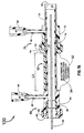
- FIG. 3 is a longitudinal cross-section of a proximal portion of the integrated catheter 10 and also shows the guide wire 30 and the yoke 80.
- the inner tube 11 has a central lumen 12 that extends through a female Luer fitting 50 located at the proximal end of the inner tube 11.
- the guide wire 30 is adapted to move slidably through the entire length of the lumen 12, thus making the catheter 10 an "over-the-wire” design.
- "Over-the-wire” designs have great advantages over "fixed wire” designs, or designs such as taught by Pinchuk (U.S. Patent #5,019,090) in which there is no guide wire taught at all because "over-the-wire” designs provide greatly improved trackability when advancing the catheters through tortuous coronary arteries.
- FIG. 3 also shows the outer tube 13 having at its proximal end an enlarged diameter section 46 which has a distal end surface 49.
- the section 46 has a side arm 53 with a lumen 54 and a female Luer fitting 52.
- the lumen 54 is in fluid communication with the annular passageway 26.
- a source of pressurized fluid such as a hypodermic syringe when attached to the female Luer fitting 52 can be used to inflate and deflate the balloon 16.
- the pusher tube 24 has at its proximal end a Tuohy-Borst fitting 60 which has a distal end surface 69.
- the Tuohy-Borst fitting 60 has a threaded main body 62, a nut 64 having a proximal end surface 68 and an elastomer gland 66. When the nut 64 is tightened down, the gland 66 makes a fluidic seal between the pusher tube 24 and the outer tube 13. When the nut 64 is loosened, the pusher tube 24 can move slidably over the outer tube 13.
- the Tuohy-Borst fitting 60 also has a side arm 55 with female Luer fitting 56 and a central lumen 57; which lumen 57 is in fluid communication with the annular passageway 27 that lies between the pusher tube 24 and the outer tube 13.
- the Tuohy-Borst fitting 70 situated at the proximal end of the outer sheath 20 has a main threaded body 72, a nut 74 having a proximal end surface 78 and an elastomer gland 76.
- the gland 76 makes a fluidic seal against and frictional attachment to the pusher tube 24.
- the outer sheath 20 is free to move slidably along the pusher tube 24.
- the Tuohy-Borst fitting 70 also includes a side arm 59 having a female Luer fitting 58 and a central lumen 67 that is in fluid communication with the annular passageway 28 that lies between the outer sheath 20 and the pusher tube 24.
- the material(s) selected for the tubes 11, 13, 20 and 24 can be Teflon® or an elastomer, such as polyurethane or polyethylene.
- the Tuohy-Borst fittings are typically fabricated from a harder plastic such as PVC or nylon, or a higher durometer of the same elastomer used for the outer sheath 20 or pusher tube 24.
- the outer surface of the pusher tube 24 and the inner surface of the outer sheath 20 should be treated to form a hydrophilic lubricous coating to reduce friction when the outer sheath is pulled back to release the stent 40.
- the stent should be coated with a covalently bonded heparin coating, as is well-known in the art of biomedical surfaces, to reduce thrombotic complications after stent placement.
- the stent could also have a hydrophilic lubricous coating on at least its exterior surface to reduce frictional forces when the outer sheath is pulled back to release the stent. That is, the stent would optimally have a heparin coating that was also hydrophilic and lubricous.
- the length of the integrated catheter 10 is typically 20 to 150 cm, depending on the vessel into which it is to be placed.
- the outer sheath 20 and pusher tube 24 are typically considerably shorter than the length of outer tube 13.
- the distal end of the outer sheath should be situated at least 3 cm distal to the proximal end of the balloon 16 and typically 10 cm back.
- the distal portion of the integrated catheter 10 can be advanced through an extended length of narrow stenosis and through tortuously curved arteries without the encumbrance and added stiffness of the pusher tube 24, outer sheath 20 and stent 40 which could limit the catheter's trackability over a guide wire.
- the outer sheath 20 and pusher tube 24 can be advanced together until the distal end of the outer sheath 20 is located at the proximal end of the balloon 16.
- the diameter of the catheter will typically vary from 1.0 to 10.0 mm depending on its use.
- the radiopaque marker bands 17, 21 and 25 are typically made from a dense metal such as an alloy of tantalum, platinum or gold.
- the yoke 80 is typically made from a fairly rigid plastic, such as PVC.
- FIG. 1 defines the length L1 measured from the distal end of the outer sheath 20 to the proximal end of the balloon 16.
- L1 could be 0, this would place the sheath 20, pusher tube 24 and stent 40 sufficiently close to the distal end of the integrated catheter 10 that it could prevent the easy advancement of the system through the tortuous curvature of coronary arteries. If, however, L1 was initially set at a length of at least 0.5 cm and preferably 3 to 20 cm, then the additional stiffness caused by the lack of flexibility of the outer sheath 20, pusher tube 24 and stent 40 would not prevent the balloon 16 from being advanced over the guide wire 30 and into an arterial stenosis.
- L1 might be initially set at, let us say, 5cm, if placing of the distal portion of the integrated catheter 10 into coronary vasculature was made difficult because of the stiffness of the outer sheath 20, outer tube 24, and stent 40, then the Tuohy-Borst fitting 60 (FIG. 3) could be loosened and the length L2 reduced, thus increasing the length L1.
- a method for using the "over-the-wire" design, integrated catheter 10 for the treatment of an obstructed coronary artery would be as follows:
- a single integrated catheter 10 can be used for initial dilatation of a blockage in a vessel, for release of a stent within that vessel at the site where the dilatation occurred, and the balloon can be then reinflated to allow a shape memory metal stent or a balloon expandable stent to expand to a final, fully expanded state.
- the requirement for one or more separate balloon dilatation catheters and a separate stent delivery catheter has been eliminated with a resulting cost economy and a decrease in the time required to perform this procedure.
- a displacement limiting means located outside the patient's body must be utilized.
- One such displacement limiting means is the yoke 80 that is shown in FIGS. 3, 6A and 6B.
- the yoke 80 has a main longitudinal section 81, a proximal end piece 82 having a hole 84 and a slit 86, and a distal end piece 83 having a hole 85.
- the yoke 80 is assembled onto the integrated catheter 10 by first sliding the hole 85 over the pusher tube 24 before the Tuohy-Borst fitting 70 and outer sheath 20 are slid over the pusher tube 24. Then the slit 86 is pushed over the proximal end of the inner tube 11, as is shown in FIG. 3.
- a pusher tube longitudinal displacement limiting means assures that the stent 40 will not be positioned to a more distal position relative to the balloon 16 than that position shown in FIG. 4F.
- FIG. 7A illustrates a sheath assembly 100 that consists of the outer sheath 20, pusher tube 24, Tuohy-Borst fitting 60, Tuohy-Borst fitting 70, and spacer 90, which assembly 100 can be advanced over the guide wire 30 without using a balloon angioplasty catheter.
- the sheath assembly 100 could be used as a separate means for inserting a stent if prior balloon dilation was not required or to act as a guide for the introduction or exchange of balloon dilation catheters.
- FIGS. 7A, 7B, 8A, and 8B show the spacer 90 having a pull tab 92, warning label 94, cylindrical portion 96, and slit 98.
- the slit 98 allows the elastomer material of the spacer 90 to be deformed so that it can be placed onto or pulled off from the pusher tube 24.
- the length L4 of the spacer 90 is typically equal to the length of the stent 40, plus the length of the conical distal portion 22 of the outer sheath 20, plus approximately 0.5 cm. The length L4 is set so that when the spacer 90 is removed, the outer sheath 20 can be pulled back relative to the pusher tube so that the stent 40 can be released.
- FIG. 7B illustrates how the sheath assembly 100 can be placed over a typical balloon angioplasty catheter (as previously shown in FIGS. 1, 2, 3 and 4A to 4J). The only difference being that the spacer 90 is used and not the yoke 80. It is also possible to utilize a combination of yoke 80 and spacer 90 or other equivalent means to prevent the inadvertent release of the stent.
- the invention described herein can be used with a variety of angioplasty balloon catheters including those with fixed guide wires at their distal end, i.e., "fixed wire” catheters.
- the sheath assembly 100 shown in FIG. 7A could be used with a large variety of balloon angioplasty catheters as selected by the physician at the time of the vessel opening procedure.
- radiopaque marker bands could be used with any integrated design.
Abstract
Description
- This invention is generally in the field of devices for opening and maintaining patency within vessels of the human body, for example for percutaneous transluminal coronary angioplasty (PTCA) and stent delivery into a dilated arterial stenosis.
- It is well known to use balloon angioplasty catheters for the dilation of various vessels of the human body and most particularly for opening stenotic arteries. It is also well-known to place stents into vessels to maintain patency of that vessel. It is also well-known to use a balloon catheter for embedding a stent into the wall of the vessel to prevent stent migration.
- It is typical to use separate catheters for vessel dilation and for stent delivery. This requires one or more catheter exchanges which increase the time and cost for performing interventional procedures. Since the patient is typically in some discomfort during such procedures, it is also highly advantageous to the patient to make the interventional procedure as short as possible. Furthermore, removing a balloon angioplasty catheter after balloon dilation can result in an intimal dissection that can preclude stent placement.
- In U.S. Patent #5,019,090, L. Pinchuk illustrates in FIGS. 13 to 18 a method for mounting a self-deploying stent on a balloon angioplasty catheter. However, Pinchuk's method functions only for self-deploying stents and not balloon expandable stents, and furthermore, his method requires the balloon to be advanced at least 3 cm beyond the distal end of the stenosis that is treated. That is not possible in many coronary arteries because of restrictions within the lumens of the coronary arteries. Furthermore, Pinchuk's method requires two additional steps, i.e., one is a further advancement of the balloon after balloon angioplasty is performed, and later pulling the balloon back within the deployed stent. Pulling back of the balloon catheter can cause the stent to be moved away from its optimal location. Additional steps in such a procedure require additional time which is generally undesirable. Furthermore, Pinchuk does not teach a means or method for the use of a guide wire through the center of the integrated catheter so as to guide it through the typically tortuous coronary vasculature. Still further, Pinchuk teaches an outer sheath with a blunt end whose operability can be defeated because of intimal dissection which often occurs as a result of balloon angioplasty.
- An example of a prior art device is that taught by Harrison M. Lazarus in International Patent Application publication number WO 89/08433. That document discloses an integrated catheter system comprising a balloon angioplasty catheter, a cylindrical tube which forms an outer sheath over a graft for inserting into a blood vessel. The tube has a graft containing hollow for containing a radially expanding graft and means for pulling back the tube from over the graft arranged to be located outside the human body. The tube also has a distal end portion having a frustoconical shape. Pusher means are affixed to the catheter.
- The present invention overcomes the disadvantages of the prior art devices by integrating a balloon catheter and a stent delivery catheter into a single device which can perform both balloon angioplasty and stent delivery. Although this invention could be used for any vessel of the human body including but not limited to arteries, vein, vascular grafts, biliary ducts, urethras, fallopian tubes, bronchial tubes, etc., the description herein will highlight the use of this device for arterial balloon angioplasty (and specifically PRCA) followed by intra-arterial stenting.
- In accordance with the invention, there is provided an integrated catheter system for performing a dilation procedure within a vessel of a human body and for placement of a stent within that region of the vessel that underwent dilation, the catheter system comprising:
- a balloon angioplasty catheter having a balloon located near the catheter's distal end, the balloon having a proximal end fixedly attached to an elongated tube, the balloon being able to be inflated to an inflated state and deflated to a deflated state;
- a first elongate cylindrical tube which is a pusher tube having a proximal end and a distal end and being adapted to move slidably over the balloon angioplasty catheter;
- a second elongate cylindrical tube which is an outer sheath, the pusher tube being adapted to move slidably within the outer sheath which has a stent containment cavity for containing a radially expandable stent situated near the sheath's distal end, the stent containment cavity being bounded at its distal end by a distal portion having a frustoconical shape, the frustoconical distal portion having a distal end that intersects the tube of the balloon angioplasty catheter at an acute angle, the stent containment cavity being bounded at its proximal end by the distal end of the pusher tube, the outer sheath and the pusher tube each having separate proximal pullback means adapted to lie outside the human body for pulling the outer sheath back relative to the pusher tube so as to release a radially expandable stent from the stent containment cavity so that the stent can be expanded radially outward against the vessel wall.
-
- Thus, this invention enables vessel dilation, stent placement, and balloon enhanced embedding of the stent into the vessel wall, all with a single integrated catheter.
- This invention can permit the balloon the remain in one place in the artery during (1) balloon angioplasty, (2) stent placement, and finally (3) the further embedding of the stent into the arterial wall.
- With an embodiment of this invention, a self-expanding stent can be deployed by pulling back a slidable outer sheath which allows the stent to expand radially outward.
- Thus the invention can provide an improved apparatus for deploying balloon expandable stents.
- An embodiment of this invention can provide an integrated catheter capable of being advanced over a flexible guide wire.
- The provision of a conically shaped distal portion of the outer sheath enables proper placement of the stent even in cases of severe intimal dissection which could cause an intimal flap that could block the passage of an outer sheath having a blunt end.
- Initially placing the stent at least several centimeters proximal to the proximal end of the angioplasty balloon allows better tackability of the catheter's distal end over a flexible guide wire and through tortuous coronary arteries and through a long tight stenosis.
- Means are preferably provided to limit the forward displacement of the integrated catheter's pusher tube to prevent the stent from being pushed beyond the distal end of the balloon.
- The integrated catheter system of this invention can be provided by a separate outer sheath, stent and pusher tube assembly placed over a guide wire or over any balloon angioplasty catheter in the catheterization laboratory prior to placement of the entire assembly into a vessel of human body.
- Preferably removable means maintains a set spacing between the pusher tube and the outer sheath to preclude the inadvertent and premature release of the stent.
- This invention preferably allows the introduction or exchange of balloon angioplasty catheters through a stent delivery catheter already placed in the body or just before placement in the body.
- These and other objects and advantages of this invention will become apparent to a person of ordinary skill in this art upon careful reading of the detailed description of this invention including the Drawings and Claims presented herein.
- Embodiments of the invention are described hereinafter, by way of example only, in combination with the accompanying drawings, in which:
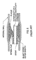
- FIG. 1 is a longitudinal cross-section of a distal portion of the integrated, dual-function catheter system;
- FIG. 2 is a transverse cross-section of the catheter at Section 2-2 of FIG. 1;
- FIG. 3 is a longitudinal cross-section of a proximal portion of the integrated, dual-function catheter system illustrating means for guide wire and fluid access to various portions of the catheter system;
- FIG. 4A is a longitudinal cross-section of a distal portion of the integrated catheter system showing various portions of the balloon and the stent and showing an unexpanded balloon placed with an arterial stenosis;
- FIG. 4B shows the balloon in its deployed (expanded) state;
- FIG. 4C shows the outer sheath, stent and pusher tube advanced in a distal direction until the distal end of the outer sheath is adjacent to the proximal end of the balloon;
- FIG. 4D shows the balloon deflated;
- FIG. 4E shows the distal end of the sheath assembly being advanced over the deflated balloon;
- FIG. 4F shows the sheath assembly in its most forward position relative to the balloon;
- FIG. 4G shows the outer sheath pulled back, thus releasing the self-expanding stent so that it deploys outward against the vessel wall;
- FIG. 4H shows the balloon as it is expanded to place a balloon expandable stent into the arterial wall or to further embed a self-expanding stent into the arterial wall;
- FIG. 4I shows the stent in place with the catheter system being removed from the artery;
- FIG. 4J shows a balloon expandable stent as it is placed onto the deflated balloon;
- FIG. 5 illustrates how a prior art blunt tipped outer sheath of an integrated stent and balloon angioplasty catheter can be made dysfunctional because of an intimal flap formed in the plaque after balloon dilation;
- FIG. 6A is a side view of a yoke used to prevent excessive longitudinal displacement of the pusher tube;
- FIG. 6B is an end view of the yoke;
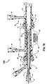
- FIG. 7A is a longitudinal cross-section of an alternative embodiment of a sheath assembly (including a removable spacer) as placed over a guide wire;
- FIG. 7B is a longitudinal cross-section of an alternative embodiment of the sheath assembly placed over a balloon angioplasty catheter and a guide wire;
- FIG. 8A is a side view of a removable spacer used to prevent inadvertent release of the stent; and,
- FIG. 8B is a cross-section at
Section 8B-8B of FIG. 8A showing a transverse cross-section of the spacer. -
- The same inventors have described various means for delivering self-expanding, shape memory metal stents into a vessel of the human body. The invention described herein expands the concepts taught in those prior applications by teaching a dual-function integrated catheter system that has an expandable balloon located near the catheter's distal end whose purposes are to initially dilate a vessel and then, after a stent is deployed, to further embed that stent into the wall of the vessel. The balloon can also be used to deploy a stent if the stent is not self-expandable. The present design is capable of performing these functions while retaining the balloon at one single longitudinal position within the artery, i.e., at no time is there a need to advance the balloon beyond the stenotic lesion.
- FIGS. 1, 2 and 3 illustrate an integrated dual-function catheter system consisting of an
integrated catheter 10, aguide wire 30, and astent 40. Theintegrated catheter 10 includes a slidableouter sheath 20, anouter tube 13, aninner tube 11, apusher tube 24, anexpandable balloon 16, two Tuohy-Borst fittings female Luer fittings yoke 80. Thecatheter 10 is capable of being advanced over theguide wire 30. - FIG. 1 shows that the
inner tube 11 has adistal portion 11A that extends for a considerable distance beyond the distal end of theballoon 16. Also, thedistal portion 11A has adistal end 11B that has a conical taper. Because of the conical shape of thedistal end 11B and because thedistal portion 11A of theinner tube 11 is highly flexible, theintegrated catheter 10 can readily track over a highlyflexible guide wire 30. The distal end of theballoon 19 is adhesively joined to the proximal end of thedistal portion 11A of theinner tube 11. The proximal end of theballoon 16 is adhesively joined to the distal end of theouter tube 13. Theannular passageway 26 that lies between the outer surface of theinner tube 11 and the inner surface of theouter tube 13 is in fluid communication with theinterior chamber 19 of theballoon 16. Aradiopaque marker band 17 mounted on theinner tube 11 indicates the longitudinal center of theballoon 16. Theguide wire 30 passes through thecentral lumen 12 of theinner tube 11. - The
outer sheath 20 has a conically shaped,distal portion 22 that (as seen in FIG. 2) has fourslits 23 that extend in a longitudinal direction. Although FIG. 2 shows four slits, any number of slits from one to sixteen could be used. The purpose of theslits 23 is to allow the outer sheath to be easily pulled back over thestent 40 andpusher tube 24. Within a distal portion of theouter sheath 20 is astent 40 that lies within astent containment cavity 42. Thestent containment cavity 42 is bounded by the interior surfaces of theouter sheath 20 including itsdistal portion 22, the outer surface of theouter tube 13, and the distal surface of theradiopaque marker band 25 that is fixedly joined to the distal end of thepusher tube 24. Aradiopaque marker band 21 is also fixedly attached to theouter sheath 20 as shown in FIG. 1. Theannular passageway 27 lies between the inner surface of thepusher tube 24 and the outer surface of theouter tube 13. Theannular passageway 28 lies between the inner surface of theouter sheath 20 and the outer surface of thepusher tube 24. - FIG. 3 is a longitudinal cross-section of a proximal portion of the
integrated catheter 10 and also shows theguide wire 30 and theyoke 80. Theinner tube 11 has acentral lumen 12 that extends through a female Luer fitting 50 located at the proximal end of theinner tube 11. Theguide wire 30 is adapted to move slidably through the entire length of thelumen 12, thus making thecatheter 10 an "over-the-wire" design. "Over-the-wire" designs have great advantages over "fixed wire" designs, or designs such as taught by Pinchuk (U.S. Patent #5,019,090) in which there is no guide wire taught at all because "over-the-wire" designs provide greatly improved trackability when advancing the catheters through tortuous coronary arteries. - FIG. 3 also shows the
outer tube 13 having at its proximal end anenlarged diameter section 46 which has adistal end surface 49. Thesection 46 has aside arm 53 with a lumen 54 and a female Luer fitting 52. The lumen 54 is in fluid communication with theannular passageway 26. A source of pressurized fluid such as a hypodermic syringe when attached to the female Luer fitting 52 can be used to inflate and deflate theballoon 16. - The
pusher tube 24 has at its proximal end a Tuohy-Borst fitting 60 which has adistal end surface 69. The Tuohy-Borst fitting 60 has a threadedmain body 62, anut 64 having aproximal end surface 68 and anelastomer gland 66. When thenut 64 is tightened down, thegland 66 makes a fluidic seal between thepusher tube 24 and theouter tube 13. When thenut 64 is loosened, thepusher tube 24 can move slidably over theouter tube 13. The Tuohy-Borst fitting 60 also has aside arm 55 with female Luer fitting 56 and acentral lumen 57; which lumen 57 is in fluid communication with theannular passageway 27 that lies between thepusher tube 24 and theouter tube 13. - The Tuohy-
Borst fitting 70 situated at the proximal end of theouter sheath 20 has a main threadedbody 72, anut 74 having aproximal end surface 78 and anelastomer gland 76. When the nut 4 is tightened down, thegland 76 makes a fluidic seal against and frictional attachment to thepusher tube 24. When thenut 74 is loosened, theouter sheath 20 is free to move slidably along thepusher tube 24. The Tuohy-Borst fitting 70 also includes aside arm 59 having a female Luer fitting 58 and acentral lumen 67 that is in fluid communication with theannular passageway 28 that lies between theouter sheath 20 and thepusher tube 24. - The material(s) selected for the
tubes outer sheath 20 orpusher tube 24. The outer surface of thepusher tube 24 and the inner surface of theouter sheath 20 should be treated to form a hydrophilic lubricous coating to reduce friction when the outer sheath is pulled back to release thestent 40. The stent should be coated with a covalently bonded heparin coating, as is well-known in the art of biomedical surfaces, to reduce thrombotic complications after stent placement. The stent could also have a hydrophilic lubricous coating on at least its exterior surface to reduce frictional forces when the outer sheath is pulled back to release the stent. That is, the stent would optimally have a heparin coating that was also hydrophilic and lubricous. - The length of the
integrated catheter 10 is typically 20 to 150 cm, depending on the vessel into which it is to be placed. Theouter sheath 20 andpusher tube 24 are typically considerably shorter than the length ofouter tube 13. When theouter sheath 20 andpusher tube 24 are pulled back to their most proximal position, the distal end of the outer sheath should be situated at least 3 cm distal to the proximal end of theballoon 16 and typically 10 cm back. When the distal end of theouter sheath 20 is approximately 10 cm back from the proximal end of theballoon 16, the distal portion of theintegrated catheter 10 can be advanced through an extended length of narrow stenosis and through tortuously curved arteries without the encumbrance and added stiffness of thepusher tube 24,outer sheath 20 andstent 40 which could limit the catheter's trackability over a guide wire. Once theballoon 16 is placed within a stenosis, and preferably when the balloon is inflated, theouter sheath 20 andpusher tube 24 can be advanced together until the distal end of theouter sheath 20 is located at the proximal end of theballoon 16. The diameter of the catheter will typically vary from 1.0 to 10.0 mm depending on its use. Theradiopaque marker bands yoke 80 is typically made from a fairly rigid plastic, such as PVC. - FIG. 1 defines the length L1 measured from the distal end of the
outer sheath 20 to the proximal end of theballoon 16. Although L1 could be 0, this would place thesheath 20,pusher tube 24 andstent 40 sufficiently close to the distal end of theintegrated catheter 10 that it could prevent the easy advancement of the system through the tortuous curvature of coronary arteries. If, however, L1 was initially set at a length of at least 0.5 cm and preferably 3 to 20 cm, then the additional stiffness caused by the lack of flexibility of theouter sheath 20,pusher tube 24 andstent 40 would not prevent theballoon 16 from being advanced over theguide wire 30 and into an arterial stenosis. Although L1 might be initially set at, let us say, 5cm, if placing of the distal portion of theintegrated catheter 10 into coronary vasculature was made difficult because of the stiffness of theouter sheath 20,outer tube 24, andstent 40, then the Tuohy-Borst fitting 60 (FIG. 3) could be loosened and the length L2 reduced, thus increasing the length L1. - A method for using the "over-the-wire" design,
integrated catheter 10 for the treatment of an obstructed coronary artery would be as follows: - 1. By conventional means, an introducer sheath and a coronary guiding catheter are inserted at the groin and the guiding catheter's distal end is advanced until it is situated within the ostium of a coronary artery.
- 2. Saline solution is flushed through each of the
three
annular passageways central lumen 12 of thecatheter 10 by means of the fourfemale Luer fittings - 3. A
guide wire 30 that has been pre-loaded into theintegrated catheter 10 is advanced with thecatheter 10 through the guiding catheter, and theguide wire 30 is then advanced through a coronary artery blockage. - 4. The
catheter 10 is further advanced over theguide wire 30 until thedistal end portion 11A of theinner tube 11 lies just distal to the blockage as shown in FIG. 4A. This is accomplished with thepusher tube 24 and theouter sheath 20 in their most proximal positions which occurs with a typical length L3 (as shown in FIG. 3) that is equal to L1 plus the length of the stent, plus the length of the conicaldistal portion 22, plus approximately 0.5 cm. The length L3 is set so as to prevent the stent from being displaced beyond the distal end of theballoon 16. The nuts 64 and 74 of the Tuohy-Borst fittings outer sheath 20 to thepusher tube 24 and thepusher tube 24 to theouter tube 13. - 5. A fluid pressurization means is then joined to
the Luer fitting 52 and the
balloon 16 is inflated (as shown in FIG. 4B) to an outside diameter between 2.0 and 5.0 mm, depending on the nominal size of the coronary artery in which the blockage occurred. - 6. While the balloon is inflated, the
nut 64 of the Tuohy-Borst fitting 60 is loosened and thepusher tube 24 and outer sheath 20 (which are frictionally joined together by the Tuohy-Borst fitting 70) are advanced forward together in a distal direction, thus decreasing the length L3 until the distal end of the conically shapeddistal portion 22 of theouter sheath 11 is in contact with the proximal end of theballoon 16; i.e., L1 = 0. This configuration is shown in FIG. 4C. - 7. The balloon is then deflated as shown in FIG. 4D.
- 8. The
pusher tube 24 andouter sheath 20 are then advanced together over the deflated balloon a shown in FIG. 4E, further reducing the length L3. It is important to note that any intimal dissection resulting in an intimal flap will be lifted away from the surface of the deflatedballoon 16 by the pointed distal end of the conicaldistal end portion 22 of theouter sheath 20. This is in contradistinction to all prior art integrated catheter devices which have outer sheaths whose ends are blunt and therefore could not have their forward motion stopped by an intimal flap that was in contact with the outer surface of either the balloon or the outer shaft of a balloon angioplasty catheter. This disadvantage of the prior art that can prevent proper functioning of an integrated catheter is shown in FIG. 5. - 9. FIG. 4F shows that the
outer sheath 20 andpusher tube 24 have been advanced until thestent 40 lies over the deflatedballoon 16. Theyoke 80 is dimensioned to prevent thepusher tube 24 from being extended beyond the point shown in FIG. 4F, thus eliminating the possibility that the stent would be deployed at a point beyond thedistal end 11B of theinner tube 11. - 10. FIG. 4G illustrates that a self-expanding,
shape memory metal (such as Nitinol®) stent would expand
radially outward to engage the interior surface of the
dilated stenosis when the
outer sheath 20 is pulled back. Before theouter sheath 20 is pulled back, thenut 64 of the Tuohy-Borst fitting 60 is tightened down to frictionally join thepusher tube 24 to theouter tube 13, and thenut 74 is loosened so that theouter sheath 20 can be pulled backward in a proximal direction until thestent 40 is released. - 11. FIG. 4J illustrates that a balloon expandable
stent (as opposed to a self-expanding stent) would remain in
contact with the outer surface of the deflated
balloon 16 after theouter sheath 20 is pulled back. A slight inflation of theballoon 16 before thesheath 20 is pulled back may be necessary to hold thestent 40 during the pulling back of thesheath 20. - 12. FIG. 4H shows how either the self-expanding or
balloon expandable stent would look after the
balloon 16 is expanded radially outward. In the case of the self-expanding stent, the purpose of the balloon expansion is to push back the plaque to allow a comparatively fragile, shape memory metal stent to reach its final, fully expanded shape. Until that final shape is achieved, shape memory metal stents do not exert a sufficiently strong outward radial force to outwardly deform hard plaque. However, once the fully expanded shape of the stent is achieved with the assistance of theballoon 16, shape memory metal stents are sufficiently strong to maintain a considerable outward force on the dilated plaque. At no time does the expanded balloon deform a shape memory metal by exceeding the elastic limit of the metal of the stent. On the other hand, the balloon expandable stent shown in FIG. 4J is severely deformed by the expandingballoon 16, thus exceeding the elastic limit of the metal of the stent. This creates a plastic deformation of the stent so that it will retain its expanded shape as shown in FIG. 4I. - 13. The
balloon 16 is then deflated (as shown in FIG. 4I) and thecatheter 10 and theguide wire 30 are removed from the artery. - 14. The guiding catheter and introducer sheath are then removed using appropriate methods that are well-known in interventional cardiology.
-
- As described in steps 1 through 14 above, a single
integrated catheter 10 can be used for initial dilatation of a blockage in a vessel, for release of a stent within that vessel at the site where the dilatation occurred, and the balloon can be then reinflated to allow a shape memory metal stent or a balloon expandable stent to expand to a final, fully expanded state. Thus, the requirement for one or more separate balloon dilatation catheters and a separate stent delivery catheter has been eliminated with a resulting cost economy and a decrease in the time required to perform this procedure. - It would be highly disadvantageous if it were possible to advance the
stent 40 beyond the distal end of theinner tube 11. If that occurred, the stent could be set free at an incorrect location within the artery. To disallow that possibility, a displacement limiting means located outside the patient's body must be utilized. One such displacement limiting means is theyoke 80 that is shown in FIGS. 3, 6A and 6B. Theyoke 80 has a mainlongitudinal section 81, aproximal end piece 82 having ahole 84 and aslit 86, and adistal end piece 83 having ahole 85. Theyoke 80 is assembled onto theintegrated catheter 10 by first sliding thehole 85 over thepusher tube 24 before the Tuohy-Borst fitting 70 andouter sheath 20 are slid over thepusher tube 24. Then theslit 86 is pushed over the proximal end of theinner tube 11, as is shown in FIG. 3. A pusher tube longitudinal displacement limiting means assures that thestent 40 will not be positioned to a more distal position relative to theballoon 16 than that position shown in FIG. 4F. - FIG. 7A illustrates a
sheath assembly 100 that consists of theouter sheath 20,pusher tube 24, Tuohy-Borst fitting 60, Tuohy-Borst fitting 70, andspacer 90, whichassembly 100 can be advanced over theguide wire 30 without using a balloon angioplasty catheter. Thus, thesheath assembly 100 could be used as a separate means for inserting a stent if prior balloon dilation was not required or to act as a guide for the introduction or exchange of balloon dilation catheters. A unique feature shown in FIG. 7A is aremovable spacer 90 that is used to prevent inadvertent release of the stent by disallowing thepusher tube 24 from being advanced in a forward direction relative to theouter sheath 20 until thespacer 90 is removed. FIGS. 7A, 7B, 8A, and 8B show thespacer 90 having apull tab 92, warninglabel 94,cylindrical portion 96, and slit 98. Theslit 98 allows the elastomer material of thespacer 90 to be deformed so that it can be placed onto or pulled off from thepusher tube 24. The length L4 of thespacer 90 is typically equal to the length of thestent 40, plus the length of the conicaldistal portion 22 of theouter sheath 20, plus approximately 0.5 cm. The length L4 is set so that when thespacer 90 is removed, theouter sheath 20 can be pulled back relative to the pusher tube so that thestent 40 can be released. - FIG. 7B illustrates how the
sheath assembly 100 can be placed over a typical balloon angioplasty catheter (as previously shown in FIGS. 1, 2, 3 and 4A to 4J). The only difference being that thespacer 90 is used and not theyoke 80. It is also possible to utilize a combination ofyoke 80 andspacer 90 or other equivalent means to prevent the inadvertent release of the stent. - It should also be understood that the invention described herein can be used with a variety of angioplasty balloon catheters including those with fixed guide wires at their distal end, i.e., "fixed wire" catheters. In fact, the
sheath assembly 100 shown in FIG. 7A could be used with a large variety of balloon angioplasty catheters as selected by the physician at the time of the vessel opening procedure. - It should be further understood that one, two, or more radiopaque marker bands could be used with any integrated design.
- Although specific embodiments have been described, it will be appreciated that various other modifications, adaptions, and alternative designs are of course possible within the scope of the invention claimed herein.
Claims (17)
- An integrated catheter system for performing a dilation procedure within a vessel of a human body and for placement of a stent within that region of the vessel that underwent dilation, the catheter system comprising:a balloon angioplasty catheter having a balloon (16) located near the catheter's distal end (11A), the balloon (16) having a proximal end fixedly attached to an elongated tube (13), the balloon (16) being able to be inflated to an inflated state and deflated to a deflated state;a first elongate cylindrical tube which is a pusher tube (24) having a proximal end and a distal end and being adapted to move slidably over the balloon angioplasty catheter;a second elongate cylindrical tube which is an outer sheath (20), the pusher tube (24) being adapted to move slidably within the outer sheath (20) which has a stent containment cavity (42) for containing a radially expandable stent (40) situated near the sheath's distal end, the stent containment cavity (42) being bounded at its distal end by a distal portion (22) having a frustoconical shape, the frustoconical distal portion (22) having a distal end that intersects the tube (13) of the balloon angioplasty catheter at an acute angle, the stent containment cavity (42) being bounded at its proximal end by the distal end of the pusher tube (24), the outer sheath (20) and the pusher tube (24) each having separate proximal pullback means (70, 60) adapted to lie outside the human body for pulling the outer sheath (20) back relative to the pusher tube (24) so as to release a radially expandable stent (40) from the stent containment cavity (42) so that the stent (40) can be expanded radially outward against the vessel wall.
- An integrated catheter system according to Claim 1 wherein the system is suited for performing a dilation procedure within the coronary arteries of a human body and wherein the distal end of the outer sheath (20) is arranged to be locatable to a distance of more than 0.5 cm back from the proximal end of the balloon (16) as the balloon (16) is being advanced within the vessel of the human body.
- The catheter system of Claim 1 or Claim 2, wherein the balloon angioplasty catheter is of the "over-the-wire" design having a central lumen (12) extending throughout the entire length of the balloon angioplasty catheter.
- The catheter system of Claim 3, further comprising a flexible guide wire (30) adapted to be advanced through the central lumen (12) of the balloon angioplasty catheter.
- The catheter system of any preceding claim, wherein the distal end portion of the frustoconical distal portion (22) of the outer sheath (20) is adapted to be moved with a snug fit over the balloon (16) when the balloon (16) is in its deflated state.
- The catheter system of Claim 5, wherein the frustoconical distal portion (22) of the outer sheath (20) includes at least one longitudinally placed slit to allow the outer sheath (20) to be easily pulled back over the stent (40) and over the pusher tube (24).
- The catheter system of any preceding Claim, wherein the pusher tube (24) includes a radiopaque marker band (25) at its distal end.
- The catheter system of any preceding Claim, wherein the radially expandable stent (40) is a balloon expandable stent.
- The catheter system of any of Claims 1 to 7 , wherein the radially expandable stent (40) is a self-expanding stent.
- The catheter system of Claim 9, wherein the self-expanding stent is made from a shape memory alloy metal.
- The catheter system of any preceding Claim, wherein the proximal pullback means (60, 70) is a Tuohy-Borst fitting.
- The catheter system of any preceding Claim, wherein the integrated catheter has four separate lumens (12, 26, 27, 28), each being accessible for flushing from the catheter's proximal end.
- The catheter system of Claim 12, wherein three of the lumens (26, 27, 28) are annular passageways and the central lumen (12) is generally of a cylindrical geometry.
- The catheter system of any preceding Claim, wherein at least one radiopaque marker band (21, 25) is used to indicate the location of the stent containment cavity (42).
- The catheter system of any preceding Claim, further comprising a longitudinal displacement limiting means (80) to prevent the inadvertent release of the stent (40) beyond the distal end of the inflatable balloon (16).
- The catheter system of any preceding Claim, further comprising a longitudinal displacement limiting means (90) to prevent the inadvertent release of the stent (40) by disallowing inadvertent pullback of the outer sheath (20) relative to the pusher tube (24).
- The catheter system of Claim 16, wherein the longitudinal displacement limiting means (90) is a removable spacer (90).
Applications Claiming Priority (2)
| Application Number | Priority Date | Filing Date | Title |
|---|---|---|---|
| US35149894A | 1994-12-07 | 1994-12-07 | |
| US351498 | 1994-12-07 |
Publications (2)
| Publication Number | Publication Date |
|---|---|
| EP0720837A1 EP0720837A1 (en) | 1996-07-10 |
| EP0720837B1 true EP0720837B1 (en) | 2003-06-25 |
Family
ID=23381176
Family Applications (1)
| Application Number | Title | Priority Date | Filing Date |
|---|---|---|---|
| EP95308773A Expired - Lifetime EP0720837B1 (en) | 1994-12-07 | 1995-12-05 | Integrated dual-function catheter system for balloon angioplasty and stent delivery |
Country Status (7)
| Country | Link |
|---|---|
| US (1) | US5634928A (en) |
| EP (1) | EP0720837B1 (en) |
| JP (1) | JPH08243170A (en) |
| AT (1) | ATE243478T1 (en) |
| CA (1) | CA2163708C (en) |
| DE (1) | DE69531143T2 (en) |
| ES (1) | ES2201089T3 (en) |
Families Citing this family (167)
| Publication number | Priority date | Publication date | Assignee | Title |
|---|---|---|---|---|
| US5498227A (en) | 1993-09-15 | 1996-03-12 | Mawad; Michel E. | Retrievable, shielded radiotherapy implant |
| DE69514690T3 (en) * | 1994-02-25 | 2006-09-14 | Fischell, Robert E. | stent |
| US5814062A (en) * | 1994-12-22 | 1998-09-29 | Target Therapeutics, Inc. | Implant delivery assembly with expandable coupling/decoupling mechanism |
| US6602281B1 (en) * | 1995-06-05 | 2003-08-05 | Avantec Vascular Corporation | Radially expansible vessel scaffold having beams and expansion joints |
| US6077295A (en) | 1996-07-15 | 2000-06-20 | Advanced Cardiovascular Systems, Inc. | Self-expanding stent delivery system |
| US5911752A (en) * | 1996-09-13 | 1999-06-15 | Intratherapeutics, Inc. | Method for collapsing a stent |
| US5843090A (en) * | 1996-11-05 | 1998-12-01 | Schneider (Usa) Inc. | Stent delivery device |
| US6071286A (en) * | 1997-02-19 | 2000-06-06 | Mawad; Michel E. | Combination angioplasty balloon/stent deployment device |
| US6015420A (en) * | 1997-03-06 | 2000-01-18 | Scimed Life Systems, Inc. | Atherectomy device for reducing damage to vessels and/or in-vivo stents |
| US5792144A (en) * | 1997-03-31 | 1998-08-11 | Cathco, Inc. | Stent delivery catheter system |
| US6143016A (en) * | 1997-04-21 | 2000-11-07 | Advanced Cardiovascular Systems, Inc. | Sheath and method of use for a stent delivery system |
| US5906619A (en) * | 1997-07-24 | 1999-05-25 | Medtronic, Inc. | Disposable delivery device for endoluminal prostheses |
| US6330884B1 (en) * | 1997-11-14 | 2001-12-18 | Transvascular, Inc. | Deformable scaffolding multicellular stent |
| US6533807B2 (en) | 1998-02-05 | 2003-03-18 | Medtronic, Inc. | Radially-expandable stent and delivery system |
| US6174327B1 (en) | 1998-02-27 | 2001-01-16 | Scimed Life Systems, Inc. | Stent deployment apparatus and method |
| US6210318B1 (en) | 1999-03-09 | 2001-04-03 | Abiomed, Inc. | Stented balloon pump system and method for using same |
| US6443980B1 (en) | 1999-03-22 | 2002-09-03 | Scimed Life Systems, Inc. | End sleeve coating for stent delivery |
| US6221097B1 (en) * | 1999-03-22 | 2001-04-24 | Scimed Life System, Inc. | Lubricated sleeve material for stent delivery |
| US6375676B1 (en) | 1999-05-17 | 2002-04-23 | Advanced Cardiovascular Systems, Inc. | Self-expanding stent with enhanced delivery precision and stent delivery system |
| US6168617B1 (en) * | 1999-06-14 | 2001-01-02 | Scimed Life Systems, Inc. | Stent delivery system |
| US6287291B1 (en) | 1999-11-09 | 2001-09-11 | Advanced Cardiovascular Systems, Inc. | Protective sheath for catheters |
| US6702802B1 (en) | 1999-11-10 | 2004-03-09 | Endovascular Technologies, Inc. | Catheters with improved transition |
| US7758624B2 (en) | 2000-11-13 | 2010-07-20 | C. R. Bard, Inc. | Implant delivery device |
| DE60035791T2 (en) * | 1999-11-11 | 2008-04-30 | Angiomed Gmbh & Co. Medizintechnik Kg | INTRODUCING DEVICE FOR AN IMPLANT |
| US6264671B1 (en) * | 1999-11-15 | 2001-07-24 | Advanced Cardiovascular Systems, Inc. | Stent delivery catheter and method of use |
| US6443979B1 (en) | 1999-12-20 | 2002-09-03 | Advanced Cardiovascular Systems, Inc. | Expandable stent delivery sheath and method of use |
| US6280465B1 (en) | 1999-12-30 | 2001-08-28 | Advanced Cardiovascular Systems, Inc. | Apparatus and method for delivering a self-expanding stent on a guide wire |
| FR2805750B1 (en) | 2000-03-02 | 2002-09-20 | Braun Celsa Sa | SHEATH FOR A MEDICAL INTRODUCER AND ITS MANUFACTURING METHOD |
| US6702843B1 (en) | 2000-04-12 | 2004-03-09 | Scimed Life Systems, Inc. | Stent delivery means with balloon retraction means |
| US6733520B2 (en) | 2000-09-22 | 2004-05-11 | Scimed Life Systems, Inc. | Sandwich striped sleeve for stent delivery |
| US6602226B1 (en) | 2000-10-12 | 2003-08-05 | Scimed Life Systems, Inc. | Low-profile stent delivery system and apparatus |
| US6843802B1 (en) * | 2000-11-16 | 2005-01-18 | Cordis Corporation | Delivery apparatus for a self expanding retractable stent |
| IL140870A0 (en) * | 2001-01-11 | 2002-02-10 | Mind Guard Ltd | Deployment system for implantable self-expandable intraluminal devices |
| EP1258230A3 (en) * | 2001-03-29 | 2003-12-10 | CardioSafe Ltd | Balloon catheter device |
| US20020161376A1 (en) | 2001-04-27 | 2002-10-31 | Barry James J. | Method and system for delivery of coated implants |
| US6679860B2 (en) | 2001-06-19 | 2004-01-20 | Medtronic Ave, Inc. | Intraluminal therapy catheter with inflatable helical member and methods of use |
| WO2003003944A2 (en) * | 2001-07-06 | 2003-01-16 | Angiomed Gmbh & Co. Medizintechnik Kg | Delivery system having a rapid pusher assembly for self-expanding stent, and stent exchange configuration |
| GB0121980D0 (en) | 2001-09-11 | 2001-10-31 | Cathnet Science Holding As | Expandable stent |
| US6805703B2 (en) * | 2001-09-18 | 2004-10-19 | Scimed Life Systems, Inc. | Protective membrane for reconfiguring a workpiece |
| GB0123633D0 (en) * | 2001-10-02 | 2001-11-21 | Angiomed Ag | Stent delivery system |
| WO2003043676A2 (en) | 2001-11-23 | 2003-05-30 | Mindguard Ltd. | Expandable delivery appliance particularly for delivering intravascular devices |
| US7137993B2 (en) * | 2001-12-03 | 2006-11-21 | Xtent, Inc. | Apparatus and methods for delivery of multiple distributed stents |
| US7892273B2 (en) | 2001-12-03 | 2011-02-22 | Xtent, Inc. | Custom length stent apparatus |
| US7294146B2 (en) | 2001-12-03 | 2007-11-13 | Xtent, Inc. | Apparatus and methods for delivery of variable length stents |
| US20040186551A1 (en) | 2003-01-17 | 2004-09-23 | Xtent, Inc. | Multiple independent nested stent structures and methods for their preparation and deployment |
| US20030135266A1 (en) * | 2001-12-03 | 2003-07-17 | Xtent, Inc. | Apparatus and methods for delivery of multiple distributed stents |
| US7270668B2 (en) | 2001-12-03 | 2007-09-18 | Xtent, Inc. | Apparatus and methods for delivering coiled prostheses |
| US8080048B2 (en) * | 2001-12-03 | 2011-12-20 | Xtent, Inc. | Stent delivery for bifurcated vessels |
| US7182779B2 (en) * | 2001-12-03 | 2007-02-27 | Xtent, Inc. | Apparatus and methods for positioning prostheses for deployment from a catheter |
| US7147656B2 (en) * | 2001-12-03 | 2006-12-12 | Xtent, Inc. | Apparatus and methods for delivery of braided prostheses |
| US7351255B2 (en) | 2001-12-03 | 2008-04-01 | Xtent, Inc. | Stent delivery apparatus and method |
| US7309350B2 (en) | 2001-12-03 | 2007-12-18 | Xtent, Inc. | Apparatus and methods for deployment of vascular prostheses |
| US8308797B2 (en) | 2002-01-04 | 2012-11-13 | Colibri Heart Valve, LLC | Percutaneously implantable replacement heart valve device and method of making same |
| US7004964B2 (en) * | 2002-02-22 | 2006-02-28 | Scimed Life Systems, Inc. | Apparatus and method for deployment of an endoluminal device |
| US7887573B2 (en) * | 2002-02-22 | 2011-02-15 | Boston Scientific Scimed, Inc. | Method and apparatus for deployment of an endoluminal device |
| US7235095B2 (en) * | 2002-02-22 | 2007-06-26 | Scimed Life Systems, Inc. | Method and system for deploying multi-part endoluminal devices |
| US20030187493A1 (en) * | 2002-03-29 | 2003-10-02 | Todd Campbell | Coated stent with protective assembly and method of using same |
| US7273491B2 (en) * | 2002-05-30 | 2007-09-25 | Cordis Corporation | Means and method for treating an intimal dissection after stent implantation |
| US7678068B2 (en) | 2002-12-02 | 2010-03-16 | Gi Dynamics, Inc. | Atraumatic delivery devices |
| US7608114B2 (en) | 2002-12-02 | 2009-10-27 | Gi Dynamics, Inc. | Bariatric sleeve |
| EP1569582B1 (en) | 2002-12-02 | 2017-05-31 | GI Dynamics, Inc. | Bariatric sleeve |
| US7766973B2 (en) | 2005-01-19 | 2010-08-03 | Gi Dynamics, Inc. | Eversion resistant sleeves |
| US7025791B2 (en) | 2002-12-02 | 2006-04-11 | Gi Dynamics, Inc. | Bariatric sleeve |
| US7695446B2 (en) | 2002-12-02 | 2010-04-13 | Gi Dynamics, Inc. | Methods of treatment using a bariatric sleeve |
| US8568467B2 (en) * | 2003-01-15 | 2013-10-29 | Angiomed Gmbh & Co. Medizintechnik Kg | Trans-luminal surgical device |
| GB0327306D0 (en) * | 2003-11-24 | 2003-12-24 | Angiomed Gmbh & Co | Catheter device |
| US7771463B2 (en) | 2003-03-26 | 2010-08-10 | Ton Dai T | Twist-down implant delivery technologies |
| AU2004226464A1 (en) * | 2003-03-26 | 2004-10-14 | Cardiomind, Inc. | Implant delivery technologies |
| US20040193178A1 (en) | 2003-03-26 | 2004-09-30 | Cardiomind, Inc. | Multiple joint implant delivery systems for sequentially-controlled implant deployment |
| FR2853521B1 (en) * | 2003-04-10 | 2005-12-02 | Claude Mialhe | DEVICE FOR EXPANDING A VESSEL AND INTRODUCING VASCULAR IMPLANT |
| US7947070B2 (en) * | 2003-05-16 | 2011-05-24 | Boston Scientific Scimed, Inc. | Dilatation and stent delivery system and related methods |
| US7241308B2 (en) * | 2003-06-09 | 2007-07-10 | Xtent, Inc. | Stent deployment systems and methods |
| US8318078B2 (en) * | 2003-06-23 | 2012-11-27 | Boston Scientific Scimed, Inc. | Asymmetric stent delivery system with proximal edge protection and method of manufacture thereof |
| US7867268B2 (en) * | 2003-09-24 | 2011-01-11 | Boston Scientific Scimed, Inc. | Stent delivery system for self-expanding stent |
| US7553324B2 (en) * | 2003-10-14 | 2009-06-30 | Xtent, Inc. | Fixed stent delivery devices and methods |
| US7192440B2 (en) * | 2003-10-15 | 2007-03-20 | Xtent, Inc. | Implantable stent delivery devices and methods |
| US7403966B2 (en) * | 2003-12-08 | 2008-07-22 | Freescale Semiconductor, Inc. | Hardware for performing an arithmetic function |
| US8057420B2 (en) | 2003-12-09 | 2011-11-15 | Gi Dynamics, Inc. | Gastrointestinal implant with drawstring |
| EP1708655A1 (en) | 2003-12-09 | 2006-10-11 | GI Dynamics, Inc. | Apparatus to be anchored within the gastrointestinal tract and anchoring method |
| US7326236B2 (en) * | 2003-12-23 | 2008-02-05 | Xtent, Inc. | Devices and methods for controlling and indicating the length of an interventional element |
| US20050182384A1 (en) * | 2004-02-12 | 2005-08-18 | Medtronic Vascular, Inc. | Flushing cannula with integral catheter sheath |
| US7323006B2 (en) | 2004-03-30 | 2008-01-29 | Xtent, Inc. | Rapid exchange interventional devices and methods |
| US7766960B2 (en) * | 2004-04-30 | 2010-08-03 | Novostent Corporation | Delivery catheter that controls foreshortening of ribbon-type prostheses and methods of making and use |
| US20050278011A1 (en) * | 2004-06-10 | 2005-12-15 | Peckham John E | Stent delivery system |
| US20050288766A1 (en) * | 2004-06-28 | 2005-12-29 | Xtent, Inc. | Devices and methods for controlling expandable prostheses during deployment |
| US8317859B2 (en) | 2004-06-28 | 2012-11-27 | J.W. Medical Systems Ltd. | Devices and methods for controlling expandable prostheses during deployment |
| US7837643B2 (en) | 2004-07-09 | 2010-11-23 | Gi Dynamics, Inc. | Methods and devices for placing a gastrointestinal sleeve |
| US20060036308A1 (en) * | 2004-08-12 | 2006-02-16 | Medtronic Vascular, Inc. | Stent with extruded covering |
| AU2005287010B2 (en) | 2004-09-17 | 2010-04-15 | Gi Dynamics, Inc. | Gastrointestinal anchor |
| EP1793744B1 (en) | 2004-09-22 | 2008-12-17 | Dendron GmbH | Medical implant |
| ATE448737T1 (en) | 2004-09-22 | 2009-12-15 | Dendron Gmbh | DEVICE FOR IMPLANTING MICROWL COILS |
| US7771382B2 (en) | 2005-01-19 | 2010-08-10 | Gi Dynamics, Inc. | Resistive anti-obesity devices |
| US7402168B2 (en) * | 2005-04-11 | 2008-07-22 | Xtent, Inc. | Custom-length stent delivery system with independently operable expansion elements |
| US7320702B2 (en) | 2005-06-08 | 2008-01-22 | Xtent, Inc. | Apparatus and methods for deployment of multiple custom-length prostheses (III) |
| US7938851B2 (en) | 2005-06-08 | 2011-05-10 | Xtent, Inc. | Devices and methods for operating and controlling interventional apparatus |
| US7976488B2 (en) | 2005-06-08 | 2011-07-12 | Gi Dynamics, Inc. | Gastrointestinal anchor compliance |
| US20070049801A1 (en) * | 2005-08-24 | 2007-03-01 | Lamport Ronald B | Endoscope accessory |
| US20070078413A1 (en) * | 2005-08-25 | 2007-04-05 | Stenzel Eric B | Medical device having a lubricant |
| US9254211B2 (en) * | 2005-10-06 | 2016-02-09 | Cordis Corporation | Stent delivery system using a steerable guide wire |
| US20070100414A1 (en) | 2005-11-02 | 2007-05-03 | Cardiomind, Inc. | Indirect-release electrolytic implant delivery systems |
| US20070100420A1 (en) * | 2005-11-02 | 2007-05-03 | Kavanagh Joseph T | Guided stent delivery systems of minimal diameter |
| WO2007109621A2 (en) | 2006-03-20 | 2007-09-27 | Xtent, Inc. | Apparatus and methods for deployment of linked prosthetic segments |
| US7699884B2 (en) * | 2006-03-22 | 2010-04-20 | Cardiomind, Inc. | Method of stenting with minimal diameter guided delivery systems |
| CN101448464B (en) | 2006-04-17 | 2011-05-04 | 微治疗公司 | System and method for mechanically positioning intravascular implants |
| US8777979B2 (en) | 2006-04-17 | 2014-07-15 | Covidien Lp | System and method for mechanically positioning intravascular implants |
| US8221390B2 (en) * | 2006-04-20 | 2012-07-17 | Cook Medical Technologies Llc | Medical device delivery system having a sheath with a flared strain relief member operatively coupled by a unidirectional handle |
| WO2007139845A2 (en) * | 2006-05-23 | 2007-12-06 | Providence Health System-Oregon D/B/A Providence St. Vincent Medical Center | Systems and methods for introducing and applying a bandage structure within a body lumen or hollow body organ |
| US7819836B2 (en) | 2006-06-23 | 2010-10-26 | Gi Dynamics, Inc. | Resistive anti-obesity devices |
| US20080199510A1 (en) | 2007-02-20 | 2008-08-21 | Xtent, Inc. | Thermo-mechanically controlled implants and methods of use |
| US8801647B2 (en) | 2007-02-22 | 2014-08-12 | Gi Dynamics, Inc. | Use of a gastrointestinal sleeve to treat bariatric surgery fistulas and leaks |
| CA2680793C (en) | 2007-03-13 | 2015-07-07 | Microtherapeutics, Inc. | An implant, a mandrel, and a method of forming an implant |
| ES2437619T3 (en) | 2007-03-13 | 2014-01-13 | Covidien Lp | An implant that includes a helical winding and a stretch resistant element |
| US8486132B2 (en) | 2007-03-22 | 2013-07-16 | J.W. Medical Systems Ltd. | Devices and methods for controlling expandable prostheses during deployment |
| US7776080B2 (en) * | 2007-04-25 | 2010-08-17 | Abbott Cardiovascualr Systems Inc. | Stent delivery catheter system and method of implanting a self-expanding stent with embolic protection |
| GB0722192D0 (en) * | 2007-11-12 | 2007-12-19 | Angiomed Gmbh & Co | Elongate medical device |
| US20090143728A1 (en) * | 2007-11-30 | 2009-06-04 | Numed, Inc. | Balloon catheter with safety feature |
| US10166127B2 (en) | 2007-12-12 | 2019-01-01 | Intact Vascular, Inc. | Endoluminal device and method |
| US7896911B2 (en) | 2007-12-12 | 2011-03-01 | Innovasc Llc | Device and method for tacking plaque to blood vessel wall |
| US10022250B2 (en) * | 2007-12-12 | 2018-07-17 | Intact Vascular, Inc. | Deployment device for placement of multiple intraluminal surgical staples |
| US8128677B2 (en) | 2007-12-12 | 2012-03-06 | Intact Vascular LLC | Device and method for tacking plaque to a blood vessel wall |
| US9375327B2 (en) | 2007-12-12 | 2016-06-28 | Intact Vascular, Inc. | Endovascular implant |
| US20090171332A1 (en) * | 2007-12-27 | 2009-07-02 | Intuitive Surgical, Inc. | Medical device with orientable tip for robotically directed laser cutting and biomaterial application |
| US9101503B2 (en) | 2008-03-06 | 2015-08-11 | J.W. Medical Systems Ltd. | Apparatus having variable strut length and methods of use |
| US20090264859A1 (en) * | 2008-04-21 | 2009-10-22 | Medtronic Vascular, Inc. | Catheter Having a Selectively Expandable Distal Tip |
| US20090319019A1 (en) * | 2008-06-23 | 2009-12-24 | Cook Incorporated | Expandable Tip Delivery System For Endoluminal Prosthesis |
| EP2293838B1 (en) | 2008-07-01 | 2012-08-08 | Endologix, Inc. | Catheter system |
| US8211098B2 (en) | 2008-08-25 | 2012-07-03 | Vivant Medical, Inc. | Microwave antenna assembly having a dielectric body portion with radial partitions of dielectric material |
| US8821562B2 (en) | 2008-09-25 | 2014-09-02 | Advanced Bifurcation Systems, Inc. | Partially crimped stent |
| WO2010036982A1 (en) | 2008-09-25 | 2010-04-01 | Henry Bourang | Partially crimped stent |
| US11298252B2 (en) | 2008-09-25 | 2022-04-12 | Advanced Bifurcation Systems Inc. | Stent alignment during treatment of a bifurcation |
| US8828071B2 (en) | 2008-09-25 | 2014-09-09 | Advanced Bifurcation Systems, Inc. | Methods and systems for ostial stenting of a bifurcation |
| US8021420B2 (en) * | 2009-03-12 | 2011-09-20 | Medtronic Vascular, Inc. | Prosthetic valve delivery system |
| US8657870B2 (en) | 2009-06-26 | 2014-02-25 | Biosensors International Group, Ltd. | Implant delivery apparatus and methods with electrolytic release |
| CA2800232C (en) | 2010-03-01 | 2015-08-11 | Colibri Heart Valve Llc | Percutaneously deliverable heart valve and methods associated therewith |
| CN103037815B (en) | 2010-03-24 | 2015-05-13 | 高级分支系统股份有限公司 | Methods and systems for treating a bifurcation with provisional side branch stenting |
| EP2549951B1 (en) | 2010-03-24 | 2017-05-10 | Advanced Bifurcation Systems, Inc. | Stent alignment during treatment of a bifurcation |
| CN109363807B (en) | 2010-03-24 | 2021-04-02 | 高级分支系统股份有限公司 | System and method for treating a bifurcation |
| CN103153384B (en) | 2010-06-28 | 2016-03-09 | 科利柏心脏瓣膜有限责任公司 | For the device of device in the delivery of vascular of chamber |
| CN103298433B (en) | 2010-11-17 | 2016-03-16 | 波士顿科学西美德公司 | Stent delivery system and the Lock Part for using together with stent delivery system |
| US9737400B2 (en) | 2010-12-14 | 2017-08-22 | Colibri Heart Valve Llc | Percutaneously deliverable heart valve including folded membrane cusps with integral leaflets |
| US9486348B2 (en) * | 2011-02-01 | 2016-11-08 | S. Jude Medical, Cardiology Division, Inc. | Vascular delivery system and method |
| EP3777780A1 (en) | 2011-02-08 | 2021-02-17 | Advanced Bifurcation Systems Inc. | System for treating a bifurcation with a fully crimped stent |
| CA2826760A1 (en) | 2011-02-08 | 2012-08-16 | Advanced Bifurcation Systems, Inc. | Multi-stent and multi-balloon apparatus for treating bifurcations and methods of use |
| US9492190B2 (en) * | 2011-02-09 | 2016-11-15 | Covidien Lp | Tissue dissectors |
| US8808350B2 (en) | 2011-03-01 | 2014-08-19 | Endologix, Inc. | Catheter system and methods of using same |
| US9101507B2 (en) | 2011-05-18 | 2015-08-11 | Ralph F. Caselnova | Apparatus and method for proximal-to-distal endoluminal stent deployment |
| US10271973B2 (en) | 2011-06-03 | 2019-04-30 | Intact Vascular, Inc. | Endovascular implant |
| US9554904B2 (en) | 2011-09-28 | 2017-01-31 | Medtronic CV Luxembourg S.a.r.l. | Distal tip assembly for a heart valve delivery catheter |
| US9579104B2 (en) | 2011-11-30 | 2017-02-28 | Covidien Lp | Positioning and detaching implants |
| US9011480B2 (en) | 2012-01-20 | 2015-04-21 | Covidien Lp | Aneurysm treatment coils |
| US9687245B2 (en) | 2012-03-23 | 2017-06-27 | Covidien Lp | Occlusive devices and methods of use |
| US9233015B2 (en) | 2012-06-15 | 2016-01-12 | Trivascular, Inc. | Endovascular delivery system with an improved radiopaque marker scheme |
| US9498362B2 (en) * | 2013-02-19 | 2016-11-22 | Colin Pearce | Wedge wire for use with a narrowed bifurcation vessel |
| DE102013104948A1 (en) * | 2013-05-14 | 2014-11-20 | Acandis Gmbh & Co. Kg | Medical catheter for hypothermic treatment, treatment system with such a catheter and manufacturing method |
| US9713475B2 (en) | 2014-04-18 | 2017-07-25 | Covidien Lp | Embolic medical devices |
| US9375336B1 (en) | 2015-01-29 | 2016-06-28 | Intact Vascular, Inc. | Delivery device and method of delivery |
| US9433520B2 (en) | 2015-01-29 | 2016-09-06 | Intact Vascular, Inc. | Delivery device and method of delivery |
| JP2018524025A (en) | 2015-06-30 | 2018-08-30 | エンドロジックス、インク | Lock assembly for coupling guidewire to delivery system |
| US10993824B2 (en) | 2016-01-01 | 2021-05-04 | Intact Vascular, Inc. | Delivery device and method of delivery |
| WO2017192777A1 (en) * | 2016-05-03 | 2017-11-09 | Adient Medical, Inc. | Method and apparatus for deploying and retrieving objects in a cavity |
| US11660218B2 (en) | 2017-07-26 | 2023-05-30 | Intact Vascular, Inc. | Delivery device and method of delivery |
| CN107468295A (en) * | 2017-09-06 | 2017-12-15 | 何冀芳 | Work foley's tube/microtubular reinforcing support system and intervention conducting system |
| US11395726B2 (en) | 2017-09-11 | 2022-07-26 | Incubar Llc | Conduit vascular implant sealing device for reducing endoleaks |
| EP3473214A1 (en) * | 2017-10-18 | 2019-04-24 | Biotronik AG | Balloon catheter-stent device |
| CN110251286B (en) * | 2019-07-29 | 2024-02-02 | 江苏暖阳医疗器械有限公司 | Self-expanding type support conveying system |
| US20210236165A1 (en) * | 2020-01-31 | 2021-08-05 | DePuy Synthes Products, Inc. | System to assist delivery of a mechanical intravascaular treatment device |
| US20210338425A1 (en) * | 2020-04-30 | 2021-11-04 | Cephea Valve Technologies, Inc. | Catheter Lumen Lubricant |
Family Cites Families (20)
| Publication number | Priority date | Publication date | Assignee | Title |
|---|---|---|---|---|
| EP0150281A1 (en) * | 1983-11-15 | 1985-08-07 | Medi-Tech, Incorporated | Medical introducer-catheter system |
| US5104399A (en) * | 1986-12-10 | 1992-04-14 | Endovascular Technologies, Inc. | Artificial graft and implantation method |
| US5275622A (en) * | 1983-12-09 | 1994-01-04 | Harrison Medical Technologies, Inc. | Endovascular grafting apparatus, system and method and devices for use therewith |
| IT1186142B (en) * | 1984-12-05 | 1987-11-18 | Medinvent Sa | TRANSLUMINAL IMPLANTATION DEVICE |
| US4733665C2 (en) * | 1985-11-07 | 2002-01-29 | Expandable Grafts Partnership | Expandable intraluminal graft and method and apparatus for implanting an expandable intraluminal graft |
| US4681110A (en) * | 1985-12-02 | 1987-07-21 | Wiktor Dominik M | Catheter arrangement having a blood vessel liner, and method of using it |
| US4665918A (en) * | 1986-01-06 | 1987-05-19 | Garza Gilbert A | Prosthesis system and method |
| US4649922A (en) * | 1986-01-23 | 1987-03-17 | Wiktor Donimik M | Catheter arrangement having a variable diameter tip and spring prosthesis |
| EP0257091B1 (en) * | 1986-02-24 | 1993-07-28 | Robert E. Fischell | An intravascular stent and percutaneous insertion system |
| US4795458A (en) * | 1987-07-02 | 1989-01-03 | Regan Barrie F | Stent for use following balloon angioplasty |
| JPH088933B2 (en) * | 1987-07-10 | 1996-01-31 | 日本ゼオン株式会社 | Catheter |
| JPH01145074A (en) * | 1987-12-01 | 1989-06-07 | Terumo Corp | Balloon catheter |
| JPH0824894B2 (en) * | 1987-12-07 | 1996-03-13 | トヨタ自動車株式会社 | Paint finish method |
| US5019090A (en) | 1988-09-01 | 1991-05-28 | Corvita Corporation | Radially expandable endoprosthesis and the like |
| DE9109006U1 (en) * | 1991-07-22 | 1991-10-10 | Schmitz-Rode, Thomas, Dipl.-Ing. Dr.Med., 5100 Aachen, De | |
| US5192297A (en) * | 1991-12-31 | 1993-03-09 | Medtronic, Inc. | Apparatus and method for placement and implantation of a stent |
| US5222969A (en) * | 1992-03-16 | 1993-06-29 | Rolando Gillis | Intravascular stent for cardiovascular intervention |
| US5290295A (en) * | 1992-07-15 | 1994-03-01 | Querals & Fine, Inc. | Insertion tool for an intraluminal graft procedure |
| US5453090A (en) * | 1994-03-01 | 1995-09-26 | Cordis Corporation | Method of stent delivery through an elongate softenable sheath |
| US5458605A (en) * | 1994-04-04 | 1995-10-17 | Advanced Cardiovascular Systems, Inc. | Coiled reinforced retractable sleeve for stent delivery catheter |
-
1995
- 1995-11-24 CA CA002163708A patent/CA2163708C/en not_active Expired - Lifetime
- 1995-12-05 EP EP95308773A patent/EP0720837B1/en not_active Expired - Lifetime
- 1995-12-05 AT AT95308773T patent/ATE243478T1/en not_active IP Right Cessation
- 1995-12-05 DE DE69531143T patent/DE69531143T2/en not_active Expired - Lifetime
- 1995-12-05 ES ES95308773T patent/ES2201089T3/en not_active Expired - Lifetime
- 1995-12-06 JP JP34432495A patent/JPH08243170A/en active Pending
-
1996
- 1996-05-09 US US08/647,294 patent/US5634928A/en not_active Expired - Lifetime
Also Published As
| Publication number | Publication date |
|---|---|
| EP0720837A1 (en) | 1996-07-10 |
| DE69531143D1 (en) | 2003-07-31 |
| DE69531143T2 (en) | 2004-04-08 |
| JPH08243170A (en) | 1996-09-24 |
| US5634928A (en) | 1997-06-03 |
| AU705243B2 (en) | 1999-05-20 |
| CA2163708A1 (en) | 1996-06-08 |
| CA2163708C (en) | 2007-08-07 |
| AU3901995A (en) | 1996-06-13 |
| ATE243478T1 (en) | 2003-07-15 |
| ES2201089T3 (en) | 2004-03-16 |
Similar Documents
| Publication | Publication Date | Title |
|---|---|---|
| EP0720837B1 (en) | Integrated dual-function catheter system for balloon angioplasty and stent delivery | |
| US5639274A (en) | Integrated catheter system for balloon angioplasty and stent delivery | |
| US5743874A (en) | Integrated catheter for balloon angioplasty and stent delivery | |
| US6007543A (en) | Stent delivery system with stent securement means | |
| EP0868927B1 (en) | Stent delivery catheter system | |
| US6193727B1 (en) | System for removably securing a stent on a catheter assembly and method of use | |
| EP1053722B1 (en) | Stent delivery catheter system for primary stenting | |
| US6143016A (en) | Sheath and method of use for a stent delivery system | |
| US6241758B1 (en) | Self-expanding stent delivery system and method of use | |
| US5976155A (en) | System for removably securing a stent on a catheter assembly and method of use | |
| US6391032B2 (en) | Stent delivery system having stent securement means | |
| US6613067B1 (en) | Balloon protector | |
| US6884257B1 (en) | Stent delivery system with adjustable length balloon | |
| US8152819B2 (en) | Catheter support for stent delivery | |
| US5944726A (en) | Stent delivery system having stent securement means | |
| US6139572A (en) | Delivery system for intraluminal vascular grafts | |
| US6620191B1 (en) | System for releasably securing a stent on a catheter assembly and method of use | |
| EP0606165A1 (en) | Stent | |
| US5338296A (en) | Catheter and sheath assembly | |
| CA2149887A1 (en) | Apparatus for deploying body implantable stents | |
| US20010020154A1 (en) | Protective sheath for catheters | |
| JPH11188112A (en) | Protective device for sheath and method therefor | |
| US6447521B1 (en) | Foamed inner member cover stent retention and method of use |
Legal Events
| Date | Code | Title | Description |
|---|---|---|---|
| PUAI | Public reference made under article 153(3) epc to a published international application that has entered the european phase |
Free format text: ORIGINAL CODE: 0009012 |
|
| AK | Designated contracting states |
Kind code of ref document: A1 Designated state(s): AT BE CH DE DK ES FR GB GR IE IT LI LU MC NL PT SE |
|
| AX | Request for extension of the european patent |
Free format text: LT PAYMENT 951222;LV PAYMENT 951222;SI PAYMENT 951222 |
|
| RAX | Requested extension states of the european patent have changed |
Free format text: LT PAYMENT 951222;LV PAYMENT 951222;SI PAYMENT 951222 |
|
| 17P | Request for examination filed |
Effective date: 19960916 |
|
| 17Q | First examination report despatched |
Effective date: 20010522 |
|
| GRAG | Despatch of communication of intention to grant |
Free format text: ORIGINAL CODE: EPIDOS AGRA |
|
| GRAG | Despatch of communication of intention to grant |
Free format text: ORIGINAL CODE: EPIDOS AGRA |
|
| GRAH | Despatch of communication of intention to grant a patent |
Free format text: ORIGINAL CODE: EPIDOS IGRA |
|
| GRAH | Despatch of communication of intention to grant a patent |
Free format text: ORIGINAL CODE: EPIDOS IGRA |
|
| RAP1 | Party data changed (applicant data changed or rights of an application transferred) |
Owner name: CORDIS CORPORATION |
|
| RIN1 | Information on inventor provided before grant (corrected) |
Inventor name: FISCHELL, DAVID R. Inventor name: FISCHELL, TIM A. Inventor name: FISCHELL, ROBERT E. |
|
| GRAA | (expected) grant |
Free format text: ORIGINAL CODE: 0009210 |
|
| AK | Designated contracting states |
Designated state(s): AT BE CH DE DK ES FR GB GR IE IT LI LU MC NL PT SE |
|
| AX | Request for extension of the european patent |
Extension state: LT LV SI |
|
| PG25 | Lapsed in a contracting state [announced via postgrant information from national office to epo] |
Ref country code: AT Free format text: LAPSE BECAUSE OF FAILURE TO SUBMIT A TRANSLATION OF THE DESCRIPTION OR TO PAY THE FEE WITHIN THE PRESCRIBED TIME-LIMIT Effective date: 20030625 |
|
| REG | Reference to a national code |
Ref country code: GB Ref legal event code: FG4D |
|
| REG | Reference to a national code |
Ref country code: CH Ref legal event code: EP |
|
| REG | Reference to a national code |
Ref country code: CH Ref legal event code: NV Representative=s name: MOINAS & SAVOYE SA |
|
| REG | Reference to a national code |
Ref country code: IE Ref legal event code: FG4D |
|
| REF | Corresponds to: |
Ref document number: 69531143 Country of ref document: DE Date of ref document: 20030731 Kind code of ref document: P |
|
| PG25 | Lapsed in a contracting state [announced via postgrant information from national office to epo] |
Ref country code: SE Free format text: LAPSE BECAUSE OF FAILURE TO SUBMIT A TRANSLATION OF THE DESCRIPTION OR TO PAY THE FEE WITHIN THE PRESCRIBED TIME-LIMIT Effective date: 20030925 Ref country code: PT Free format text: LAPSE BECAUSE OF FAILURE TO SUBMIT A TRANSLATION OF THE DESCRIPTION OR TO PAY THE FEE WITHIN THE PRESCRIBED TIME-LIMIT Effective date: 20030925 Ref country code: GR Free format text: LAPSE BECAUSE OF FAILURE TO SUBMIT A TRANSLATION OF THE DESCRIPTION OR TO PAY THE FEE WITHIN THE PRESCRIBED TIME-LIMIT Effective date: 20030925 Ref country code: DK Free format text: LAPSE BECAUSE OF FAILURE TO SUBMIT A TRANSLATION OF THE DESCRIPTION OR TO PAY THE FEE WITHIN THE PRESCRIBED TIME-LIMIT Effective date: 20030925 |
|
| LTIE | Lt: invalidation of european patent or patent extension |
Effective date: 20030625 |
|
| PG25 | Lapsed in a contracting state [announced via postgrant information from national office to epo] |
Ref country code: LU Free format text: LAPSE BECAUSE OF NON-PAYMENT OF DUE FEES Effective date: 20031205 Ref country code: IE Free format text: LAPSE BECAUSE OF NON-PAYMENT OF DUE FEES Effective date: 20031205 |
|
| PG25 | Lapsed in a contracting state [announced via postgrant information from national office to epo] |
Ref country code: MC Free format text: LAPSE BECAUSE OF NON-PAYMENT OF DUE FEES Effective date: 20031231 |
|
| ET | Fr: translation filed | ||
| REG | Reference to a national code |
Ref country code: ES Ref legal event code: FG2A Ref document number: 2201089 Country of ref document: ES Kind code of ref document: T3 |
|
| PLBE | No opposition filed within time limit |
Free format text: ORIGINAL CODE: 0009261 |
|
| STAA | Information on the status of an ep patent application or granted ep patent |
Free format text: STATUS: NO OPPOSITION FILED WITHIN TIME LIMIT |
|
| 26N | No opposition filed |
Effective date: 20040326 |
|
| REG | Reference to a national code |
Ref country code: IE Ref legal event code: MM4A |
|
| PGFP | Annual fee paid to national office [announced via postgrant information from national office to epo] |
Ref country code: ES Payment date: 20141111 Year of fee payment: 20 Ref country code: DE Payment date: 20141202 Year of fee payment: 20 Ref country code: CH Payment date: 20141212 Year of fee payment: 20 Ref country code: GB Payment date: 20141203 Year of fee payment: 20 |
|
| PGFP | Annual fee paid to national office [announced via postgrant information from national office to epo] |
Ref country code: FR Payment date: 20141208 Year of fee payment: 20 Ref country code: NL Payment date: 20141210 Year of fee payment: 20 |
|
| PGFP | Annual fee paid to national office [announced via postgrant information from national office to epo] |
Ref country code: IT Payment date: 20141128 Year of fee payment: 20 |
|
| PGFP | Annual fee paid to national office [announced via postgrant information from national office to epo] |
Ref country code: BE Payment date: 20141211 Year of fee payment: 20 |
|
| REG | Reference to a national code |
Ref country code: DE Ref legal event code: R071 Ref document number: 69531143 Country of ref document: DE |
|
| REG | Reference to a national code |
Ref country code: NL Ref legal event code: MK Effective date: 20151204 |
|
| REG | Reference to a national code |
Ref country code: CH Ref legal event code: PL |
|
| REG | Reference to a national code |
Ref country code: GB Ref legal event code: PE20 Expiry date: 20151204 |
|
| PG25 | Lapsed in a contracting state [announced via postgrant information from national office to epo] |
Ref country code: GB Free format text: LAPSE BECAUSE OF EXPIRATION OF PROTECTION Effective date: 20151204 |
|
| REG | Reference to a national code |
Ref country code: ES Ref legal event code: FD2A Effective date: 20160329 |
|
| PG25 | Lapsed in a contracting state [announced via postgrant information from national office to epo] |
Ref country code: ES Free format text: LAPSE BECAUSE OF EXPIRATION OF PROTECTION Effective date: 20151206 |