EP0720407A2 - Method for monitoring the state of interference by a base station of a mobile radio communication system - Google Patents
Method for monitoring the state of interference by a base station of a mobile radio communication system Download PDFInfo
- Publication number
- EP0720407A2 EP0720407A2 EP95120162A EP95120162A EP0720407A2 EP 0720407 A2 EP0720407 A2 EP 0720407A2 EP 95120162 A EP95120162 A EP 95120162A EP 95120162 A EP95120162 A EP 95120162A EP 0720407 A2 EP0720407 A2 EP 0720407A2
- Authority
- EP
- European Patent Office
- Prior art keywords
- measured results
- base station
- interference
- mobile station
- state
- Prior art date
- Legal status (The legal status is an assumption and is not a legal conclusion. Google has not performed a legal analysis and makes no representation as to the accuracy of the status listed.)
- Granted
Links
Images


Classifications
-
- H—ELECTRICITY
- H04—ELECTRIC COMMUNICATION TECHNIQUE
- H04W—WIRELESS COMMUNICATION NETWORKS
- H04W16/00—Network planning, e.g. coverage or traffic planning tools; Network deployment, e.g. resource partitioning or cells structures
- H04W16/18—Network planning tools
-
- H—ELECTRICITY
- H04—ELECTRIC COMMUNICATION TECHNIQUE
- H04W—WIRELESS COMMUNICATION NETWORKS
- H04W24/00—Supervisory, monitoring or testing arrangements
-
- H—ELECTRICITY
- H04—ELECTRIC COMMUNICATION TECHNIQUE
- H04W—WIRELESS COMMUNICATION NETWORKS
- H04W24/00—Supervisory, monitoring or testing arrangements
- H04W24/10—Scheduling measurement reports ; Arrangements for measurement reports
Definitions
- the present invention relates to a method for monitoring the state of interference of radio waves by each base station in a mobile radio communication system wherein the service area is divided into a plurality of zones and a plurality of radio channels of different frequencies are reused in respective zones over the entire service area with a minimum of co-channel interference. More particularly, the invention is directed to a method for monitoring the state of interference of radio waves by an autonomous base station which monitors the state of interference of radio waves in the radio channel of the same frequency as that of the radio channel of the base station and, when the state of interference goes down below a prescribed value, switches the radio channel to a different one or goes out of service.
- base stations BS 1 , BS 2 , ..., BS M are each provided in one of a plurality of zones Z 1 , Z 2 , ..., Z M forming a service area SA and, for example, radio channels of frequencies f 1 , f 2 , ..., f 6 are assigned to the zones Z 1 , Z 2 ..., Z M , respectively, as shown.
- radio channels of the same frequency f 1 for example, are assigned to zones distant from each other, such as Z 1 and Z 6 , with particular attention to the suppression of what is called co-channel interference for efficient reuse of a plurality of radio channels of different frequencies over the entire service area to provide for increased utilization factor of frequency.
- the distance between radio base stations using the same channel frequencies in the individual zones and their transmitting power are determined through theoretical calculation such that radio waves to each of the zones from the others are sufficiently attenuated to make the interference negligibly small.
- the conventional system reuses the frequencies f 1 , f 2 , ..., f 6 of the same set with a view to maximizing the utilization factor of radio waves.
- radio waves of the same frequency from two radio base stations may sometimes interfere with each other.
- the measurement cannot be made rapidly following changes in the radio wave propagation environment, and hence gets far behind them, sometimes leaving a region of an undesired state of reception in the zone as it is for a considerably long period of time.
- the measurement is made on the radio wave radiated from only one of a plurality of base stations using the same frequency that are considered to interfere with each other, the mobile radio communication service is impaired during the measurement.
- a mobile station measures the field intensity and quality of a downlink radio wave thereto from a radio base station at regular intervals and reports back thereto the measured results, and the base station statistically processes the reported measured results into data on the radio wave emitted therefrom and makes a comprehensive analysis of such pieces of data, thereby monitoring the interference between the radio wave from the concerned radio base station and radio waves from other base stations using the same frequency as that of the former.
- Fig. 2 there are illustrated an example of the configuration of the base station BS in one zone Z i of the mobile radio communication system of Fig. 1 and a mobile station MS when the present invention is applied thereto.
- the base station BS of the zone Z i has a radio transmitter/receiver 13, a comparison/processing part 17 and a reference characteristic storage part 18.
- the radio base station BS is capable of two-way communications with the mobile station MS in the zone Z i through the use of a downlink radio wave (radio wave directed to the mobile station) RW D and an uplink radio wave (radio wave directed to the radio base station) RW U .
- the downlink radio wave RW D that is sent from the base station BS contains a downlink control channel and a downlink communication channel
- the uplink radio wave RW U that is sent from the mobile station contains an uplink control channel and an uplink communication channel different in frequency from those of the downlink radio wave RW D .
- the base station BS transmits from the radio transmitter/receiver 13 a control signal and a communication signal over the downlink control channel and the downlink communication channel, respectively.
- the control signal that is sent over the downlink control channel has a predetermined format containing, for example, a call control signal for call setup use, a base station identifying signal, a peripheral zone identifying signal and a synchronizing signal.
- the mobile station MS is always in a call waiting state (i.e., in a standby state) and is continuously or intermittently receiving the downlink control channel.
- the mobile station MS Upon receiving an incoming call thereto via the control channel, the mobile station MS sends a control signal via the uplink control channel to the base station BS to acknowledge the reception of the incoming call, then receives the downlink communication channel following an instruction sent over the downlink control channel from the base station BS, and sends a communication signal over the uplink communication channel.
- the field intensity (the receiving signal level) and signal quality (a bit error rate BERR, for instance) of the downlink control channel which the mobile station MS is receiving in each zone Z i are measured at desired time intervals and the measured results are sent to the base station BS over the uplink control channel.
- the base station BS acquires for a desired period of time data on the field intensity and the signal quality received from the mobile station, then statistically processes them and analyzes the state of interference in the channel used in that zone; when it is judged that the state of interference has become worse than a prescribed state, the channel frequency used in that zone is switched to a different frequency.
- the radio base station BS is provided with the comparison/processing part 17 and the reference characteristic storage part 18.
- Fig. 3A Depicted in Fig. 3A are curves E a and B a showing the relationships of the field intensity and the bit error rate measured in the mobile station MS of a certain zone to the distance thereto from the base station BS a in the case where the zone has no interference from base stations of other zones (that is, in an ideal state), the abscissa representing the distance from the base station BS a , the left-hand ordinate the field intensity and the right-hand ordinate the bit error rate BERR.
- the ideal curve E a of the field intensity and the ideal curve B a of the bit error rate with respect to the distance from the base station BS a can be calculated theoretically.
- the distance from the base station BS a is divided into, for example, an error-free region D 0 , a small-error region D 1 , a medium-error region D 2 and a large-error region D 3 .
- the region D 0 is one that permits communication without hindrance; the error in the region D 1 arises mainly from fading; the error in the region D 2 results primarily from fading and noise; and the error in the region D 3 is attributable principally to the degradation of the SN ratio of the receiving signal and this is a difficult-to-communicate region.
- Fig. 3B shows examples of the field intensity and the bit error rate BERR measured with respect to the distance from the base station BS a in the case where a channel of the same frequency as that used in the base station BS a exists as an interference radio wave transmitted from a base station BS b of a zone distant from that of the base station BS a .
- the curve E b shows the field intensity of the interference control channel from the base station BS b .
- the field intensity of a desired receiving control channel drops with distance from the base station BS a as indicated by the curve E a , and at the same time, the field intensity of the interference control channel received from the base station BS b increases as indicated by the curve E b ; hence, the bit error rate BERR begins to abruptly go up at a position nearer to the base station BS a than in the case of Fig. 3A, as indicated by the curve B a in Fig. 3B.
- the error-free region D 0 , the small-error region D 1 and the medium-error region D 2 shift toward the base station BS a and become smaller, whereas the large-error region D 3 becomes larger toward the base station BS a .
- the mobile station MS While in a call waiting state in the control channel of its visiting zone, the mobile station MS always monitors the reception levels of the call waiting control channel of the visiting zone and those of the control channels of peripheral zones at regular intervals so as to detect its migration into a new zone. According to the present invention, the mobile station MS measures the bit error rate BERR of the control signal received in the call waiting control channel and sends the measured value to the base station BS over the uplink control channel together with the reception level of the received control signal.
- the control signal has a predetermined format formed by iterations of a synchronizing word SW, a zone identifying code (referred to as color code) CC and control data DATA.
- the control data DATA differs with the type of the control signal, but the synchronizing word SW is predetermined in the system and the identifying code CC is predetermined for each zone.
- the bit error rate BERR can be measured by detecting a preknown specific signal or signals which are always contained in the control signal, such as any one of the synchronizing word SW, the zone identifying code CC and so forth, or a desired combination thereof.
- the measured reception level and bit error rate BERR can be sent to the base station BS by such methods as described below.
- the method (a) involves the setting of a new signaling format, and hence inevitably causes an unwanted increase in traffic.
- the method (b) is to send the measured results assembled in the existing signal, with a negligibly small increase in traffic, and hence can easily be implemented.
- an interference control channel of the same frequency as that of the desired control channel will increase the bit error rate of the received signal in a desired control channel and degrade the signal quality accordingly.
- the degree of degradation differs with the field intensity ratio between the both channels interfering with each other.
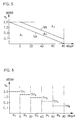
- Fig. 5 is a reference characteristic diagram showing the relationship between the field intensity and the speech or signal quality (bit error rate BERR) that is used as a reference for the analysis of the state of interference.
- the reference characteristic is prestored in the reference characteristic storage part 18 in Fig. 2.
- the straight line 5A indicates a theoretical relationship between the field intensity and the bit error rate BERR obtained by calculations in the ideal state mentioned above with respect to Fig. 3A
- the straight line 5B indicates an allowable range of interference predetermined relative to the theoretical relationship 5A, taking into account the signal quality degradation under the influence of fading and interference of radio waves.
- the measured points (E RL , BERR) defined by the field intensity (the reception level) E RL and the signal quality (BERR) measured by the mobile station MS are in an area A 1 under the straight line 5A in Fig. 5, it can be judged that the control channel of the mobile station is entirely free from the interference by control channels of other zones.
- the measured points (E RL , BERR) are in an area A 2 surrounded by the straight lines 5A and 5B, it can be judged that fading and the influence of interference are permissible.
- the measured points (E RL , BERR) are in an area A 3 above the straight line 5B, it can be judged that there exists an interference channel of a unpermissively high field intensity.
- the reference characteristic depicted in Fig. 5 is prestored in the reference characteristic storage part 18, then the measured points (E RL , BERR) received from individual mobile stations are compared with the reference characteristic of Fig. 5, and on the basis of the results obtained by statistically processing data on the results of comparison (results of judgment as to whether the measured value is abnormal or normal) made for a fixed period of time, a check is made to see if the influence on the channel of the zone by the interfering channels of other zones is within an allowable range (a range wherein the channel frequency need not be switched to another). This can be implemented using such methods as described below.
- the mobile station MS monitors if the timing for measurement has been reached (S 1 ). That is to say, the mobile station MS carries out measurement at regular time intervals, for example, upon each time-out of a preset timer.
- the measurement interval that is, the timer setting time is one or five minutes, for instance; it is also possible to set a short time for a small zone and a relatively long time for a large zone.
- Various other schemes can be employed; for instance, the measurement can be made upon each reception of a location registration report request that is regularly sent from the radio base station BS to the mobile station MS as described previously.
- the mobile station MS measures the field intensity of the downlink radio wave RW D from the radio base station BS, which is usually the radio wave of the control channel for receiving an incoming call, and its quality (the bit error rate, for instance) (S 2 ). Then, the mobile station MS reports the measured results to the radio base station BS with the uplink radio wave RW U , that is, over the control channel for call origination request use (S 3 ). The measured results may also be reported together with a report replying to the afore-mentioned report request from the radio base station BS.
- the radio base station BS waits for the report of measured results from each mobile station MS (S 4 ) and, upon each reception of the report, compares the measured results with the reference characteristic (S 5 ). That is to say, the base station BS compares the measured results with the reference characteristic prestored in the reference characteristic storage part 18 and makes a check to determine if the meausred point indicated by the measured results is abnormal or not, thereafter counting the number of meaured points and the number of abnormal points. Next, the base station BS checks whether a fixed period of time, for example, an hour has passed (S 6 ), and if not, goes back to step S 4 wherein to continue the reception of measured results.
- a fixed period of time for example, an hour has passed
- step S 6 If it is judged in step S 6 that the fixed period of time has passed, the meausred points acquired during the fixed period and the measured points decided as abnormal are statistically processed and a check is made to determine if the influence of the interference channel is within the allowed limit (S 7 ).
- the mobile station measures the field intensity and quality of the downlink radio wave and the radio base station processes the measured results; hence, even while the mobile radio communication system is in service, the state of interference can be evaluated, and when the state of interference varies due to a change in the radio wave environment, it is possible to detect the change in the state of interference following it in a short time.
- the mobile station measures the field intensity and quality of the downlink radio wave and the radio base station processes the measured results; hence, even while the mobile radio communication system is in service, the state of interference can be evaluated, and when the state of interference varies due to a change in the radio wave environment, it is possible to detect the change in the state of interference following it in a short time.
- the validity of the radiated radio wave is judged autonomously.
- the channel frequency used can autonomously be switched to another one of the other assigned frequencies when the base station detects the occurrence of an abnormality; that is, an autonomous base station with no centralized control device can be used.
- the base station Since the mobile station carries out the measurement, an abnormality in the service area (home zone) of the base station is detected from the user's standpoint, and the base station changes the state of propagation of its downlink radio wave by controlling its transmission output or the direction of an antenna, and by learning the state of interference from the measured results sent from the mobile station, an optimum state can be obtained.
Abstract
Description
- The present invention relates to a method for monitoring the state of interference of radio waves by each base station in a mobile radio communication system wherein the service area is divided into a plurality of zones and a plurality of radio channels of different frequencies are reused in respective zones over the entire service area with a minimum of co-channel interference. More particularly, the invention is directed to a method for monitoring the state of interference of radio waves by an autonomous base station which monitors the state of interference of radio waves in the radio channel of the same frequency as that of the radio channel of the base station and, when the state of interference goes down below a prescribed value, switches the radio channel to a different one or goes out of service.
- In a mobile radio communication system, as shown in Fig. 1, base stations BS1, BS2, ..., BSM are each provided in one of a plurality of zones Z1, Z2, ..., ZM forming a service area SA and, for example, radio channels of frequencies f1, f2, ..., f6 are assigned to the zones Z1, Z2..., ZM, respectively, as shown. In this instance, radio channels of the same frequency f1, for example, are assigned to zones distant from each other, such as Z1 and Z6, with particular attention to the suppression of what is called co-channel interference for efficient reuse of a plurality of radio channels of different frequencies over the entire service area to provide for increased utilization factor of frequency.
- In the conventional frequency assignment to respective zones, the distance between radio base stations using the same channel frequencies in the individual zones and their transmitting power are determined through theoretical calculation such that radio waves to each of the zones from the others are sufficiently attenuated to make the interference negligibly small.
- In this way, the conventional system reuses the frequencies f1, f2 , ..., f6 of the same set with a view to maximizing the utilization factor of radio waves. With such a conventional system, when an unexpected new propagation path appears or a propagation path existing so far disappears due to a change in the radio wave propagation environment, radio waves of the same frequency from two radio base stations may sometimes interfere with each other. To measure such interference, it is customary in the prior art to radiate radio waves from each of the two radio base stations one at a time, measure their electric field intensities and make a comprehensive analysis of the both measured results, thereby judging the range over which the radio waves from each base station exert an influence. Even after the mobile radio communication system is put into service, interference occurs or disappears due to a change in the radio wave propagation environment, for example, when the service area is extended and base stations are set up in new zones, when the frequency allocation scheme is partly or wholly modified, or when a large building or tower is put up or pulled down. Hence, it is necessary, after putting the mobile communication system into service, to check the state of interference with the radio channel of each of the zones using the same frequency;
to perform this for each zone, the transmission of radio waves from its base station needs to be stopped. Furthermore, the interference of radio waves is measured using a dedicated measurement device. - To learn the state of interference of radio waves in one of the zones using the same channel frequency, it is general practice in the prior art to measure the field intensity of radio waves that are caused to radiate one by one from other base stations; hence, much time is needed for the measurement and the judgement of the state of interference. In particular, while the system is in service, the field intensities of the radio waves from the other base stations are measured in a region wherein the radio wave from the base station of that one zone is considered to have a sufficiently high reception level, so that the transmission of the radio wave from the base station of that one zone must be stopped; however, since the transmission of radio wave cannot frequently be stopped while the system is in service, an appreciable amount of time is required to measure the field intensities of radido waves from other base stations. On this account, the measurement cannot be made rapidly following changes in the radio wave propagation environment, and hence gets far behind them, sometimes leaving a region of an undesired state of reception in the zone as it is for a considerably long period of time. Moreover, since the measurement is made on the radio wave radiated from only one of a plurality of base stations using the same frequency that are considered to interfere with each other, the mobile radio communication service is impaired during the measurement.
- It is therefore an object of the present invention to provide a method that permits easy, accurate monitoring of the state of co-channel interference even if the mobile radio communication system is in service.
- According to the present invention, a mobile station measures the field intensity and quality of a downlink radio wave thereto from a radio base station at regular intervals and reports back thereto the measured results, and the base station statistically processes the reported measured results into data on the radio wave emitted therefrom and makes a comprehensive analysis of such pieces of data, thereby monitoring the interference between the radio wave from the concerned radio base station and radio waves from other base stations using the same frequency as that of the former.
-
- Fig. 1 is a diagram schematically showing the zoning and frequency allocation in the service area of a mobile radio communication system;
- Fig. 2 is a block diagram illustrating an example of the zone configuration in the mobile radio communication system embodying this invention method;
- Fig. 3A is a graph showing theoretical curves of changes in the field intensity and the bit error rate with respect to the distance from a base station to a mobile station in the absence of interference waves;
- Fig. 3B is a graph showing changes in the bit error rate in the presence of interference waves in Fig. 3A;
- Fig. 4 is a diagram showing an example of the format of a control signal;
- Fig. 5 is a graph showing an example of a reference characteristic stored in a reference
characteristic storage part 18 in Fig. 2; - Fig. 6 is a graph for explaining an example of statistical processing of measured results;
- Fig. 7A is a flowchart illustrating an example of a procedure in a mobile station according to this invention method; and
- Fig. 7B is a flowchart illustrating an example of a procedure in a radio base station.
- In Fig. 2 there are illustrated an example of the configuration of the base station BS in one zone Zi of the mobile radio communication system of Fig. 1 and a mobile station MS when the present invention is applied thereto. The base station BS of the zone Zi has a radio transmitter/receiver 13, a comparison/
processing part 17 and a referencecharacteristic storage part 18. The radio base station BS is capable of two-way communications with the mobile station MS in the zone Zi through the use of a downlink radio wave (radio wave directed to the mobile station) RWD and an uplink radio wave (radio wave directed to the radio base station) RWU. The downlink radio wave RWD that is sent from the base station BS contains a downlink control channel and a downlink communication channel, whereas the uplink radio wave RWU that is sent from the mobile station contains an uplink control channel and an uplink communication channel different in frequency from those of the downlink radio wave RWD. - The base station BS transmits from the radio transmitter/receiver 13 a control signal and a communication signal over the downlink control channel and the downlink communication channel, respectively. The control signal that is sent over the downlink control channel has a predetermined format containing, for example, a call control signal for call setup use, a base station identifying signal, a peripheral zone identifying signal and a synchronizing signal. As in the prior art, the mobile station MS is always in a call waiting state (i.e., in a standby state) and is continuously or intermittently receiving the downlink control channel. Upon receiving an incoming call thereto via the control channel, the mobile station MS sends a control signal via the uplink control channel to the base station BS to acknowledge the reception of the incoming call, then receives the downlink communication channel following an instruction sent over the downlink control channel from the base station BS, and sends a communication signal over the uplink communication channel.
- According to the present invention, the field intensity (the receiving signal level) and signal quality (a bit error rate BERR, for instance) of the downlink control channel which the mobile station MS is receiving in each zone Zi are measured at desired time intervals and the measured results are sent to the base station BS over the uplink control channel. The base station BS acquires for a desired period of time data on the field intensity and the signal quality received from the mobile station, then statistically processes them and analyzes the state of interference in the channel used in that zone; when it is judged that the state of interference has become worse than a prescribed state, the channel frequency used in that zone is switched to a different frequency. To implement such a scheme, the radio base station BS is provided with the comparison/
processing part 17 and the referencecharacteristic storage part 18. - Depicted in Fig. 3A are curves Ea and Ba showing the relationships of the field intensity and the bit error rate measured in the mobile station MS of a certain zone to the distance thereto from the base station BSa in the case where the zone has no interference from base stations of other zones (that is, in an ideal state), the abscissa representing the distance from the base station BSa, the left-hand ordinate the field intensity and the right-hand ordinate the bit error rate BERR. In the absence of interference, the ideal curve Ea of the field intensity and the ideal curve Ba of the bit error rate with respect to the distance from the base station BSa can be calculated theoretically. As the distance from the base station BSa increases, the field intensity decreases and the bit error rate BERR increases little by little, and when the field intensity becomes smaller than a certain value (10 dBµV, for instance), the rate (gradient) at which the bit error rate BERR increase abruptly goes up. In accordance with the range of magnitude of the bit error rate BERR (for example, BERR<0.1%, 0.1≦BERR<0.3%, 0.3<BERR<1.0% and 1.0%<BERR), the distance from the base station BSa is divided into, for example, an error-free region D0, a small-error region D1, a medium-error region D2 and a large-error region D3. The region D0 is one that permits communication without hindrance; the error in the region D1 arises mainly from fading; the error in the region D2 results primarily from fading and noise; and the error in the region D3 is attributable principally to the degradation of the SN ratio of the receiving signal and this is a difficult-to-communicate region.
- In contrast to Fig. 3A, Fig. 3B shows examples of the field intensity and the bit error rate BERR measured with respect to the distance from the base station BSa in the case where a channel of the same frequency as that used in the base station BSa exists as an interference radio wave transmitted from a base station BSb of a zone distant from that of the base station BSa. The curve Eb shows the field intensity of the interference control channel from the base station BSb. In the presence of such an interference channel, the field intensity of a desired receiving control channel drops with distance from the base station BSa as indicated by the curve Ea, and at the same time, the field intensity of the interference control channel received from the base station BSb increases as indicated by the curve Eb; hence, the bit error rate BERR begins to abruptly go up at a position nearer to the base station BSa than in the case of Fig. 3A, as indicated by the curve Ba in Fig. 3B. As a result, the error-free region D0, the small-error region D1 and the medium-error region D2 shift toward the base station BSa and become smaller, whereas the large-error region D3 becomes larger toward the base station BSa.
- While in a call waiting state in the control channel of its visiting zone, the mobile station MS always monitors the reception levels of the call waiting control channel of the visiting zone and those of the control channels of peripheral zones at regular intervals so as to detect its migration into a new zone. According to the present invention, the mobile station MS measures the bit error rate BERR of the control signal received in the call waiting control channel and sends the measured value to the base station BS over the uplink control channel together with the reception level of the received control signal. For example, as shown in Fig. 4, the control signal has a predetermined format formed by iterations of a synchronizing word SW, a zone identifying code (referred to as color code) CC and control data DATA. The control data DATA differs with the type of the control signal, but the synchronizing word SW is predetermined in the system and the identifying code CC is predetermined for each zone. The bit error rate BERR can be measured by detecting a preknown specific signal or signals which are always contained in the control signal, such as any one of the synchronizing word SW, the zone identifying code CC and so forth, or a desired combination thereof. The measured reception level and bit error rate BERR can be sent to the base station BS by such methods as described below.
- (a) A signaling format exclusively for reporting the measured results is used to send them to the base station over the uplink control channel on demand or voluntarily at regular time intervals.
- (b) The measured results are sent, as part of a predetermined control signal for one of various uplink control channels now used in the existing communication systems, to the base station BS on demand or voluntarily at regular time intervals. The following schemes can be used to assemble the measured results into the control signal.
- * The measured results are assembled into a location registration signal that the mobile station MS transmits to the base station BS at regular time intervals.
- * During communication the measured results are assembled into a radio section control signal which is generated on a time-division basis at timing other than that of communication information. For example, in a personal digital cellular system, since a transmitting power control instruction is sent to the mobile station MS, the measured results are assembled into a signal that is used to report the field intensity of the downlink communication channel being measured by the mobile station MS.
- * The measured results are assembled into a call-connect control signal.
- The method (a) involves the setting of a new signaling format, and hence inevitably causes an unwanted increase in traffic. In contrast to this, the method (b) is to send the measured results assembled in the existing signal, with a negligibly small increase in traffic, and hence can easily be implemented.
- As described above, an interference control channel of the same frequency as that of the desired control channel will increase the bit error rate of the received signal in a desired control channel and degrade the signal quality accordingly. The degree of degradation differs with the field intensity ratio between the both channels interfering with each other.
- Fig. 5 is a reference characteristic diagram showing the relationship between the field intensity and the speech or signal quality (bit error rate BERR) that is used as a reference for the analysis of the state of interference. The reference characteristic is prestored in the reference
characteristic storage part 18 in Fig. 2. In Fig. 5 thestraight line 5A indicates a theoretical relationship between the field intensity and the bit error rate BERR obtained by calculations in the ideal state mentioned above with respect to Fig. 3A, and thestraight line 5B indicates an allowable range of interference predetermined relative to thetheoretical relationship 5A, taking into account the signal quality degradation under the influence of fading and interference of radio waves. That is, when the measured points (ERL, BERR) defined by the field intensity (the reception level) ERL and the signal quality (BERR) measured by the mobile station MS are in an area A1 under thestraight line 5A in Fig. 5, it can be judged that the control channel of the mobile station is entirely free from the interference by control channels of other zones. When the measured points (ERL, BERR) are in an area A2 surrounded by thestraight lines straight line 5B, it can be judged that there exists an interference channel of a unpermissively high field intensity. Where the influence of the interference is below the allowed limit, ordinary points of measurement are mostly found in the area A2 defined by thestraight lines - In the base station BS the reference characteristic depicted in Fig. 5 is prestored in the reference
characteristic storage part 18, then the measured points (ERL, BERR) received from individual mobile stations are compared with the reference characteristic of Fig. 5, and on the basis of the results obtained by statistically processing data on the results of comparison (results of judgment as to whether the measured value is abnormal or normal) made for a fixed period of time, a check is made to see if the influence on the channel of the zone by the interfering channels of other zones is within an allowable range (a range wherein the channel frequency need not be switched to another). This can be implemented using such methods as described below. - (I) First Method: For example, the reference characteristic indicated by the
straight line 5B in Fig. 5 is prestored in the referencecharacteristic storage part 18. Upon receiving the measured results (ERL, BERR) from each mobile station MS, the base station BS checks in the comparison/processingpart 17 as to whether the measured points (ERL, BERR) falls the area A3 or A1+A2 in Fig. 5. If the point is in the area A3, it is decided that interference is present (abnormal), and the measured point (ERL, BERR) is counted as an abnormal point. If the measured point is in the area A1+A2, it is decided that no interference exists (normal). The comparison/processingpart 17 counts the number of all points of measurement received for a fixed period of time (an hour, for instance) and the number of abnormal points detected, then calculates the ratio of the number of abnormal points to the number of all the points of measurement and, if the ratio is within a prescribed value, judges that the influence of interference is within the permissible limit. If the above-mentioned ratio is in excess of the prescribed value, then the comparison/processingpart 17 judges that the influence of interference is not permissible, in which case the channel frequency used is switched to another. - (II) Second Method: The field intensity in Fig. 5 is divided into regions R1, R2, ..., R5 of a predetermined width (20 dbµV) as shown in Fig. 6 and error rate threshold values TH1, TH2, ..., TH5 are predetermined for such regions. Each threshold value is, for example, the mean value of the
straight line 5B in Fig. 5 in each divided region. The comparison/processingpart 17 decides the region Ri (i=1, ..., 5) to which the field intensity ERL of the measured point (ERL, BERR) received from each mobile station MS is to belong, then compares the decided field intensity ERL with the threshold value THi of that region Ri and judges that the meausred point is normal or abnormal, depending on whether the field intensity ERL is smaller or larger than the threshold value THi. The comparison/processingpart 17 calculates the ratio Ci of the number of measured points judged as abnormal to the number Si of mesured points counted in each of the regions R1 to R5 for a fixed period of time, then compares a mean value of such ratios Ci (i=1, ..., 5) or their sum with a predetermined reference value, and if the former is larger than the latter, judges that the influence of the interference channel is not permissible. To obtain the mean or sum total of the ratios Ci, values weighted by weighting factors W1 to W5 predetermined for the respective regions R1 to R5 may be summed like ΣCiWi (i=1, ..., 5). - In the method (II), instead of using the threshold values TH1 to TH5 for the regions R1 to R5, it is also possible to divide the reference
straight line 5B by the regions R1 to R5 and make a check to see if each measured point belonging to each region Ri is above or below the divided reference straight line of that region. - The measurement by the mobile station MS and the statistical processing by the base station BS described above may be summarized as follows:
As shown in Fig. 7A, the mobile station MS monitors if the timing for measurement has been reached (S1). That is to say, the mobile station MS carries out measurement at regular time intervals, for example, upon each time-out of a preset timer. The measurement interval, that is, the timer setting time is one or five minutes, for instance; it is also possible to set a short time for a small zone and a relatively long time for a large zone. Various other schemes can be employed; for instance, the measurement can be made upon each reception of a location registration report request that is regularly sent from the radio base station BS to the mobile station MS as described previously. - When the timing for measurement is reached, the mobile station MS measures the field intensity of the downlink radio wave RWD from the radio base station BS, which is usually the radio wave of the control channel for receiving an incoming call, and its quality (the bit error rate, for instance) (S2). Then, the mobile station MS reports the measured results to the radio base station BS with the uplink radio wave RWU, that is, over the control channel for call origination request use (S3). The measured results may also be reported together with a report replying to the afore-mentioned report request from the radio base station BS.
- As shown in Fig. 7B, the radio base station BS waits for the report of measured results from each mobile station MS (S4) and, upon each reception of the report, compares the measured results with the reference characteristic (S5). That is to say, the base station BS compares the measured results with the reference characteristic prestored in the reference
characteristic storage part 18 and makes a check to determine if the meausred point indicated by the measured results is abnormal or not, thereafter counting the number of meaured points and the number of abnormal points. Next, the base station BS checks whether a fixed period of time, for example, an hour has passed (S6), and if not, goes back to step S4 wherein to continue the reception of measured results. If it is judged in step S6 that the fixed period of time has passed, the meausred points acquired during the fixed period and the measured points decided as abnormal are statistically processed and a check is made to determine if the influence of the interference channel is within the allowed limit (S7). - As described above, according to the present invention, the mobile station measures the field intensity and quality of the downlink radio wave and the radio base station processes the measured results; hence, even while the mobile radio communication system is in service, the state of interference can be evaluated, and when the state of interference varies due to a change in the radio wave environment, it is possible to detect the change in the state of interference following it in a short time. Thus, there is no need of management control via a centralized control device or artificial management.
- In the mobile radio communication system that autonomously determines the frequencies of the radio waves (the channels) which the base stations radiate, the validity of the radiated radio wave is judged autonomously.
- With a plurality of frequencies assigned to the base station, the channel frequency used can autonomously be switched to another one of the other assigned frequencies when the base station detects the occurrence of an abnormality; that is, an autonomous base station with no centralized control device can be used.
- Since the mobile station carries out the measurement, an abnormality in the service area (home zone) of the base station is detected from the user's standpoint, and the base station changes the state of propagation of its downlink radio wave by controlling its transmission output or the direction of an antenna, and by learning the state of interference from the measured results sent from the mobile station, an optimum state can be obtained.
- It will be apparent that many modifications and variations may be effected without departing from the scope of the novel concepts of the present invention.
Claims (8)
- A method for monitoring the state of interference in each zone of a mobile radio communication system wherein a mobile station in each zone performs communication via a base station of said each zone, said method comprising the steps of:(a) periodically measuring, by said mobile station, the field intensity and quality of a downlink radio wave from said base station;(b) reporting measured results from said mobile station to said base station;(c) collecting, by said base station for a predetermined period of time, said measured results reported from said mobile station and statistically processing said collected measured results into data about the state of interference; and(d) evaluating said data about said state of interference, thereby judging the state of interference between the radio wave from said base station and other radio waves of the same frequency as that of said radio wave from said base station.
- The method of claim 1, wherein said quality if a bit error rate.
- The method of claim 1, wherein said downlink radio wave is a downlink control channel.
- The method of claim 1, wherein said step (b) comprises a step of requesting said mobile station from said base station to send thereto said measured results, and a step of sending said measured results from said mobile station to said base station in response to said request.
- The method of claim 1, wherein said step (b) comprises a step of voluntarily sending said measured results from said mobile station at regular time intervals.
- The method of claim 1, wherein said step (c) comprises a step of comparing said measured results with a predetermined reference characteristic to judge whether said measured results are abnormal or not.
- The method of claim 6, wherein said reference characteristic is a characteristic predetermined on the basis of a characteristic representing an ideal relationship between field intensity and bit error rate, it is judged whether said measured results are abnormal, by comparing said measured results with said bit error rate defined by said reference characteristic, and the rate of the number of measured results judged as abnormal to the number of measured results collected for said predetermined period of time is used as an index indicating said state of interference.
- The method of claim 6, wherein said reference characteristic is defined by error rate threshold values determined on the basis of an ideal characteristic indicating an ideal relationship between field intensity and bit error rate in respective intensity regions obtained by dividing field intensity, and which further comprises a step of deciding the intensity region to which said measured results belong, comparing said measured results with said threshold value of said intensity region to determine whether said measured results are abnormal or not, calculating the rate of the number of measured results determined as abnormal to the number of measured results belonging to each of said intensity region during said predetermined period of time, and weighting said rates with predetermined weighting factors, respectively, and adding said weighted rates to obtain an index indicating said state of interference.
Applications Claiming Priority (3)
| Application Number | Priority Date | Filing Date | Title |
|---|---|---|---|
| JP327795/94 | 1994-12-28 | ||
| JP32779594 | 1994-12-28 | ||
| JP32779594 | 1994-12-28 |
Publications (3)
| Publication Number | Publication Date |
|---|---|
| EP0720407A2 true EP0720407A2 (en) | 1996-07-03 |
| EP0720407A3 EP0720407A3 (en) | 1997-11-05 |
| EP0720407B1 EP0720407B1 (en) | 2002-04-17 |
Family
ID=18203082
Family Applications (1)
| Application Number | Title | Priority Date | Filing Date |
|---|---|---|---|
| EP95120162A Expired - Lifetime EP0720407B1 (en) | 1994-12-28 | 1995-12-20 | Method for monitoring the state of interference by a base station of a mobile radio communication system |
Country Status (3)
| Country | Link |
|---|---|
| US (1) | US5603093A (en) |
| EP (1) | EP0720407B1 (en) |
| DE (1) | DE69526420T2 (en) |
Cited By (26)
| Publication number | Priority date | Publication date | Assignee | Title |
|---|---|---|---|---|
| WO1997033446A1 (en) * | 1996-03-07 | 1997-09-12 | Nokia Telecommunications Oy | Remote test of a wireless subscriber connection |
| WO1997033447A1 (en) * | 1996-03-07 | 1997-09-12 | Nokia Telecommunications Oy | Method and system for testing the condition of a subscriber station in a radio system |
| WO1998014025A1 (en) * | 1996-09-27 | 1998-04-02 | Nokia Telecommunications Oy | Adaptive frequency planning in a cellular network |
| WO1998027763A2 (en) * | 1996-12-19 | 1998-06-25 | Telefonaktiebolaget Lm Ericsson (Publ) | Estimating downlink interference in a cellular communications system |
| WO1998029961A2 (en) * | 1996-12-30 | 1998-07-09 | Nokia Telecommunications Oy | A cellular radio system and a method for measuring the interference level |
| WO1998032302A1 (en) * | 1997-01-22 | 1998-07-23 | Telefonaktiebolaget Lm Ericsson (Publ) | A method and apparatus for estimating path loss in a radio communications system |
| WO1998043455A2 (en) * | 1997-03-25 | 1998-10-01 | Northern Telecom Limited | Method and wireless terminal for monitoring communications and providing network with terminal operation information |
| WO1998049853A1 (en) * | 1997-04-25 | 1998-11-05 | British Telecommunications Public Limited Company | Wireless communications network planning |
| WO1998053630A1 (en) * | 1997-05-22 | 1998-11-26 | Telefonaktiebolaget Lm Ericsson | Speech quality measurement in mobile telecommunication networks based on radio link parameters |
| WO1998053621A2 (en) * | 1997-05-19 | 1998-11-26 | Qualcomm Incorporated | Method and apparatus for optimization of a cellular network |
| GB2337425A (en) * | 1998-05-14 | 1999-11-17 | Simoco Int Ltd | Radio channel quality estimation |
| US6201960B1 (en) * | 1997-06-24 | 2001-03-13 | Telefonaktiebolaget Lm Ericsson (Publ) | Speech quality measurement based on radio link parameters and objective measurement of received speech signals |
| US6201802B1 (en) | 1997-08-29 | 2001-03-13 | Qualcomm Inc. | Method and apparatus for analyzing base station timing |
| WO2001063958A1 (en) * | 2000-02-25 | 2001-08-30 | Matsushita Electric Industrial Co.,Ltd. | Mobile station apparatus, base station apparatus, and method for allotting radio communication channels |
| WO2002009312A2 (en) * | 2000-07-20 | 2002-01-31 | Telefonaktiebolaget Lm Ericsson (Publ) | Systems and methods for measuring interference reciprocity between uplink and downlink directions in a wireless communications system |
| US6922551B1 (en) | 1998-07-15 | 2005-07-26 | Telefonaktiebolaget L M Ericsson (Publ) | Interference prevention in a radio communications system |
| WO2008031112A2 (en) * | 2006-09-08 | 2008-03-13 | Qualcomm Incorporated | Method and apparatus for determining a radiated performance of a wireless device |
| WO2008088737A3 (en) * | 2007-01-12 | 2008-11-20 | Interdigital Tech Corp | Method and apparatus for measuring interference in wireless stations |
| EP2091283A1 (en) | 1997-11-03 | 2009-08-19 | Qualcomm Incorporated | Method and apparatus for high rate packet data transmission |
| EP2187698A1 (en) * | 2007-08-13 | 2010-05-19 | NTT DoCoMo, Inc. | Mobile communication system, general base station device, base station device, and base station status control method |
| US7848284B2 (en) | 1997-11-03 | 2010-12-07 | Qualcomm Incorporated | Method and apparatus for high rate packet data transmission |
| US8064409B1 (en) | 1999-08-25 | 2011-11-22 | Qualcomm Incorporated | Method and apparatus using a multi-carrier forward link in a wireless communication system |
| US8811200B2 (en) | 2009-09-22 | 2014-08-19 | Qualcomm Incorporated | Physical layer metrics to support adaptive station-dependent channel state information feedback rate in multi-user communication systems |
| US9107109B2 (en) | 2000-10-25 | 2015-08-11 | Qualcomm Incorporated | Method and apparatus for determining a data rate in a high rate packet data wireless communications system |
| US9118387B2 (en) | 1997-11-03 | 2015-08-25 | Qualcomm Incorporated | Pilot reference transmission for a wireless communication system |
| US9426821B2 (en) | 2000-10-25 | 2016-08-23 | Qualcomm Incorporated | Method and apparatus for high rate packet data and low delay data transmissions |
Families Citing this family (33)
| Publication number | Priority date | Publication date | Assignee | Title |
|---|---|---|---|---|
| FR2739512B1 (en) * | 1995-10-03 | 1997-10-31 | France Telecom | MODELING INTERFERENCE IN A CELLULAR RADIOTELEPHONE NETWORK |
| JP3415978B2 (en) * | 1995-11-24 | 2003-06-09 | 富士通株式会社 | Carrier switching method |
| JPH09261153A (en) * | 1996-03-27 | 1997-10-03 | Aiwa Co Ltd | Portable terminal equipment |
| US6009332A (en) * | 1996-08-28 | 1999-12-28 | Telefonaktiebolaget Lm Ericsson | Method and system for autonomously allocating a frequency hopping traffic channel in a private radio system |
| US6405043B1 (en) * | 1997-07-02 | 2002-06-11 | Scoreboard, Inc. | Method to characterize the prospective or actual level of interference at a point, in a sector, and throughout a cellular system |
| KR100244198B1 (en) | 1997-12-09 | 2000-02-01 | 윤종용 | Air interference measurement set of base stations and method thereof |
| JPH11282684A (en) | 1998-03-27 | 1999-10-15 | Canon Inc | Image processor, method for controlling image processor and storage medium |
| JP3241672B2 (en) * | 1998-07-31 | 2001-12-25 | 三菱電機株式会社 | Interference wave detection device and interference wave detection method |
| GB9817292D0 (en) * | 1998-08-07 | 1998-10-07 | Nokia Mobile Phones Ltd | Digital video coding |
| FI982121A (en) * | 1998-09-30 | 2000-03-31 | Nokia Networks Oy | Power control in the radio system |
| JP3512154B2 (en) * | 1999-01-25 | 2004-03-29 | 松下電器産業株式会社 | Base station equipment |
| US6556553B1 (en) * | 1999-04-12 | 2003-04-29 | Intermec Ip Corp. | Method for determining when a communication device should rate shift or roam in a wireless environment |
| US6775544B2 (en) | 1999-06-03 | 2004-08-10 | At&T Wireless Services, Inc. | Automatic diagnostic for detection of interference in wireless communication system |
| JP3349477B2 (en) * | 1999-09-08 | 2002-11-25 | 三洋電機株式会社 | Mobile communication device, mobile communication system, and communication channel assignment request method |
| US6621804B1 (en) | 1999-10-07 | 2003-09-16 | Qualcomm Incorporated | Method and apparatus for predicting favored supplemental channel transmission slots using transmission power measurements of a fundamental channel |
| EP1156609A1 (en) * | 2000-05-15 | 2001-11-21 | TELEFONAKTIEBOLAGET LM ERICSSON (publ) | Transmission quality measurement in a communication network |
| US20030040277A1 (en) * | 2000-07-18 | 2003-02-27 | Deats Bradley W. | Apparatus and method for measuring and identifying sources of communications interference |
| US7366471B1 (en) * | 2000-08-31 | 2008-04-29 | Intel Corporation | Mitigating interference between wireless systems |
| DE60108225T2 (en) * | 2001-05-08 | 2005-12-08 | Agere Systems Guardian Corp., Orlando | Dynamic frequency selection in a wireless local area network with channel exchange between access points |
| US8977284B2 (en) | 2001-10-04 | 2015-03-10 | Traxcell Technologies, LLC | Machine for providing a dynamic data base of geographic location information for a plurality of wireless devices and process for making same |
| US7068976B2 (en) * | 2001-12-18 | 2006-06-27 | Ericsson Inc. | Method of verifying operation of listening control channel |
| US7039017B2 (en) * | 2001-12-28 | 2006-05-02 | Texas Instruments Incorporated | System and method for detecting and locating interferers in a wireless communication system |
| US6859642B2 (en) * | 2002-04-29 | 2005-02-22 | Nokia Corporation | Calibration of signal strength measurements in a cellular communications system |
| JP4069034B2 (en) * | 2003-07-31 | 2008-03-26 | 松下電器産業株式会社 | Wireless transmission device, wireless reception device, wireless communication system, wireless transmission method, and wireless reception method |
| US7493135B2 (en) * | 2004-04-02 | 2009-02-17 | Lg Electronics Inc. | Transmission method for downlink control signal in MIMO system |
| WO2005099123A1 (en) * | 2004-04-07 | 2005-10-20 | Lg Electronics Inc. | Transmission method of downlink control signal for mimo system |
| CN101076958A (en) * | 2004-10-19 | 2007-11-21 | 夏普株式会社 | Base station apparatus, wireless communication system, and wireless transmission method |
| JP2007316070A (en) * | 2006-05-22 | 2007-12-06 | Polaris Wireless Inc | Method for predicting position of wireless terminal |
| KR101371148B1 (en) * | 2007-08-27 | 2014-03-10 | 삼성전자주식회사 | Base station, mobile station for processing wireless communication each other, and method for controlling the same |
| ATE535118T1 (en) | 2008-03-12 | 2011-12-15 | Sequans Comm | METHOD FOR CONTROLLING INTERFERENCE GENERATED BY A MOBILE STATION ON NEIGHBOR BASE STATIONS |
| JP5217688B2 (en) * | 2008-06-30 | 2013-06-19 | 富士通セミコンダクター株式会社 | Wireless terminal device, semiconductor device, and communication system |
| JP5233454B2 (en) * | 2008-07-08 | 2013-07-10 | 富士通株式会社 | Mobile terminal station and reception quality measuring method |
| CN116634473B (en) * | 2023-07-21 | 2023-10-10 | 中国铁塔股份有限公司云南省分公司 | Method and device for predicting failure of power failure and service withdrawal of wireless station |
Citations (2)
| Publication number | Priority date | Publication date | Assignee | Title |
|---|---|---|---|---|
| EP0431956A2 (en) * | 1989-12-07 | 1991-06-12 | Motorola, Inc. | Cellular radiotelephone diagnostic system |
| US5375123A (en) * | 1993-02-05 | 1994-12-20 | Telefonakitebolaget L. M. Ericsson | Allocation of channels using interference estimation |
Family Cites Families (4)
| Publication number | Priority date | Publication date | Assignee | Title |
|---|---|---|---|---|
| JPH02312492A (en) * | 1989-05-29 | 1990-12-27 | Nec Corp | Channel assignment method in mobile communication system and learning system for base station arrangement information |
| SE465004B (en) * | 1989-12-18 | 1991-07-08 | Televerket | METHOD FOR DETERMINING MULTIPLE INTERFERENCES IN A MOBILE RADIO SYSTEM |
| SE469580B (en) * | 1992-08-18 | 1993-07-26 | Televerket | PROCEDURE MAKES C / I DENSITY ESTIMATE AND INTERFERENCE LIKELIHOOD |
| US5506869A (en) * | 1994-10-27 | 1996-04-09 | Northern Telecom Limited | Methods and apparatus for estimating carrier-to-interference ratios at cellular radio base stations |
-
1995
- 1995-12-13 US US08/571,649 patent/US5603093A/en not_active Expired - Lifetime
- 1995-12-20 EP EP95120162A patent/EP0720407B1/en not_active Expired - Lifetime
- 1995-12-20 DE DE69526420T patent/DE69526420T2/en not_active Expired - Lifetime
Patent Citations (2)
| Publication number | Priority date | Publication date | Assignee | Title |
|---|---|---|---|---|
| EP0431956A2 (en) * | 1989-12-07 | 1991-06-12 | Motorola, Inc. | Cellular radiotelephone diagnostic system |
| US5375123A (en) * | 1993-02-05 | 1994-12-20 | Telefonakitebolaget L. M. Ericsson | Allocation of channels using interference estimation |
Cited By (64)
| Publication number | Priority date | Publication date | Assignee | Title |
|---|---|---|---|---|
| WO1997033447A1 (en) * | 1996-03-07 | 1997-09-12 | Nokia Telecommunications Oy | Method and system for testing the condition of a subscriber station in a radio system |
| US6169883B1 (en) | 1996-03-07 | 2001-01-02 | Nokia Telecommunications Oy | Remote test of a subscriber connection in a system implementing a wireless subscriber connection |
| WO1997033446A1 (en) * | 1996-03-07 | 1997-09-12 | Nokia Telecommunications Oy | Remote test of a wireless subscriber connection |
| WO1998014025A1 (en) * | 1996-09-27 | 1998-04-02 | Nokia Telecommunications Oy | Adaptive frequency planning in a cellular network |
| US6253086B1 (en) | 1996-09-27 | 2001-06-26 | Nokia Telecommunications Oy | Adaptive frequency planning in a cellular network |
| CN1098017C (en) * | 1996-09-27 | 2003-01-01 | 诺基亚电信公司 | Adaptive frequency planning in a cellular network |
| AU746136B2 (en) * | 1996-12-19 | 2002-04-18 | Telefonaktiebolaget Lm Ericsson (Publ) | Estimating downlink interference in a cellular communications system |
| WO1998027763A2 (en) * | 1996-12-19 | 1998-06-25 | Telefonaktiebolaget Lm Ericsson (Publ) | Estimating downlink interference in a cellular communications system |
| US6137991A (en) * | 1996-12-19 | 2000-10-24 | Ericsson Telefon Ab L M | Estimating downlink interference in a cellular communications system |
| WO1998027763A3 (en) * | 1996-12-19 | 1998-08-06 | Ericsson Telefon Ab L M | Estimating downlink interference in a cellular communications system |
| WO1998029961A2 (en) * | 1996-12-30 | 1998-07-09 | Nokia Telecommunications Oy | A cellular radio system and a method for measuring the interference level |
| WO1998029961A3 (en) * | 1996-12-30 | 1998-08-27 | Nokia Telecommunications Oy | A cellular radio system and a method for measuring the interference level |
| AU728831B2 (en) * | 1996-12-30 | 2001-01-18 | Nokia Telecommunications Oy | A cellular radio system and a method for measuring the interference level |
| WO1998032302A1 (en) * | 1997-01-22 | 1998-07-23 | Telefonaktiebolaget Lm Ericsson (Publ) | A method and apparatus for estimating path loss in a radio communications system |
| US6137993A (en) * | 1997-01-22 | 2000-10-24 | Telefonaktiebolaget Lm Ericsson | Method and apparatus for estimating path loss in a radio communications system |
| WO1998043455A2 (en) * | 1997-03-25 | 1998-10-01 | Northern Telecom Limited | Method and wireless terminal for monitoring communications and providing network with terminal operation information |
| WO1998043455A3 (en) * | 1997-03-25 | 1999-04-01 | Northern Telecom Ltd | Method and wireless terminal for monitoring communications and providing network with terminal operation information |
| US6088588A (en) * | 1997-03-25 | 2000-07-11 | Nortel Networks Corporation | Method and wireless terminal for monitoring communications and providing network with terminal operation information |
| GB2342538B (en) * | 1997-04-25 | 2002-03-06 | British Telecomm | Wireless communications network planning |
| GB2342538A (en) * | 1997-04-25 | 2000-04-12 | British Telecomm | Wireless communications network planning |
| WO1998049853A1 (en) * | 1997-04-25 | 1998-11-05 | British Telecommunications Public Limited Company | Wireless communications network planning |
| US6253065B1 (en) | 1997-04-25 | 2001-06-26 | British Telecommunications Public Limited Company | Wireless communications network planning |
| WO1998053621A2 (en) * | 1997-05-19 | 1998-11-26 | Qualcomm Incorporated | Method and apparatus for optimization of a cellular network |
| WO1998053621A3 (en) * | 1997-05-19 | 1999-02-25 | Qualcomm Inc | Method and apparatus for optimization of a cellular network |
| US6157830A (en) * | 1997-05-22 | 2000-12-05 | Telefonaktiebolaget Lm Ericsson | Speech quality measurement in mobile telecommunication networks based on radio link parameters |
| GB2342539A (en) * | 1997-05-22 | 2000-04-12 | Ericsson Telefon Ab L M | Speech quality measurement in mobile telecommunication networks based on radio link parameters |
| GB2342539B (en) * | 1997-05-22 | 2002-06-12 | Ericsson Telefon Ab L M | Speech quality measurement in mobile telecommunication networks based on radio link parameters |
| AU742933B2 (en) * | 1997-05-22 | 2002-01-17 | Telefonaktiebolaget Lm Ericsson (Publ) | Speech quality measurement in mobile telecommunication networks based on radio link parameters |
| WO1998053630A1 (en) * | 1997-05-22 | 1998-11-26 | Telefonaktiebolaget Lm Ericsson | Speech quality measurement in mobile telecommunication networks based on radio link parameters |
| US6201960B1 (en) * | 1997-06-24 | 2001-03-13 | Telefonaktiebolaget Lm Ericsson (Publ) | Speech quality measurement based on radio link parameters and objective measurement of received speech signals |
| US6201802B1 (en) | 1997-08-29 | 2001-03-13 | Qualcomm Inc. | Method and apparatus for analyzing base station timing |
| US8077655B2 (en) | 1997-11-03 | 2011-12-13 | Qualcomm Incorporated | Method and apparatus for high rate packet data transmission |
| US8351372B2 (en) | 1997-11-03 | 2013-01-08 | Qualcomm Incorporated | Method and apparatus for high rate packet data transmission |
| US9124344B2 (en) | 1997-11-03 | 2015-09-01 | Qualcomm Incorporated | Pilot reference transmission for a wireless communication system |
| US9118387B2 (en) | 1997-11-03 | 2015-08-25 | Qualcomm Incorporated | Pilot reference transmission for a wireless communication system |
| US9001735B2 (en) | 1997-11-03 | 2015-04-07 | Qualcomm Incorporated | Method and apparatus for high rate packet data transmission |
| US8311027B2 (en) | 1997-11-03 | 2012-11-13 | Qualcomm Incorporated | Method and apparatus for high rate packet data transmission |
| US8189540B2 (en) | 1997-11-03 | 2012-05-29 | Qualcomm Incorporated | Method and apparatus for high rate packet data transmission |
| US8089924B2 (en) | 1997-11-03 | 2012-01-03 | Qualcomm Incorporated | Method and apparatus for high rate packet data transmission |
| US8009625B2 (en) | 1997-11-03 | 2011-08-30 | Qualcomm Incorporated | Method and apparatus for high rate packet data transmission |
| US8005042B2 (en) | 1997-11-03 | 2011-08-23 | Qualcomm Incorporated | Method and apparatus for high rate packet data transmission |
| EP2091283A1 (en) | 1997-11-03 | 2009-08-19 | Qualcomm Incorporated | Method and apparatus for high rate packet data transmission |
| US7995531B2 (en) | 1997-11-03 | 2011-08-09 | Qualcomm Incorporated | Method and apparatus for high rate packet data transmission |
| US7848284B2 (en) | 1997-11-03 | 2010-12-07 | Qualcomm Incorporated | Method and apparatus for high rate packet data transmission |
| US7848283B2 (en) | 1997-11-03 | 2010-12-07 | Qualcomm Incorporated | Method and apparatus for high rate packet data transmission |
| US7848285B2 (en) | 1997-11-03 | 2010-12-07 | Qualcomm Incorporated | Method and apparatus for high rate packet data transmission |
| US7848282B2 (en) | 1997-11-03 | 2010-12-07 | Qualcomm Incorporated | Method and apparatus for high rate packet data transmission |
| GB2337425B (en) * | 1998-05-14 | 2000-12-13 | Simoco Int Ltd | Radio channel quality estimation |
| GB2337425A (en) * | 1998-05-14 | 1999-11-17 | Simoco Int Ltd | Radio channel quality estimation |
| US6922551B1 (en) | 1998-07-15 | 2005-07-26 | Telefonaktiebolaget L M Ericsson (Publ) | Interference prevention in a radio communications system |
| US8064409B1 (en) | 1999-08-25 | 2011-11-22 | Qualcomm Incorporated | Method and apparatus using a multi-carrier forward link in a wireless communication system |
| WO2001063958A1 (en) * | 2000-02-25 | 2001-08-30 | Matsushita Electric Industrial Co.,Ltd. | Mobile station apparatus, base station apparatus, and method for allotting radio communication channels |
| US6684061B1 (en) | 2000-07-20 | 2004-01-27 | Telefonaktiebolaget Lm Ericsson (Publ) | Systems and methods for measuring interference reciprocity between uplink and downlink directions in a wireless communications system |
| WO2002009312A2 (en) * | 2000-07-20 | 2002-01-31 | Telefonaktiebolaget Lm Ericsson (Publ) | Systems and methods for measuring interference reciprocity between uplink and downlink directions in a wireless communications system |
| WO2002009312A3 (en) * | 2000-07-20 | 2002-06-27 | Ericsson Telefon Ab L M | Systems and methods for measuring interference reciprocity between uplink and downlink directions in a wireless communications system |
| US9107109B2 (en) | 2000-10-25 | 2015-08-11 | Qualcomm Incorporated | Method and apparatus for determining a data rate in a high rate packet data wireless communications system |
| US9426821B2 (en) | 2000-10-25 | 2016-08-23 | Qualcomm Incorporated | Method and apparatus for high rate packet data and low delay data transmissions |
| WO2008031112A3 (en) * | 2006-09-08 | 2008-04-24 | Qualcomm Inc | Method and apparatus for determining a radiated performance of a wireless device |
| WO2008031112A2 (en) * | 2006-09-08 | 2008-03-13 | Qualcomm Incorporated | Method and apparatus for determining a radiated performance of a wireless device |
| US7925253B2 (en) | 2006-09-08 | 2011-04-12 | Qualcomm Incorporated | Radiated performance of a wireless device |
| WO2008088737A3 (en) * | 2007-01-12 | 2008-11-20 | Interdigital Tech Corp | Method and apparatus for measuring interference in wireless stations |
| EP2187698A1 (en) * | 2007-08-13 | 2010-05-19 | NTT DoCoMo, Inc. | Mobile communication system, general base station device, base station device, and base station status control method |
| EP2187698A4 (en) * | 2007-08-13 | 2015-03-18 | Ntt Docomo Inc | Mobile communication system, general base station device, base station device, and base station status control method |
| US8811200B2 (en) | 2009-09-22 | 2014-08-19 | Qualcomm Incorporated | Physical layer metrics to support adaptive station-dependent channel state information feedback rate in multi-user communication systems |
Also Published As
| Publication number | Publication date |
|---|---|
| US5603093A (en) | 1997-02-11 |
| EP0720407B1 (en) | 2002-04-17 |
| EP0720407A3 (en) | 1997-11-05 |
| DE69526420D1 (en) | 2002-05-23 |
| DE69526420T2 (en) | 2002-10-31 |
Similar Documents
| Publication | Publication Date | Title |
|---|---|---|
| US5603093A (en) | Method for monitoring the state of interference by a base station of a mobile radio communication system | |
| US5548808A (en) | Method for performing a handoff in a communication system | |
| EP0616750B1 (en) | Handover decision algorithm using power budget values | |
| US5594949A (en) | Mobile assisted channel allocation | |
| EP1320277B1 (en) | Call admission control method and mobile station device for cdma mobile communication system | |
| KR100319309B1 (en) | Mobile communication system | |
| US6175745B1 (en) | Initial transmit power determination in a radiocommunication system | |
| CN100486377C (en) | Micro-processor of distributing radio channel | |
| US5542097A (en) | Method and system for confirming the identity of a target cell for handoff | |
| US7092732B2 (en) | Radio-communication control method and equipment | |
| EP0648028B1 (en) | Mobile communication system | |
| US6351649B1 (en) | Mobile communication system | |
| EP0786914A2 (en) | A space division multiple access radio communication system and method for allocating channels therein | |
| PL186647B1 (en) | Method of and system for estimating descending interferences in a cellular telecommunication network | |
| US5542098A (en) | Method of handover in a cellular system | |
| US6081727A (en) | Transmission power control system capable of disabling communication of a mobile terminal which carries out an abnormal operation | |
| JP2992563B2 (en) | Mobile communication system | |
| JP2965057B2 (en) | Method for monitoring interference state in base station of mobile communication system | |
| US6434386B1 (en) | Method and system for monitoring power output in transceivers | |
| EP1075157B1 (en) | Radio link allocation judging method in mobile communication system and radio link controller | |
| JP3707952B2 (en) | Wireless communication system and control method thereof | |
| WO1998019474A2 (en) | A method for accessing a microcell using analog control channels | |
| US6697616B1 (en) | Method and base station for functional testing of a transmission and reception path | |
| JP2985948B2 (en) | Mobile communication system | |
| WO1998033344A1 (en) | Measuring usage of cellular mobile telephones |
Legal Events
| Date | Code | Title | Description |
|---|---|---|---|
| PUAI | Public reference made under article 153(3) epc to a published international application that has entered the european phase |
Free format text: ORIGINAL CODE: 0009012 |
|
| 17P | Request for examination filed |
Effective date: 19951220 |
|
| AK | Designated contracting states |
Kind code of ref document: A2 Designated state(s): DE GB SE |
|
| PUAL | Search report despatched |
Free format text: ORIGINAL CODE: 0009013 |
|
| AK | Designated contracting states |
Kind code of ref document: A3 Designated state(s): DE GB SE |
|
| 17Q | First examination report despatched |
Effective date: 20000302 |
|
| GRAG | Despatch of communication of intention to grant |
Free format text: ORIGINAL CODE: EPIDOS AGRA |
|
| GRAG | Despatch of communication of intention to grant |
Free format text: ORIGINAL CODE: EPIDOS AGRA |
|
| GRAH | Despatch of communication of intention to grant a patent |
Free format text: ORIGINAL CODE: EPIDOS IGRA |
|
| REG | Reference to a national code |
Ref country code: GB Ref legal event code: IF02 |
|
| GRAH | Despatch of communication of intention to grant a patent |
Free format text: ORIGINAL CODE: EPIDOS IGRA |
|
| GRAA | (expected) grant |
Free format text: ORIGINAL CODE: 0009210 |
|
| AK | Designated contracting states |
Kind code of ref document: B1 Designated state(s): DE GB SE |
|
| REF | Corresponds to: |
Ref document number: 69526420 Country of ref document: DE Date of ref document: 20020523 |
|
| PLBE | No opposition filed within time limit |
Free format text: ORIGINAL CODE: 0009261 |
|
| STAA | Information on the status of an ep patent application or granted ep patent |
Free format text: STATUS: NO OPPOSITION FILED WITHIN TIME LIMIT |
|
| 26N | No opposition filed |
Effective date: 20030120 |
|
| PGFP | Annual fee paid to national office [announced via postgrant information from national office to epo] |
Ref country code: GB Payment date: 20141217 Year of fee payment: 20 Ref country code: SE Payment date: 20141211 Year of fee payment: 20 Ref country code: DE Payment date: 20141216 Year of fee payment: 20 |
|
| REG | Reference to a national code |
Ref country code: DE Ref legal event code: R071 Ref document number: 69526420 Country of ref document: DE |
|
| REG | Reference to a national code |
Ref country code: GB Ref legal event code: PE20 Expiry date: 20151219 |
|
| PG25 | Lapsed in a contracting state [announced via postgrant information from national office to epo] |
Ref country code: GB Free format text: LAPSE BECAUSE OF EXPIRATION OF PROTECTION Effective date: 20151219 |
|
| REG | Reference to a national code |
Ref country code: SE Ref legal event code: EUG |