EP0718668A2 - Short length optical space switch - Google Patents
Short length optical space switch Download PDFInfo
- Publication number
- EP0718668A2 EP0718668A2 EP95119685A EP95119685A EP0718668A2 EP 0718668 A2 EP0718668 A2 EP 0718668A2 EP 95119685 A EP95119685 A EP 95119685A EP 95119685 A EP95119685 A EP 95119685A EP 0718668 A2 EP0718668 A2 EP 0718668A2
- Authority
- EP
- European Patent Office
- Prior art keywords
- waveguide
- curved
- optical space
- space switch
- regions
- Prior art date
- Legal status (The legal status is an assumption and is not a legal conclusion. Google has not performed a legal analysis and makes no representation as to the accuracy of the status listed.)
- Withdrawn
Links
Images
Classifications
-
- G—PHYSICS
- G02—OPTICS
- G02F—OPTICAL DEVICES OR ARRANGEMENTS FOR THE CONTROL OF LIGHT BY MODIFICATION OF THE OPTICAL PROPERTIES OF THE MEDIA OF THE ELEMENTS INVOLVED THEREIN; NON-LINEAR OPTICS; FREQUENCY-CHANGING OF LIGHT; OPTICAL LOGIC ELEMENTS; OPTICAL ANALOGUE/DIGITAL CONVERTERS
- G02F1/00—Devices or arrangements for the control of the intensity, colour, phase, polarisation or direction of light arriving from an independent light source, e.g. switching, gating or modulating; Non-linear optics
- G02F1/29—Devices or arrangements for the control of the intensity, colour, phase, polarisation or direction of light arriving from an independent light source, e.g. switching, gating or modulating; Non-linear optics for the control of the position or the direction of light beams, i.e. deflection
- G02F1/31—Digital deflection, i.e. optical switching
- G02F1/313—Digital deflection, i.e. optical switching in an optical waveguide structure
- G02F1/3137—Digital deflection, i.e. optical switching in an optical waveguide structure with intersecting or branching waveguides, e.g. X-switches and Y-junctions
-
- G—PHYSICS
- G02—OPTICS
- G02B—OPTICAL ELEMENTS, SYSTEMS OR APPARATUS
- G02B6/00—Light guides; Structural details of arrangements comprising light guides and other optical elements, e.g. couplings
- G02B6/10—Light guides; Structural details of arrangements comprising light guides and other optical elements, e.g. couplings of the optical waveguide type
- G02B6/12—Light guides; Structural details of arrangements comprising light guides and other optical elements, e.g. couplings of the optical waveguide type of the integrated circuit kind
- G02B6/122—Basic optical elements, e.g. light-guiding paths
- G02B6/125—Bends, branchings or intersections
-
- G—PHYSICS
- G02—OPTICS
- G02B—OPTICAL ELEMENTS, SYSTEMS OR APPARATUS
- G02B6/00—Light guides; Structural details of arrangements comprising light guides and other optical elements, e.g. couplings
- G02B6/10—Light guides; Structural details of arrangements comprising light guides and other optical elements, e.g. couplings of the optical waveguide type
- G02B6/12—Light guides; Structural details of arrangements comprising light guides and other optical elements, e.g. couplings of the optical waveguide type of the integrated circuit kind
- G02B2006/12133—Functions
- G02B2006/12145—Switch
Definitions
- the invention relates to an optical space switch according to the preamble of patent claim 1.
- Optical space switches are required when light of a predetermined wavelength or light consisting of a superimposition of light of several wavelengths is to be selectively transferred from a single incoming waveguide to one or to a selection from a multiplicity of outgoing waveguides.
- controllable, active waveguide regions are added to the branching arms of simple waveguide branches, and the controllable branches thus created are then cascaded in series.
- Each branch is controlled electrically so that the light radiated into the desired branch arm is amplified, but the light radiated into the other branch arm is absorbed or at least weakened, so that the branch operates as an optical changeover switch.
- a cascade of such branches can also function as an optical distributor if light is amplified in several parallel branch arms.
- a cascaded room switch of this type is e.g. described in DE 43 04 993 A1.
- the controlled active areas are formed there as straight waveguide pieces (FIGS. 1 and 2) and are connected to one another by straight or, where necessary, by curved passive waveguide areas. Also those in the above Publications cited in column 1, paragraph 1 and paragraph 2 of DE 43 04 993 A1 only show optical switches with straight optically active waveguide regions.
- curved active areas can be curved more and are therefore shorter than corresponding passive waveguides in order to achieve the same distance of the outgoing waveguides from one another.
- Curved active welder leader areas are e.g. already known in connection with so-called Y lasers (see, for example, article by O. Hildebrand et al in "Journal of Lightwave Technology", Vol. 11, No. 12, December 1993, pages 2066 to 2072, in particular paragraph VII on page 2071)
- Y lasers see, for example, article by O. Hildebrand et al in "Journal of Lightwave Technology", Vol. 11, No. 12, December 1993, pages 2066 to 2072, in particular paragraph VII on page 2071
- they are not assigned to the individual branching arms as is necessary for the invention, but rather belong to the actual branching as well as parts of the central area surrounding the waveguide.
- the active arm segments adjoining the central area must therefore be used to separately control the branch arms. This means that they cannot be saved to shorten the room switch.
- the individual branches can be made much shorter, which means that a substrate can accommodate significantly more optical branches than when the active areas are formed as straight waveguide pieces.
- Embodiments of the optical space switch according to the invention are specified in the subclaims.
- Claim 2 thus contains a regulation for an advantageous dimensioning of the curved active waveguide regions which permits a high degree of integration.
- Claim 3 relates to a measure that reduces scattering losses of light that occur as a result of the curvatures in the curved waveguide regions.
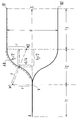
- the figure shows a simple optical branching with an incoming optical waveguide A, which branches at a point V into two outgoing waveguides B1 and B2.
- the two outgoing waveguides have a distance d from one another in their straight parts and run symmetrically with respect to an axis S which runs in the direction of the extension of the incoming waveguide A.
- the incoming waveguide A contributes the amount l1, the area of the curved sections of the outgoing waveguides B1 and B2 the amount l2 and the area of the straight sections of the outgoing waveguide the amount l3.
- Optically active areas AB of the simple branching shown are formed by the curved sections of the outgoing waveguides B1 and B2.
- the length l 2 of the region of the branching which contains the curved waveguide parts can be designed to be less than 130 ⁇ m, which is a considerable shortening compared to curved regions formed from passive waveguides , which are usually> 2 mm long. In addition to this shortening, there is the saving in length, which occurs because optically active, straight waveguide pieces are no longer required. This length saving is again approx. 250 ⁇ m per branching step.
- the active and passive waveguide regions can be produced in a single coating process by using coating methods which allow layers of different thicknesses to be grown in locally delimited regions.
- Scattering losses in the curved active waveguide areas are reduced by making the waveguides wider there than in straight waveguide areas.
Abstract
Description
Die Erfindung betrifft einen optischen Raumschalter gemäß dem Oberbegriff des Patentanspruchs 1.The invention relates to an optical space switch according to the preamble of patent claim 1.
Optische Raumschalter werden benötigt, wenn Licht vorgegebener Wellenlänge oder aus einer Überlagerung von Licht mehrerer Wellenlängen bestehendes Licht von einem einzelnen, ankommenden Wellenleiter selektiv auf einen oder auf eine Auswahl aus einer Vielzahl von abgehenden Wellenleitern überzuleiten ist. Den Verzweigungungsarmen einfacher Wellenleiterverzweigungen werden hierzu steuerbare, aktive Wellenleiterbereiche angefügt und die so entstehenden, steuerbaren Verzweigungen dann kaskadenartig hintereinandergeschaltet. Jede Verzweigung wird elektrisch so angesteuert, daß das in den jeweils gewünschten Verzweigungsarm eingestrahlte Licht verstärkt, das in den anderen Verzweigungsarm eingestrahlte Licht dagegen absorbiert oder zumindest abgeschwächt wird, die Verzweigung somit als optischer Wechselschalter arbeitet. Eine Kaskade derartiger Verzweigungen kann auch als optischer Verteiler arbeiten, wenn Licht in mehreren parallelen Verzweigungsarmen verstärkt wird.Optical space switches are required when light of a predetermined wavelength or light consisting of a superimposition of light of several wavelengths is to be selectively transferred from a single incoming waveguide to one or to a selection from a multiplicity of outgoing waveguides. For this purpose, controllable, active waveguide regions are added to the branching arms of simple waveguide branches, and the controllable branches thus created are then cascaded in series. Each branch is controlled electrically so that the light radiated into the desired branch arm is amplified, but the light radiated into the other branch arm is absorbed or at least weakened, so that the branch operates as an optical changeover switch. A cascade of such branches can also function as an optical distributor if light is amplified in several parallel branch arms.
Ein kaskadierter derartiger Raumschalter ist z.B. in der DE 43 04 993 A1 beschrieben. Die gesteuerten aktiven Bereiche sind dort als gerade Wellenleiterstücke ausgebildet (Fig. 1 u. 2) und durch gerade, oder, wo dies notwendig ist, durch gekrümmte passive Wellenleiterbereiche miteinander verbunden. Auch die in der o.g. DE 43 04 993 A1, in Spalte 1, Abs. 1 und Abs. 2 zitierten Druckschriften zeigen nur optische Schalter mit geraden optisch aktiven Wellenleiterbereichen.A cascaded room switch of this type is e.g. described in DE 43 04 993 A1. The controlled active areas are formed there as straight waveguide pieces (FIGS. 1 and 2) and are connected to one another by straight or, where necessary, by curved passive waveguide areas. Also those in the above Publications cited in column 1, paragraph 1 and paragraph 2 of DE 43 04 993 A1 only show optical switches with straight optically active waveguide regions.
Sind eine Vielzahl optischer Verzweigungen in einem optischen Raumschalter zu integrieren, so macht sich die Tatsache, daß jeder Verzweigung mindestens zwei gerade, aktive Wellenleiterbereiche hinzugefügt werden müssen, im Hinblick auf die Baulänge der gesamten hochintegrierten Schaltung nachteilig bemerkbar: Da die Substratgröße begrenzt ist, können auf einem Substrat nicht beliebig viele Verzweigungen untergebracht werden und es müssen aufwendige Glasfaserverbindungen zwischen mehreren, auf getrennten Substraten befindlichen integrierten Teilschaltungen hergestellt werden.If a large number of optical branches are to be integrated in an optical space switch, the fact that at least two straight, active waveguide regions have to be added to each branch has a disadvantageous effect with regard to the overall length of the entire highly integrated circuit: since the substrate size is limited, not any number of branches can be accommodated on a substrate and complex glass fiber connections have to be made between several integrated subcircuits located on separate substrates.
Es ist deshalb Aufgabe der Erfindung, die Baulänge der steuerbaren Verzweigungen zu verkürzen und damit einen höheren Integrationsgrad bei kaskadierten optischen Raumschaltern zu erreichen.It is therefore an object of the invention to shorten the overall length of the controllable branches and thus to achieve a higher degree of integration in cascaded optical space switches.
Diese Aufgabe wird durch die Merkmale des Patentanspruchs 1 gelöst.This object is achieved by the features of patent claim 1.
Durch die Verlagerung der optisch aktiven Bereiche in die ohnehin notwendigen gekrümmten Teile der Wellenleiter werden besondere gerade, aktive Wellenleiterstücke überflüssig. Außerdem lassen sich gekrümmte aktive Bereiche stärker krümmen und damit kürzer ausbilden als entsprechende passive Wellenleiter, um dieselbe Distanz der abgehenden Wellenleiter voneinander zu erreichen.By shifting the optically active areas into the curved parts of the waveguide that are necessary anyway, special straight, active waveguide pieces are superfluous. In addition, curved active areas can be curved more and are therefore shorter than corresponding passive waveguides in order to achieve the same distance of the outgoing waveguides from one another.
Gekrümmte aktive Welenleiterbereiche sind zwar z.B. im Zusammenhang mit sogenannten Y-Lasern bereits bekannt (siehe z.B. Aufsatz von O. Hildebrand et al in "Journal of Lightwave Technology", Vol. 11, No. 12, December 1993, Seiten 2066 bis 2072, insbesondere Absatz VII auf Seite 2071), sie sind dort jedoch nicht, wie für die Erfindung notwendig, den einzelnen Verzweigungsarmen zugeordnet, sondern gehören einem die eigentliche Verzweigung sowie Teile der an diese anschließenden Wellenleiter umfassenden, zentralen Bereich an. Wird ein Y-Laser als optischer Raumschalter eingesetzt, müssen zur separaten Ansteuerung der Verzweigungsarme deshalb die an den zentralen Bereich anschließenden, aktiven Armsegmente verwendet werden. Diese können somit nicht zur Verkürzung des Raumschalters eingespart werden.Curved active welder leader areas are e.g. already known in connection with so-called Y lasers (see, for example, article by O. Hildebrand et al in "Journal of Lightwave Technology", Vol. 11, No. 12, December 1993, pages 2066 to 2072, in particular paragraph VII on page 2071) However, they are not assigned to the individual branching arms as is necessary for the invention, but rather belong to the actual branching as well as parts of the central area surrounding the waveguide. If a Y laser is used as an optical room switch, the active arm segments adjoining the central area must therefore be used to separately control the branch arms. This means that they cannot be saved to shorten the room switch.
Bei dem optischen Raumschalter nach der Erfindung können die einzelnen Verzweigungen dagegen sehr viel kürzer ausgeführt werden, was bewirkt, daß ein Substrat wesentlich mehr optische Verzweigungen aufnehmen kann, als bei Ausbildung der aktiven Bereiche als gerade Wellenleiterstücke.In the optical space switch according to the invention, however, the individual branches can be made much shorter, which means that a substrate can accommodate significantly more optical branches than when the active areas are formed as straight waveguide pieces.
Ausgestaltungen des optischen Raumschalters nach der Erfindung sind in den Unteransprüchen angegeben.Embodiments of the optical space switch according to the invention are specified in the subclaims.
So enthält Anspruch 2 eine Vorschrift für eine einen hohen Integrationsgrad zulassende, vorteilhafte Dimensionierung der gekrümmten aktiven Wellenleiterbereiche.Claim 2 thus contains a regulation for an advantageous dimensioning of the curved active waveguide regions which permits a high degree of integration.
Anspruch 3 betrifft eine Maßnahme, die Streuungsverluste des Lichtes, die infolge der Krümmungen in den gekrümmten Wellenleiterbereichen auftreten, reduziert.Claim 3 relates to a measure that reduces scattering losses of light that occur as a result of the curvatures in the curved waveguide regions.
Aufgrund einer Figur soll nun ein Ausführungsbeispiel für den optischen Raumschalter nach der Erfindung beschrieben werden.An embodiment of the optical space switch according to the invention will now be described on the basis of a figure.
Die Figur zeigt eine einfache optische Verzweigung mit einem ankommenden optischen Wellenleiter A, der sich an einem Punkt V in zwei abgehende Wellenleiter B1 und B2 verzweigt. Die beiden abgehenden Wellenleiter haben in ihren geraden Teilen einen Abstand d voneinander und verlaufen symmetrisch in Bezug auf eine Achse S, die in Richtung der Verlängerung des ankommenden Wellenleiters A verläuft. Zur Gesamtlänge der Verzweigung trägt der ankommende Wellenleiter A den Betrag l₁, der Bereich der gekrümmten Teilstücke der abgehenden Wellenleiter B₁ und B₂ den Betrag l₂ und der Bereich der geraden Teilstücke der abgehenden Wellenleiter den Betrag l₃ bei. Optisch aktive Bereiche AB der dargestellten einfachen Verzweigung werden von den gekrümmten Teilstücken der abgehenden Wellenleiter B1 und B2 gebildet. Sie sind voneinander getrennt ansteuerbar und setzen sich aus je zwei Kreisbogenstücken zusammen, die jeweils zu Sektoren von Kreisen um einen Mittelpunkt M1 und einen Mittelpunkt M2 gehören. Wird der Radius r dieser Kreise z.B. zu r≧d/4 gewählt, dann nehmen die Kreissektoren einen Winkel von ≦ 90 Grad an. Wird im Extremfalle ![]()
![]()
![]()
![]()
Wird ein Abstand von d = 170 bis 260 µm als möglicher Wert für nebeneinanderliegende Faserkopplungen eingesetzt, so kann die Längenerstreckung l₂ des die gekrümmten Wellenleiterteile enthaltenden Bereichs der Verzweigung kleiner als 130 µm ausgelegt werden, was eine erhebliche Verkürzung gegenüber aus passiven Wellenleitern gebildeten, gekrümmten Bereichen, die in der Regel >2 mm lang sind, bedeutet. Zu dieser Verkürzung tritt noch die Längeneinsparung, die dadurch eintritt, daß keine optisch aktiven, geraden Wellenleiterstücke mehr benötigt werden. Diese Längeneinsparung beträgt pro Verzweigungsstufe nochmals ca. 250 µm.If a distance of d = 170 to 260 µm is used as a possible value for adjacent fiber couplings, the length l 2 of the region of the branching which contains the curved waveguide parts can be designed to be less than 130 µm, which is a considerable shortening compared to curved regions formed from passive waveguides , which are usually> 2 mm long. In addition to this shortening, there is the saving in length, which occurs because optically active, straight waveguide pieces are no longer required. This length saving is again approx. 250 µm per branching step.
Die aktiven und passiven Wellenleiterbereiche können, wie in der eingangs genannten Patentanmeldung beschrieben, in einem einzigen Beschichtungsprozeß hergestellt werden, indem Beschichtungsverfahren verwendet werden, die das Aufwachsen unterschiedlich dicker Schichten in lokal abgegrenzten Bereichen zulassen.As described in the patent application mentioned at the outset, the active and passive waveguide regions can be produced in a single coating process by using coating methods which allow layers of different thicknesses to be grown in locally delimited regions.
Streuungsverluste in den gekrümmten aktiven Wellenleiterbereichen werden dadurch reduziert, daß die Wellenleiter dort breiter ausgebildet werden als in geraden Wellenleiterbereichen.Scattering losses in the curved active waveguide areas are reduced by making the waveguides wider there than in straight waveguide areas.
Claims (3)
dadurch gekennzeichnet, daß voneinander unabhängig steuerbare optisch aktive Wellenleiterbereiche (AB) in Krümmungen der Wellenleiter ausgebildet sind.Optical space switch with interconnected, branched or unbranched, independently controllable light-amplifying or independently controllable light-absorbing (optically active) or non-amplified (passive) waveguide areas arranged on the same substrate
characterized in that independently controllable optically active waveguide regions (AB) are formed in curvatures of the waveguides.
Applications Claiming Priority (2)
| Application Number | Priority Date | Filing Date | Title |
|---|---|---|---|
| DE4445848 | 1994-12-22 | ||
| DE19944445848 DE4445848A1 (en) | 1994-12-22 | 1994-12-22 | Optical room switch with short overall length |
Publications (2)
| Publication Number | Publication Date |
|---|---|
| EP0718668A2 true EP0718668A2 (en) | 1996-06-26 |
| EP0718668A3 EP0718668A3 (en) | 1996-12-18 |
Family
ID=6536621
Family Applications (1)
| Application Number | Title | Priority Date | Filing Date |
|---|---|---|---|
| EP95119685A Withdrawn EP0718668A3 (en) | 1994-12-22 | 1995-12-14 | Short length optical space switch |
Country Status (2)
| Country | Link |
|---|---|
| EP (1) | EP0718668A3 (en) |
| DE (1) | DE4445848A1 (en) |
Cited By (1)
| Publication number | Priority date | Publication date | Assignee | Title |
|---|---|---|---|---|
| US6512860B2 (en) | 2000-08-18 | 2003-01-28 | Danmarks Tekniske Universitet | Bent electro-absorption modulator |
Families Citing this family (1)
| Publication number | Priority date | Publication date | Assignee | Title |
|---|---|---|---|---|
| DE19952216B4 (en) * | 1999-10-29 | 2009-04-02 | Carl Zeiss Meditec Ag | Arrangement for power regulation and monitoring of radiation transmitted through one or more optical fiber (s) |
Citations (4)
| Publication number | Priority date | Publication date | Assignee | Title |
|---|---|---|---|---|
| JPS5897028A (en) * | 1981-12-04 | 1983-06-09 | Oki Electric Ind Co Ltd | Optical waveguide switch |
| JPS6191623A (en) * | 1984-10-12 | 1986-05-09 | Nippon Telegr & Teleph Corp <Ntt> | Optical switch element |
| EP0444721A1 (en) * | 1990-01-29 | 1991-09-04 | Koninklijke KPN N.V. | Integrated optical polarisation splitter |
| DE4304993A1 (en) * | 1993-02-18 | 1994-08-25 | Sel Alcatel Ag | Process for producing a cascaded optical room switch and cascaded optical room switch produced by this process |
-
1994
- 1994-12-22 DE DE19944445848 patent/DE4445848A1/en not_active Withdrawn
-
1995
- 1995-12-14 EP EP95119685A patent/EP0718668A3/en not_active Withdrawn
Patent Citations (4)
| Publication number | Priority date | Publication date | Assignee | Title |
|---|---|---|---|---|
| JPS5897028A (en) * | 1981-12-04 | 1983-06-09 | Oki Electric Ind Co Ltd | Optical waveguide switch |
| JPS6191623A (en) * | 1984-10-12 | 1986-05-09 | Nippon Telegr & Teleph Corp <Ntt> | Optical switch element |
| EP0444721A1 (en) * | 1990-01-29 | 1991-09-04 | Koninklijke KPN N.V. | Integrated optical polarisation splitter |
| DE4304993A1 (en) * | 1993-02-18 | 1994-08-25 | Sel Alcatel Ag | Process for producing a cascaded optical room switch and cascaded optical room switch produced by this process |
Non-Patent Citations (3)
| Title |
|---|
| MARCATILI E A J: "Bends in Optical Dielectric Guides", BELL SYSTEM TECHNICAL JOURNAL, NEW YORK, September 1969, Band 48, Nr. 7, Seiten 2103 - 2132 * |
| PATENT ABSTRACTS OF JAPAN Bd. 007, Nr. 198 (P-220) 02 September 1983 & JP 58 097 028 A (OKI DENKI KOGYO KK) 09 Juni 1983 * |
| PATENT ABSTRACTS OF JAPAN Bd. 010, Nr. 266 (P-496) 11 September 1986 & JP 61 091 623 A (NIPPON TELEGR. & TELEPHON. CORP.) 09 Mai 1986 * |
Cited By (1)
| Publication number | Priority date | Publication date | Assignee | Title |
|---|---|---|---|---|
| US6512860B2 (en) | 2000-08-18 | 2003-01-28 | Danmarks Tekniske Universitet | Bent electro-absorption modulator |
Also Published As
| Publication number | Publication date |
|---|---|
| DE4445848A1 (en) | 1996-06-27 |
| EP0718668A3 (en) | 1996-12-18 |
Similar Documents
| Publication | Publication Date | Title |
|---|---|---|
| EP0863588B1 (en) | Laseroptics and laserdiode | |
| DE69917007T2 (en) | WAVELENGTH MULTIPLEXER / DEMULTILEXER OPTICAL DEVICE | |
| DE60320330T2 (en) | An optical waveguide, an optical device and an optical switch | |
| EP0037006B1 (en) | Optical star coupler with planar mixer element | |
| DE3309349A1 (en) | WAVELENGTH MULTIPLEXER OR DEMULTIPLEXER | |
| EP0788673A1 (en) | Arrangement for guiding and shaping beams from a rectilinear laser diode array | |
| EP0560412A2 (en) | Arrangement of optical-integrated spectrometer and method for making the same | |
| EP0629297A1 (en) | Integrated optical component. | |
| EP0476384A1 (en) | Optical grating with several end-areas arranged side by side for output of optical waveguides | |
| DE2910291A1 (en) | COMPONENT WITH OPTICAL FOCUS | |
| DE602004000098T2 (en) | Optical waveguide arrangement with reduced crossover losses | |
| DE60122247T2 (en) | Optical Multiplexer / Demultiplexer | |
| EP1070271B1 (en) | Arrangement for spatial separation and/or convergence of optical wavelength channels | |
| DE2905916A1 (en) | FIBER OPTICAL TRANSMISSION DEVICE | |
| DE60307610T2 (en) | OPTICAL COUPLER | |
| EP0831343A2 (en) | Optical waveguide and process for its manufacture | |
| DE3829540C2 (en) | Bent waveguide for an integrated optical circuit | |
| EP0718668A2 (en) | Short length optical space switch | |
| WO2016050898A1 (en) | Optical waveguide | |
| EP1076252A1 (en) | Adjusted integrated optical multiple beam interferometer | |
| EP0903823B1 (en) | Laser element incorporating a laser array and method of fabrication | |
| EP0822424B1 (en) | Optical branching element | |
| DE2722028A1 (en) | CORRECTIVE DEVICE FOR SPREADING BEAMS | |
| DE69737491T2 (en) | Integrated optical device with active and passive waveguide regions | |
| DE10054370A1 (en) | Optical signal distributor element for optical fibre network has light deflected between light conducting core regions contained in different parallel layers |
Legal Events
| Date | Code | Title | Description |
|---|---|---|---|
| PUAI | Public reference made under article 153(3) epc to a published international application that has entered the european phase |
Free format text: ORIGINAL CODE: 0009012 |
|
| AK | Designated contracting states |
Kind code of ref document: A2 Designated state(s): DE ES FR GB IT |
|
| PUAL | Search report despatched |
Free format text: ORIGINAL CODE: 0009013 |
|
| AK | Designated contracting states |
Kind code of ref document: A3 Designated state(s): DE ES FR GB IT |
|
| 17P | Request for examination filed |
Effective date: 19970207 |
|
| 17Q | First examination report despatched |
Effective date: 20020529 |
|
| STAA | Information on the status of an ep patent application or granted ep patent |
Free format text: STATUS: THE APPLICATION IS DEEMED TO BE WITHDRAWN |
|
| 18D | Application deemed to be withdrawn |
Effective date: 20021009 |