EP0718656A1 - Transmission type confocal laser microscope - Google Patents
Transmission type confocal laser microscope Download PDFInfo
- Publication number
- EP0718656A1 EP0718656A1 EP94309817A EP94309817A EP0718656A1 EP 0718656 A1 EP0718656 A1 EP 0718656A1 EP 94309817 A EP94309817 A EP 94309817A EP 94309817 A EP94309817 A EP 94309817A EP 0718656 A1 EP0718656 A1 EP 0718656A1
- Authority
- EP
- European Patent Office
- Prior art keywords
- objective lens
- optical path
- transmission side
- side objective
- light
- Prior art date
- Legal status (The legal status is an assumption and is not a legal conclusion. Google has not performed a legal analysis and makes no representation as to the accuracy of the status listed.)
- Granted
Links
Images

Classifications
-
- G—PHYSICS
- G02—OPTICS
- G02B—OPTICAL ELEMENTS, SYSTEMS OR APPARATUS
- G02B21/00—Microscopes
- G02B21/0004—Microscopes specially adapted for specific applications
- G02B21/002—Scanning microscopes
- G02B21/0024—Confocal scanning microscopes (CSOMs) or confocal "macroscopes"; Accessories which are not restricted to use with CSOMs, e.g. sample holders
- G02B21/0036—Scanning details, e.g. scanning stages
- G02B21/0048—Scanning details, e.g. scanning stages scanning mirrors, e.g. rotating or galvanomirrors, MEMS mirrors
-
- G—PHYSICS
- G02—OPTICS
- G02B—OPTICAL ELEMENTS, SYSTEMS OR APPARATUS
- G02B21/00—Microscopes
- G02B21/0004—Microscopes specially adapted for specific applications
- G02B21/002—Scanning microscopes
- G02B21/0024—Confocal scanning microscopes (CSOMs) or confocal "macroscopes"; Accessories which are not restricted to use with CSOMs, e.g. sample holders
- G02B21/0052—Optical details of the image generation
Landscapes
- Physics & Mathematics (AREA)
- Chemical & Material Sciences (AREA)
- Analytical Chemistry (AREA)
- General Physics & Mathematics (AREA)
- Optics & Photonics (AREA)
- Microscoopes, Condenser (AREA)
Abstract
Description
- The present invention relates to a laser microscope and in particular to a transmission type confocal laser microscope which forms an image of a transmitted light from a specimen.
- Confocal laser microscopes generally scan a laser light spot which is focused to a size of about 1 micron along a specimen. A light having a brightness or darkness in individual positions (points) is detected by a photoelectric transducing sensor. A converted electric signal is integrated for displaying it on an large screen of a monitor display. This type of confocal laser microscopes have an advantage in that defocussed light or spurious light can be eliminated since the specimen is always illuminated in only individual desired positions so that unnecessary spurious light is not mixed with a desired light and since light is received through a pinhole having a size which is substantially equal to that of the specimen scanning spot light in a position which is in a conjugate position for specimen plane. Accordingly, the confocal laser microscopes provide a higher resolution and contrast in comparison with conventional optical microscopes even if same objective lens is used.
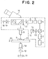
- The confocal laser microscopes are classified into two types, i.e. a reflection type laser microscope in which light reflected from a specimen is imaged and a transmission type laser microscope in which light transmitted through a specimen is imaged. Typical structure of the conventional transmission type confocal laser microscope is schematically shown in Fig. 2. This type of laser microscope emits a polarized laser light from a light source 1. The flux of the light is enlarged by an expander 2a and is transmitted through a polarized beam splitter 3 and is scanned in a transverse (X) direction and in a vertical (Y) direction by means of Galvano-
mirrors 4 and 5 which are Galvanometers with mirrors. The light is once converged by arelay lens 6 in a position of a field stop (corresponding to an imaging point of an objective lens). The light is transmitted through an illumination sideobjective lens 8 and is scanned on and along aspecimen 9 as a spot. - The laser light which has been transmitted through the
specimen 9 is transmitted through a transmission sideobjective lens 10 which is optically equivalent to the illumination sideobjective lens 8 and is imaged on the surface of aconcave mirror 11. Theconcave mirror 11 has a reflective mirror surface which is spherical around the pupil position of the transmission sideobjective lens 10. The light flux which is reflected on themirror 11 is returned via the same optical path. A 1/4λwave length plate 12 which changes the polarization direction by 45° is provided between theconcave mirror 11 and the transmission sideobjective lens 10. The reflected laser light is incident upon the above mentioned polarized beam splitter 3. Only the light which was transmitted twice through the 1/4λwave length plate 12 is reflected and is bent in a normal direction by the splitter 3. The split and bent light is transmitted through acondenser lens 13 and a pin-hole 14 is incident upon a specimensignal detecting sensor 15 comprising light receiving elements. The detected signal is photoelectrically converged into an electric signal and is then fed to a memory. - In the drawings,
reference numeral 16 denotes a binocular head; 17 an optical path switch which is used when the binocular head is used; 18 a light source for vertical overhead illumination; and 19 a relay lens for thelight source 18. - In order to use the conventional type confocal laser microscope, a
preparation 21 is firstly placed on aspecimen stage 20 as shown in Fig. 3. Light is focussed on the surface of thespecimen 9 by the illumination sideobjective lens 8. It is necessary to shift or displace the transmission sideobjective lens 10 by a slight length ( L) each time when the transmission sideobjective lens 10 is adjusted since the level of the specimen is different depending upon the thickness of thepreparation 21. The thickness of the glass portion of the preparation usually has variations within about ±0.3 mm among the different preparations. - Accordingly, the
optical path changer 17 is conventionally switched to move toward an optical microscope unit which is on the side of thebinocular head 16. Light from thelight source 18 for vertical overhead illumination is focussed on the specimen by adjusting the illumination sideobjective lens 8. The image of the light reflected from theconcave mirror 11 is superposed upon the image of the light reflected from the specimen by adjusting the transmission sideobjective lens 10. Thereafter, theoptical path switch 17 is switched to the laser light side. - Alternatively, the transmission side
objective lens 10 is preliminarily adjusted to a position suitable for the preparation having a standard thickness. Focussing is achieved by means of the optical microscope unit including the illumination sideobjective lens 8. Light is then switched to laser light. The transmission sideobjective lens 10 is finely adjusted to provide the highest resolution while observing the image on the synthetic monitor. - Such conventional systems have a problem that focussing adjustment by means of the transmission side
objective lens 10 is troublesome and focussing accuracy is low, resulting in difficulty to provide a high resolution. - The present invention was made to overcome the above mentioned problem.
- It is an object of the present invention to provide a transmission type confocal laser microscope in which adjustment of the transmission side objective lens for focussing can be achieved easily, accurately and stably.
- In an aspect of the present invention, there is provided a transmission type confocal laser microscope in which a laser spot light which is condensed through an illumination side objective lens is incident and scanned on a specimen from a face side thereof, a light which is transmitted through the specimen to the reverse side thereof and is reflected on a concave mirror located on a focal point of a transmission side objective lens which is optically equivalent to the illumination side objective lens and is returned along the same optical path so that returned light is received by an photoreceiving element, characterized in that it further includes an optical path switch behind the transmission side objective lens for switching between the optical path to said concave mirror and another optical path different from the former optical path; and a target which is illuminated with a light source for adjusting the transmission side objective lens, said target being located on said another optical path in a position optically equal to said concave mirror.
- Said objective lens may comprise an objective lens unit which is movable in a direction of an optical axis and a fixed relay lens unit, wherein movement of the objective lens unit for focus adjustment will not cause the optical path after the relay lens unit to be changed.
- The optical path on which the transmission side objective lens and fixed relay lens are located may be normal to the optical path on which the optical path switch, the concave mirror and the target are located.
- The optical path switch may comprise a pair of reflective prisms which are movable with respect to the optical axis of the transmission side objective lens and the relay lens.
- The optical path switch may comprise a reflective mirror which is rotatable around the optical axis of the transmission side objective lens and the relay lens.
- In the transmission type confocal laser microscope, adjustment of the illumination side objective lens for focussing is achieved by moving the specimen stage while the specimen is illuminated with the optical microscope unit which is similar to the prior art. The transmission side objective lens is adjusted for focussing as follows: The optical path from the transmission side objective lens to the concave mirror is switched to the target side. The specimen is illuminated with a light source for focus adjustment. Focussing on the target is achieved by adjusting the transmission side objective lens while observing the specimen through the optical microscope unit. Both objective lenses can be positioned in complete confocal points.
- Since the transmission side objective lens comprises the movable objective lens unit and the stationary relay lens unit, focus adjustment is achieved by moving only the objective lens unit. Accordingly, the concave mirror, the optical path switch and the target which are in the rear of the relay lens can be incorporated in a stable fixed block.
-
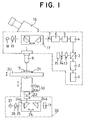
- Fig. 1 is a schematic view showing one embodiment of the present invention;
- Fig. 2 is a schematic view showing a prior art; and
- Fig. 3(A) and 3(B) are views for comparing the shifts of the objective lens units of prior art transmission type confocal laser microscopes with each other.
- An embodiment of the present invention will now be explained with reference to Fig. 1. Like parts corresponding to those of the above-mentioned prior art are represented by like reference numerals throughout the drawings. Detailed description of like parts will be omitted.
- The embodiment is identical with the prior art of Fig. 2 in structure of the optical system from the light source 1 for emitting polarized laser light to the
specimen 9 and the optical microscope unit from the light source for vertical overhead illumination and thebinocular head 17 to thespecimen 9 excepting the feature which will be described hereinafter. Accordingly, description of them will be omitted. - In the embodiment, the transmission side
objective lens 10 below thespecimen stage 20 comprises a relay lens unit 10b, the position of which is fixed and an objective lens unit 10b which is incorporated in such a manner that it is movable relative to the relay lens 10b. Theobjective lens unit 10a comprises a lens having characteristics equal to those of an objective lens having an infinitive length and the objective lens unit comprises a lens having characteristics equal to those of an imaging lens similar to a telescopic objective lens. The performance of the optical system behind the relay lens unit 10b is not changed even if the spacing between theobjective lens unit 10a and the relay lens unit 10b is changed. - An
optical path switch 24 is provided in the rear of the 1/4λwave length plate 12 in an optical path in the rear of the transmission sideobjective lens 10. Theoptical switch 24 comprises totalreflective prisms reflective prism 24a is adapted to bend the optical path toward theconcave mirror 11 in a normal direction. The other totalreflective prism 24b is adapted to bend the optical path toward afocus target 25. - The
concave mirror 11 has a concave surface in a position where the laser light reflected from theprism 24a is imaged by the transmission sideobjective lens 10. The concave surface has a center which is located in the pupil position of theobjective lens 10. - A
target 25 comprises, for example, a circular ring and is positioned in an imaging position of the transmission side objective similarly to the reflective surface of theconcave mirror 11. Thetarget 25 is illuminated with alight source 27 via arelay lens 26. The components in the rear of therelay lens 26 are secured within a fixingblock 30. Theprisms - The thus formed laser microscope emits a polarized laser light from the light source 1 similarly to the conventional microscope as shown in Fig. 1. The emitted light is transmitted through the
expander 2, the polarized beam splitter 3, the Galvano-mirrors 4,5, therelay lens 6 and the field and illumination sideobjective lens 8. The laser light is focused upon thespecimen 9 as a spot and is scanned therealong. The light which has been transmitted through thespecimen 9 is transmitted through the transmission sideobjective lens 10 and the light is bent by thereflective prism 24a and is reflected on theconcave mirror 11. The reflected light is reversed along the same optical path to reach the polarized beam splitter 3. Only the reflected light is reflected and is bent in a normal direction and is transmitted through the condensinglens 13 and is detected by the specimen signal detecting sensor comprising photoreceiving elements. - Adjustment of illumination side objective lens for focussing is conducted by lowering and elevating the
specimen platen 20 while observing through thebinocular head 17, thespecimen 9 which is illuminated by a vertical overhead illumination light source as shown in Fig. 1. - Adjustment of the transmission side
objective lens 10 for focussing on thetarget 25 is conducted by switching the optical path switch 24 into the optical path on the side of thetarget 25, turning the light source on and moving only theobjective lens unit 10a while viewing thebinocular head 17 without using thelight source 18. - After both
objective lenses lower switch 24 is actuated to switch the optical path into the side of theconcave mirror 11. The above-mentioned observation with laser light is conducted. - Alternatively, adjustment of the illumination side
objective lens 8 for focussing on the specimen may be conducted while illuminating with the light source in stead of the vertical overheadillumination light source 18. - In accordance with the present invention, the focussing target is positioned in a position which is optically equal to the concave mirror in an optical path behind the transmission side objective lens. Focussing adjustment is conducted while viewing through the optical microscope unit. Thus, adjustment of the transmission side objective lens for focussing can be achieved at ease, fast and higher accuracy.
- The transmission side objective lens comprises the objective lens unit and the relay lens unit. Movement of only the objective lens unit will not change the optical path after the relay lens unit.
- Components of the optical system including the relay lens unit, subsequent concave mirror and components existing up to the target can be incorporated within a common fixed block. Accordingly, a high precision transmission type confocal laser microscope in which the optical axes before and after the specimen stage are completely aligned with each other.
Claims (5)
- A transmission type confocal laser microscope in which a laser spot light which is condensed through an illumination side objective lens is incident and scanned on a specimen from a face side thereof, a light which is transmitted through the specimen to the reverse side thereof and is reflected on a concave mirror located on a focal point of a transmission side objective lens which is optically equivalent to the illumination side objective lens and is returned along the same optical path so that returned light is received by an photoreceiving element, characterized in that it further includes an optical path switch behind the transmission side objective lens for switching between the optical path to said concave mirror and another optical path different from the former optical path; and a target which is illuminated with a light source for adjusting the transmission side objective lens, said target being located on said another optical path in a position optically equal to said concave mirror.
- A transmission type confocal laser microscope as defined in Claim 1 in which said transmission side objective lens comprises an objective lens unit which is movable in a direction of an optical axis and a fixed relay lens unit, wherein movement of the objective lens unit for focus adjustment will not cause the optical path after the relay lens unit to be changed.
- A transmission type confocal laser microscope as defined in Claim 1 or 2 in which the optical path on which the transmission side objective lens and fixed relay lens are located is normal to the optical path on which the optical path switch, the concave mirror and the target are located.
- A transmission type confocal laser microscope as defined in one of Claims 1 to 3 in which said optical path switch comprises a pair of reflective prisms which are movable with respect to the optical axis of the transmission side objective lens and the relay lens.
- A transmission type confocal laser microscope as defined in on of Claims 1 to 3 in which said optical path switch comprises a reflective mirror which is rotatable around the optical axis of the transmission side objective lens and the relay lens.
Priority Applications (2)
| Application Number | Priority Date | Filing Date | Title |
|---|---|---|---|
| EP19940309817 EP0718656B1 (en) | 1994-12-23 | 1994-12-23 | Transmission type confocal laser microscope |
| DE1994620569 DE69420569T2 (en) | 1994-12-23 | 1994-12-23 | Confocal transmitted light laser microscope |
Applications Claiming Priority (1)
| Application Number | Priority Date | Filing Date | Title |
|---|---|---|---|
| EP19940309817 EP0718656B1 (en) | 1994-12-23 | 1994-12-23 | Transmission type confocal laser microscope |
Publications (2)
| Publication Number | Publication Date |
|---|---|
| EP0718656A1 true EP0718656A1 (en) | 1996-06-26 |
| EP0718656B1 EP0718656B1 (en) | 1999-09-08 |
Family
ID=8217965
Family Applications (1)
| Application Number | Title | Priority Date | Filing Date |
|---|---|---|---|
| EP19940309817 Expired - Lifetime EP0718656B1 (en) | 1994-12-23 | 1994-12-23 | Transmission type confocal laser microscope |
Country Status (2)
| Country | Link |
|---|---|
| EP (1) | EP0718656B1 (en) |
| DE (1) | DE69420569T2 (en) |
Cited By (4)
| Publication number | Priority date | Publication date | Assignee | Title |
|---|---|---|---|---|
| DE19801139A1 (en) * | 1998-01-14 | 1999-07-15 | Rainer Dr Uhl | Point scanning luminescence microscope for investigating biological specimens using bifocal scanning |
| WO2000007056A1 (en) * | 1998-07-30 | 2000-02-10 | Carl Zeiss Jena Gmbh | Confocal theta microscope |
| EP1211542A2 (en) * | 2000-11-08 | 2002-06-05 | Leica Microsystems Heidelberg GmbH | System for visual and quantitative 3D-inspection of samples |
| WO2010048041A1 (en) * | 2008-10-22 | 2010-04-29 | Microbrightfield, Inc. | Movable objective lens assembly for an optical microscope and optical microscopes having such an assembly |
Families Citing this family (1)
| Publication number | Priority date | Publication date | Assignee | Title |
|---|---|---|---|---|
| DE102005003437B4 (en) * | 2004-02-11 | 2016-06-02 | Carl Zeiss Meditec Ag | Operating microscope with a rotatable beam switching device for a binocular observation beam path |
Citations (4)
| Publication number | Priority date | Publication date | Assignee | Title |
|---|---|---|---|---|
| DE3804642A1 (en) * | 1987-04-02 | 1988-10-20 | Jenoptik Jena Gmbh | Arrangement for avoiding the variable aperture aberration (spherical aberration) in scanning microscopes having z-scan |
| US5035476A (en) * | 1990-06-15 | 1991-07-30 | Hamamatsu Photonics K.K. | Confocal laser scanning transmission microscope |
| DE9310307U1 (en) * | 1992-07-24 | 1993-09-02 | Zeiss Carl Fa | Inverse laser scanning microscope |
| JPH05288992A (en) * | 1992-04-15 | 1993-11-05 | Laser Tec Kk | Transmission type microscope |
-
1994
- 1994-12-23 EP EP19940309817 patent/EP0718656B1/en not_active Expired - Lifetime
- 1994-12-23 DE DE1994620569 patent/DE69420569T2/en not_active Expired - Fee Related
Patent Citations (4)
| Publication number | Priority date | Publication date | Assignee | Title |
|---|---|---|---|---|
| DE3804642A1 (en) * | 1987-04-02 | 1988-10-20 | Jenoptik Jena Gmbh | Arrangement for avoiding the variable aperture aberration (spherical aberration) in scanning microscopes having z-scan |
| US5035476A (en) * | 1990-06-15 | 1991-07-30 | Hamamatsu Photonics K.K. | Confocal laser scanning transmission microscope |
| JPH05288992A (en) * | 1992-04-15 | 1993-11-05 | Laser Tec Kk | Transmission type microscope |
| DE9310307U1 (en) * | 1992-07-24 | 1993-09-02 | Zeiss Carl Fa | Inverse laser scanning microscope |
Non-Patent Citations (1)
| Title |
|---|
| PATENT ABSTRACTS OF JAPAN vol. 18, no. 78 (P - 1689) 8 February 1994 (1994-02-08) * |
Cited By (9)
| Publication number | Priority date | Publication date | Assignee | Title |
|---|---|---|---|---|
| DE19801139A1 (en) * | 1998-01-14 | 1999-07-15 | Rainer Dr Uhl | Point scanning luminescence microscope for investigating biological specimens using bifocal scanning |
| US6088097A (en) * | 1998-01-14 | 2000-07-11 | Uhl; Rainer | Point-scanning luminescent microscope |
| DE19801139B4 (en) * | 1998-01-14 | 2016-05-12 | Till Photonics Gmbh | Point Scanning Luminescence Microscope |
| WO2000007056A1 (en) * | 1998-07-30 | 2000-02-10 | Carl Zeiss Jena Gmbh | Confocal theta microscope |
| EP1211542A2 (en) * | 2000-11-08 | 2002-06-05 | Leica Microsystems Heidelberg GmbH | System for visual and quantitative 3D-inspection of samples |
| EP1211542A3 (en) * | 2000-11-08 | 2003-08-27 | Leica Microsystems Heidelberg GmbH | System for visual and quantitative 3D-inspection of samples |
| WO2010048041A1 (en) * | 2008-10-22 | 2010-04-29 | Microbrightfield, Inc. | Movable objective lens assembly for an optical microscope and optical microscopes having such an assembly |
| US8077386B2 (en) | 2008-10-22 | 2011-12-13 | Microbrightfield, Inc. | Movable objective lens assembly for an optical microscope and optical microscopes having such an assembly |
| US8270071B2 (en) | 2008-10-22 | 2012-09-18 | Microbrightfield, Inc. | Movable objective lens assembly for an optical microscope and optical microscopes having such an assembly |
Also Published As
| Publication number | Publication date |
|---|---|
| EP0718656B1 (en) | 1999-09-08 |
| DE69420569D1 (en) | 1999-10-14 |
| DE69420569T2 (en) | 2000-05-04 |
Similar Documents
| Publication | Publication Date | Title |
|---|---|---|
| US5506725A (en) | Transmission type confocal laser microscope | |
| US5737121A (en) | Real time scanning optical macroscope | |
| EP0746865B1 (en) | Fluorescence imaging system employing a macro scanning objective | |
| US5032720A (en) | Confocal imaging system | |
| US5225671A (en) | Confocal optical apparatus | |
| EP0418928B1 (en) | Scanning microscope and scanning mechanism for the same | |
| US7304281B2 (en) | Confocal laser scanning microscope | |
| US5260569A (en) | Scanning microscope and scanning mechanism | |
| US4893008A (en) | Scanning optical microscope | |
| US5932871A (en) | Microscope having a confocal point and a non-confocal point, and a confocal point detect method applied thereto | |
| EP1245986B1 (en) | Confocal microscope | |
| US7042638B2 (en) | Device for coupling light into a microscope | |
| US7554726B2 (en) | Objective for evanescent illumination and microscope | |
| WO1988007695A1 (en) | Scanning confocal optical microscope | |
| US5144477A (en) | Method of operating a scanning confocal imaging system | |
| WO1992002838A1 (en) | Confocal imaging system for microscopy | |
| KR19980071039A (en) | Optical microscope device | |
| EP0536273B1 (en) | Apparatus and method for transmitted-light and reflected-light imaging | |
| EP0718656B1 (en) | Transmission type confocal laser microscope | |
| JP4228125B2 (en) | microscope | |
| JP2576021B2 (en) | Transmission confocal laser microscope | |
| US4406526A (en) | Focusing of optical viewing apparatus | |
| GB2076176A (en) | Focusing Optical Apparatus | |
| JP2571859B2 (en) | Scanning optical microscope | |
| JPH02188711A (en) | Laser optical device |
Legal Events
| Date | Code | Title | Description |
|---|---|---|---|
| PUAI | Public reference made under article 153(3) epc to a published international application that has entered the european phase |
Free format text: ORIGINAL CODE: 0009012 |
|
| AK | Designated contracting states |
Kind code of ref document: A1 Designated state(s): DE FR GB |
|
| 17P | Request for examination filed |
Effective date: 19961129 |
|
| 17Q | First examination report despatched |
Effective date: 19970305 |
|
| GRAG | Despatch of communication of intention to grant |
Free format text: ORIGINAL CODE: EPIDOS AGRA |
|
| GRAG | Despatch of communication of intention to grant |
Free format text: ORIGINAL CODE: EPIDOS AGRA |
|
| GRAH | Despatch of communication of intention to grant a patent |
Free format text: ORIGINAL CODE: EPIDOS IGRA |
|
| GRAH | Despatch of communication of intention to grant a patent |
Free format text: ORIGINAL CODE: EPIDOS IGRA |
|
| GRAA | (expected) grant |
Free format text: ORIGINAL CODE: 0009210 |
|
| AK | Designated contracting states |
Kind code of ref document: B1 Designated state(s): DE FR GB |
|
| RIN1 | Information on inventor provided before grant (corrected) |
Inventor name: SUZUKI, SHOHI Inventor name: KOIKE, HIROSHI |
|
| REF | Corresponds to: |
Ref document number: 69420569 Country of ref document: DE Date of ref document: 19991014 |
|
| ET | Fr: translation filed | ||
| PLBE | No opposition filed within time limit |
Free format text: ORIGINAL CODE: 0009261 |
|
| STAA | Information on the status of an ep patent application or granted ep patent |
Free format text: STATUS: NO OPPOSITION FILED WITHIN TIME LIMIT |
|
| 26N | No opposition filed | ||
| REG | Reference to a national code |
Ref country code: GB Ref legal event code: IF02 |
|
| PGFP | Annual fee paid to national office [announced via postgrant information from national office to epo] |
Ref country code: GB Payment date: 20051208 Year of fee payment: 12 |
|
| PGFP | Annual fee paid to national office [announced via postgrant information from national office to epo] |
Ref country code: FR Payment date: 20051230 Year of fee payment: 12 |
|
| PGFP | Annual fee paid to national office [announced via postgrant information from national office to epo] |
Ref country code: DE Payment date: 20060216 Year of fee payment: 12 |
|
| PG25 | Lapsed in a contracting state [announced via postgrant information from national office to epo] |
Ref country code: DE Free format text: LAPSE BECAUSE OF NON-PAYMENT OF DUE FEES Effective date: 20070703 |
|
| GBPC | Gb: european patent ceased through non-payment of renewal fee |
Effective date: 20061223 |
|
| REG | Reference to a national code |
Ref country code: FR Ref legal event code: ST Effective date: 20070831 |
|
| PG25 | Lapsed in a contracting state [announced via postgrant information from national office to epo] |
Ref country code: GB Free format text: LAPSE BECAUSE OF NON-PAYMENT OF DUE FEES Effective date: 20061223 |
|
| PG25 | Lapsed in a contracting state [announced via postgrant information from national office to epo] |
Ref country code: FR Free format text: LAPSE BECAUSE OF NON-PAYMENT OF DUE FEES Effective date: 20070102 |