EP0713953B1 - Method of drilling and completing wells - Google Patents
Method of drilling and completing wells Download PDFInfo
- Publication number
- EP0713953B1 EP0713953B1 EP95118243A EP95118243A EP0713953B1 EP 0713953 B1 EP0713953 B1 EP 0713953B1 EP 95118243 A EP95118243 A EP 95118243A EP 95118243 A EP95118243 A EP 95118243A EP 0713953 B1 EP0713953 B1 EP 0713953B1
- Authority
- EP
- European Patent Office
- Prior art keywords
- string
- wellbore
- stationary
- bottomhole assembly
- specified
- Prior art date
- Legal status (The legal status is an assumption and is not a legal conclusion. Google has not performed a legal analysis and makes no representation as to the accuracy of the status listed.)
- Expired - Lifetime
Links
Images


Classifications
-
- E—FIXED CONSTRUCTIONS
- E21—EARTH DRILLING; MINING
- E21B—EARTH DRILLING, e.g. DEEP DRILLING; OBTAINING OIL, GAS, WATER, SOLUBLE OR MELTABLE MATERIALS OR A SLURRY OF MINERALS FROM WELLS
- E21B43/00—Methods or apparatus for obtaining oil, gas, water, soluble or meltable materials or a slurry of minerals from wells
- E21B43/11—Perforators; Permeators
-
- E—FIXED CONSTRUCTIONS
- E21—EARTH DRILLING; MINING
- E21B—EARTH DRILLING, e.g. DEEP DRILLING; OBTAINING OIL, GAS, WATER, SOLUBLE OR MELTABLE MATERIALS OR A SLURRY OF MINERALS FROM WELLS
- E21B23/00—Apparatus for displacing, setting, locking, releasing, or removing tools, packers or the like in the boreholes or wells
-
- E—FIXED CONSTRUCTIONS
- E21—EARTH DRILLING; MINING
- E21B—EARTH DRILLING, e.g. DEEP DRILLING; OBTAINING OIL, GAS, WATER, SOLUBLE OR MELTABLE MATERIALS OR A SLURRY OF MINERALS FROM WELLS
- E21B43/00—Methods or apparatus for obtaining oil, gas, water, soluble or meltable materials or a slurry of minerals from wells
- E21B43/02—Subsoil filtering
- E21B43/04—Gravelling of wells
- E21B43/045—Crossover tools
Definitions
- the present invention relates to drilling and completing of wells.
- the invention relates to drilling and completing of hydrocarbon wells.
- a method and device for perforating a wall of a well by use of a tool such as an explosive gun is known from U.S. 5,044,437.
- Said method includes the use of an intervention set.
- This set has a perforating tool associated with a measuring box such as a logging sonde and temperature and pressure sensors which is taken down into the well.
- the set is suspended by a linking cable on a support frame which can be locked inside and at the base of a tubing.
- the tubing is taken down to the intervention area and blocked by a packer.
- the support frame and the set are displaced by a control cable lowered down from the surface and the best places for carrying out shootings or perforations in the well are determined through measurements made by the measuring box. Sensors contained in the box allow an operator to check the results.
- the perforating tool for example, an explosive gun
- the support frame and the box are taken up in order to clear the inside of the tubing.
- one type of installation includes use of a fixed platform wherein the legs of the platform are rigid and embedded into the sea floor.
- the fixed platform has been a very popular type of structure; however, as the search for reserves continues, oil and gas companies find themselves searching in offshore locations were the water depths may be as deep as 1.829m (6,000').
- the BOP stack When the operator is converting from the drilling phase to the completion phase, the BOP stack must be changed out to accommodate the different outer diameter sized work string---from drill pipe to a production string. Furthermore, during the actual completion phase, the production tubing must be manipulated in order to perform the necessary functions such as perforating, circulating, gravel packing and testing. According to established safety procedures mandated by operator rules and government regulations, it is necessary to change out the BOP rams during certain phases. The changing out of BOP rams can be a costly and time consuming practice. Day rates for drill ships and semi-submersible ships can be quite expensive, and during the procedure for changing out the rams, no other substantive operations can be accomplish.
- the BOP In a typical offshore location, wherein the drilling rig is either a jack-up vessel or placed upon a fixed platform, the BOP is normally situated on the vessel or platform itself. Nevertheless, because of safety considerations and government regulations, the control of the well bore from blow-out is always of primary concern. Therefore, safety of the installation along with economically performing the operation has always been a need.
- this object is achieved by a method according to claim 1 and by an apparatus according to claim 3.
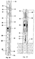
- Fig. 1 depicts a semi-submersible drilling vessel 2 that has contained thereon a drilling rig 4 .
- a sub-sea Blow-Out Preventor stack 8 is positioned on the ocean floor 10 , with a riser 12 linking the sub-sea BOP stack 8 and the drilling rig. Extending into the earth from the sub-sea stack 8 will be the well casings, including the conductor, surface, and intermediate 14, 16, and 18 , respectively.
- a stationary string 20 is positioned within the riser 12 and casing string 18.
- the casing strings will intersect various subterranean reservoirs 22 , some of which may contain hydrocarbons. As is shown in Fig. 1, a target reservoir 24 has yet to be drilled through.
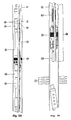
- a bottom hole assembly 30 is positioned within a casing string 32 .
- a stationary string 34 with an internal diameter 36 and an outer diameter 38 , which in this illustration may be a production string, but it should be understood that the string may be other types of conduit including drill pipe.
- the stationary string will have included a nipple profile means 40 for the setting of various devices, with the nipple means 40 having an internal profile 42 .
- the string 34 may also contain packer means 44 for sealingly engaging the inner diameter of the casing 32 so that when packer means 44 is set, an annulus between the string 34 and casing 32 is formed.
- the packer means 44 may be of the hydraulic and mechanical type and are commercially available from Baker Hughes Incorporated under the product name "SC" style packers.
- An upper annulus 46 would be formed from the packer means 44 to the surface, and a lower annulus 48 would be formed below the packer means 44.
- the string 34 may consist of a gravel pack extension section means 50 for the placement of a gravel slurry through the ports 52 in the lower annulus 48, as will be more fully explained later in the application.
- the gravel pack extension means 50 is commercially available from Baker Hughes Incorporated under the trade name "S-1" Gravel Pack Extension.
- the string 34 may also contain a mechanical release profile means 54 , which will have an internal profile 56 , for the placement of a mechanical setting & release tool, as will be described hereafter.
- the bottom hole assembly 30 will be attached to a release mechanism 58 that will contain collet members 60 that cooperate with the internal profile 42 of the nipple profile means 40.
- the release mechanism 58 may be attached to a section of blank pipe 62 , that in turn will be connected to means for preventing the flow of formation sand 64 .
- the preventing means 64 is a section of perforated pipe 66 that is surrounded by a wrapped wire mesh segment 68 .
- the bottom hole assembly 30 will also consist of a packer means 70 for sealingly engaging with the well casing 32.
- the packer means 70 shown is a mechanical packer, however, any type of packer, such as hydraulic or rotational, commercially available from Baker Hughes Incorporated under the product names Model "R", and "SC-LP" packer could be used.
- the assembly 30 will further contain perforating means 72 for perforating the casing 32 in a subterranean reservoir.
- the perforating means 72 is a tubing conveyed gun; however, any other perforating means well known in the art could have been used.
- the perforating means 72 will be attached to the packer means 70, and the remainder of the bottom hole assembly 30 through a mechanical gun release means 74 for mechanically releasing the guns after firing.
- the release means 74 may be mechanical, or hydraulic automatic gun release means. These release means 74 are also well know in the art, and are commercially available from Baker Hughes Incorporated under the product name Model "C" Auto Release Firing Head.
- the internal mechanism consist of a piston release means 76 that is hydraulically activated.
- either pressure activation and/or mechanical means can be used.
- the mechanical means 77 will be used which is commercially available from Baker Hughes Incorporated and referred to as the Mechanical Firing Head.
- the actual firing with the mechanical means is performed by dropping a metal bar or bars from the surface.
- FIGs. 3A-3B the stationary string 34 and the bottom hole assembly 30 is shown after having fired with the perforating means 72 creating a series of perforating tunnels 77 that extend through the casing and into the formation.
- the pressures created due to the firing of the guns will activate the release means 74, 76.
- the figure depicts the perforating guns having been fired, lowered, and thereafter having been dropped from the bottom hole assembly 30.
- a secondary string 84 which in the preferred embodiment is a coiled tubing string, is run into the well in the inner diameter 36 of the stationary string 34.
- the secondary string will have attached to it a crossover tool means 86 for aiding in the placing of a gravel slurry in the annulus area 48 adjacent the perforated casing as is well known in the art and is commercially available from Baker Hughes Incorporated under the product name Model "S-2" Crossover Tool. Also included will be the gravel pack extension means 50.
- the crossover tool means 86 will contain a sliding sleeve member 88 that will shift to the open position by applying pressure in the inner diameter of the secondary string thereby exposing port 90 allowing an operator to gravel pack the perforated zone as is well known in the art.
- the method of completing the well may be performed as follows.
- the stationary string 34 will be in place in the casing 32.
- the stationary string 34 will be in such a position that the bottom end 35 of the string 34 will be at a point above the reservoir that is to be completed.
- the stationary string 34 will have attached thereto the bottom hole assembly 30 previously described, and the bottom hole assembly will be attached to the stationary string by means of the release mechanism 58, 60.
- the bottom hole assembly 30 will contain the screen means 64, sump packer means 70 and the perforating means 72, as has been previously described.
- the location of the bottom hole assembly at this location, and in particular the perforating means 72, places the assembly in a position to complete the well. In other words, the perforating means 72 in this first position will be adjacent the hydrocarbon reservoir.
- the perforating guns may be fired by applying internal diameter pressure through the stationary string or annulus pressure or by mechanical means such as dropping a weight bar.
- the perforating guns may be disengaged from the bottom hole assembly by hydraulic means such that the guns fall to the bottom of the well bore, as shown in Figs. 3A-3B.
- the secondary string 84 which in the embodiment in Figs. 3A-3B and Figs. 4A-4B is a coiled tubing string, is then positioned in the well. It is to be understood that other types of remedial work strings could have been used, such as wire line, electric line, braided line, snubbing pipe, small diameter drill pipe, etc.
- the coiled tubing 84 will engage in the release mechanism 58, 60 which will detach the bottom hole assembly 30 from the stationary string 34 from the mechanical release 40 and profile 42.
- the secondary string 84 can then be moved downward and the release mechanism 58, 60 will then be located within the mechanical release profile 54, 56. At this position, the screen means 64 will now be adjacent the perforated reservoir interval.
- the crossover tool 86 as shown is part of the secondary string or it may be run separately such that port 90 will be in a location such that during a gravel pack operation, the gravel slurry will travel down the inner diameter of the coiled tubing 84, and cross over, via the cross-over tool 86, to the annulus 48 through ports 90 and 52.
- the coiled tubing 84 and crossover tool 86 may be disengaged from the release means 58, 60, and the coiled tubing may be removed from the well.
- FIG. 5B a second embodiment of this invention which depicts the drilling and completing method and apparatus will now be described.
- the bottom hole assembly 100 will be attached to a stationary string 102 as seen in Fig. 5A.
- the stationary string 102 will contain a packer means 104 for sealingly engaging the casing string 106, or alternatively the open hole 107 , so that an upper annulus 108 and lower annulus 110 is formed.
- the stationary string 102 may contain a releasing means 112 for releasably attaching and detaching a secondary string (which will be described in detail hereinafter), with the releasing means containing necessary nipple profiles 114.
- the bottom hole assembly 100 will consist of bit means 118 for drilling a bore hole, with the bit means depicted being a tri-cone rotating bit; however, it should be understood that other types of bit means, such as Diamond Bits may be employed.
- the assembly 100 will further consist of a motor means 120 for effecting rotation to the bit means, which in Fig. 5B is a stator 122 and rotor 124 assembly well known in the art.
- the motor means 120 will in turn be connected to the deflection means 126 for causing a deflection in the bottom hole assembly so that the trajectory of the drilling path is curved. While a deflection means 126 has been shown, the teachings of this invention are certainly applicable to vertical hole completions.
- the deflection means 126 may be of the type where the angle of deflection is manipulated at the surface and run into the well bore, or alternatively, the deflection means 126, and in particularly the angle of deflection, is automatically controllable by transmitting a signal down hole by means of mud pulse, or acoustic telemetry.
- the operator may choose to have a non-rotating swivel means such as a Model "A" Swivel, which is a non-rotating means, in the string; the non-rotating swivel means is not shown and is optional.
- a non-rotating swivel means such as a Model "A" Swivel, which is a non-rotating means, in the string; the non-rotating swivel means is not shown and is optional.
- the deflection means 126 will be attached to a detaching means 134 for releasing the motor means 120 and bit 118 from the assembly 100.
- the bottom hole assembly will have attached means for preventing sand production 128, which in the embodiment shown is a sand control means in that there is a segment of perforated pipe 130 that has disposed about it a wire wrapped screen 132.
- a soluble means disposed about the sand control means, may be added for preventing the contamination of the sand control means from the drilling fluids and cuttings encountered during the drilling, and completion of the well.
- the soluble means may also form an impermeable barrier so that fluids can not penetrate through the porous screen 128.
- the soluble means may be a wax composition; however, other types of compositions are available. The actual soluble means employed will depend on the down hole temperature and the wellbore fluid composition.
- preventing means can be employed such as a slotted liner well known in the art.
- the inner diameter of the sand preventing means 128 is denoted as 133.
- the detaching means 134 for detaching the preventing means 128 from the deflection means 126 and the remainder of the bottom hole assembly 100 is a releasable mechanism means that has contained thereon engaging collets members 136 that is well known in the art that is commercially available from Baker Hughes Incorporated and sold under the product name Mechanical Release Sub.
- a releasing means 138 for releasing the secondary string from the bottom hole assembly 100.
- a spacer pipe 139 will connect the screen means 128 and the release mechanism means 138.
- the bottom hole assembly 100 is depicted wherein the bottom hole assembly 100 has connected thereto a secondary string 150, which in this case is a coiled tubing string, and the secondary string is in the process of drilling to a target reservoir 158.
- the stationary string 102 is a production tubing string even though other types of conduits could be used such as a stationary drill string.
- the shifting tool 151 operably connected to the secondary string 150, is used in order to release the drilling bottom hole assembly from engagement with the completion equipment to enable further drilling.
- a drilling fluid is pumped down the inner diameter 152 of the coiled tubing 150 and into the motor means 120 thereby effecting rotation of the bit means 118.
- the coiled tubing 150 is the drilling conduit, and during drilling the fluid flow is out of the bit 118, and into the annulus 108 which includes the cuttings and circulation of the drilling fluids in the open hole section as well as the cased hole section.
- an orienting means operably associated with the motor, for determining the direction and location of the bit means and generating a signal in response thereto.
- logging means for evaluating the lithology of a subterranean reservoir and generating a signal in response thereto, and non-rotating means, operably connected on one end to the drill string and on the second end to said motor, for imparting selective rotation to the bit means.
- the procedure first comprises pumping a drilling fluid down the stationary string 102 thereby effecting rotation of the drilling means 118; next, orienting means and logging means will generate a representative signal, and those signals will be transmitted to the surface.
- the path of the bit means may then be plotted in order to determine the location of the bit.
- the driller can then steer the bit means in response to the bit location, and ultimately drill through a target reservoir 158 with use of the bit means.
- the next step is to disengage the drilling assembly, which includes the deflection means 126, motor means 120 and bit means 118.
- the shifting tool 151 can be utilized to release the drilling bottom hole assembly from engagement with the remainder of the string and the secondary string 150 is removed from the well.
- the shifting tool is activated by longitudinal movement of the secondary string.
- a bore hole 107 has been drilled such that the target reservoir 158 has been encountered and the bore hole drilled to a sufficient depth so that the sand prevention means 128 can be lowered to a position adjacent the target reservoir 158.
- the drilling assembly has already been disengaged utilizing the previously described shifting tool 151.
- the secondary string 150 has been removed from the wellbore.
- the secondary string 150 is again lowered into the well, this time having a cross-over tool means 162 attached thereto.
- a sliding sleeve member 164 is provided for selective opening on the cross-over tool means 162.
- the crossover tool means 162 will engage the release mechanism means 168 and the bottom hole assembly 100 (which now only contains the sand control means 128) will be connected again to the secondary string 150.
- the secondary string 150 can be repositioned so that the release mechanism means 168 will now cooperate and engage with the release seat profile 163. At this position, the crossover tool means 162 will also engage with the gravel pack extension 114, and the gravel pack operation may be performed.
- the crossover tool 162, and in particular port 166 will be in a location such that during a gravel pack operation, the gravel slurry will travel down the inner diameter of the coiled tubing, and cross over, via the cross-over tool 162, to the annulus 110 through ports 115 and 166.
- the coiled tubing may be disengaged from the release means 168, which is commercially available from Baker Hughes Incorporated under the product name Shifting Tool, and the secondary string may be removed from the well.
- the well can now be placed on production with the fluids and gas traveling through the gravel pack, into the inner diameter 133 of the bottom hole assembly and then through the inner diameter of the stationary string in order to be produced.
Description
- The present invention relates to drilling and completing of wells. In particular, but not by way of limitation, the invention relates to drilling and completing of hydrocarbon wells.
- In order to recover hydrocarbons, a well is drilled into the ground until a hydrocarbon reservoir is encountered. In the earlier days of oil and gas exploration, most well sites were located on shore, and the wells that were drilled were primarily vertical. As the search for larger hydrocarbon reservoirs continues, the exploration is now focusing on offshore locations and remote land sites. Further, many wells are being drilled and completed as highly deviated and horizontal wells for economical and logistical reasons.
- A method and device for perforating a wall of a well by use of a tool such as an explosive gun is known from U.S. 5,044,437. Said method includes the use of an intervention set. This set has a perforating tool associated with a measuring box such as a logging sonde and temperature and pressure sensors which is taken down into the well. The set is suspended by a linking cable on a support frame which can be locked inside and at the base of a tubing. The tubing is taken down to the intervention area and blocked by a packer. The support frame and the set are displaced by a control cable lowered down from the surface and the best places for carrying out shootings or perforations in the well are determined through measurements made by the measuring box. Sensors contained in the box allow an operator to check the results. After the intervention, the perforating tool, for example, an explosive gun, is left in the well and the support frame and the box are taken up in order to clear the inside of the tubing.
- In offshore waters, one type of installation includes use of a fixed platform wherein the legs of the platform are rigid and embedded into the sea floor. The fixed platform has been a very popular type of structure; however, as the search for reserves continues, oil and gas companies find themselves searching in offshore locations were the water depths may be as deep as 1.829m (6,000').
- As regards land locations, the exploration, drilling and production are now taking place in remote locations that may include arctic regions, desert regions, or even the rain forest of Latin America. Regardless of the inland or offshore location of these rigs, the remote nature of their location and the necessary ancillary equipment and personnel that must follow, the rental rates for these rigs are very significant.
- In offshore waters, traditional fixed platforms can not be placed in depths generally greater than 91.4m (300'). Therefore, tension leg platforms, drilling ships or semi-submersible drilling vessels are being used to drill these deep water wells. Typically, this involves the drilling rig being placed on the ship or floater. A sub sea Blow Out Preventor stack (BOP) is then placed on the ocean floor. A riser is then connected from the sub-sea BOP to the drill floor. The bore hole can then be drilled.
- Once the well has been drilled and a hydrocarbon reservoir has been encounter, the well is ready to be completed. Many sub-sea wells are completed as single satellite wells producing to a nearby platform. They are a means of producing field extremities that cannot be reached by directional drilling from an existing platform and where the economics do not justify the installation of one or more additional platforms. Some multi-well templates and piping manifolds have been installed that go beyond the satellite well concept.
- While the governments have recognized the importance and the necessity of drilling and completing wells in remote locations, significant regulations exist for each phase of the drilling, completing, and producing operation. Thus, when a certain size drill string is substituted for a second size, or alternatively, for production tubing, operators will require the changing of the BOP ram members so that control of the well bore is always maintained. This is a crucial concern because control of the well bore is essential at all times.
- When the operator is converting from the drilling phase to the completion phase, the BOP stack must be changed out to accommodate the different outer diameter sized work string---from drill pipe to a production string. Furthermore, during the actual completion phase, the production tubing must be manipulated in order to perform the necessary functions such as perforating, circulating, gravel packing and testing. According to established safety procedures mandated by operator rules and government regulations, it is necessary to change out the BOP rams during certain phases. The changing out of BOP rams can be a costly and time consuming practice. Day rates for drill ships and semi-submersible ships can be quite expensive, and during the procedure for changing out the rams, no other substantive operations can be accomplish.
- In a typical offshore location, wherein the drilling rig is either a jack-up vessel or placed upon a fixed platform, the BOP is normally situated on the vessel or platform itself. Nevertheless, because of safety considerations and government regulations, the control of the well bore from blow-out is always of primary concern. Therefore, safety of the installation along with economically performing the operation has always been a need.
- In order to minimize cost, several techniques have been employed with varying degrees of success. One technique has been to drill and case the well, and then immobilize the drilling rig. A replacement rig is then utilized to complete the well. The replacement rig may vary from a snubbing unit, coiled tubing unit, work over rig using smaller inner diameter pipe, and in some cases wire line. Thus, rather than completing the well with the more expensive rig, a less expensive rig is utilized. Therefore, there is a need to provide for a more cost effective method and means for drilling and completing wells in the exotic locations of the world.
- According to the invention this object is achieved by a method according to
claim 1 and by an apparatus according to claim 3. - An advantageous and preferred development of the method according to the invention is subject matter of claim 2. Preferred and advantageous embodiments of the apparatus according to the invention are subject matter of claims 4 to 11.
- Embodiments of the invention will now be described herein below with respect to the accompanying drawings in which:
- Figure 1 is a semi-submersible drilling platform showing the drilling rig with casing and the target reservoir.
- Firgures 2A-2B are a cut through section of a bottom hole assembly being positioned in a well.
- Figures 3A-3B are a cut through section of the bottom hole assembly of Figs. 2A-2B after the perforating means have been released.
- Figures 4A-4B are a cut through section of the bottom hole assembly of Figs. 3A-3B having been engaged with gravel pakking means on a coil tubing string.
- Figures 5A-5B are a cut through section of a bottom hole assembly containing drilling means being positioned in a well.
- Figures 6A-6B are a cut through section of the bottom hole assembly of Figs. 5A-5B drilling a bore hole.
- Figures 7A-7B are a cut through section of the bottom hole assembly of Figs. 6A-6B after the drilling means has been released.
- Figures 8A-8B are a cut through section of the bottom hole assembly of Figs. 7A-7B having been engaged with gravel packing means on a coil tubing string.
-
- Fig. 1 depicts a semi-submersible drilling vessel 2 that has contained thereon a drilling rig 4. In order to control the pressures encountered from the subterranean reservoirs, a sub-sea Blow-Out
Preventor stack 8 is positioned on theocean floor 10, with ariser 12 linking thesub-sea BOP stack 8 and the drilling rig. Extending into the earth from thesub-sea stack 8 will be the well casings, including the conductor, surface, and intermediate 14, 16, and 18, respectively. Astationary string 20 is positioned within theriser 12 andcasing string 18. - As is well understood by those of ordinary skill in the art, the casing strings will intersect various
subterranean reservoirs 22, some of which may contain hydrocarbons. As is shown in Fig. 1, atarget reservoir 24 has yet to be drilled through. - Referring now to Figs. 2A-2B, a
bottom hole assembly 30 is positioned within acasing string 32. Within thecasing string 32 will be astationary string 34 with aninternal diameter 36 and anouter diameter 38, which in this illustration may be a production string, but it should be understood that the string may be other types of conduit including drill pipe. The stationary string will have included a nipple profile means 40 for the setting of various devices, with the nipple means 40 having aninternal profile 42. - The
string 34 may also contain packer means 44 for sealingly engaging the inner diameter of thecasing 32 so that when packer means 44 is set, an annulus between thestring 34 andcasing 32 is formed. The packer means 44 may be of the hydraulic and mechanical type and are commercially available from Baker Hughes Incorporated under the product name "SC" style packers. Anupper annulus 46 would be formed from the packer means 44 to the surface, and alower annulus 48 would be formed below the packer means 44. Thestring 34 may consist of a gravel pack extension section means 50 for the placement of a gravel slurry through theports 52 in thelower annulus 48, as will be more fully explained later in the application. The gravel pack extension means 50 is commercially available from Baker Hughes Incorporated under the trade name "S-1" Gravel Pack Extension. - The
string 34 may also contain a mechanical release profile means 54, which will have aninternal profile 56, for the placement of a mechanical setting & release tool, as will be described hereafter. - The
bottom hole assembly 30 will be attached to arelease mechanism 58 that will containcollet members 60 that cooperate with theinternal profile 42 of the nipple profile means 40. Therelease mechanism 58 may be attached to a section of blank pipe 62, that in turn will be connected to means for preventing the flow offormation sand 64. In the embodiment shown in Fig. 2B, the preventingmeans 64 is a section ofperforated pipe 66 that is surrounded by a wrappedwire mesh segment 68. - The
bottom hole assembly 30 will also consist of a packer means 70 for sealingly engaging with thewell casing 32. The packer means 70 shown is a mechanical packer, however, any type of packer, such as hydraulic or rotational, commercially available from Baker Hughes Incorporated under the product names Model "R", and "SC-LP" packer could be used. - The
assembly 30 will further contain perforating means 72 for perforating thecasing 32 in a subterranean reservoir. In the embodiment shown, the perforating means 72 is a tubing conveyed gun; however, any other perforating means well known in the art could have been used. The perforating means 72 will be attached to the packer means 70, and the remainder of thebottom hole assembly 30 through a mechanical gun release means 74 for mechanically releasing the guns after firing. The release means 74 may be mechanical, or hydraulic automatic gun release means. These release means 74 are also well know in the art, and are commercially available from Baker Hughes Incorporated under the product name Model "C" Auto Release Firing Head. The internal mechanism consist of a piston release means 76 that is hydraulically activated. - In order to activate the perforating guns, either pressure activation and/or mechanical means can be used. In the preferred embodiment, the
mechanical means 77 will be used which is commercially available from Baker Hughes Incorporated and referred to as the Mechanical Firing Head. The actual firing with the mechanical means is performed by dropping a metal bar or bars from the surface. - Referring now to Figs. 3A-3B, the
stationary string 34 and thebottom hole assembly 30 is shown after having fired with the perforating means 72 creating a series of perforatingtunnels 77 that extend through the casing and into the formation. Thus, once fired, the pressures created due to the firing of the guns will activate the release means 74, 76. The figure depicts the perforating guns having been fired, lowered, and thereafter having been dropped from thebottom hole assembly 30. - The illustration of Figs. 4A-4B shows that a
secondary string 84, which in the preferred embodiment is a coiled tubing string, is run into the well in theinner diameter 36 of thestationary string 34. The secondary string will have attached to it a crossover tool means 86 for aiding in the placing of a gravel slurry in theannulus area 48 adjacent the perforated casing as is well known in the art and is commercially available from Baker Hughes Incorporated under the product name Model "S-2" Crossover Tool. Also included will be the gravel pack extension means 50. - The crossover tool means 86 will contain a sliding
sleeve member 88 that will shift to the open position by applying pressure in the inner diameter of the secondary string thereby exposingport 90 allowing an operator to gravel pack the perforated zone as is well known in the art. - Referring first to Figs. 2A & 2B, the method of completing the well may be performed as follows. The
stationary string 34 will be in place in thecasing 32. Thestationary string 34 will be in such a position that thebottom end 35 of thestring 34 will be at a point above the reservoir that is to be completed. - The
stationary string 34 will have attached thereto thebottom hole assembly 30 previously described, and the bottom hole assembly will be attached to the stationary string by means of therelease mechanism bottom hole assembly 30 will contain the screen means 64, sump packer means 70 and the perforating means 72, as has been previously described. The location of the bottom hole assembly at this location, and in particular the perforating means 72, places the assembly in a position to complete the well. In other words, the perforating means 72 in this first position will be adjacent the hydrocarbon reservoir. The perforating guns may be fired by applying internal diameter pressure through the stationary string or annulus pressure or by mechanical means such as dropping a weight bar. - Next, the perforating guns may be disengaged from the bottom hole assembly by hydraulic means such that the guns fall to the bottom of the well bore, as shown in Figs. 3A-3B.
- Following this, the
secondary string 84, which in the embodiment in Figs. 3A-3B and Figs. 4A-4B is a coiled tubing string, is then positioned in the well. It is to be understood that other types of remedial work strings could have been used, such as wire line, electric line, braided line, snubbing pipe, small diameter drill pipe, etc. The coiledtubing 84 will engage in therelease mechanism bottom hole assembly 30 from thestationary string 34 from themechanical release 40 andprofile 42. Thesecondary string 84 can then be moved downward and therelease mechanism mechanical release profile - The
crossover tool 86 as shown is part of the secondary string or it may be run separately such thatport 90 will be in a location such that during a gravel pack operation, the gravel slurry will travel down the inner diameter of the coiledtubing 84, and cross over, via thecross-over tool 86, to theannulus 48 throughports - Once the gravel slurry has been placed in the appropriate annulus space and perforated zones, the coiled
tubing 84 andcrossover tool 86 may be disengaged from the release means 58, 60, and the coiled tubing may be removed from the well. - Referring now to Figs. 5A-5B, a second embodiment of this invention which depicts the drilling and completing method and apparatus will now be described. In Fig. 5B, the
bottom hole assembly 100 will be attached to astationary string 102 as seen in Fig. 5A. Thestationary string 102 will contain a packer means 104 for sealingly engaging thecasing string 106, or alternatively theopen hole 107, so that anupper annulus 108 andlower annulus 110 is formed. - The
stationary string 102 may contain a releasing means 112 for releasably attaching and detaching a secondary string (which will be described in detail hereinafter), with the releasing means containing necessary nipple profiles 114. - Referring again to Fig. 5B, the
bottom hole assembly 100 will consist of bit means 118 for drilling a bore hole, with the bit means depicted being a tri-cone rotating bit; however, it should be understood that other types of bit means, such as Diamond Bits may be employed. Theassembly 100 will further consist of a motor means 120 for effecting rotation to the bit means, which in Fig. 5B is astator 122 androtor 124 assembly well known in the art. - The motor means 120 will in turn be connected to the deflection means 126 for causing a deflection in the bottom hole assembly so that the trajectory of the drilling path is curved. While a deflection means 126 has been shown, the teachings of this invention are certainly applicable to vertical hole completions. The deflection means 126 may be of the type where the angle of deflection is manipulated at the surface and run into the well bore, or alternatively, the deflection means 126, and in particularly the angle of deflection, is automatically controllable by transmitting a signal down hole by means of mud pulse, or acoustic telemetry.
- The operator may choose to have a non-rotating swivel means such as a Model "A" Swivel, which is a non-rotating means, in the string; the non-rotating swivel means is not shown and is optional. As seen in Fig. 5B, the deflection means 126 will be attached to a detaching means 134 for releasing the motor means 120 and bit 118 from the
assembly 100. In turn, the bottom hole assembly will have attached means for preventingsand production 128, which in the embodiment shown is a sand control means in that there is a segment ofperforated pipe 130 that has disposed about it a wire wrappedscreen 132. A soluble means, disposed about the sand control means, may be added for preventing the contamination of the sand control means from the drilling fluids and cuttings encountered during the drilling, and completion of the well. The soluble means may also form an impermeable barrier so that fluids can not penetrate through theporous screen 128. The soluble means may be a wax composition; however, other types of compositions are available. The actual soluble means employed will depend on the down hole temperature and the wellbore fluid composition. - Other types of preventing means can be employed such as a slotted liner well known in the art. The inner diameter of the sand preventing means 128 is denoted as 133. The detaching means 134 for detaching the preventing means 128 from the deflection means 126 and the remainder of the
bottom hole assembly 100 is a releasable mechanism means that has contained thereon engaging collets members 136 that is well known in the art that is commercially available from Baker Hughes Incorporated and sold under the product name Mechanical Release Sub. - As seen in Fig. 5A, there will also be a releasing means 138 for releasing the secondary string from the
bottom hole assembly 100. Aspacer pipe 139 will connect the screen means 128 and the release mechanism means 138. - With reference to Figs. 6A-6B, the
bottom hole assembly 100 is depicted wherein thebottom hole assembly 100 has connected thereto asecondary string 150, which in this case is a coiled tubing string, and the secondary string is in the process of drilling to atarget reservoir 158. In the embodiment shown, thestationary string 102 is a production tubing string even though other types of conduits could be used such as a stationary drill string. The shiftingtool 151, operably connected to thesecondary string 150, is used in order to release the drilling bottom hole assembly from engagement with the completion equipment to enable further drilling. - Thus, for drilling to occur as shown in Figs. 6A-6B, a drilling fluid is pumped down the
inner diameter 152 of the coiledtubing 150 and into the motor means 120 thereby effecting rotation of the bit means 118. As can be seen, thecoiled tubing 150 is the drilling conduit, and during drilling the fluid flow is out of thebit 118, and into theannulus 108 which includes the cuttings and circulation of the drilling fluids in the open hole section as well as the cased hole section. - While not depicted in the drawings, it is possible to include in the bottom hole assembly an orienting means, operably associated with the motor, for determining the direction and location of the bit means and generating a signal in response thereto. Also, logging means for evaluating the lithology of a subterranean reservoir and generating a signal in response thereto, and non-rotating means, operably connected on one end to the drill string and on the second end to said motor, for imparting selective rotation to the bit means.
- In order to drill and complete to the
target reservoir 158, the procedure first comprises pumping a drilling fluid down thestationary string 102 thereby effecting rotation of the drilling means 118; next, orienting means and logging means will generate a representative signal, and those signals will be transmitted to the surface. The path of the bit means may then be plotted in order to determine the location of the bit. The driller can then steer the bit means in response to the bit location, and ultimately drill through atarget reservoir 158 with use of the bit means. The next step is to disengage the drilling assembly, which includes the deflection means 126, motor means 120 and bit means 118. The shiftingtool 151 can be utilized to release the drilling bottom hole assembly from engagement with the remainder of the string and thesecondary string 150 is removed from the well. The shifting tool is activated by longitudinal movement of the secondary string. - Referring to Figs. 7A & 7B, a
bore hole 107 has been drilled such that thetarget reservoir 158 has been encountered and the bore hole drilled to a sufficient depth so that the sand prevention means 128 can be lowered to a position adjacent thetarget reservoir 158. As can be seen, the drilling assembly has already been disengaged utilizing the previously described shiftingtool 151. Thesecondary string 150 has been removed from the wellbore. - Referring now to Figs. 8A & 8B, the
secondary string 150 is again lowered into the well, this time having a cross-over tool means 162 attached thereto. A slidingsleeve member 164 is provided for selective opening on the cross-over tool means 162. - The crossover tool means 162 will engage the release mechanism means 168 and the bottom hole assembly 100 (which now only contains the sand control means 128) will be connected again to the
secondary string 150. Thesecondary string 150 can be repositioned so that the release mechanism means 168 will now cooperate and engage with therelease seat profile 163. At this position, the crossover tool means 162 will also engage with thegravel pack extension 114, and the gravel pack operation may be performed. - The crossover tool 162, and in
particular port 166, will be in a location such that during a gravel pack operation, the gravel slurry will travel down the inner diameter of the coiled tubing, and cross over, via the cross-over tool 162, to theannulus 110 throughports - Once the gravel slurry has been placed in the appropriate annulus space and perforated tunnels, the coiled tubing may be disengaged from the release means 168, which is commercially available from Baker Hughes Incorporated under the product name Shifting Tool, and the secondary string may be removed from the well. The well can now be placed on production with the fluids and gas traveling through the gravel pack, into the
inner diameter 133 of the bottom hole assembly and then through the inner diameter of the stationary string in order to be produced. - Changes and modifications in the specifically described embodiments can be carried out without departing from the scope of the invention which is intended to be limited only by the scope of the appended claims.
Claims (11)
- A method for forming a wellbore, comprising:a) positioning a stationary string (34) at a desired position within the wellbore, the stationary string (34) having a detachable bottomhole assembly (30) containing(i) a perforating device (72) for perforating the wellbore formation,(ii) a device (68) for preventing sand from entering from the wellbore into the stationary string (34),(iii) a packer (70) for providing a seal between the stationary string (34) and the wellbore formation;b) activating the perforating device (72) to perforate the wellbore;c) detaching the bottomhole assembly (30) from the stationary string (34) by a secondary string (84) and attaching it to the secondary string (84);d) repositioning the bottomhole assembly (30) so as to place the debris preventing device (68) adjacent the perforations in the wellbore; ande) sealing a region on either side of the perforations in the wellbore by the packer (70).
- The method of claim 1, wherein the perforating device (72) is adapted to automatically detach by forces generated upon the activation of the perforating device (72).
- An apparatus for use in a wellbore, comprising:characterized in that the stationary string (34,102) is adapted to engage the bottomhole assembly (30,100) at at least two spaced locations (40, 54; 114, 163) within the stationary string (102).a) a stationary string (34,102) positioned in the wellbore, the stationary string having a detachable bottomhole assembly (30,100) disposed at a known location within the wellbore, the bottomhole assembly being adapted to perform an operation downhole; andb) a secondary string (84,150) adapted to be disposed within the stationary string , said secondary string further adapted to disengage the bottomhole assembly from the stationary string and attach it to the secondary string , said secondary string further adapted to move the bottomhole assembly in the wellbore down to a second location and to cause the bottomhole assembly to perform the desired operation at the second location,
- The apparatus as specified in claim 3, wherein the stationary string includes a production tubing that is attached to an isolation safety device (8) for isolating the wellbore from the outside environment.
- The apparatus as specified in claim 4, wherein the secondary string (84) includes a perforating device (72) for perforating holes in a wellbore formation.
- The apparatus as specified in claim 5, wherein the secondary string (84,150) further includes a screen device (64, 128) for preventing entry of debris from the wellbore formation into the stationary string (34, 102).
- The apparatus as specified in claim 6, wherein the bottom-hole assembly (30) further includes a gravel packer (70) for packing gravel along a region outside the stationary string (34).
- The apparatus as specified in claim 3, wherein the bottomhole assembly (100) includes a drill bit (118).
- The apparatus as specified in claim 8, wherein the bottomhole assembly (100) further includes a motor (120) operatively coupled to the drill bit (118) for rotating the drill bit (118).
- The apparatus as specified in claim 9, wherein the stationary string (102) is adapted to allow a pressurized fluid to pass therethrough for operating the motor (120).
- The apparatus as specified in claim 10, wherein the bottomhole assembly (100) further includes a measurement-while-drilling device for determining the characteristics of the wellbore formation.
Applications Claiming Priority (2)
| Application Number | Priority Date | Filing Date | Title |
|---|---|---|---|
| US343746 | 1989-04-27 | ||
| US34374694A | 1994-11-22 | 1994-11-22 |
Publications (3)
| Publication Number | Publication Date |
|---|---|
| EP0713953A2 EP0713953A2 (en) | 1996-05-29 |
| EP0713953A3 EP0713953A3 (en) | 1998-01-28 |
| EP0713953B1 true EP0713953B1 (en) | 2002-10-02 |
Family
ID=23347470
Family Applications (1)
| Application Number | Title | Priority Date | Filing Date |
|---|---|---|---|
| EP95118243A Expired - Lifetime EP0713953B1 (en) | 1994-11-22 | 1995-11-20 | Method of drilling and completing wells |
Country Status (4)
| Country | Link |
|---|---|
| US (1) | US5662170A (en) |
| EP (1) | EP0713953B1 (en) |
| DE (1) | DE69528435D1 (en) |
| NO (1) | NO310983B1 (en) |
Cited By (18)
| Publication number | Priority date | Publication date | Assignee | Title |
|---|---|---|---|---|
| US6575240B1 (en) | 1998-12-07 | 2003-06-10 | Shell Oil Company | System and method for driving pipe |
| US6631759B2 (en) | 1999-02-26 | 2003-10-14 | Shell Oil Company | Apparatus for radially expanding a tubular member |
| US6634431B2 (en) | 1998-11-16 | 2003-10-21 | Robert Lance Cook | Isolation of subterranean zones |
| US6712154B2 (en) | 1998-11-16 | 2004-03-30 | Enventure Global Technology | Isolation of subterranean zones |
| US6739392B2 (en) | 1998-12-07 | 2004-05-25 | Shell Oil Company | Forming a wellbore casing while simultaneously drilling a wellbore |
| US6745845B2 (en) | 1998-11-16 | 2004-06-08 | Shell Oil Company | Isolation of subterranean zones |
| US6823937B1 (en) | 1998-12-07 | 2004-11-30 | Shell Oil Company | Wellhead |
| US7100685B2 (en) * | 2000-10-02 | 2006-09-05 | Enventure Global Technology | Mono-diameter wellbore casing |
| US7546881B2 (en) | 2001-09-07 | 2009-06-16 | Enventure Global Technology, Llc | Apparatus for radially expanding and plastically deforming a tubular member |
| US7665532B2 (en) | 1998-12-07 | 2010-02-23 | Shell Oil Company | Pipeline |
| US7712522B2 (en) | 2003-09-05 | 2010-05-11 | Enventure Global Technology, Llc | Expansion cone and system |
| US7740076B2 (en) | 2002-04-12 | 2010-06-22 | Enventure Global Technology, L.L.C. | Protective sleeve for threaded connections for expandable liner hanger |
| US7739917B2 (en) | 2002-09-20 | 2010-06-22 | Enventure Global Technology, Llc | Pipe formability evaluation for expandable tubulars |
| US7775290B2 (en) | 2003-04-17 | 2010-08-17 | Enventure Global Technology, Llc | Apparatus for radially expanding and plastically deforming a tubular member |
| US7793721B2 (en) | 2003-03-11 | 2010-09-14 | Eventure Global Technology, Llc | Apparatus for radially expanding and plastically deforming a tubular member |
| US7819185B2 (en) | 2004-08-13 | 2010-10-26 | Enventure Global Technology, Llc | Expandable tubular |
| US7886831B2 (en) | 2003-01-22 | 2011-02-15 | Enventure Global Technology, L.L.C. | Apparatus for radially expanding and plastically deforming a tubular member |
| US7918284B2 (en) | 2002-04-15 | 2011-04-05 | Enventure Global Technology, L.L.C. | Protective sleeve for threaded connections for expandable liner hanger |
Families Citing this family (63)
| Publication number | Priority date | Publication date | Assignee | Title |
|---|---|---|---|---|
| US6158531A (en) * | 1994-10-14 | 2000-12-12 | Smart Drilling And Completion, Inc. | One pass drilling and completion of wellbores with drill bit attached to drill string to make cased wellbores to produce hydrocarbons |
| US6263987B1 (en) | 1994-10-14 | 2001-07-24 | Smart Drilling And Completion, Inc. | One pass drilling and completion of extended reach lateral wellbores with drill bit attached to drill string to produce hydrocarbons from offshore platforms |
| US5954133A (en) * | 1996-09-12 | 1999-09-21 | Halliburton Energy Services, Inc. | Methods of completing wells utilizing wellbore equipment positioning apparatus |
| WO1998016716A1 (en) | 1996-10-15 | 1998-04-23 | Maris Internatinal Limited | Continuous circulation drilling method |
| US6688394B1 (en) | 1996-10-15 | 2004-02-10 | Coupler Developments Limited | Drilling methods and apparatus |
| DE29704393U1 (en) * | 1997-03-11 | 1997-07-17 | Aesculap Ag | Device for preoperative determination of the position data of endoprosthesis parts |
| US6148912A (en) * | 1997-03-25 | 2000-11-21 | Dresser Industries, Inc. | Subsurface measurement apparatus, system, and process for improved well drilling control and production |
| US6536520B1 (en) | 2000-04-17 | 2003-03-25 | Weatherford/Lamb, Inc. | Top drive casing system |
| US6591916B1 (en) * | 1998-10-14 | 2003-07-15 | Coupler Developments Limited | Drilling method |
| WO2000037766A2 (en) * | 1998-12-22 | 2000-06-29 | Weatherford/Lamb, Inc. | Procedures and equipment for profiling and jointing of pipes |
| US20040011534A1 (en) * | 2002-07-16 | 2004-01-22 | Simonds Floyd Randolph | Apparatus and method for completing an interval of a wellbore while drilling |
| US6618620B1 (en) | 2000-11-28 | 2003-09-09 | Txsonics Ltd. | Apparatus for controlling thermal dosing in an thermal treatment system |
| US7004263B2 (en) * | 2001-05-09 | 2006-02-28 | Schlumberger Technology Corporation | Directional casing drilling |
| US7730965B2 (en) | 2002-12-13 | 2010-06-08 | Weatherford/Lamb, Inc. | Retractable joint and cementing shoe for use in completing a wellbore |
| US8088067B2 (en) | 2002-12-23 | 2012-01-03 | Insightec Ltd. | Tissue aberration corrections in ultrasound therapy |
| USRE42877E1 (en) | 2003-02-07 | 2011-11-01 | Weatherford/Lamb, Inc. | Methods and apparatus for wellbore construction and completion |
| US7611462B2 (en) | 2003-05-22 | 2009-11-03 | Insightec-Image Guided Treatment Ltd. | Acoustic beam forming in phased arrays including large numbers of transducer elements |
| US7650944B1 (en) | 2003-07-11 | 2010-01-26 | Weatherford/Lamb, Inc. | Vessel for well intervention |
| US20050121198A1 (en) * | 2003-11-05 | 2005-06-09 | Andrews Jimmy D. | Subsea completion system and method of using same |
| US20050126826A1 (en) * | 2003-12-12 | 2005-06-16 | Moriarty Keith A. | Directional casing and liner drilling with mud motor |
| US7086485B2 (en) * | 2003-12-12 | 2006-08-08 | Schlumberger Technology Corporation | Directional casing drilling |
| US20050133268A1 (en) * | 2003-12-17 | 2005-06-23 | Moriarty Keith A. | Method and apparatus for casing and directional drilling using bi-centered bit |
| US7182153B2 (en) * | 2004-01-09 | 2007-02-27 | Schlumberger Technology Corporation | Methods of casing drilling |
| US8409099B2 (en) | 2004-08-26 | 2013-04-02 | Insightec Ltd. | Focused ultrasound system for surrounding a body tissue mass and treatment method |
| CA2538196C (en) | 2005-02-28 | 2011-10-11 | Weatherford/Lamb, Inc. | Deep water drilling with casing |
| US20070016039A1 (en) | 2005-06-21 | 2007-01-18 | Insightec-Image Guided Treatment Ltd. | Controlled, non-linear focused ultrasound treatment |
| JP5087007B2 (en) | 2005-11-23 | 2012-11-28 | インサイテック・リミテッド | Hierarchical switching ultra high density ultrasonic array |
| US20070193778A1 (en) * | 2006-02-21 | 2007-08-23 | Blade Energy Partners | Methods and apparatus for drilling open hole |
| US8235901B2 (en) | 2006-04-26 | 2012-08-07 | Insightec, Ltd. | Focused ultrasound system with far field tail suppression |
| US7857052B2 (en) | 2006-05-12 | 2010-12-28 | Weatherford/Lamb, Inc. | Stage cementing methods used in casing while drilling |
| US8276689B2 (en) | 2006-05-22 | 2012-10-02 | Weatherford/Lamb, Inc. | Methods and apparatus for drilling with casing |
| US20080033278A1 (en) * | 2006-08-01 | 2008-02-07 | Insightec Ltd. | System and method for tracking medical device using magnetic resonance detection |
| US8122965B2 (en) * | 2006-12-08 | 2012-02-28 | Horton Wison Deepwater, Inc. | Methods for development of an offshore oil and gas field |
| US8251908B2 (en) | 2007-10-01 | 2012-08-28 | Insightec Ltd. | Motion compensated image-guided focused ultrasound therapy system |
| US8425424B2 (en) | 2008-11-19 | 2013-04-23 | Inightee Ltd. | Closed-loop clot lysis |
| US8617073B2 (en) | 2009-04-17 | 2013-12-31 | Insightec Ltd. | Focusing ultrasound into the brain through the skull by utilizing both longitudinal and shear waves |
| US9623266B2 (en) | 2009-08-04 | 2017-04-18 | Insightec Ltd. | Estimation of alignment parameters in magnetic-resonance-guided ultrasound focusing |
| US9289154B2 (en) | 2009-08-19 | 2016-03-22 | Insightec Ltd. | Techniques for temperature measurement and corrections in long-term magnetic resonance thermometry |
| WO2011024074A2 (en) | 2009-08-26 | 2011-03-03 | Insightec Ltd. | Asymmetric phased-array ultrasound transducer |
| US8661873B2 (en) | 2009-10-14 | 2014-03-04 | Insightec Ltd. | Mapping ultrasound transducers |
| US8368401B2 (en) | 2009-11-10 | 2013-02-05 | Insightec Ltd. | Techniques for correcting measurement artifacts in magnetic resonance thermometry |
| US8932237B2 (en) | 2010-04-28 | 2015-01-13 | Insightec, Ltd. | Efficient ultrasound focusing |
| US9852727B2 (en) | 2010-04-28 | 2017-12-26 | Insightec, Ltd. | Multi-segment ultrasound transducers |
| US8805614B2 (en) * | 2010-08-31 | 2014-08-12 | Schlumberger Technology Corporation | Downhole sample analysis method |
| US9981148B2 (en) | 2010-10-22 | 2018-05-29 | Insightec, Ltd. | Adaptive active cooling during focused ultrasound treatment |
| EP2791459A4 (en) * | 2011-12-14 | 2016-04-20 | Services Petroliers Schlumberger | Liner drilling using temporarily sealed liner |
| WO2013115766A1 (en) * | 2012-01-30 | 2013-08-08 | Landmark Graphics Corporation | Systems and methods for modeling and triggering safety barriers |
| EP2851387A1 (en) | 2013-09-19 | 2015-03-25 | Solvay Specialty Polymers USA, LLC. | Oil and gas recovery articles |
| US9494018B2 (en) | 2013-09-16 | 2016-11-15 | Baker Hughes Incorporated | Sand control crossover tool with mud pulse telemetry position |
| EP2899232A1 (en) | 2014-01-22 | 2015-07-29 | Solvay Specialty Polymers USA, LLC. | Oil and gas recovery articles |
| US9822910B2 (en) | 2015-05-19 | 2017-11-21 | Star Pipe Products, Ltd. | Joint restraint assembly |
| KR102592751B1 (en) | 2016-11-11 | 2023-10-24 | 솔베이 스페셜티 폴리머즈 유에스에이, 엘.엘.씨. | Polyaryl ether ketone copolymer |
| WO2018086873A1 (en) | 2016-11-11 | 2018-05-17 | Solvay Specialty Polymers Usa, Llc | Polyarylether ketone copolymer |
| US11215011B2 (en) | 2017-03-20 | 2022-01-04 | Saudi Arabian Oil Company | Notching a wellbore while drilling |
| US10590723B2 (en) * | 2017-06-28 | 2020-03-17 | Baker Hughes, A Ge Company, Llc | Method for removing a downhole plug |
| US10753178B2 (en) * | 2017-06-28 | 2020-08-25 | Baker Hughes, A Ge Company, Llc | Method for removing a downhole plug |
| US11078762B2 (en) | 2019-03-05 | 2021-08-03 | Swm International, Llc | Downhole perforating gun tube and components |
| US10689955B1 (en) | 2019-03-05 | 2020-06-23 | SWM International Inc. | Intelligent downhole perforating gun tube and components |
| US11268376B1 (en) | 2019-03-27 | 2022-03-08 | Acuity Technical Designs, LLC | Downhole safety switch and communication protocol |
| CN110159199B (en) * | 2019-03-31 | 2020-05-05 | 精英数智科技股份有限公司 | Coal mine water exploration drilling positioning method based on image recognition |
| CN109915039A (en) * | 2019-04-08 | 2019-06-21 | 成都汉科石油技术有限公司 | Oil/gas well reservoir protection completion tubular column and installation method and top tubing string replacing options |
| KR20220100888A (en) | 2019-11-08 | 2022-07-18 | 솔베이 스페셜티 폴리머즈 유에스에이, 엘.엘.씨. | Blends of polyarylether ketone copolymers |
| US11619119B1 (en) | 2020-04-10 | 2023-04-04 | Integrated Solutions, Inc. | Downhole gun tube extension |
Citations (1)
| Publication number | Priority date | Publication date | Assignee | Title |
|---|---|---|---|---|
| US5044437A (en) * | 1989-06-20 | 1991-09-03 | Institut Francais Du Petrole | Method and device for performing perforating operations in a well |
Family Cites Families (28)
| Publication number | Priority date | Publication date | Assignee | Title |
|---|---|---|---|---|
| US1279783A (en) * | 1918-03-05 | 1918-09-24 | Robert Stirling | Method and apparatus for controlling and pumping oil-wells. |
| US1974664A (en) * | 1932-01-04 | 1934-09-25 | Thomas C Patten | Tubing bottom |
| US2229493A (en) * | 1940-01-11 | 1941-01-21 | Stanolind Oil & Gas Co | Method and apparatus for completing wells |
| US2726847A (en) * | 1952-03-31 | 1955-12-13 | Oilwell Drain Hole Drilling Co | Drain hole drilling equipment |
| US2778603A (en) * | 1953-06-22 | 1957-01-22 | Oilwell Drain Hole Drilling Co | Preparation of well drain holes for production |
| US3463228A (en) * | 1967-12-29 | 1969-08-26 | Halliburton Co | Torque resistant coupling for well tool |
| US3880233A (en) * | 1974-07-03 | 1975-04-29 | Exxon Production Research Co | Well screen |
| US4202411A (en) * | 1978-05-24 | 1980-05-13 | Baker International Corporation | Acid soluble coating for well screens |
| US4239084A (en) * | 1979-07-11 | 1980-12-16 | Baker International Corporation | Acid soluble coating for well screens |
| US4270619A (en) * | 1979-10-03 | 1981-06-02 | Base Jimmy D | Downhole stabilizing tool with actuator assembly and method for using same |
| US4335788A (en) * | 1980-01-24 | 1982-06-22 | Halliburton Company | Acid dissolvable cements and methods of using the same |
| US4372384A (en) * | 1980-09-19 | 1983-02-08 | Geo Vann, Inc. | Well completion method and apparatus |
| US4544041A (en) * | 1983-10-25 | 1985-10-01 | Rinaldi Roger E | Well casing inserting and well bore drilling method and means |
| US4526233A (en) * | 1984-01-20 | 1985-07-02 | Baker Oil Tools, Inc. | Releasable coupling for tubing conveyed subterranean well perforating gun |
| US4651837A (en) * | 1984-05-31 | 1987-03-24 | Mayfield Walter G | Downhole retrievable drill bit |
| US5074366A (en) * | 1990-06-21 | 1991-12-24 | Baker Hughes Incorporated | Method and apparatus for horizontal drilling |
| US5148875A (en) * | 1990-06-21 | 1992-09-22 | Baker Hughes Incorporated | Method and apparatus for horizontal drilling |
| US5174379A (en) * | 1991-02-11 | 1992-12-29 | Otis Engineering Corporation | Gravel packing and perforating a well in a single trip |
| US5197553A (en) * | 1991-08-14 | 1993-03-30 | Atlantic Richfield Company | Drilling with casing and retrievable drill bit |
| US5234055A (en) * | 1991-10-10 | 1993-08-10 | Atlantic Richfield Company | Wellbore pressure differential control for gravel pack screen |
| US5253708A (en) * | 1991-12-11 | 1993-10-19 | Mobil Oil Corporation | Process and apparatus for performing gravel-packed liner completions in unconsolidated formations |
| US5255741A (en) * | 1991-12-11 | 1993-10-26 | Mobil Oil Corporation | Process and apparatus for completing a well in an unconsolidated formation |
| US5293940A (en) * | 1992-03-26 | 1994-03-15 | Schlumberger Technology Corporation | Automatic tubing release |
| US5219025A (en) * | 1992-04-10 | 1993-06-15 | Otis Engineering Corporation | Method and apparatus for gravel packing a well through a tubing string |
| US5343949A (en) * | 1992-09-10 | 1994-09-06 | Halliburton Company | Isolation washpipe for earth well completions and method for use in gravel packing a well |
| US5320178A (en) * | 1992-12-08 | 1994-06-14 | Atlantic Richfield Company | Sand control screen and installation method for wells |
| US5373899A (en) * | 1993-01-29 | 1994-12-20 | Union Oil Company Of California | Compatible fluid gravel packing method |
| US5368110A (en) * | 1993-10-28 | 1994-11-29 | Texaco Inc. | Downhole rotary bearing sub |
-
1995
- 1995-11-20 DE DE69528435T patent/DE69528435D1/en not_active Expired - Lifetime
- 1995-11-20 NO NO19954688A patent/NO310983B1/en not_active IP Right Cessation
- 1995-11-20 EP EP95118243A patent/EP0713953B1/en not_active Expired - Lifetime
-
1996
- 1996-02-29 US US08/608,865 patent/US5662170A/en not_active Expired - Lifetime
Patent Citations (1)
| Publication number | Priority date | Publication date | Assignee | Title |
|---|---|---|---|---|
| US5044437A (en) * | 1989-06-20 | 1991-09-03 | Institut Francais Du Petrole | Method and device for performing perforating operations in a well |
Cited By (21)
| Publication number | Priority date | Publication date | Assignee | Title |
|---|---|---|---|---|
| US6634431B2 (en) | 1998-11-16 | 2003-10-21 | Robert Lance Cook | Isolation of subterranean zones |
| US6712154B2 (en) | 1998-11-16 | 2004-03-30 | Enventure Global Technology | Isolation of subterranean zones |
| US6745845B2 (en) | 1998-11-16 | 2004-06-08 | Shell Oil Company | Isolation of subterranean zones |
| US7665532B2 (en) | 1998-12-07 | 2010-02-23 | Shell Oil Company | Pipeline |
| US6739392B2 (en) | 1998-12-07 | 2004-05-25 | Shell Oil Company | Forming a wellbore casing while simultaneously drilling a wellbore |
| US6758278B2 (en) | 1998-12-07 | 2004-07-06 | Shell Oil Company | Forming a wellbore casing while simultaneously drilling a wellbore |
| US6823937B1 (en) | 1998-12-07 | 2004-11-30 | Shell Oil Company | Wellhead |
| US6575240B1 (en) | 1998-12-07 | 2003-06-10 | Shell Oil Company | System and method for driving pipe |
| US6631759B2 (en) | 1999-02-26 | 2003-10-14 | Shell Oil Company | Apparatus for radially expanding a tubular member |
| US6631769B2 (en) | 1999-02-26 | 2003-10-14 | Shell Oil Company | Method of operating an apparatus for radially expanding a tubular member |
| US6684947B2 (en) | 1999-02-26 | 2004-02-03 | Shell Oil Company | Apparatus for radially expanding a tubular member |
| US7100685B2 (en) * | 2000-10-02 | 2006-09-05 | Enventure Global Technology | Mono-diameter wellbore casing |
| US7546881B2 (en) | 2001-09-07 | 2009-06-16 | Enventure Global Technology, Llc | Apparatus for radially expanding and plastically deforming a tubular member |
| US7740076B2 (en) | 2002-04-12 | 2010-06-22 | Enventure Global Technology, L.L.C. | Protective sleeve for threaded connections for expandable liner hanger |
| US7918284B2 (en) | 2002-04-15 | 2011-04-05 | Enventure Global Technology, L.L.C. | Protective sleeve for threaded connections for expandable liner hanger |
| US7739917B2 (en) | 2002-09-20 | 2010-06-22 | Enventure Global Technology, Llc | Pipe formability evaluation for expandable tubulars |
| US7886831B2 (en) | 2003-01-22 | 2011-02-15 | Enventure Global Technology, L.L.C. | Apparatus for radially expanding and plastically deforming a tubular member |
| US7793721B2 (en) | 2003-03-11 | 2010-09-14 | Eventure Global Technology, Llc | Apparatus for radially expanding and plastically deforming a tubular member |
| US7775290B2 (en) | 2003-04-17 | 2010-08-17 | Enventure Global Technology, Llc | Apparatus for radially expanding and plastically deforming a tubular member |
| US7712522B2 (en) | 2003-09-05 | 2010-05-11 | Enventure Global Technology, Llc | Expansion cone and system |
| US7819185B2 (en) | 2004-08-13 | 2010-10-26 | Enventure Global Technology, Llc | Expandable tubular |
Also Published As
| Publication number | Publication date |
|---|---|
| EP0713953A3 (en) | 1998-01-28 |
| EP0713953A2 (en) | 1996-05-29 |
| US5662170A (en) | 1997-09-02 |
| NO310983B1 (en) | 2001-09-24 |
| NO954688L (en) | 1996-05-23 |
| DE69528435D1 (en) | 2002-11-07 |
| NO954688D0 (en) | 1995-11-20 |
Similar Documents
| Publication | Publication Date | Title |
|---|---|---|
| EP0713953B1 (en) | Method of drilling and completing wells | |
| US5667023A (en) | Method and apparatus for drilling and completing wells | |
| US5842528A (en) | Method of drilling and completing wells | |
| JP2799522B2 (en) | Apparatus and method for drilling and finishing multiple wells | |
| EP0840834B1 (en) | Apparatus and process for drilling and completing multiple wells | |
| CA2293427C (en) | System for drilling and completing multilateral wells | |
| EP2456947B1 (en) | Offshore drilling system | |
| EP2013446B1 (en) | Wellbore system | |
| US3512592A (en) | Offshore drilling method and apparatus | |
| US11047211B2 (en) | Reverse circulation debris removal tool for setting isolation seal assembly | |
| EP2964873B1 (en) | Wireline assisted coiled tubing portion and method for operation of such a coiled tubing portion | |
| EP3438350B1 (en) | Subsea deployment monitoring system | |
| AU4058597A (en) | Method and apparatus for drilling and completing wells | |
| WO2020204890A1 (en) | Sleeved gun connection | |
| MXPA99011405A (en) | System for drilling and completing multilateral wells |
Legal Events
| Date | Code | Title | Description |
|---|---|---|---|
| PUAI | Public reference made under article 153(3) epc to a published international application that has entered the european phase |
Free format text: ORIGINAL CODE: 0009012 |
|
| AK | Designated contracting states |
Kind code of ref document: A2 Designated state(s): DE FR GB NL |
|
| PUAL | Search report despatched |
Free format text: ORIGINAL CODE: 0009013 |
|
| AK | Designated contracting states |
Kind code of ref document: A3 Designated state(s): DE FR GB NL |
|
| 17P | Request for examination filed |
Effective date: 19980716 |
|
| 17Q | First examination report despatched |
Effective date: 20000330 |
|
| GRAG | Despatch of communication of intention to grant |
Free format text: ORIGINAL CODE: EPIDOS AGRA |
|
| GRAG | Despatch of communication of intention to grant |
Free format text: ORIGINAL CODE: EPIDOS AGRA |
|
| GRAH | Despatch of communication of intention to grant a patent |
Free format text: ORIGINAL CODE: EPIDOS IGRA |
|
| GRAH | Despatch of communication of intention to grant a patent |
Free format text: ORIGINAL CODE: EPIDOS IGRA |
|
| GRAA | (expected) grant |
Free format text: ORIGINAL CODE: 0009210 |
|
| AK | Designated contracting states |
Kind code of ref document: B1 Designated state(s): DE FR GB NL |
|
| PG25 | Lapsed in a contracting state [announced via postgrant information from national office to epo] |
Ref country code: NL Free format text: LAPSE BECAUSE OF FAILURE TO SUBMIT A TRANSLATION OF THE DESCRIPTION OR TO PAY THE FEE WITHIN THE PRESCRIBED TIME-LIMIT Effective date: 20021002 Ref country code: FR Free format text: LAPSE BECAUSE OF FAILURE TO SUBMIT A TRANSLATION OF THE DESCRIPTION OR TO PAY THE FEE WITHIN THE PRESCRIBED TIME-LIMIT Effective date: 20021002 |
|
| REG | Reference to a national code |
Ref country code: GB Ref legal event code: FG4D |
|
| REF | Corresponds to: |
Ref document number: 69528435 Country of ref document: DE Date of ref document: 20021107 |
|
| PG25 | Lapsed in a contracting state [announced via postgrant information from national office to epo] |
Ref country code: DE Free format text: LAPSE BECAUSE OF FAILURE TO SUBMIT A TRANSLATION OF THE DESCRIPTION OR TO PAY THE FEE WITHIN THE PRESCRIBED TIME-LIMIT Effective date: 20030103 |
|
| NLV1 | Nl: lapsed or annulled due to failure to fulfill the requirements of art. 29p and 29m of the patents act | ||
| EN | Fr: translation not filed | ||
| PLBE | No opposition filed within time limit |
Free format text: ORIGINAL CODE: 0009261 |
|
| STAA | Information on the status of an ep patent application or granted ep patent |
Free format text: STATUS: NO OPPOSITION FILED WITHIN TIME LIMIT |
|
| 26N | No opposition filed |
Effective date: 20030703 |
|
| PGFP | Annual fee paid to national office [announced via postgrant information from national office to epo] |
Ref country code: GB Payment date: 20141119 Year of fee payment: 20 |
|
| REG | Reference to a national code |
Ref country code: GB Ref legal event code: PE20 Expiry date: 20151119 |
|
| PG25 | Lapsed in a contracting state [announced via postgrant information from national office to epo] |
Ref country code: GB Free format text: LAPSE BECAUSE OF EXPIRATION OF PROTECTION Effective date: 20151119 |