EP0713931A2 - Method of manufacturing thin zirconia films by electrophoretic deposition - Google Patents
Method of manufacturing thin zirconia films by electrophoretic deposition Download PDFInfo
- Publication number
- EP0713931A2 EP0713931A2 EP95116114A EP95116114A EP0713931A2 EP 0713931 A2 EP0713931 A2 EP 0713931A2 EP 95116114 A EP95116114 A EP 95116114A EP 95116114 A EP95116114 A EP 95116114A EP 0713931 A2 EP0713931 A2 EP 0713931A2
- Authority
- EP
- European Patent Office
- Prior art keywords
- zirconia
- film
- stabilized
- suspension
- electrode
- Prior art date
- Legal status (The legal status is an assumption and is not a legal conclusion. Google has not performed a legal analysis and makes no representation as to the accuracy of the status listed.)
- Granted
Links
Images


Classifications
-
- H—ELECTRICITY
- H01—ELECTRIC ELEMENTS
- H01M—PROCESSES OR MEANS, e.g. BATTERIES, FOR THE DIRECT CONVERSION OF CHEMICAL ENERGY INTO ELECTRICAL ENERGY
- H01M4/00—Electrodes
- H01M4/86—Inert electrodes with catalytic activity, e.g. for fuel cells
- H01M4/90—Selection of catalytic material
- H01M4/9016—Oxides, hydroxides or oxygenated metallic salts
- H01M4/9025—Oxides specially used in fuel cell operating at high temperature, e.g. SOFC
- H01M4/9033—Complex oxides, optionally doped, of the type M1MeO3, M1 being an alkaline earth metal or a rare earth, Me being a metal, e.g. perovskites
-
- H—ELECTRICITY
- H01—ELECTRIC ELEMENTS
- H01M—PROCESSES OR MEANS, e.g. BATTERIES, FOR THE DIRECT CONVERSION OF CHEMICAL ENERGY INTO ELECTRICAL ENERGY
- H01M8/00—Fuel cells; Manufacture thereof
- H01M8/10—Fuel cells with solid electrolytes
- H01M8/12—Fuel cells with solid electrolytes operating at high temperature, e.g. with stabilised ZrO2 electrolyte
- H01M8/124—Fuel cells with solid electrolytes operating at high temperature, e.g. with stabilised ZrO2 electrolyte characterised by the process of manufacturing or by the material of the electrolyte
- H01M8/1246—Fuel cells with solid electrolytes operating at high temperature, e.g. with stabilised ZrO2 electrolyte characterised by the process of manufacturing or by the material of the electrolyte the electrolyte consisting of oxides
- H01M8/1253—Fuel cells with solid electrolytes operating at high temperature, e.g. with stabilised ZrO2 electrolyte characterised by the process of manufacturing or by the material of the electrolyte the electrolyte consisting of oxides the electrolyte containing zirconium oxide
-
- Y—GENERAL TAGGING OF NEW TECHNOLOGICAL DEVELOPMENTS; GENERAL TAGGING OF CROSS-SECTIONAL TECHNOLOGIES SPANNING OVER SEVERAL SECTIONS OF THE IPC; TECHNICAL SUBJECTS COVERED BY FORMER USPC CROSS-REFERENCE ART COLLECTIONS [XRACs] AND DIGESTS
- Y02—TECHNOLOGIES OR APPLICATIONS FOR MITIGATION OR ADAPTATION AGAINST CLIMATE CHANGE
- Y02E—REDUCTION OF GREENHOUSE GAS [GHG] EMISSIONS, RELATED TO ENERGY GENERATION, TRANSMISSION OR DISTRIBUTION
- Y02E60/00—Enabling technologies; Technologies with a potential or indirect contribution to GHG emissions mitigation
- Y02E60/30—Hydrogen technology
- Y02E60/50—Fuel cells
-
- Y—GENERAL TAGGING OF NEW TECHNOLOGICAL DEVELOPMENTS; GENERAL TAGGING OF CROSS-SECTIONAL TECHNOLOGIES SPANNING OVER SEVERAL SECTIONS OF THE IPC; TECHNICAL SUBJECTS COVERED BY FORMER USPC CROSS-REFERENCE ART COLLECTIONS [XRACs] AND DIGESTS
- Y02—TECHNOLOGIES OR APPLICATIONS FOR MITIGATION OR ADAPTATION AGAINST CLIMATE CHANGE
- Y02P—CLIMATE CHANGE MITIGATION TECHNOLOGIES IN THE PRODUCTION OR PROCESSING OF GOODS
- Y02P70/00—Climate change mitigation technologies in the production process for final industrial or consumer products
- Y02P70/50—Manufacturing or production processes characterised by the final manufactured product
Definitions
- the present invention relates to a method for manufacturing a thin Zirconia film, and, more particularly, to a method for manufacturing a thin Zirconia film by the electrophoretic deposition method.
- a chemical vapor deposition (CVD )-electrochemical vapor deposition (EVD ) method has been disclosed in U.S.P. No. 4,609,562.
- the foregoing method is a method of forming a thin film having two steps that are performed at temperatures near 1273 K.
- the portions of the surface of the substrate except the portion, on which the film will be formed, are sealed up so that reactions with ZrCl4, YCl3, which are the reaction gases, oxygen and steam are prevented. Note that the pressure in the portion, in which the oxygen gas containing steam exists, is maintained at a level higher than that of the portion in which the reaction gases exist by about 1 Torr.
- the present invention provides a method for manufacturing a thin zirconia film comprising the steps:
- a suspension is prepared in which partially-stabilized or stabilized zirconia particles having electric charges are dispersed in a solvent.
- a pair of electrodes is positioned in the suspension and an electric field is applied between the electrodes. Said zirconia particles move to the electrode and said zirconia particles are deposited on the electrode electrochemically, thereby a zirconia film being formed.
- the zirconia film is sintered to form a dense partially-stabilized or stabilized thin zirconia film.
- the suspension is prepared by dispersing the partially-stabilized or stabilized zirconia particles in a ketone or alcohol organic solvent.
- the organic solvent is preferably acetylacetone.
- a electric conductivity of the suspension can be adjusted by adding iodine to the suspension.
- the electric conductivity is monitored to measure the quantity of iodine that is consumed when the particles are electrophoretically deposited on the electrode. Iodine in a quantity corresponding to the consumed quantity is further added.
- the electrode, on which the partially-stabilized or stabilized zirconia particles are deposited is made of a perovskite solid solution of oxide represented by general formula ( Ln 1-x A x ) y DO3 , where Ln is at least one lanthanoids, A is at least one selected from a group consisting of Ca, Sr and Ba, D is at least one selected from a group consisting of Mn, Cr and Co, and x and y respectively satisfy 0 ⁇ X ⁇ 1 and 0.8 ⁇ Y ⁇ 1.
- a thin zirconia film is manufactured by employing the electrophoretic deposition method with which a thin film is formed by the electrophoretic deposition. Since stabilized or partially-stabilized zirconia particles, which are the raw material for forming the zirconia film, are used while being dispersed in the solvent in a case where the thin zirconia film is formed by the electrophoretic deposition method, the yield of the raw material can be raised as compared with the CVD-EVD method in which the raw material is supplied by means of vapor of metal chlorides.
- the foregoing method is suitable for forming an electrolytic film that must be formed densely.
- the electric conductivity of the suspension can be raised, so that the quantity of zirconia that is deposited per unit time period is enlarged.
- the film can efficiently be formed.
- the electrophoretic deposition method is capable of easily controlling the quantity of deposited zirconia in accordance with the applied voltage and time in which the electrophoretic deposition is performed, the thickness of the obtained zirconia film can precisely be controlled.
- the electric conductivity of the suspension is always monitored at the time of performing the electrophoretic deposition to measure the quantity of consumed iodine so as to further add iodine in a quantity corresponding to the consumed quantity, whereby maintaining the electric conductivity at a predetermined level.
- the film can always be formed efficiently, and therefore the film thickness can accurately be controlled.
- the perovskite solid solution of oxide represented by general formula (Ln 1-x A x ) y DO3 (where Ln is at least one lanthanoids, A is at least one selected from a group consisting of Ca, Sr and Ba, D is at least one selected from a group consisting of Mn, Cr and Co, and x and y respectively satisfy 0 ⁇ X ⁇ 1 and 0.8 ⁇ Y ⁇ 1 ), which has been generally used as the material of the electrodes of a solid-electrolyte type fuel cell, is used as the electrode (the electrode substrate), on which zirconia particles are deposited at the time of performing the electrophoretic deposition, the electrode substrate is not subjected to corrosive substances during the film forming process. Thus, deterioration in the substrate can significantly be prevented.
- Ln is at least one lanthanoids
- A is at least one selected from a group consisting of Ca, Sr and Ba
- D is at least one selected from a group consisting of Mn
- a process of forming a zirconia film will now be described as an example of the method of manufacturing a thin zirconia film by the electrophoretic deposition method according to the present invention.
- results of evaluation test of a solid-electrolyte type fuel cell using the foregoing film will now be described.
- Yttria stabilized zirconia particles ( 8 mol% Y2O3/ZrO2 ) were used as the electrolyte material, and various ketones, alcohols and water shown in Table 1 were used as the solvents so that a suspension for use in the electrophoretic deposition process was prepared.
- iodine was added in a variety of quantities.
- zirconia particles were added by 10 g with respect to 1 liter of the solvent.
- the thus-prepared suspension was processed with ultrasonic waves, so that the zirconia particles were dispersed sufficiently.
- La 0.8 Sr 0.2 MnO3 was, as an electrode substrate 2 for electrically depositing zirconia, immersed in a suspension 1 in a container 4.
- a platinum wire 3 was spirally disposed at the counter electrode to surround the La 0.8 Sr 0.2 MnO3 electrode substrate 2.
- the La 0.8 Sr 0.2 MnO3 electrode substrate 2 was set as the cathode and the platinum wire 3 was set as the anode, and predetermined voltage was applied from a direct current power source 5.
- a green zirconia film was formed on the electrode substrate 2.
- the green zirconia film formed on the substrate was dried at room temperature, and then the zirconia film was, in the air, sintered at temperature of 1523 K to 1573 K, so that a dense Zirconia film was obtained.
- Fig. 2 is a graph showing the relationship between the quantity of added iodine and the electric conductivity of the suspension at 298 K ( 25°C ) in a case where acetylacetone was used as the solvent. As shown in Fig. 2, it was confirmed that the electric conductivity of the suspension is raised as the quantity of added iodine increases.
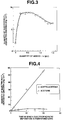
- Fig. 3 is a graph showing the relationship between the quantity of added iodine and the quantity of electrically deposited zirconia in a case where acetylacetone was used as the solvent, the applied voltage was 10 V and the time in which the electrophoretic deposition was performed was 3 minutes. As shown in Fig.
- the quantity of electrically deposited zirconia has a maximal value with respect to the quantity of added iodine. That is, facts have been confirmed that the increase in the quantity of added iodine to raise the electric conductivity initially enlarges the quantity of electrophoretic deposition and that the quantity of electrophoretic deposition decreases if the quantity of added iodine exceeds a predetermined value. Therefore, to efficiently form the film while enabling the film thickness to be controlled, the quantity of iodine to be added must be controlled in such a manner that the electric conductivity is maintained at a predetermined value.
- the quantity of iodine to be added be determined in such a manner that the electric conductivity of the suspension is included in a range near the maximal value shown in Fig. 3. Note that the maximal quantity of electrophoretic deposition is not determined simply in accordance with the quantity of iodine and the electric conductivity because it also depends upon the concentration of zirconia particles.
- Table 1 shows film forming conditions, the quantities of electrically deposited zirconia and the film qualities with various solvents in a case where respective films have been formed in accordance with the foregoing procedure.
- Solvent Quantity of added iodine g/l
- Applied voltage V
- Time in which electrodeposition is performed min
- Quantity of electrically deposited zirconia mg/cm2
- Fig. 5 shows the relationship between the applied voltage and the quantity of electrically deposited zirconia in a case where acetylacetone was used as the solvent (the time in which the electrophoretic deposition was performed: 3 minutes; the quantity of added I2: 0.6 g/litter).
- the time in which the electrophoretic deposition was performed 3 minutes; the quantity of added I2: 0.6 g/litter.
- change in the applied voltage as well as enables the quantity of electrically deposited zirconia per unit time to be controlled.
- acetylacetone was used as the solvent, stabilized zirconia particles were added at a rate of 10 g/litter and iodine was added at a rate of 0.5 g/litter so that a suspension was prepared, and the electrophoretic deposition was performed under conditions that the applied voltage was 20 V and the time in which the electrophoretic deposition was performed was one minute.
- the electric conductivity of the suspension was always monitored to control the quantity of iodine to be added in such a manner that the electric conductance was set in a range of 1 x 10 ⁇ 5 to 1 x 10 ⁇ 3 Scm ⁇ 1 with which the quantity of electrophoretic deposition was made to be the maximum value or in the vicinity of the same.
- the obtained film in the green state was dried at room temperature, followed by being sintered in the air at 1523 K to 1573 K.
- the foregoing electrophoretic deposition and sintering processes were repeated 5 to 6 times under the same conditions, so that a dense zirconia electrolytic film was obtained.
- the quantity of electrophoretic deposition was controlled by means of parameters of the voltage and the time, so that a zirconia film was obtained which had a thickness of 1 to 100 ⁇ m, which was an appropriate thickness range for a solid-electrolyte type fuel cell.
- Fig. 6 is a photograph taken by a scanning electron microscope ( SEM ) and shows a zirconia film obtained by, five times, repeating electrophoretic deposition and sintering ( 1573K for 6 hours ) on the La 0.8 Sr 0.2 MnO3 electrode substrate and having a thickness of 10 ⁇ m. As shown in Fig. 6, a fact was confirmed that a zirconia electrolytic film having the surface that exhibited excellent smoothness was obtained under the foregoing conditions.
- SEM scanning electron microscope
- Ni was applied to the surface (which was the surface opposing the La 0.8 Sr 0.2 MnO3 electrode substrate ) of the thus-formed zirconia electrolytic film so that a fuel electrode was formed and, thus, a hydrogen-oxygen concentration cell was manufactured.
- Fig. 7 is a graph showing the relationship among the sintering temperature of the zirconia film, the maximum density of the output from the hydrogen-oxygen concentration cell and the X-ray diffraction intensity of SrZrO3 in the zirconia film.
- the maximum density of the output from the hydrogen-oxygen concentration cell was raised as the sintering temperature of the zirconia film was raised, and as a result of which a maximal value was indicated when the zirconia film was sintered at 1548K.
- the reason for this can be considered that the rise in the sintering temperature raise the density of the zirconia film and the contact between the electrolytic film and the material for the electrode to be improved and therefore the maximum output density is raised.
- the zirconia film was sintered at 1548K and the electrophoretic deposition and sintering were repeated six times so that a cell was manufactured, the cell being then used to recognize the power generation characteristics.
- the realized power generation characteristics were shown in Fig. 8.
- the cell had an open-circuit electromotive force of 1.02 V, a short-circuit electric current density of 6.5 A/cm2 and a maximum output density of 1.72 W/cm2.
- the opening-circuit electromotive force of 1.02 V considerably approximated a theoretical open-circuit electromotive force of a hydrogen/oxygen fuel cell.
- the stabilization element is not limited to this.
- partially-stabilized zirconia containing the stabilization element in a smaller quantity may be used.
- the thin zirconia film is formed by employing the electrophoretic deposition method. Therefore, a very thin zirconia film having a uniform thickness can be manufactured with excellent yield attained while necessitating a simple apparatus.
- gas generation on the surface of the electrode substrate can be prevented at the time of performing the electrophoretic deposition. Therefore, density at which the zirconia particles are deposited on the electrode can be raised, and thus a dense film can be obtained. Therefore, the foregoing method is suitable for forming a zirconia film that must be formed densely. By adding iodine to the solvent in an appropriate quantity, the electric conductivity of the suspension can be raised.
- the quantity of electrically deposited zirconia per unit time can be enlarged, and therefore the film can efficiently be formed.
- the perovskite of oxide represented by general formula ( Ln 1-x A x ) y DO3 (where Ln is at least one lanthanoids, A is at least one selected from a group consisting of Ca, Sr and Ba, D is at least one selected from a group consisting of Mn, Cr and Co, and x and y respectively satisfy 0 ⁇ X ⁇ 1 and 0.8 ⁇ Y ⁇ 1 ), which has been generally used as the material of the electrodes of a solid-electrolyte type fuel cell, is used as the electrode ( the electrode substrate ), on which zirconia particles are deposited at the time of performing the electrophoretic deposition, the electrode substrate is not subjected to corrosive substances during the film forming process.
- the quantity of electrophoretic deposition is controlled by means of parameters of the voltage and the time, so that the process of forming the thin zirconia film is easily controlled.
- the solid-electrolyte type fuel cell using the zirconia film manufactured by the method according to the present invention exhibits a value considerably approximating a theoretical open-circuit electromotive force of a hydrogen/oxygen fuel cell and has excellent power generating characteristics. Therefore, the zirconia film according to the present invention is significantly suitable for use in a solid-electrolyte type fuel cell.
Abstract
(a) preparing a suspension in which partially-stabilized or stabilized zirconia particles having electric charges are dispersed in a solvent; (b) positioning a pair of electrodes in the suspension; (c) applying an electric field between the electrodes, said zirconia particles moving to the electrode and said zirconia particles being deposited on the electrode electrochemically; and (d) sintering the zirconia film to form a partially-stabilized or stabilized thin zirconia film.
Description
- The present invention relates to a method for manufacturing a thin Zirconia film, and, more particularly, to a method for manufacturing a thin Zirconia film by the electrophoretic deposition method.
- As a method of manufacturing a solid electrolytic film, in particular, a solid electrolyte film of a solid-electrolyte type fuel cell, a chemical vapor deposition ( CVD )-electrochemical vapor deposition ( EVD ) method has been disclosed in U.S.P. No. 4,609,562. The foregoing method is a method of forming a thin film having two steps that are performed at temperatures near 1273 K.
- In a case where an yttria-stabilized zirconia film is formed with the foregoing method, in a first step, reactions represented by the following formulas (1) and (2) take place on a porous substrate in such a manner that the openings in the surface of the substrate are closed:


- In a second step, reactions represented by the following formulas (3) and (4) proceed so that reactions among the reaction gases and oxygen ions generated due to the reactions represented by the following formulas (5) and (6) take place, whereby forming an yttria-stabilized zirconia film.


- However, since the raw material is, in the foregoing CVD-EVD method, supplied in the form of the gas phase, there arise problems in that the yield is excessively low, a costly apparatus is required to form the film and the film forming rate is very low. What is worse, a fact has been known that use of the perovskite oxide, that has been generally used as the material for the electrode of a solid-electrolyte type fuel cell, causes the foregoing material to be subjected to corrosive gases of metal chlorides, chlorine, hydrochloric acid and the like at about 1273 K, which is the reaction temperature, thus resulting in the material being deteriorated.
- It is an object of the invention to provide a method for manufacturing a thin zirconia film which is capable of manufacturing a very thin zirconia film having a uniform thickness with excellent yield attained while necessitating a simple apparatus.
- It is another object of the invention to provide a method for manufacturing a thin zirconia film which is capable of manufacturing a fine and thin zirconia film with an excellent efficiency.
- It is another object of the invention to provide a method for manufacturing a thin zirconia film with which the material of electrodes does not deteriorate even if a perovskite oxide is employed as the material of the electrodes.
- In order to attain the object, the present invention provides a method for manufacturing a thin zirconia film comprising the steps:
- (a) preparing a suspension in which partially-stabilized or stabilized zirconia particles having electric charges are dispersed in a solvent;
- (b) positioning a pair of electrodes in the suspension;
- (c) applying an electric field between the electrodes, said zirconia particles moving to the electrode and said zirconia particles being deposited on the electrode by an electrochemical action, thereby a zirconia film being formed; and
- (d) sintering the zirconia film to form a dense partially-stabilized or stabilized thin zirconia film.
-
- Fig. 1 is a schematic view showing an electrophoretic deposition apparatus applied to a method of manufacturing a thin zirconia film according to the present invention;
- Fig. 2 is a graph showing the relationship between the electric conductivity of a suspension and the quantity of added iodine in a case where acetylacetone is used as the solvent;
- Fig. 3 is a graph showing the dependency of the quantity of zirconia to be electrically deposited upon the quantity of added iodine;
- Fig. 4 is a graph showing the dependency of the quantity of zirconia to be electrically deposited upon the time in which the electrophoretic deposition is performed;
- Fig. 5 is a graph showing the dependency of the quantity of zirconia to be electrically deposited upon the applied voltage;
- Fig. 6 shows a photograph of a zirconia electrolyte film manufactured by the method according to the present invention and taken by a scanning electron microscope;
- Fig. 7 is a graph showing the relationship among the sintering temperature of the zirconia film, the maximum density of the output from the hydrogen-oxygen concentration cell and the X-ray diffraction intensity of SrZrO₃ in the zirconia film; and
- Fig. 8 is a graph showing the power generation characteristics of a solid-electrolyte type fuel cell to which the zirconia electrolytic film manufactured by the method according to the present invention is applied.
- In the present invention, a suspension is prepared in which partially-stabilized or stabilized zirconia particles having electric charges are dispersed in a solvent. A pair of electrodes is positioned in the suspension and an electric field is applied between the electrodes. Said zirconia particles move to the electrode and said zirconia particles are deposited on the electrode electrochemically, thereby a zirconia film being formed. The zirconia film is sintered to form a dense partially-stabilized or stabilized thin zirconia film.
- The suspension is prepared by dispersing the partially-stabilized or stabilized zirconia particles in a ketone or alcohol organic solvent. The organic solvent is preferably acetylacetone.
- In the present invention, a electric conductivity of the suspension can be adjusted by adding iodine to the suspension. The electric conductivity is monitored to measure the quantity of iodine that is consumed when the particles are electrophoretically deposited on the electrode. Iodine in a quantity corresponding to the consumed quantity is further added.
- The electrode, on which the partially-stabilized or stabilized zirconia particles are deposited, is made of a perovskite solid solution of oxide represented by general formula ( Ln1-x A x ) y DO₃ , where Ln is at least one lanthanoids, A is at least one selected from a group consisting of Ca, Sr and Ba, D is at least one selected from a group consisting of Mn, Cr and Co, and x and y respectively satisfy 0 ≦ X ≦ 1 and 0.8 ≦ Y ≦ 1.
- In the present invention, a thin zirconia film is manufactured by employing the electrophoretic deposition method with which a thin film is formed by the electrophoretic deposition. Since stabilized or partially-stabilized zirconia particles, which are the raw material for forming the zirconia film, are used while being dispersed in the solvent in a case where the thin zirconia film is formed by the electrophoretic deposition method, the yield of the raw material can be raised as compared with the CVD-EVD method in which the raw material is supplied by means of vapor of metal chlorides.
- By preparing the suspension for use in the electrodeposition by using the ketone or alcohol organic solvent, gas generation is prevented on the surface of the substrate of the electrode when the electrodeposition is performed, and therefore the density of deposition of zirconia particles is raised on the electrode. As a result, a dense film can be obtained. Thus, the foregoing method is suitable for forming an electrolytic film that must be formed densely. By adding iodine to the solvent in an appropriate quantity, the electric conductivity of the suspension can be raised, so that the quantity of zirconia that is deposited per unit time period is enlarged. Thus, the film can efficiently be formed.
- Since the electrophoretic deposition method is capable of easily controlling the quantity of deposited zirconia in accordance with the applied voltage and time in which the electrophoretic deposition is performed, the thickness of the obtained zirconia film can precisely be controlled.
- Furthermore, the electric conductivity of the suspension is always monitored at the time of performing the electrophoretic deposition to measure the quantity of consumed iodine so as to further add iodine in a quantity corresponding to the consumed quantity, whereby maintaining the electric conductivity at a predetermined level. Thus, the film can always be formed efficiently, and therefore the film thickness can accurately be controlled.
- Also in a case where the perovskite solid solution of oxide represented by general formula (Ln1-xA x ) y DO₃ ( where Ln is at least one lanthanoids, A is at least one selected from a group consisting of Ca, Sr and Ba, D is at least one selected from a group consisting of Mn, Cr and Co, and x and y respectively satisfy 0 ≦ X ≦ 1 and 0.8 ≦ Y ≦ 1 ), which has been generally used as the material of the electrodes of a solid-electrolyte type fuel cell, is used as the electrode (the electrode substrate), on which zirconia particles are deposited at the time of performing the electrophoretic deposition, the electrode substrate is not subjected to corrosive substances during the film forming process. Thus, deterioration in the substrate can significantly be prevented.
- A process of forming a zirconia film will now be described as an example of the method of manufacturing a thin zirconia film by the electrophoretic deposition method according to the present invention. In addition, results of evaluation test of a solid-electrolyte type fuel cell using the foregoing film will now be described.
- Yttria stabilized zirconia particles ( 8 mol% Y₂O₃/ZrO₂ ) were used as the electrolyte material, and various ketones, alcohols and water shown in Table 1 were used as the solvents so that a suspension for use in the electrophoretic deposition process was prepared. To adjust the electric conductivity, iodine was added in a variety of quantities. At this time, zirconia particles were added by 10 g with respect to 1 liter of the solvent.
- The thus-prepared suspension was processed with ultrasonic waves, so that the zirconia particles were dispersed sufficiently.
- As shown in Fig. 1, La0.8Sr0.2MnO₃ was, as an
electrode substrate 2 for electrically depositing zirconia, immersed in asuspension 1 in acontainer 4. Aplatinum wire 3 was spirally disposed at the counter electrode to surround the La0.8Sr0.2MnO₃ electrode substrate 2. Then, the La0.8Sr0.2MnO₃ electrode substrate 2 was set as the cathode and theplatinum wire 3 was set as the anode, and predetermined voltage was applied from a directcurrent power source 5. As a result, a green zirconia film was formed on theelectrode substrate 2. The green zirconia film formed on the substrate was dried at room temperature, and then the zirconia film was, in the air, sintered at temperature of 1523 K to 1573 K, so that a dense Zirconia film was obtained. - Fig. 2 is a graph showing the relationship between the quantity of added iodine and the electric conductivity of the suspension at 298 K ( 25°C ) in a case where acetylacetone was used as the solvent. As shown in Fig. 2, it was confirmed that the electric conductivity of the suspension is raised as the quantity of added iodine increases. Fig. 3 is a graph showing the relationship between the quantity of added iodine and the quantity of electrically deposited zirconia in a case where acetylacetone was used as the solvent, the applied voltage was 10 V and the time in which the electrophoretic deposition was performed was 3 minutes. As shown in Fig. 3, the quantity of electrically deposited zirconia has a maximal value with respect to the quantity of added iodine. That is, facts have been confirmed that the increase in the quantity of added iodine to raise the electric conductivity initially enlarges the quantity of electrophoretic deposition and that the quantity of electrophoretic deposition decreases if the quantity of added iodine exceeds a predetermined value. Therefore, to efficiently form the film while enabling the film thickness to be controlled, the quantity of iodine to be added must be controlled in such a manner that the electric conductivity is maintained at a predetermined value. That is, if the electric conductivity of the suspension is, during the electrophoretic deposition, maintained within a range near the value, at which the quantity of electrically deposited zirconia becomes the maximal value as shown in Fig. 3, a film can be formed efficiently such that a large quantity of electrophoretic deposition per unit time can be realized. Another fact that the film thickness can be controlled accurately can be understood. Therefore, it is preferable that the quantity of iodine to be added be determined in such a manner that the electric conductivity of the suspension is included in a range near the maximal value shown in Fig. 3. Note that the maximal quantity of electrophoretic deposition is not determined simply in accordance with the quantity of iodine and the electric conductivity because it also depends upon the concentration of zirconia particles.
- Table 1 shows film forming conditions, the quantities of electrically deposited zirconia and the film qualities with various solvents in a case where respective films have been formed in accordance with the foregoing procedure.
[Table 1] Solvent Quantity of added iodine (g/l) Applied voltage (V) Time in which electrodeposition is performed (min) Quantity of electrically deposited zirconia (mg/cm²) Quality of formed film Acetylacetone 0.6 10 5 14.0 uniform Acetone 0.25 300 5 2.1 uniform Cyclohexane 0.2 100 3 15.1 uniform Ethanol 0.6 100 3 38.3 many cracks Methylisobutylketone 0.2 100 3 13.8 many cracks 3-pentanone 0.2 100 3 5.6 non-uniform 4-methylacetophenone 0.2 100 3 1.1 non-uniform Water (pH = 2.5) 0 10 3 very small quantity dot-like shape Methylethylketone 0.2 300 3 very small quantity - Propiophenone 0.2 300 3 very samll quantity - - As shown in Table 1, when 3-pentanone, 4-methylacetophenone, methylethylketone, propiophenone or water was used as the solvent, the quantity of electrically deposited zirconia was very small and the film forming efficiency was unsatisfactory.
- When ethanol or methylisobutylketone is used, a large quantity of zirconia could be electrically deposited and thus a somewhat efficient film forming could be performed. However, a multiplicity of cracks were observed in the foregoing case and thus a confirmation was made that a dense electrolyte film could not easily be obtained.
- When acetylacetone, acetone or cyclohexane was used, a significantly uniform film was obtained though the quantity of electrophoretic deposition varied depending upon the quantity of added iodine, applied voltage and the time in which the electrophoretic deposition was performed.
- In particular, when acetylacetone was used as the solvent, a fact was confirmed that the quantity of electrically deposited zirconia and the time in which the electrophoretic deposition was performed has a proportional relationship as shown in Fig. 4 and thus the film thickness could be controlled widely by means of the time in which the electrophoretic deposition was performed. On the contrary, when acetone was used as the solvent, the quantity of electrically deposited zirconia was immediately saturated with respect to the time in which the electrophoretic deposition was performed as shown in Fig. 4. Thus, a fact was confirmed that a relatively thick film could not easily be obtained.
- Fig. 5 shows the relationship between the applied voltage and the quantity of electrically deposited zirconia in a case where acetylacetone was used as the solvent ( the time in which the electrophoretic deposition was performed: 3 minutes; the quantity of added I₂: 0.6 g/litter). As can be understood from Fig. 5, change in the applied voltage as well as enables the quantity of electrically deposited zirconia per unit time to be controlled.
- On the basis of the foregoing result, acetylacetone was used as the solvent, stabilized zirconia particles were added at a rate of 10 g/litter and iodine was added at a rate of 0.5 g/litter so that a suspension was prepared, and the electrophoretic deposition was performed under conditions that the applied voltage was 20 V and the time in which the electrophoretic deposition was performed was one minute. When the electrophoretic deposition was performed, the electric conductivity of the suspension was always monitored to control the quantity of iodine to be added in such a manner that the electric conductance was set in a range of 1 x 10 ⁻⁵ to 1 x 10 ⁻³ Scm ⁻¹ with which the quantity of electrophoretic deposition was made to be the maximum value or in the vicinity of the same.
- The obtained film in the green state was dried at room temperature, followed by being sintered in the air at 1523 K to 1573 K.
- The foregoing electrophoretic deposition and sintering processes were repeated 5 to 6 times under the same conditions, so that a dense zirconia electrolytic film was obtained. In the foregoing case, the quantity of electrophoretic deposition was controlled by means of parameters of the voltage and the time, so that a zirconia film was obtained which had a thickness of 1 to 100 µm, which was an appropriate thickness range for a solid-electrolyte type fuel cell.
- Fig. 6 is a photograph taken by a scanning electron microscope ( SEM ) and shows a zirconia film obtained by, five times, repeating electrophoretic deposition and sintering ( 1573K for 6 hours ) on the La0.8Sr0.2MnO₃ electrode substrate and having a thickness of 10 µm. As shown in Fig. 6, a fact was confirmed that a zirconia electrolytic film having the surface that exhibited excellent smoothness was obtained under the foregoing conditions.
- Then, Ni was applied to the surface ( which was the surface opposing the La0.8Sr0.2MnO₃ electrode substrate ) of the thus-formed zirconia electrolytic film so that a fuel electrode was formed and, thus, a hydrogen-oxygen concentration cell was manufactured.
- Fig. 7 is a graph showing the relationship among the sintering temperature of the zirconia film, the maximum density of the output from the hydrogen-oxygen concentration cell and the X-ray diffraction intensity of SrZrO₃ in the zirconia film. As shown in Fig. 7, the maximum density of the output from the hydrogen-oxygen concentration cell was raised as the sintering temperature of the zirconia film was raised, and as a result of which a maximal value was indicated when the zirconia film was sintered at 1548K. The reason for this can be considered that the rise in the sintering temperature raise the density of the zirconia film and the contact between the electrolytic film and the material for the electrode to be improved and therefore the maximum output density is raised. On the other hand, the X-ray diffraction intensity of SrZrO₃, which is the internal resistance component, is strengthened as the sintering temperature is raised, and therefore the effect of SrZrO₃ becomes dominant at about 1548K. As a result, the maximum output density can be lowered.
- Then, the zirconia film was sintered at 1548K and the electrophoretic deposition and sintering were repeated six times so that a cell was manufactured, the cell being then used to recognize the power generation characteristics. The realized power generation characteristics were shown in Fig. 8. The cell had an open-circuit electromotive force of 1.02 V, a short-circuit electric current density of 6.5 A/cm² and a maximum output density of 1.72 W/cm². The opening-circuit electromotive force of 1.02 V considerably approximated a theoretical open-circuit electromotive force of a hydrogen/oxygen fuel cell.
- Although yttria-stabilized zirconia particles were employed in the foregoing embodiment, the stabilization element is not limited to this. As a matter of course, partially-stabilized zirconia containing the stabilization element in a smaller quantity may be used.
- As described above, according to the present invention, the thin zirconia film is formed by employing the electrophoretic deposition method. Therefore, a very thin zirconia film having a uniform thickness can be manufactured with excellent yield attained while necessitating a simple apparatus. By preparing the suspension by using ketone or alcohol organic solvent, gas generation on the surface of the electrode substrate can be prevented at the time of performing the electrophoretic deposition. Therefore, density at which the zirconia particles are deposited on the electrode can be raised, and thus a dense film can be obtained. Therefore, the foregoing method is suitable for forming a zirconia film that must be formed densely. By adding iodine to the solvent in an appropriate quantity, the electric conductivity of the suspension can be raised. As a result, the quantity of electrically deposited zirconia per unit time can be enlarged, and therefore the film can efficiently be formed. Also in a case where the perovskite of oxide represented by general formula ( Ln1-x A x ) y DO₃ ( where Ln is at least one lanthanoids, A is at least one selected from a group consisting of Ca, Sr and Ba, D is at least one selected from a group consisting of Mn, Cr and Co, and x and y respectively satisfy 0 ≦ X ≦ 1 and 0.8 ≦ Y ≦ 1 ), which has been generally used as the material of the electrodes of a solid-electrolyte type fuel cell, is used as the electrode ( the electrode substrate ), on which zirconia particles are deposited at the time of performing the electrophoretic deposition, the electrode substrate is not subjected to corrosive substances during the film forming process. Thus, deterioration in the substrate can significantly be prevented. Furthermore, the quantity of electrophoretic deposition is controlled by means of parameters of the voltage and the time, so that the process of forming the thin zirconia film is easily controlled. The solid-electrolyte type fuel cell using the zirconia film manufactured by the method according to the present invention exhibits a value considerably approximating a theoretical open-circuit electromotive force of a hydrogen/oxygen fuel cell and has excellent power generating characteristics. Therefore, the zirconia film according to the present invention is significantly suitable for use in a solid-electrolyte type fuel cell.
Claims (6)
- A method for manufacturing a thin zirconia film comprising the steps:(a) preparing a suspension in which partially-stabilized or stabilized zirconia particles having electric charges are dispersed in a solvent;(b) positioning a pair of electrodes in the suspension;(c) applying an electric field between the electrodes, said zirconia particles moving to the electrode and said zirconia particles being deposited on the electrode electrochemically, thereby a zirconia film being formed; and(d) sintering the zirconia film to form a partially-stabilized or stabilized thin zirconia film.
- The method of claim 1, wherein the suspension is prepared by dispersing the partially-stabilized or stabilized zirconia particles in a ketone or alcohol organic solvent.
- The method of claim 1, wherein the organic solvent is acetylacetone.
- The method of claim 1, further comprising the step of adjusting a electric conductivity of the suspension by adding iodine to the suspension.
- The method of claim 1, further comprising the steps of:
adjusting a electric conductivity of the suspension by adding iodine to the suspension;
monitoring the electric conductivity of the suspension to measure a quantity of iodine that is consumed when the particles are electrophoretica lly deposited on the electrode; and
adding iodine in a quantity corresponding to the consumed quantity. - The method of claim 1, wherein the electrode, on which the partially-stabilized or stabilized zirconia particles are deposited, is made of a perovskite oxide represented by general formula ( Ln1-x A x ) y DO₃ , where Ln is at least one lanthanoids, A is at least one selected from a group consisting of Ca, Sr and Ba, D is at least one selected from a group consisting of Mn, Cr and Co, and x and y respectively satisfy 0 ≦ X ≦ 1 and 0.8 ≦ Y ≦ 1.
Applications Claiming Priority (2)
| Application Number | Priority Date | Filing Date | Title |
|---|---|---|---|
| JP312333/94 | 1994-11-24 | ||
| JP6312333A JP3071373B2 (en) | 1994-11-24 | 1994-11-24 | Method for producing zirconia thin film |
Publications (3)
| Publication Number | Publication Date |
|---|---|
| EP0713931A2 true EP0713931A2 (en) | 1996-05-29 |
| EP0713931A3 EP0713931A3 (en) | 1996-06-12 |
| EP0713931B1 EP0713931B1 (en) | 1999-01-13 |
Family
ID=18027983
Family Applications (1)
| Application Number | Title | Priority Date | Filing Date |
|---|---|---|---|
| EP95116114A Expired - Lifetime EP0713931B1 (en) | 1994-11-24 | 1995-10-12 | Method of manufacturing thin zirconia films by electrophoretic deposition |
Country Status (4)
| Country | Link |
|---|---|
| US (1) | US5700361A (en) |
| EP (1) | EP0713931B1 (en) |
| JP (1) | JP3071373B2 (en) |
| DE (1) | DE69507269T2 (en) |
Cited By (10)
| Publication number | Priority date | Publication date | Assignee | Title |
|---|---|---|---|---|
| WO2001086030A1 (en) * | 2000-05-10 | 2001-11-15 | Alberta Research Council Inc. | Production of hollow ceramic membranes by electrophoretic deposition |
| US6600022B1 (en) | 1996-12-26 | 2003-07-29 | Kabushiki Kaisha Hayashibara Seibutsu Kagaku Kenkyujo | Monoclonal antibody for human IL-18 receptor |
| GB2386126A (en) * | 2002-03-06 | 2003-09-10 | Ceres Power Ltd | Impermeable sintered ceramic electrolyte layer for a solid oxide fuel cell |
| US6824907B2 (en) | 2002-01-16 | 2004-11-30 | Alberta Reasearch Council, Inc. | Tubular solid oxide fuel cell stack |
| US6846588B2 (en) | 2002-01-16 | 2005-01-25 | Alberta Research Council Inc. | Hollow inorganic membranes produced by metal or composite electrodeposition |
| US6893762B2 (en) | 2002-01-16 | 2005-05-17 | Alberta Research Council, Inc. | Metal-supported tubular micro-fuel cell |
| EP1884577A2 (en) | 2006-08-05 | 2008-02-06 | Universität des Saarlandes | Method for manufacturing a ceramic mould using electrophoresis and subsequent sintering and its application |
| EP1913171A2 (en) * | 2005-08-04 | 2008-04-23 | Bar-Ilan University | Method for preparation of stable metal oxide nanoparticles suspensions |
| US7736772B2 (en) | 2002-02-14 | 2010-06-15 | Alberta Research Council, Inc. | Tubular solid oxide fuel cell stack |
| US8709674B2 (en) | 2005-04-29 | 2014-04-29 | Alberta Research Council Inc. | Fuel cell support structure |
Families Citing this family (6)
| Publication number | Priority date | Publication date | Assignee | Title |
|---|---|---|---|---|
| JPH09326258A (en) * | 1996-04-02 | 1997-12-16 | Nkk Corp | Manufacture of solid electrolyte film |
| US5919347A (en) * | 1997-04-23 | 1999-07-06 | Cerel (Ceramic Technologies) Ltd. | Method of electrophoretic deposition of laminated green bodies |
| US7018673B2 (en) * | 1998-12-02 | 2006-03-28 | Georgia Tech Research Corporation | Oxygen sensor and emission control system |
| JP4583800B2 (en) * | 2004-04-21 | 2010-11-17 | 新コスモス電機株式会社 | Hydrogen gas sensor using oxide ion conductor |
| JP4552008B2 (en) * | 2004-04-21 | 2010-09-29 | 財団法人新産業創造研究機構 | Method for producing thin-film metal oxide ion conductor used in hydrogen gas sensor |
| WO2023223596A1 (en) * | 2022-05-20 | 2023-11-23 | パナソニックIpマネジメント株式会社 | Solid electrolyte composition, solid electrolyte layer, electrode, and battery |
Citations (1)
| Publication number | Priority date | Publication date | Assignee | Title |
|---|---|---|---|---|
| US4609562A (en) | 1984-12-20 | 1986-09-02 | Westinghouse Electric Corp. | Apparatus and method for depositing coating onto porous substrate |
Family Cites Families (8)
| Publication number | Priority date | Publication date | Assignee | Title |
|---|---|---|---|---|
| US3860506A (en) * | 1966-09-12 | 1975-01-14 | Atomic Energy Commission | Electrophoretic process for coating ceramics |
| DE2837118C2 (en) * | 1978-08-25 | 1982-05-19 | Dornier System Gmbh, 7990 Friedrichshafen | Porous oxide electrodes for high temperature electrochemical cells |
| JPS6358766A (en) * | 1986-08-29 | 1988-03-14 | Toa Nenryo Kogyo Kk | Oxygen electrode structure for high temperature solid electrolyte fuel cell |
| JPH01133904A (en) * | 1987-07-17 | 1989-05-26 | Nisshin Steel Co Ltd | Production of superconductors of various shapes |
| DE3801326A1 (en) * | 1988-01-19 | 1989-07-27 | Asea Brown Boveri | METHOD FOR PRODUCING A CERAMIC SUSPENSION |
| JPH0230797A (en) * | 1988-07-21 | 1990-02-01 | Mitsubishi Metal Corp | Production of thick film by electrophoretic method |
| EP0369289A1 (en) * | 1988-11-14 | 1990-05-23 | Idemitsu Kosan Company Limited | Process for producing inorganic thin films |
| US5340779A (en) * | 1992-09-24 | 1994-08-23 | W. R. Grace & Co.-Conn. | Manufacture of conical pore ceramics by electrophoretic deposition |
-
1994
- 1994-11-24 JP JP6312333A patent/JP3071373B2/en not_active Expired - Fee Related
-
1995
- 1995-09-26 US US08/533,946 patent/US5700361A/en not_active Expired - Fee Related
- 1995-10-12 EP EP95116114A patent/EP0713931B1/en not_active Expired - Lifetime
- 1995-10-12 DE DE69507269T patent/DE69507269T2/en not_active Expired - Fee Related
Patent Citations (1)
| Publication number | Priority date | Publication date | Assignee | Title |
|---|---|---|---|---|
| US4609562A (en) | 1984-12-20 | 1986-09-02 | Westinghouse Electric Corp. | Apparatus and method for depositing coating onto porous substrate |
Cited By (15)
| Publication number | Priority date | Publication date | Assignee | Title |
|---|---|---|---|---|
| US6600022B1 (en) | 1996-12-26 | 2003-07-29 | Kabushiki Kaisha Hayashibara Seibutsu Kagaku Kenkyujo | Monoclonal antibody for human IL-18 receptor |
| WO2001086030A1 (en) * | 2000-05-10 | 2001-11-15 | Alberta Research Council Inc. | Production of hollow ceramic membranes by electrophoretic deposition |
| US7452622B2 (en) | 2002-01-16 | 2008-11-18 | Alberta Research Council Inc. | Metal-supported tubular fuel cell |
| US6824907B2 (en) | 2002-01-16 | 2004-11-30 | Alberta Reasearch Council, Inc. | Tubular solid oxide fuel cell stack |
| US6846588B2 (en) | 2002-01-16 | 2005-01-25 | Alberta Research Council Inc. | Hollow inorganic membranes produced by metal or composite electrodeposition |
| US6893762B2 (en) | 2002-01-16 | 2005-05-17 | Alberta Research Council, Inc. | Metal-supported tubular micro-fuel cell |
| US7736772B2 (en) | 2002-02-14 | 2010-06-15 | Alberta Research Council, Inc. | Tubular solid oxide fuel cell stack |
| GB2386126B (en) * | 2002-03-06 | 2006-03-08 | Ceres Power Ltd | Forming an impermeable sintered ceramic electrolyte layer on a metallic foil substrate for solid oxide fuel cell |
| GB2386126A (en) * | 2002-03-06 | 2003-09-10 | Ceres Power Ltd | Impermeable sintered ceramic electrolyte layer for a solid oxide fuel cell |
| US7833642B2 (en) | 2002-03-06 | 2010-11-16 | Ceres Intellectual Property Company Limited | Forming an impermeable sintered ceramic electrolyte layer on a metallic foil substrate for solid oxide fuel cell |
| US8709674B2 (en) | 2005-04-29 | 2014-04-29 | Alberta Research Council Inc. | Fuel cell support structure |
| EP1913171A2 (en) * | 2005-08-04 | 2008-04-23 | Bar-Ilan University | Method for preparation of stable metal oxide nanoparticles suspensions |
| EP1913171A4 (en) * | 2005-08-04 | 2011-07-06 | 3Gsolar Ltd | Method for preparation of stable metal oxide nanoparticles suspensions |
| EP1884577A2 (en) | 2006-08-05 | 2008-02-06 | Universität des Saarlandes | Method for manufacturing a ceramic mould using electrophoresis and subsequent sintering and its application |
| EP1884577A3 (en) * | 2006-08-05 | 2009-05-20 | Universität des Saarlandes | Method for manufacturing a ceramic mould using electrophoresis and subsequent sintering and its application |
Also Published As
| Publication number | Publication date |
|---|---|
| JP3071373B2 (en) | 2000-07-31 |
| EP0713931A3 (en) | 1996-06-12 |
| US5700361A (en) | 1997-12-23 |
| JPH08144092A (en) | 1996-06-04 |
| DE69507269D1 (en) | 1999-02-25 |
| EP0713931B1 (en) | 1999-01-13 |
| DE69507269T2 (en) | 1999-06-17 |
Similar Documents
| Publication | Publication Date | Title |
|---|---|---|
| EP0713931A2 (en) | Method of manufacturing thin zirconia films by electrophoretic deposition | |
| Hengerer et al. | Orientation dependence of charge‐transfer processes on TiO2 (Anatase) single crystals | |
| EP0476808B1 (en) | Process for producing a composite body and use in a solid oxide fuel cell | |
| EP0524013B1 (en) | Solid electrolyte type fuel cell and method for producing the same | |
| Boodts et al. | Hydrogen evolution on iridium oxide cathodes | |
| US4767518A (en) | Cermet electrode | |
| EP0253459B1 (en) | Electrodes for solid oxide electrolyte electrochemical cells | |
| Cai et al. | Oxidation of zinc in alkaline solutions studied by electrochemical impedance spectroscopy | |
| US5527633A (en) | Solid oxide fuel cells, a process for producing solid electrolyte films and a process for producing solid oxide fuel cells | |
| Wang et al. | The role of 8 mol% yttria stabilized zirconia in the improvement of electrochemical performance of lanthanum manganite composite electrodes | |
| JP3542802B2 (en) | How to attach a cermet electrode layer to a sintered electrolyte | |
| Ishihara et al. | Preparation of Yttria-Stabilized Zirconia Films for Solid Oxide Fuel Cells by Electrophoretic Deposition Method. | |
| Tomczyk et al. | Kinetics of the oxygen electrode reaction in molten Li+ Na carbonate eutectic: Part 5. Linear voltammetric and chronoamperometric data for the reduction processes at NiO monocrystalline electrodes | |
| JPH11219710A (en) | Electrode of solid electrolyte fuel cell and manufacture thereof | |
| JPH08162120A (en) | Solid electrolyte type electrochemical cell | |
| Giilzow et al. | New dry preparation technique for membrane electrode assemblies for PEM fuel cells | |
| Swette et al. | Oxygen electrodes for rechargeable alkaline fuel cells. III | |
| Sasaki et al. | Effect of La3+ ion on the electrodeposition of manganese and cobalt oxides | |
| Van Manen et al. | High temperature cyclic voltammetry on metal/metal oxide systems | |
| JPH09326258A (en) | Manufacture of solid electrolyte film | |
| Ishihara et al. | Electrophoretic deposition of Y2O3-stabilized ZrO2 on the porous La0. 8Sr0. 2MnO3 cathode substrate for SOFC | |
| Ostapenko | Potentiostatic Investigation of the Vitreous Carbon/RbCu~ 4Cl~ 3I~ 2 Interface | |
| Wang et al. | Electrocatalytic properties of an Sr 0.25 Bi 0.5 FeO 3–δ/LSGM interface | |
| Ishihara et al. | Electrophoretic deposition of stabilized zirconia for solid oxide fuel cells | |
| CA1129809A (en) | Electrolysis electrode with coating of tin dioxide and platinum group metal |
Legal Events
| Date | Code | Title | Description |
|---|---|---|---|
| PUAI | Public reference made under article 153(3) epc to a published international application that has entered the european phase |
Free format text: ORIGINAL CODE: 0009012 |
|
| PUAL | Search report despatched |
Free format text: ORIGINAL CODE: 0009013 |
|
| 17P | Request for examination filed |
Effective date: 19951012 |
|
| AK | Designated contracting states |
Kind code of ref document: A2 Designated state(s): DE GB |
|
| AK | Designated contracting states |
Kind code of ref document: A3 Designated state(s): DE GB |
|
| 17Q | First examination report despatched |
Effective date: 19961115 |
|
| GRAG | Despatch of communication of intention to grant |
Free format text: ORIGINAL CODE: EPIDOS AGRA |
|
| GRAG | Despatch of communication of intention to grant |
Free format text: ORIGINAL CODE: EPIDOS AGRA |
|
| GRAH | Despatch of communication of intention to grant a patent |
Free format text: ORIGINAL CODE: EPIDOS IGRA |
|
| GRAH | Despatch of communication of intention to grant a patent |
Free format text: ORIGINAL CODE: EPIDOS IGRA |
|
| GRAA | (expected) grant |
Free format text: ORIGINAL CODE: 0009210 |
|
| AK | Designated contracting states |
Kind code of ref document: B1 Designated state(s): DE GB |
|
| REF | Corresponds to: |
Ref document number: 69507269 Country of ref document: DE Date of ref document: 19990225 |
|
| PLBE | No opposition filed within time limit |
Free format text: ORIGINAL CODE: 0009261 |
|
| STAA | Information on the status of an ep patent application or granted ep patent |
Free format text: STATUS: NO OPPOSITION FILED WITHIN TIME LIMIT |
|
| 26N | No opposition filed | ||
| REG | Reference to a national code |
Ref country code: GB Ref legal event code: IF02 |
|
| PGFP | Annual fee paid to national office [announced via postgrant information from national office to epo] |
Ref country code: GB Payment date: 20021009 Year of fee payment: 8 |
|
| PGFP | Annual fee paid to national office [announced via postgrant information from national office to epo] |
Ref country code: DE Payment date: 20021017 Year of fee payment: 8 |
|
| PG25 | Lapsed in a contracting state [announced via postgrant information from national office to epo] |
Ref country code: GB Free format text: LAPSE BECAUSE OF NON-PAYMENT OF DUE FEES Effective date: 20031012 |
|
| PG25 | Lapsed in a contracting state [announced via postgrant information from national office to epo] |
Ref country code: DE Free format text: LAPSE BECAUSE OF NON-PAYMENT OF DUE FEES Effective date: 20040501 |
|
| GBPC | Gb: european patent ceased through non-payment of renewal fee |
Effective date: 20031012 |