EP0712194A2 - Fast charging of different types of batteries - Google Patents
Fast charging of different types of batteries Download PDFInfo
- Publication number
- EP0712194A2 EP0712194A2 EP95307865A EP95307865A EP0712194A2 EP 0712194 A2 EP0712194 A2 EP 0712194A2 EP 95307865 A EP95307865 A EP 95307865A EP 95307865 A EP95307865 A EP 95307865A EP 0712194 A2 EP0712194 A2 EP 0712194A2
- Authority
- EP
- European Patent Office
- Prior art keywords
- charging
- battery
- detected
- voltage
- batteries
- Prior art date
- Legal status (The legal status is an assumption and is not a legal conclusion. Google has not performed a legal analysis and makes no representation as to the accuracy of the status listed.)
- Granted
Links
Images


Classifications
-
- H—ELECTRICITY
- H02—GENERATION; CONVERSION OR DISTRIBUTION OF ELECTRIC POWER
- H02J—CIRCUIT ARRANGEMENTS OR SYSTEMS FOR SUPPLYING OR DISTRIBUTING ELECTRIC POWER; SYSTEMS FOR STORING ELECTRIC ENERGY
- H02J7/00—Circuit arrangements for charging or depolarising batteries or for supplying loads from batteries
- H02J7/007—Regulation of charging or discharging current or voltage
- H02J7/00712—Regulation of charging or discharging current or voltage the cycle being controlled or terminated in response to electric parameters
- H02J7/007182—Regulation of charging or discharging current or voltage the cycle being controlled or terminated in response to electric parameters in response to battery voltage
- H02J7/007184—Regulation of charging or discharging current or voltage the cycle being controlled or terminated in response to electric parameters in response to battery voltage in response to battery voltage gradient
Definitions
- the invention relates to a method for fast charging of different types of chargeable batteries and particularly a method for terminating the charging of a battery when a certain decrease in the battery voltage is detected when the battery is fully charged and the charge begins to drop.
- the invention also relates to charging apparatus.
- Ni-Cd batteries like nickel-cadmium (Ni-Cd) batteries. Batteries are often charged with separate chargers; e.g. with desktop chargers intended for charging batteries of mobile stations/mobile telephones. In some cases it is felt that removing the batteries from the telephone for charging is inconvenient because then the telephone cannot be used during the charging. However, there are several different chargers that can be attached to a battery-operated device to charge the batteries while they are in the device, e.g. in a mobile telephone. Thus, the telephone can be used during the charging of the batteries.
- - ⁇ V method ie. the negative delta voltage method. It has been used with relative success for Ni-Cd batteries.
- a battery is charged with a constant current until the voltage of the battery reaches its peak value and begins to drop. This voltage drop caused by overcharge is typical for a fully charged Ni-Cd battery, it can be detected and therefore it can be used as a criterion for terminating the charging.
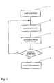
- the predetermined voltage drop for a nickel-cadmium battery is set at 20 mV, which then is the criterion mentioned above. This method is illustrated in Figure 1.
- step 1 of Figure 1 the charging of a battery is started.
- step 2 the charging continues and in step 3 the charge is increased to the peak value.
- step 4 it is monitored whether the voltage of the battery has begun to decrease. If that is not the case, charging continues. If the voltage has decreased, ie. a predetermined drop - ⁇ V, say, -20 mV, is detected, the charging is terminated in step 5.
- a predetermined drop - ⁇ V say, -20 mV
- Ni-MH batteries are becoming popular.
- the difference between Ni-Cd and Ni-MH batteries is that in a Ni-MH battery the voltage drop caused by overcharge is quite small, considerably smaller than that of a Ni-Cd battery.
- said predetermined voltage drop value (- ⁇ V) has to be set rather low. This makes the detector very sensitive to disturbances. Disturbances may be caused by external electric fields, temperature, etc.
- FIG. 2 presents a flowchart for a charging method utilizing such known technique.
- the charging of a battery is started in step 1, then the battery is being charged in step 2 until a certain charge condition has been met in step 6, e.g. the charge level of the battery has increased by 5 %.
- the charge of the battery is checked in step 7 and when the charge has stopped increasing it is assumed that the battery is fully charged and a decision is made in step 5 to stop the charging.
- the period of time over which the voltages are compared has to be long enough.
- the voltage of Ni-Cd and Ni-MH batteries increases until the battery reaches full charge.
- the voltage increase is rather small in the mid-stages of charging. According to measurement results, it then easily seems that the voltage has remained the same or even decreased, especially when disturbances affect the measurement results, as was stated before, in connection with Figure 1. Therefore, the peak detection comparison time has to be long enough lest the charging be terminated too soon.
- a disadvantage of the method is that when the battery is fully charged, the charging must be continued in excess of the comparison time so as to ensure full charge. This results in that the battery will be overcharged every time due to the long comparison time.
- a voltage drop - ⁇ V is detected, the length of the time over which the voltage drop is detected is measured, the voltage drop - ⁇ V is integrated over the measured time, the integration result is compared to a predetermined total value, and the charging of the battery is stopped when the integration result exceeds said total value.
- the method can be used for charging at least Ni-Cd and Ni-MH batteries with a same charger.
- the method according to the invention may suitably be used for charging and terminating the charging of batteries of mobile stations.
- the invention also relates to a charging apparatus according to claim 7.
- step 1 charging is first started in step 1, after which the battery is being charged in step 2.
- the decrease is detected according to the invention as a voltage drop - ⁇ V in the charge decrease detection step 8.
- the time during which the charge decrease is detected is measured in step 9.
- the measured voltage drop - ⁇ V is integrated over the measured decrease time in step 10.
- the integration result is considered in step 11, ie. it is compared to a predetermined total value. If the integration result exceeds said total value in step 11, charging will be terminated in step 5. This means that the drop of the battery voltage has been rapid enough and it is assumed that the battery is fully charged. If the integration result does not exceed said total value in step 11, it is returned to step 2, ie.
- charging is continued.
- integrating is continued only for a predetermined observation period and if the integration result does not reach said total value within the observation period, integrating will be stopped since it then can be assumed that the detected drop was caused by an external disturbance or an internal phenomenon in the battery. In this situation, charging is continued and integration will be started again when a new predetermined drop is detected.
- An idea behind solutions according to the invention is to detect a predetermined voltage drop as small as possible and integrate it over the measured period of time. If the voltage drop is very small, near zero, it cannot be determined with certainty in prior art solutions whether the voltage drop was caused by an external disturbance or some other instability in the battery voltage curve. In the solution described above, it is obtained by means of integration in step 10 the voltage drop rate with the help of which it is made a decision in step 11 on the termination of charging, after which the charging is terminated in step 5. If the - ⁇ V is less pronounced the lower is the relative charging current. With this solution also larger batteries and/or smaller charging currents can be used without any change to present values.
Abstract
Description
- The invention relates to a method for fast charging of different types of chargeable batteries and particularly a method for terminating the charging of a battery when a certain decrease in the battery voltage is detected when the battery is fully charged and the charge begins to drop. The invention also relates to charging apparatus.
- There are several known methods for charging rechargeable batteries like nickel-cadmium (Ni-Cd) batteries. Batteries are often charged with separate chargers; e.g. with desktop chargers intended for charging batteries of mobile stations/mobile telephones. In some cases it is felt that removing the batteries from the telephone for charging is inconvenient because then the telephone cannot be used during the charging. However, there are several different chargers that can be attached to a battery-operated device to charge the batteries while they are in the device, e.g. in a mobile telephone. Thus, the telephone can be used during the charging of the batteries.
- Before, there was the problem that chargers used rather small charge currents and a battery-operated device had to be out of use quite a long time, say, eight hours or more, while the batteries were being charged. For this reason, rapid chargers have been developed that are capable of charging batteries in quite a short time, in 1/2 to 3 hours.
- Several problems had to be solved in order to facilitate rapid charging. One of the biggest problems was the overcharging of batteries which leads to overheating of batteries. Overheating damages the batteries in long term and the overcharge may cause the battery cell to leak.
- In known rapid chargers, most of these problems have been solved by monitoring certain parameters of the battery, like the charge and internal temperature of the battery. Some rapid chargers attempt to prevent battery overcharge by applying a certain limited charging time in the charger. This, however, cannot reliably prevent battery overcharge. Hence, the problem is how to stop charging at the right moment when the battery is fully charged.
- One of the most widely known methods for terminating the charging of a battery is the so-called -ΔV method, ie. the negative delta voltage method. It has been used with relative success for Ni-Cd batteries. In this method a battery is charged with a constant current until the voltage of the battery reaches its peak value and begins to drop. This voltage drop caused by overcharge is typical for a fully charged Ni-Cd battery, it can be detected and therefore it can be used as a criterion for terminating the charging. In many applications, the predetermined voltage drop for a nickel-cadmium battery is set at 20 mV, which then is the criterion mentioned above. This method is illustrated in Figure 1.
- In
step 1 of Figure 1 the charging of a battery is started. Instep 2, the charging continues and instep 3 the charge is increased to the peak value. In step 4, it is monitored whether the voltage of the battery has begun to decrease. If that is not the case, charging continues. If the voltage has decreased, ie. a predetermined drop -ΔV, say, -20 mV, is detected, the charging is terminated instep 5. - Nowadays, Ni-MH batteries are becoming popular. The difference between Ni-Cd and Ni-MH batteries is that in a Ni-MH battery the voltage drop caused by overcharge is quite small, considerably smaller than that of a Ni-Cd battery. In order to enable charging of Ni-MH batteries with a charger that has been used to charge Ni-Cd batteries, said predetermined voltage drop value (-ΔV) has to be set rather low. This makes the detector very sensitive to disturbances. Disturbances may be caused by external electric fields, temperature, etc. In addition, there may occur a voltage drop in the middle of charging, as a typical characteristic of the battery. So there is the risk that charging is prematurely terminated before the battery is fully charged, even in the beginning of charging.
- Another known method for the termination of charging is to use peak value detection. Figure 2 presents a flowchart for a charging method utilizing such known technique. First, the charging of a battery is started in
step 1, then the battery is being charged instep 2 until a certain charge condition has been met instep 6, e.g. the charge level of the battery has increased by 5 %. Next, the charge of the battery is checked instep 7 and when the charge has stopped increasing it is assumed that the battery is fully charged and a decision is made instep 5 to stop the charging. - In the method illustrated in Figure 2, the period of time over which the voltages are compared has to be long enough. The voltage of Ni-Cd and Ni-MH batteries increases until the battery reaches full charge. However, the voltage increase is rather small in the mid-stages of charging. According to measurement results, it then easily seems that the voltage has remained the same or even decreased, especially when disturbances affect the measurement results, as was stated before, in connection with Figure 1. Therefore, the peak detection comparison time has to be long enough lest the charging be terminated too soon. Then a disadvantage of the method is that when the battery is fully charged, the charging must be continued in excess of the comparison time so as to ensure full charge. This results in that the battery will be overcharged every time due to the long comparison time.
- It is an object of embodiments of the present invention to bring about a method for charging and particularly for terminating the charging of chargeable batteries, which may help to avoid the problems described above.
- Accordingly, it is characteristic of the inventive method that a voltage drop -ΔV is detected, the length of the time over which the voltage drop is detected is measured, the voltage drop -ΔV is integrated over the measured time, the integration result is compared to a predetermined total value, and the charging of the battery is stopped when the integration result exceeds said total value. The method can be used for charging at least Ni-Cd and Ni-MH batteries with a same charger.
- The method according to the invention may suitably be used for charging and terminating the charging of batteries of mobile stations.
- The invention also relates to a charging apparatus according to
claim 7. - Below, an example of an embodiment according to the invention is described in detail, with reference to the enclosed drawings where
- Figures 1 and 2 illustrate the prior art methods described above and
- Figure 3 shows a flowchart of a charging method according to the invention.
- Below there follows a description of a solution according to the invention with reference to Figure 3 which illustrates the implementation of a solution according to the invention in the form of a simplified flowchart.
- In the new method, charging is first started in
step 1, after which the battery is being charged instep 2. When the battery is fully charged and the charge begins to decrease, the decrease is detected according to the invention as a voltage drop -ΔV in the charge decreasedetection step 8. Next, the time during which the charge decrease is detected is measured instep 9. After that, the measured voltage drop -ΔV is integrated over the measured decrease time instep 10. Next, the integration result is considered instep 11, ie. it is compared to a predetermined total value. If the integration result exceeds said total value instep 11, charging will be terminated instep 5. This means that the drop of the battery voltage has been rapid enough and it is assumed that the battery is fully charged. If the integration result does not exceed said total value instep 11, it is returned tostep 2, ie. charging is continued. In addition, integrating is continued only for a predetermined observation period and if the integration result does not reach said total value within the observation period, integrating will be stopped since it then can be assumed that the detected drop was caused by an external disturbance or an internal phenomenon in the battery. In this situation, charging is continued and integration will be started again when a new predetermined drop is detected. - An idea behind solutions according to the invention is to detect a predetermined voltage drop as small as possible and integrate it over the measured period of time. If the voltage drop is very small, near zero, it cannot be determined with certainty in prior art solutions whether the voltage drop was caused by an external disturbance or some other instability in the battery voltage curve. In the solution described above, it is obtained by means of integration in
step 10 the voltage drop rate with the help of which it is made a decision instep 11 on the termination of charging, after which the charging is terminated instep 5. If the -ΔV is less pronounced the lower is the relative charging current. With this solution also larger batteries and/or smaller charging currents can be used without any change to present values. - With solutions according to the invention it is possible to prevent battery overcharge reliably and efficiently. The advantage of these solutions is that the integration time can be relatively short and hence the overcharge remains quite small. On the other hand, the same predetermined drop can be applied to the charging of both Ni-Cd and Ni-MH batteries with a same charger and/or same charge control program.
Claims (7)
- A method for terminating the charging (2) of a battery when a certain decrease in the battery voltage is detected when the battery is fully charged and the charge begins to decrease, characterized in that- a voltage drop -ΔV is detected (in step 8),- the length of the time during which the voltage drop is detected is measured (in step 9),- the detected voltage drop -ΔV is integrated over the measured time (in step 10),- the integration result is compared (in step 11) to a predetermined total value, and- the charging of the battery is terminated (in step 5) when the integration result exceeds said total value.
- The method of claim 1, characterized in that for the predetermined drop to be detected it is selected the smallest possible voltage drop -ΔV that can be detected.
- The method of claim 1 or 2, characterized in that, in addition, integration (in step 10) is continued only for a predetermined observation period and if the integration result does not reach said total value within the observation period, the integration is stopped and will be started again from the beginning when a new predetermined drop is detected (in step 8).
- The method of any one of the preceding claims, characterized in that it is applied for terminating the charging of different types of batteries.
- The method of claim 4, characterized in that it is used to charge at least Ni-Cd and Ni-MH batteries with a same charger and/or same charge control program.
- Use of the method of any one of the preceding claims for charging and terminating the charging of batteries of mobile stations.
- Charging apparatus for charging a battery, comprising:voltage detection means for sensing the voltage of the battery and detecting dropping of that voltage;timing means for measuring a length of time during which a drop in the battery voltage is detected;integrating means for integrating the drop in battery voltage over the measured length of time;comparison means for comparing the result of the said integration with a predetermined value; andcontrol means for terminating charging of the battery when the said result exceeds the predetermined value.
Applications Claiming Priority (2)
| Application Number | Priority Date | Filing Date | Title |
|---|---|---|---|
| FI945309 | 1994-11-11 | ||
| FI945309A FI99176C (en) | 1994-11-11 | 1994-11-11 | Method for fast charging of different types of batteries |
Publications (3)
| Publication Number | Publication Date |
|---|---|
| EP0712194A2 true EP0712194A2 (en) | 1996-05-15 |
| EP0712194A3 EP0712194A3 (en) | 1996-08-14 |
| EP0712194B1 EP0712194B1 (en) | 1999-03-31 |
Family
ID=8541780
Family Applications (1)
| Application Number | Title | Priority Date | Filing Date |
|---|---|---|---|
| EP95307865A Expired - Lifetime EP0712194B1 (en) | 1994-11-11 | 1995-11-03 | Fast charging of different types of batteries |
Country Status (4)
| Country | Link |
|---|---|
| US (1) | US5625274A (en) |
| EP (1) | EP0712194B1 (en) |
| DE (1) | DE69508702T2 (en) |
| FI (1) | FI99176C (en) |
Cited By (1)
| Publication number | Priority date | Publication date | Assignee | Title |
|---|---|---|---|---|
| EP2450527A1 (en) | 2009-08-14 | 2012-05-09 | Services Pétroliers Schlumberger | Method of displaying well drilling operations |
Families Citing this family (9)
| Publication number | Priority date | Publication date | Assignee | Title |
|---|---|---|---|---|
| US6229285B1 (en) * | 1997-10-03 | 2001-05-08 | Georgia Tech Research Corporation | Detector for rapid charging and method |
| US6094033A (en) * | 1998-10-02 | 2000-07-25 | Georgia Tech Research Corporation | Battery state of charge detector with rapid charging capability and method |
| FI109861B (en) | 1998-01-05 | 2002-10-15 | Nokia Corp | A method for efficiently utilizing cell broadcasting capacity |
| US6157172A (en) | 1999-06-11 | 2000-12-05 | Nokia Mobile Phones Limited | Charging method and device |
| KR100326704B1 (en) * | 1999-07-08 | 2002-03-12 | 이계안 | A battery charging device and a method thereof for electric car |
| US6100672A (en) * | 1999-08-11 | 2000-08-08 | Nokia Mobile Phones Limited | Start up charging control |
| US20040056065A1 (en) * | 2002-09-25 | 2004-03-25 | Wasko Erik C. | Multi-track nail insertion apparatus |
| US7110896B2 (en) * | 2003-04-22 | 2006-09-19 | Hewlett-Packard Development Company, L.P. | System and method for displaying battery status and other parameters of a portable electronic device in a power-off state |
| US7221125B2 (en) * | 2003-11-06 | 2007-05-22 | Y. Ding | System and method for charging a battery |
Family Cites Families (15)
| Publication number | Priority date | Publication date | Assignee | Title |
|---|---|---|---|---|
| US4306183A (en) * | 1979-03-14 | 1981-12-15 | Lucas Industries Limited | Voltage regulation circuit for a solar cell charging system |
| JP2689564B2 (en) * | 1988-01-29 | 1997-12-10 | 日本電気株式会社 | Charge control device |
| JPH088748B2 (en) * | 1988-11-11 | 1996-01-29 | 三洋電機株式会社 | Full charge detection circuit |
| US5206579A (en) * | 1990-02-26 | 1993-04-27 | Nippon Densan Corporation | Battery charger and charge controller therefor |
| US5200690A (en) * | 1990-10-01 | 1993-04-06 | Sanyo Electric Co., Ltd. | Quick charge control apparatus and control method thereof |
| US5187425A (en) * | 1990-11-09 | 1993-02-16 | Ast Research, Inc. | Rechargeable battery controller |
| US5225763A (en) * | 1991-03-20 | 1993-07-06 | Sherwood Medical Company | Battery charging circuit and method for an ambulatory feeding pump |
| US5177427A (en) * | 1991-03-22 | 1993-01-05 | H. M. Electronics, Inc. | Battery charging system and method for preventing false switching from fast charge to trickle charge |
| JPH05137271A (en) * | 1991-11-08 | 1993-06-01 | Nec Corp | Charging method of battery |
| US5350995A (en) * | 1992-07-17 | 1994-09-27 | Asahi Kogaku Kogyo Kabushiki Kaisha | Battery charger for charging both a frequently and infrequently used battery |
| US5467005A (en) * | 1992-08-11 | 1995-11-14 | Makita Corporation | Battery charger which accounts for initial surge in battery voltage and which is immune to noise during completion of charging |
| JPH082149B2 (en) * | 1992-08-20 | 1996-01-10 | 株式会社マキタ | Charger |
| DE69409863T2 (en) * | 1993-05-05 | 1998-10-08 | Sgs Thomson Microelectronics | battery charger |
| DE69419362T2 (en) * | 1993-05-05 | 1999-11-04 | St Microelectronics Pte Ltd | battery charger |
| DE4339363C2 (en) * | 1993-11-18 | 1996-05-15 | Telefunken Microelectron | Charging procedure for accumulators |
-
1994
- 1994-11-11 FI FI945309A patent/FI99176C/en active
-
1995
- 1995-11-03 EP EP95307865A patent/EP0712194B1/en not_active Expired - Lifetime
- 1995-11-03 DE DE69508702T patent/DE69508702T2/en not_active Expired - Lifetime
- 1995-11-08 US US08/555,206 patent/US5625274A/en not_active Expired - Lifetime
Non-Patent Citations (1)
| Title |
|---|
| None |
Cited By (1)
| Publication number | Priority date | Publication date | Assignee | Title |
|---|---|---|---|---|
| EP2450527A1 (en) | 2009-08-14 | 2012-05-09 | Services Pétroliers Schlumberger | Method of displaying well drilling operations |
Also Published As
| Publication number | Publication date |
|---|---|
| FI945309A (en) | 1996-05-12 |
| FI99176C (en) | 1997-10-10 |
| US5625274A (en) | 1997-04-29 |
| FI99176B (en) | 1997-06-30 |
| EP0712194A3 (en) | 1996-08-14 |
| DE69508702D1 (en) | 1999-05-06 |
| FI945309A0 (en) | 1994-11-11 |
| DE69508702T2 (en) | 1999-11-04 |
| EP0712194B1 (en) | 1999-03-31 |
Similar Documents
| Publication | Publication Date | Title |
|---|---|---|
| US5627451A (en) | Control method and control apparatus for secondary battery charging in constant current charging method | |
| US6366056B1 (en) | Battery charger for lithium based batteries | |
| EP2083495B1 (en) | Battery pack and method of charging the same | |
| US5747970A (en) | Battery charger charging time control | |
| US6172487B1 (en) | Method and apparatus for charging batteries | |
| US6333621B2 (en) | Method of fast-charging of a rechargeable battery | |
| US6111389A (en) | Rapidly charging a battery without overcharging | |
| EP0712194B1 (en) | Fast charging of different types of batteries | |
| US5642032A (en) | Charging method for a battery assembly including a plurality of secondary batteries | |
| JP2003153454A (en) | Method of detecting deterioration of secondary battery and battery charger provided with function of detecting deterioration | |
| Gonzalez et al. | Considerations to improve the practical design of universal and full-effective NiCd/NiMH battery fast-chargers | |
| US6249107B1 (en) | Method of charging a battery in a mobile charger | |
| JPH08103032A (en) | Charging for secondary battery | |
| US6583605B2 (en) | Charging method and charger | |
| JP3092394B2 (en) | Secondary battery charging method and device | |
| Gonzalez et al. | Accurate detection algorithm of battery full-capacity under fast-charge | |
| JPH0737621A (en) | Device for judging residual capacity of secondary battery and charging device using it | |
| JP2000182677A (en) | Secondary battery charging device | |
| JPH04267078A (en) | Combined battery and charging method thereof | |
| KR0141680B1 (en) | Charging method of battery | |
| JP2001112185A (en) | Apparatus and method for control of charging | |
| JP3402757B2 (en) | Secondary battery charging method and secondary battery charging device | |
| JP3917046B2 (en) | Charging circuit, charging method, and portable terminal equipped with the charging circuit | |
| JP3499902B2 (en) | Rechargeable battery charger | |
| JP3144394B2 (en) | Charging device and charging method |
Legal Events
| Date | Code | Title | Description |
|---|---|---|---|
| PUAI | Public reference made under article 153(3) epc to a published international application that has entered the european phase |
Free format text: ORIGINAL CODE: 0009012 |
|
| AK | Designated contracting states |
Kind code of ref document: A2 Designated state(s): DE FR GB IT NL SE |
|
| PUAL | Search report despatched |
Free format text: ORIGINAL CODE: 0009013 |
|
| AK | Designated contracting states |
Kind code of ref document: A3 Designated state(s): DE FR GB IT NL SE |
|
| 17P | Request for examination filed |
Effective date: 19970214 |
|
| GRAG | Despatch of communication of intention to grant |
Free format text: ORIGINAL CODE: EPIDOS AGRA |
|
| 17Q | First examination report despatched |
Effective date: 19980810 |
|
| GRAG | Despatch of communication of intention to grant |
Free format text: ORIGINAL CODE: EPIDOS AGRA |
|
| GRAH | Despatch of communication of intention to grant a patent |
Free format text: ORIGINAL CODE: EPIDOS IGRA |
|
| GRAH | Despatch of communication of intention to grant a patent |
Free format text: ORIGINAL CODE: EPIDOS IGRA |
|
| GRAA | (expected) grant |
Free format text: ORIGINAL CODE: 0009210 |
|
| AK | Designated contracting states |
Kind code of ref document: B1 Designated state(s): DE FR GB IT NL SE |
|
| PG25 | Lapsed in a contracting state [announced via postgrant information from national office to epo] |
Ref country code: SE Free format text: THE PATENT HAS BEEN ANNULLED BY A DECISION OF A NATIONAL AUTHORITY Effective date: 19990331 Ref country code: NL Free format text: LAPSE BECAUSE OF FAILURE TO SUBMIT A TRANSLATION OF THE DESCRIPTION OR TO PAY THE FEE WITHIN THE PRESCRIBED TIME-LIMIT Effective date: 19990331 |
|
| REF | Corresponds to: |
Ref document number: 69508702 Country of ref document: DE Date of ref document: 19990506 |
|
| ET | Fr: translation filed | ||
| NLV1 | Nl: lapsed or annulled due to failure to fulfill the requirements of art. 29p and 29m of the patents act | ||
| PLBE | No opposition filed within time limit |
Free format text: ORIGINAL CODE: 0009261 |
|
| STAA | Information on the status of an ep patent application or granted ep patent |
Free format text: STATUS: NO OPPOSITION FILED WITHIN TIME LIMIT |
|
| 26N | No opposition filed | ||
| REG | Reference to a national code |
Ref country code: GB Ref legal event code: IF02 |
|
| REG | Reference to a national code |
Ref country code: GB Ref legal event code: 732E |
|
| PG25 | Lapsed in a contracting state [announced via postgrant information from national office to epo] |
Ref country code: IT Free format text: LAPSE BECAUSE OF NON-PAYMENT OF DUE FEES;WARNING: LAPSES OF ITALIAN PATENTS WITH EFFECTIVE DATE BEFORE 2007 MAY HAVE OCCURRED AT ANY TIME BEFORE 2007. THE CORRECT EFFECTIVE DATE MAY BE DIFFERENT FROM THE ONE RECORDED. Effective date: 20051103 |
|
| PGFP | Annual fee paid to national office [announced via postgrant information from national office to epo] |
Ref country code: FR Payment date: 20101123 Year of fee payment: 16 |
|
| PGFP | Annual fee paid to national office [announced via postgrant information from national office to epo] |
Ref country code: DE Payment date: 20101027 Year of fee payment: 16 |
|
| PGFP | Annual fee paid to national office [announced via postgrant information from national office to epo] |
Ref country code: GB Payment date: 20101103 Year of fee payment: 16 |
|
| GBPC | Gb: european patent ceased through non-payment of renewal fee |
Effective date: 20111103 |
|
| REG | Reference to a national code |
Ref country code: FR Ref legal event code: ST Effective date: 20120731 |
|
| REG | Reference to a national code |
Ref country code: DE Ref legal event code: R119 Ref document number: 69508702 Country of ref document: DE Effective date: 20120601 |
|
| PG25 | Lapsed in a contracting state [announced via postgrant information from national office to epo] |
Ref country code: GB Free format text: LAPSE BECAUSE OF NON-PAYMENT OF DUE FEES Effective date: 20111103 |
|
| PG25 | Lapsed in a contracting state [announced via postgrant information from national office to epo] |
Ref country code: FR Free format text: LAPSE BECAUSE OF NON-PAYMENT OF DUE FEES Effective date: 20111130 |
|
| PG25 | Lapsed in a contracting state [announced via postgrant information from national office to epo] |
Ref country code: DE Free format text: LAPSE BECAUSE OF NON-PAYMENT OF DUE FEES Effective date: 20120601 |