EP0709515A1 - Driving device for domestic laundry drier - Google Patents
Driving device for domestic laundry drier Download PDFInfo
- Publication number
- EP0709515A1 EP0709515A1 EP95112317A EP95112317A EP0709515A1 EP 0709515 A1 EP0709515 A1 EP 0709515A1 EP 95112317 A EP95112317 A EP 95112317A EP 95112317 A EP95112317 A EP 95112317A EP 0709515 A1 EP0709515 A1 EP 0709515A1
- Authority
- EP
- European Patent Office
- Prior art keywords
- lever
- axis
- drive device
- spring
- relation
- Prior art date
- Legal status (The legal status is an assumption and is not a legal conclusion. Google has not performed a legal analysis and makes no representation as to the accuracy of the status listed.)
- Granted
Links
Images

Classifications
-
- D—TEXTILES; PAPER
- D06—TREATMENT OF TEXTILES OR THE LIKE; LAUNDERING; FLEXIBLE MATERIALS NOT OTHERWISE PROVIDED FOR
- D06F—LAUNDERING, DRYING, IRONING, PRESSING OR FOLDING TEXTILE ARTICLES
- D06F58/00—Domestic laundry dryers
- D06F58/02—Domestic laundry dryers having dryer drums rotating about a horizontal axis
- D06F58/04—Details
- D06F58/08—Driving arrangements
Definitions
- the invention relates to a drive device for a household tumble dryer with an at least approximately horizontally rotatably mounted laundry drum, which can be driven in one direction or reversibly by a countershaft sprocket by means of a drive belt wrapped around its drum jacket, which is connected in a rotationally fixed manner to a large pulley and is mounted on a common axis and in turn is driven by the motor pinion of an electric drive motor via a countershaft belt.
- Such a drive device is known from US Pat. No. 3,382,587.
- the distances between the axles of the motor pinion and the countershaft as well as between this and the washing drum are fixed. Therefore, the countershaft belt and the drum drive belt must be tensioned by means of an adjusting device during the assembly of the drive device; because the installation dimensions and the length dimensions of the belts are subject to tolerance. For the purpose of maintaining the belt tension required for the required power transmission, the tolerances must be adjusted be balanced.
- the belts are subject to permanent elongation over a longer service life, which at fixed center distances reduces the belt tension and thus reduces the transmissible forces and ultimately destroys the belt.
- tensioning rollers have already been used (DE-OS 22 07 372), which are loaded by means of one or more spring-loaded levers on the respective rear of the belt.
- tensioning pulleys that are not too complicated already have an undesirable property: they lead to the drive pinion or tensioning pulley running onto the incoming belt drum and thereby reduce the transferable forces.
- the invention has for its object to avoid the above disadvantages in a drive device defined at the outset and to provide an adjustment-free construction which does not have to be retightened without loss of the transferable forces even after a longer service life of the drive belt.
- this object is achieved in that the common axis is guided in an axially parallel manner and is spring-loaded both in relation to the axis of the motor pinion and in relation to the drum axis in the sense of increasing the distance.
- Such a design of the drive device automatically compensates for tolerances in the system, as well as additional length change tolerances for the belts in the advanced use of the clothes dryer out. In this case, an operation which is otherwise provided for during assembly can be omitted, as a result of which the center distances for the drive belts had to be particularly adjusted. Due to the insensitivity of the drive device according to the invention to long-term length change tolerances of the belts, the number of service calls that are otherwise necessary for retensioning the belts is also eliminated.
- the common axis is located near the free end of a lever with one arm.
- a single additional component is required in a development of the invention designed in such a way that the fulcrum for the large pulley and the countershaft sprocket is attached to a slide guided at least approximately in the direction of the axis of the motor pinion on the lever.
- the slide has a chamber with a spring support for the compression spring, which is located at a distance from the fulcrum and whose fixed counterpart on the lever is close to an elongated hole in the guide of the slide for penetrating the lever with the countershaft.
- the base 2 of a floor assembly is installed in the lower area of the housing 1 of a tumble dryer.
- the drive motor 3 for the laundry drum 4 rests therein, which in turn is rotatably mounted on the axis 5 on a housing component (not shown) which is arranged at a distance from the base 2.
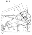
- a lever 7 is also supported with one arm, in the operating position of which the axes of the fulcrum 6 and the drive motor 3 lie on a straight line 22 with the common axis 8 of the large pulley 9 and the countershaft sprocket 10.
- the common axis 8 is arranged in the vicinity of the free end 11 of the single-arm lever 7.
- the countershaft sprocket 10 is pulled into the drive belt 14 for the laundry drum 4 by this spring 12. As a result, the belt 14 remains under tension without any adjustment being required.
- the drum cross-sectional circular area 15 represents the drum pulley which is wrapped by the belt 14 and which is automatically in the same plane as the countershaft sprocket 10.
- the lever 7 is stretched by a compression spring 16 which is guided in a double-walled sleeve 17 so that the large pulley 9 has its lay belt 18 between them and the motor pinion 19 stretches.
- the countershaft belt 18 remains constantly tensioned without adjustment.
- the tension of the belts 14 and 18 is determined in part by the geometry of the countershaft parts and essentially by the tensioning forces of the springs 12 and 16.
- the rotational forces required for transmission from the motor to the large pulley 9 and from the countershaft sprocket 10 to the casing of the drum 4 determine the tension required for the belts 18 and 14.
- the tension for belt 18 is represented by vector F18 and the tension for belt 14 is represented by vector F14.
- the spring force F12 is broken down into the vector F2, which is the corresponding normal force on the straight line 22 at the point of application 20 of the point of intersection of the imaginary axis of the spring 12 and the straight line 22, and the vector F19, which ultimately results from the existing triangle of forces at the angle can be calculated.
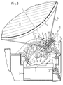
- FIG. 3 shows another embodiment for a drive device according to the invention.
- the one-armed lever 23 is not resiliently mounted at its pivot point 6; the lever 23 is rigid in itself. However, in the vicinity of its lever end 11 it has a link guide 24, which shows the central axis in the operating position of the lever 23 approximately on the axis of the motor 3.
- the link guide 24 receives a carriage 25 on which the bearing for the large pulley 9 and for the countershaft sprocket 10 is fastened. With this slide 25, the countershaft bearing can therefore be moved back and forth in the direction of the central axis of the link guide 24.
- the carriage 25 has at its end 26 protruding from the lever 23 a counter bearing bridge 27 for a compression spring 28 which is supported on a bearing plate 29 of the lever 23.
- the compression spring 28 therefore pulls the large pulley 9 over the countershaft bearing and the slide 25 into the belt 18.
- the countershaft sprocket 10 is pulled into the belt 14 by the tension spring 12 at the end 11 of the lever 23.
- FIG. 3 illustrated embodiment other spring tensions.
- the basic structure of the drive device according to the invention and the calculation process for the spring forces are, however, of the same type.
Abstract
Description
Die Erfindung geht aus von einer Antriebseinrichtung für einen Haushalt-Wäschetrockner mit einer wenigstens annähernd horizontal drehbar gelagerten Wäschetrommel, die mittels eines um ihren Trommelmantel geschlungenen Antriebsriemens von einem Vorgelege-Ritzel in einer Richtung oder reversierend antreibbar ist, das mit einer großen Rienenscheibe drehfest verbunden und auf einer gemeinsamen Achse gelagert ist und seinerseits über einen Vorgelege-Riemen vom Motor-Ritzel eines elektrischen Antriebsmotors angetrieben wird.The invention relates to a drive device for a household tumble dryer with an at least approximately horizontally rotatably mounted laundry drum, which can be driven in one direction or reversibly by a countershaft sprocket by means of a drive belt wrapped around its drum jacket, which is connected in a rotationally fixed manner to a large pulley and is mounted on a common axis and in turn is driven by the motor pinion of an electric drive motor via a countershaft belt.
Eine derartige Antriebseinrichtung ist aus dem US-Patent 3 382 587 bekannt. Darin sind die Abstände zwischen den Achsen des Motor-Ritzels und des Vorgeleges sowie zwischen diesem und der Wäschetrommel fest eingestellt. Daher müssen bei der Montage der Antriebseinrichtung der Vorgelege-Riemen und der Trommel-Antriebsriemen mittels einer Justiereinrichtung gespannt werden; denn die Einbau-Abmessungen und die Längenäbmessungen der Riemen sind toleranzbehaftet. Zum Zwecke der Einhaltung der für die erforderliche Kraftübertragung gewünschten Riemenspannungen müssen die Toleranzen durch Justage ausgeglichen werden. Außerdem unterliegen die Riemen über eine längere Lebensdauer einer bleibenden Längendehnung, die bei fest eingestellten Achsabständen zur Verminderung der Riemenspannungen und damit zur Herabsetzung der übertragbaren Kräfte sowie letztendlich zur Zerstörung der Riemen führt.Such a drive device is known from US Pat. No. 3,382,587. The distances between the axles of the motor pinion and the countershaft as well as between this and the washing drum are fixed. Therefore, the countershaft belt and the drum drive belt must be tensioned by means of an adjusting device during the assembly of the drive device; because the installation dimensions and the length dimensions of the belts are subject to tolerance. For the purpose of maintaining the belt tension required for the required power transmission, the tolerances must be adjusted be balanced. In addition, the belts are subject to permanent elongation over a longer service life, which at fixed center distances reduces the belt tension and thus reduces the transmissible forces and ultimately destroys the belt.
Zur Vermeidung solcher Längenunterschiede sind schon Spannrollen eingesetzt worden (DE-OS 22 07 372), die mittels eines oder mehrerer federbelasteter Hebel auf der jeweiligen Riemen-Rückseite lasten. Abgesehen von einem solchen Zusatz-Aufwand und der im Vergleich zur Ritzelumfassung gegenläufigen Umlenkung entstehenden Walkarbeit haben die meisten nicht bereits zu komplizierten Spannrollen eine unerwünschte Eigenschaft: Sie führen zum Auflaufen des Antriebsritzels bzw. der Spannrolle auf das zulaufende Riementrum und verringern dadurch die übertragbaren Kräfte.To avoid such differences in length, tensioning rollers have already been used (DE-OS 22 07 372), which are loaded by means of one or more spring-loaded levers on the respective rear of the belt. Apart from such an additional effort and the flexing work that arises in the opposite direction to the pinion encirclement, most of the tensioning pulleys that are not too complicated already have an undesirable property: they lead to the drive pinion or tensioning pulley running onto the incoming belt drum and thereby reduce the transferable forces.
Der Erfindung liegt die Aufgabe zugrunde, bei einer eingangs definierten Antriebseinrichtung die vorstehenden Nachteile zu vermeiden und eine justagefreie Konstruktion zu schaffen, die auch nach längerer Lebensdauer der Antriebsriemen ohne Verlust der übertragbaren Kräfte nicht nachgespannt werden muß.The invention has for its object to avoid the above disadvantages in a drive device defined at the outset and to provide an adjustment-free construction which does not have to be retightened without loss of the transferable forces even after a longer service life of the drive belt.
Erfindungsgemäß wird diese Aufgabe dadurch gelöst, daß die gemeinsame Achse achsparallel beweglich geführt ist und sowohl in Beziehung auf die Achse des Motor-Ritzels wie auch in Beziehung auf die Trommelachse im Sinne einer Abstandsvergrößerung federbelastet ist. Eine solche Ausbildung der Antriebseinrichtung gleicht im System steckende Toleranzen, wie auch zusätzliche Längenänderungstoleranzen der Riemen beim fortgeschrittenen Gebrauch des Wäschetrockners automatisch aus. Dabei kann ein sonst bei der Montage vorgesehener Arbeitsgang entfallen, durch den die Achsabstände für die Antriebsriemen besonders justiert werden mußten. Durch die Unempfindlichkeit der erfindungsgemäßen Antriebseinrichtung gegen langfristige Längenänderungstoleranzen der Riemen entfällt auch die Zahl der sonst nötigen Kundendiensteinsätze zum Nachspannen der Riemen.According to the invention, this object is achieved in that the common axis is guided in an axially parallel manner and is spring-loaded both in relation to the axis of the motor pinion and in relation to the drum axis in the sense of increasing the distance. Such a design of the drive device automatically compensates for tolerances in the system, as well as additional length change tolerances for the belts in the advanced use of the clothes dryer out. In this case, an operation which is otherwise provided for during assembly can be omitted, as a result of which the center distances for the drive belts had to be particularly adjusted. Due to the insensitivity of the drive device according to the invention to long-term length change tolerances of the belts, the number of service calls that are otherwise necessary for retensioning the belts is also eliminated.
Gemäß einer vorteilhaften Ausbildung der Erfindung befindet sich die gemeinsame Achse in der Nähe des freien Endes eines einarmig gelagerten Hebels. Die Zusammenlegung der Beweglichkeit der gemeinsamen Achse in beiden genannten Beziehungen auf einen einarmig gelagerten Hebel vereinfacht die Konstruktion gegenüber bekannten Vorschlägen und gewinnt zusätzlich Sicherheit bei der Einhaltung der Übertragungskräfte.According to an advantageous embodiment of the invention, the common axis is located near the free end of a lever with one arm. The combination of the mobility of the common axis in both of the above-mentioned relationships on a single-arm lever simplifies the design compared to known proposals and additionally gains security in compliance with the transmission forces.
Für die Einhaltung einer definierten Spannkraft im Vorgelege-Riemen ist eine Weiterbildung der Erfindung vorteilhaft, bei der in ordnungsgemäßer Betriebssituation der Drehpunkt des Hebels und die gemeinsame Achse zusammen mit dem Drehpunkt des Motor-Ritzels zumindest angenähert auf einer Geraden liegen.To maintain a defined tensioning force in the countershaft belt, a further development of the invention is advantageous in which, in the correct operating situation, the pivot point of the lever and the common axis together with the pivot point of the motor pinion lie at least approximately on a straight line.
Die Einfachheit der Konstruktion mit der Anordnung auf einem einarmig gelagerten Hebel zeigt sich insbesondere darin, daß die Federbelastung in Beziehung auf die Trommelachse durch eine zwischen einem festen Gehäuse-Teil und dem äußersten freien Ende des Hebels eingespannte Zugfeder dargestellt ist.The simplicity of the construction with the arrangement on a single-arm lever is particularly evident in the fact that the spring load in relation to the drum axis is represented by a tension spring clamped between a fixed housing part and the extreme free end of the lever.
Die Einfachheit der Konstruktion bei der Federbelastung des Vorgelege-Riemens zeigt sich in zwei Alternativen, bei denen die Federbelastung in Beziehung auf die Achse des Motor-Ritzels einmal durch eine zwischen dem Drehpunkt des Hebels und dem Hebelarm eingespannte Druckfeder und andererseits durch eine zwischen dem Drehpunkt der großen Riemenscheibe und einer am Hebelarm festen Gegenlage eingespannten Druckfeder dargestellt ist. Zwar erscheint hierdurch die Konstruktion des Hebelarms kompliziert. Da dieser aber aus einem Aluminium-Druckgußteil besteht, beschränkt sich die Kompliziertheit auf die einmalige Herstellung des Gußwerkzeugs.The simplicity of the design in the spring loading of the countershaft belt can be seen in two alternatives the spring load in relation to the axis of the motor pinion is represented once by a compression spring clamped between the pivot point of the lever and the lever arm and on the other hand by a compression spring clamped between the pivot point of the large pulley and a counterpart fixed to the lever arm. This makes the construction of the lever arm complicated. However, since this consists of an aluminum die-cast part, the complexity is limited to the one-time production of the casting tool.
Ein einziges zusätzliches Bauteil wird bei einer Weiterbildung der solchermaßen ausgestalteten Erfindung dadurch benötigt, daß der Drehpunkt für die große Riemenscheibe und das Vorgelege-Ritzel an einem mindestens annähernd in Richtung der Achse des Motor-Ritzels am Hebel geführten Schlitten angebracht ist.A single additional component is required in a development of the invention designed in such a way that the fulcrum for the large pulley and the countershaft sprocket is attached to a slide guided at least approximately in the direction of the axis of the motor pinion on the lever.
Vorteilhafterweise weist der Schlitten eine Kammer mit einer entfernt vom Drehpunkt angebrachten Federstütze für die Druckfeder auf, deren feste Gegenlage am Hebel sich nahe einem in der Führung des Schlittens angebrachten Langloch für die Durchdringung des Hebels mit der Vorgelege-Welle befindet.Advantageously, the slide has a chamber with a spring support for the compression spring, which is located at a distance from the fulcrum and whose fixed counterpart on the lever is close to an elongated hole in the guide of the slide for penetrating the lever with the countershaft.
Anhand zweier in der Zeichnung dargestellter Ausführungsbeispiele ist die Erfindung nachstehend erläutert. Es zeigen
- Fig. 1
- eine erfindungsgemäße Antriebseinrichtung mit einem einseitig gelagerten Hebel, der an seinem Lagerpunkt längsverschieblich unterbrochen ist und mit einer Druckfeder zum Spannen des Vorgelege-Riemens versehen ist,
- Fig. 2
- eine das Vorgelege gemäß Fig. 1 betreffende Einzelheit zur Erläuterung der Kraftverhältnisse an der gemeinsamen Achse und
- Fig. 3
- eine anders als in Fig. 1 und 2 ausgebildete Antriebseinrichtung, bei der die gemeinsame Achse auf einem im Hebel geführten und federbelasteten Schlitten angeordnet ist.
- Fig. 1
- a drive device according to the invention with a lever mounted on one side, which is displaceably interrupted at its bearing point and is provided with a compression spring for tensioning the countershaft belt,
- Fig. 2
- a detail relating to the transmission according to FIG. 1 to explain the force relationships on the common axis and
- Fig. 3
- a differently than in Fig. 1 and 2 designed drive device, in which the common axis is arranged on a guided in the lever and spring-loaded carriage.
Im unteren Bereich des Gehäuses 1 eines Wäschetrockners ist der Sockel 2 einer Bodengruppe eingebaut. Darin ruht der Antriebsmotor 3 für die Wäschetrommel 4, die ihrerseits an einem nicht dargestellten, entfernt vom Sockel 2 angeordneten Gehäusebauteil auf der Achse 5 drehbar gelagert ist. Im Drehpunkt 6 des Sockelteils 2 ist außerdem ein Hebel 7 einarmig gelagert, in dessen Betriebsposition die Achsen des Drehpunkts 6 und des Antriebsmotors 3 mit der gemeinsamen Achse 8 der großen Riemenscheibe 9 und des Vorgelege-Ritzels 10 auf einer Geraden 22 liegen. Die gemeinsame Achse 8 ist dabei in der Nähe des freien Endes 11 des einarmig gelagerten Hebels 7 angeordnet. Am freien Ende 11 des Hebels 7 greift eine Zugfeder 12 an, deren anderes Ende in einen Haken 13 des Sockelteils 2 eingehängt ist. Durch diese Feder 12 wird das Vorgelege-Ritzel 10 in den Antriebsriemen 14 für die Wäschetrommel 4 gezogen. Dadurch bleibt der Riemen 14 ständig gespannt, ohne daß es irgendeiner Justage bedürfte. Die Trommelquerschnitts-Kreisfläche 15 stellt die vom Riemen 14 umschlungene, automatisch in derselben Ebene wie das Vorgelege-Ritzel 10 liegende Trommelscheibe dar.The
Der Hebel 7 wird durch eine Druckfeder 16, die in einer doppelwandigen Hülse 17 geführt ist, so gestreckt, daß die große Riemenscheibe 9 ihren Vorgelege-Riemen 18 zwischen sich und dem Motor-Ritzel 19 dehnt. Dadurch bleibt auch der Vorgelege-Riemen 18 ohne Justage ständig gespannt.The lever 7 is stretched by a
Die Spannung der Riemen 14 und 18 wird zum Teil durch die Geometrie der Vorgelege-Teile und in wesentlichen durch die Spannkräfte der Federn 12 und 16 bestimmt.The tension of the
Zur Erläuterung der Kraftverhältnisse ist der Vorlegebereich aus Fig. 1 in Fig. 2 vergrößert dargestellt. Die zur Übertragung notwendigen Drehkräfte vom Motor auf die große Riemenscheibe 9 und vom Vorgelege-Ritzel 10 auf den Mantel der Trommel 4 legen die jeweils erforderliche Spannung für die Riemen 18 und 14 fest. Die Spannung für den Riemen 18 wird durch den Vektor F18 und die Spannung für den Riemen 14 durch den Vektor F14 dargestellt. Aus diesen beiden bekannten Größen sowie aus dem Abstand LT vom Drehpunkt 6 des Hebels 7 zum fiktiven Angriffspunkt 20 der Kraft F12 der Zugfeder 12 an der Geraden 22 und dem Abstand LV vom Drehpunkt 6 zum Angriffspunkt der Spannung des Riemens 14 in der gemeinsamen Achse 8 des Vorgeleges lassen sich die notwendigen Federkräfte wie folgt errechnen:To explain the force relationships, the feed area from FIG. 1 is shown enlarged in FIG. 2. The rotational forces required for transmission from the motor to the large pulley 9 and from the
An der Achse 8 greift die Spannkraft F14 des Riemens 14 an, die genau auf der Verbindungslinie 21 zwischen der Achse 8 und der Achse 5 der Trommel 4 liegt. Zerlegt man diesen Kraftvektor F14 in die Normalkräfte F1 und F4, dann läßt sich ein weiterer in Richtung auf den Drehpunkt 6 des Vorgelege-Hebels zeigender Vektor F1 ermitteln. Dieser Vektor ergibt sich aus der nachstehenden Formel:![]()
![]()
Die Federkraft F12 zerlegt sich in den Vektor F2, das ist die entsprechende Normalkraft auf die Gerade 22 am Angriffspunkt 20 des Kreuzungspunktes der gedachten Achse der Feder 12 mit der Geraden 22, und den Vektor F19, der sich schließlich aus dem vorhandenen Kräftedreieck unter den Winkel errechnen läßt. Darin ist![]()
![]()
![]()
![]()
![]()
![]()
![]()
![]()
![]()
![]()
![]()
![]()
Durch völlig andersartige Abmessungen gegenüber den Ausführungsbeispiel nach Fig. 1 und 2 ergeben sich bei dem in Fig. 3 dargestellten Ausführungsbeispiel andere Federspannungen. Der grundsätzliche Aufbau der erfindungsgemäßen Antriebseinrichtung und der Berechnungsgang für die Federkräfte sind aber gleichartig.Due to completely different dimensions compared to the exemplary embodiment according to FIGS. 1 and 2, the result shown in FIG. 3 illustrated embodiment other spring tensions. The basic structure of the drive device according to the invention and the calculation process for the spring forces are, however, of the same type.
Claims (8)
Applications Claiming Priority (2)
| Application Number | Priority Date | Filing Date | Title |
|---|---|---|---|
| DE4438425 | 1994-10-27 | ||
| DE4438425A DE4438425B4 (en) | 1994-10-27 | 1994-10-27 | Drive device for a household tumble dryer |
Publications (2)
| Publication Number | Publication Date |
|---|---|
| EP0709515A1 true EP0709515A1 (en) | 1996-05-01 |
| EP0709515B1 EP0709515B1 (en) | 2001-05-23 |
Family
ID=6531860
Family Applications (1)
| Application Number | Title | Priority Date | Filing Date |
|---|---|---|---|
| EP95112317A Expired - Lifetime EP0709515B1 (en) | 1994-10-27 | 1995-08-04 | Driving device for domestic laundry drier |
Country Status (3)
| Country | Link |
|---|---|
| US (1) | US5694795A (en) |
| EP (1) | EP0709515B1 (en) |
| DE (2) | DE4438425B4 (en) |
Cited By (3)
| Publication number | Priority date | Publication date | Assignee | Title |
|---|---|---|---|---|
| EP0903433A2 (en) * | 1997-09-18 | 1999-03-24 | CANDY S.p.A. | An improved belt transmission, particularly for laundry driers and washing machines |
| WO2001020071A1 (en) * | 1999-09-15 | 2001-03-22 | Senkingwerk Gmbh | Drum drive |
| DE102006061526A1 (en) | 2006-12-27 | 2008-07-03 | BSH Bosch und Siemens Hausgeräte GmbH | Drive unit of domestic spin dryer for drying laundry has drive motor fixed in dryer housing and transmission on turning arm with sprocket fixed to belt pulley |
Families Citing this family (6)
| Publication number | Priority date | Publication date | Assignee | Title |
|---|---|---|---|---|
| IT1289377B1 (en) * | 1996-05-22 | 1998-10-02 | Electrolux Zanussi Elettrodome | DEVICE FOR MOUNTING THE MOTOR IN A WASHING MACHINE |
| DE19728068B4 (en) * | 1997-07-01 | 2006-08-17 | BSH Bosch und Siemens Hausgeräte GmbH | clothes dryer |
| US5976043A (en) * | 1997-08-18 | 1999-11-02 | Hise; Neil R. | Apparatus for increasing wear life of machine members |
| US7168274B2 (en) * | 2003-05-05 | 2007-01-30 | American Dryer Corporation | Combination washer/dryer having common heat source |
| US7204774B2 (en) * | 2004-05-17 | 2007-04-17 | Emerson Electric Co. | One-piece drive pulley and belt guide |
| CN110594373B (en) * | 2019-08-13 | 2024-02-13 | 上海海尔洗涤电器有限公司 | Belt tensioning mechanism, clothes dryer and belt tensioning method of clothes dryer |
Citations (6)
| Publication number | Priority date | Publication date | Assignee | Title |
|---|---|---|---|---|
| US2506516A (en) | 1945-09-19 | 1950-05-02 | Hamilton Mfg Co | Laundry drier |
| US2716820A (en) | 1952-11-26 | 1955-09-06 | Temco Inc | Drying apparatus |
| US2814886A (en) * | 1954-12-27 | 1957-12-03 | Paul L Fowler | Clothes dryer |
| US3066422A (en) * | 1959-01-07 | 1962-12-04 | Blackstone Corp | Clothes driers |
| US3382587A (en) | 1966-09-06 | 1968-05-14 | Mc Graw Edison Co | Clothes conditioning-drying machine |
| DE2207372A1 (en) | 1972-02-17 | 1973-08-23 | Miele & Cie | CLOTHING DRYER WITH CIRCULATING WASHING DRUM |
Family Cites Families (1)
| Publication number | Priority date | Publication date | Assignee | Title |
|---|---|---|---|---|
| US2994216A (en) * | 1959-09-02 | 1961-08-01 | Westinghouse Electric Corp | Laundry apparatus |
-
1994
- 1994-10-27 DE DE4438425A patent/DE4438425B4/en not_active Expired - Fee Related
-
1995
- 1995-08-04 EP EP95112317A patent/EP0709515B1/en not_active Expired - Lifetime
- 1995-08-04 DE DE59509281T patent/DE59509281D1/en not_active Expired - Fee Related
- 1995-10-27 US US08/549,058 patent/US5694795A/en not_active Expired - Fee Related
Patent Citations (6)
| Publication number | Priority date | Publication date | Assignee | Title |
|---|---|---|---|---|
| US2506516A (en) | 1945-09-19 | 1950-05-02 | Hamilton Mfg Co | Laundry drier |
| US2716820A (en) | 1952-11-26 | 1955-09-06 | Temco Inc | Drying apparatus |
| US2814886A (en) * | 1954-12-27 | 1957-12-03 | Paul L Fowler | Clothes dryer |
| US3066422A (en) * | 1959-01-07 | 1962-12-04 | Blackstone Corp | Clothes driers |
| US3382587A (en) | 1966-09-06 | 1968-05-14 | Mc Graw Edison Co | Clothes conditioning-drying machine |
| DE2207372A1 (en) | 1972-02-17 | 1973-08-23 | Miele & Cie | CLOTHING DRYER WITH CIRCULATING WASHING DRUM |
Cited By (5)
| Publication number | Priority date | Publication date | Assignee | Title |
|---|---|---|---|---|
| EP0903433A2 (en) * | 1997-09-18 | 1999-03-24 | CANDY S.p.A. | An improved belt transmission, particularly for laundry driers and washing machines |
| EP0903433A3 (en) * | 1997-09-18 | 1999-07-21 | CANDY S.p.A. | An improved belt transmission, particularly for laundry driers and washing machines |
| WO2001020071A1 (en) * | 1999-09-15 | 2001-03-22 | Senkingwerk Gmbh | Drum drive |
| DE102006061526A1 (en) | 2006-12-27 | 2008-07-03 | BSH Bosch und Siemens Hausgeräte GmbH | Drive unit of domestic spin dryer for drying laundry has drive motor fixed in dryer housing and transmission on turning arm with sprocket fixed to belt pulley |
| WO2008080826A1 (en) * | 2006-12-27 | 2008-07-10 | BSH Bosch und Siemens Hausgeräte GmbH | Drive unit for domestic clothes dryer |
Also Published As
| Publication number | Publication date |
|---|---|
| DE59509281D1 (en) | 2001-06-28 |
| DE4438425B4 (en) | 2006-10-26 |
| DE4438425A1 (en) | 1996-05-02 |
| EP0709515B1 (en) | 2001-05-23 |
| US5694795A (en) | 1997-12-09 |
Similar Documents
| Publication | Publication Date | Title |
|---|---|---|
| EP1185804B1 (en) | Internal combustion engine belt drive | |
| DE19619087A1 (en) | Fastening device | |
| DE3743889A1 (en) | LIFTING MACHINE | |
| DE3340557C2 (en) | ||
| EP0709515A1 (en) | Driving device for domestic laundry drier | |
| DE3522591C2 (en) | ||
| DE19847855C2 (en) | Multi-joint robot | |
| DE102005043891B4 (en) | Apparatus for reciprocating a wire | |
| DE3141384A1 (en) | DRIVE SYSTEM | |
| DE19636705C2 (en) | Motor unit for a clothes dryer | |
| DE102019121103A1 (en) | Screen lift system for flat screens for arrangement in furniture or built-in furniture | |
| DE4242937C1 (en) | Drive for a curved sliding door | |
| DE4225770C2 (en) | Household clothes dryer with a belt tensioner | |
| DE10331949B3 (en) | A method for maintaining the belt tension in a domestic washing and drying machine has a combined drum motor and fan motor assembly which is pivoted and tensioned by a spring | |
| DE202005013076U1 (en) | Window-raising mechanism for vehicle door includes motor-driven cord passed over pulleys with limited freedom of movement and resilient attachment | |
| CH428304A (en) | Device for shaking branches | |
| WO2008080826A1 (en) | Drive unit for domestic clothes dryer | |
| DE19517372A1 (en) | Drum tumble dryer with drive belt and tensioner | |
| DE3728766C1 (en) | Test chamber | |
| DE3924321C2 (en) | Device for fastening a window regulator motor | |
| EP1811075A1 (en) | Clamping device for a gear and pinion drive of a domestic clothes dryer | |
| CH673133A5 (en) | Sun blind operating drive - uses electrically operated drive wheels controlling drive chains for opposite ends of horizontal front bar | |
| AT220548B (en) | Dung loader | |
| CH691131A5 (en) | Roller shutter for window with electromagnetic drive arrangement; has lifting shaft box connected by two elastomer elements to integrated drive casing for electric motor | |
| DE2410233C3 (en) | Device for moving a ring rail of a spinning machine |
Legal Events
| Date | Code | Title | Description |
|---|---|---|---|
| PUAI | Public reference made under article 153(3) epc to a published international application that has entered the european phase |
Free format text: ORIGINAL CODE: 0009012 |
|
| AK | Designated contracting states |
Kind code of ref document: A1 Designated state(s): CH DE FR GB LI NL SE |
|
| 17P | Request for examination filed |
Effective date: 19961024 |
|
| RAP1 | Party data changed (applicant data changed or rights of an application transferred) |
Owner name: BSH BOSCH UND SIEMENS HAUSGERAETE GMBH |
|
| 17Q | First examination report despatched |
Effective date: 19990201 |
|
| GRAG | Despatch of communication of intention to grant |
Free format text: ORIGINAL CODE: EPIDOS AGRA |
|
| GRAG | Despatch of communication of intention to grant |
Free format text: ORIGINAL CODE: EPIDOS AGRA |
|
| GRAH | Despatch of communication of intention to grant a patent |
Free format text: ORIGINAL CODE: EPIDOS IGRA |
|
| GRAH | Despatch of communication of intention to grant a patent |
Free format text: ORIGINAL CODE: EPIDOS IGRA |
|
| GRAA | (expected) grant |
Free format text: ORIGINAL CODE: 0009210 |
|
| AK | Designated contracting states |
Kind code of ref document: B1 Designated state(s): CH DE FR GB LI NL SE |
|
| REG | Reference to a national code |
Ref country code: CH Ref legal event code: NV Representative=s name: ISLER & PEDRAZZINI AG Ref country code: CH Ref legal event code: EP |
|
| GBT | Gb: translation of ep patent filed (gb section 77(6)(a)/1977) |
Effective date: 20010523 |
|
| REF | Corresponds to: |
Ref document number: 59509281 Country of ref document: DE Date of ref document: 20010628 |
|
| ET | Fr: translation filed | ||
| REG | Reference to a national code |
Ref country code: GB Ref legal event code: IF02 |
|
| PLBE | No opposition filed within time limit |
Free format text: ORIGINAL CODE: 0009261 |
|
| STAA | Information on the status of an ep patent application or granted ep patent |
Free format text: STATUS: NO OPPOSITION FILED WITHIN TIME LIMIT |
|
| 26N | No opposition filed | ||
| PGFP | Annual fee paid to national office [announced via postgrant information from national office to epo] |
Ref country code: NL Payment date: 20050818 Year of fee payment: 11 |
|
| PGFP | Annual fee paid to national office [announced via postgrant information from national office to epo] |
Ref country code: SE Payment date: 20050824 Year of fee payment: 11 |
|
| PG25 | Lapsed in a contracting state [announced via postgrant information from national office to epo] |
Ref country code: SE Free format text: LAPSE BECAUSE OF NON-PAYMENT OF DUE FEES Effective date: 20060805 |
|
| PG25 | Lapsed in a contracting state [announced via postgrant information from national office to epo] |
Ref country code: NL Free format text: LAPSE BECAUSE OF NON-PAYMENT OF DUE FEES Effective date: 20070301 |
|
| EUG | Se: european patent has lapsed | ||
| NLV4 | Nl: lapsed or anulled due to non-payment of the annual fee |
Effective date: 20070301 |
|
| REG | Reference to a national code |
Ref country code: CH Ref legal event code: PCAR Free format text: ISLER & PEDRAZZINI AG;POSTFACH 1772;8027 ZUERICH (CH) |
|
| PGFP | Annual fee paid to national office [announced via postgrant information from national office to epo] |
Ref country code: DE Payment date: 20080831 Year of fee payment: 14 Ref country code: CH Payment date: 20080825 Year of fee payment: 14 |
|
| PGFP | Annual fee paid to national office [announced via postgrant information from national office to epo] |
Ref country code: FR Payment date: 20080818 Year of fee payment: 14 |
|
| PGFP | Annual fee paid to national office [announced via postgrant information from national office to epo] |
Ref country code: GB Payment date: 20080822 Year of fee payment: 14 |
|
| REG | Reference to a national code |
Ref country code: CH Ref legal event code: PL |
|
| GBPC | Gb: european patent ceased through non-payment of renewal fee |
Effective date: 20090804 |
|
| PG25 | Lapsed in a contracting state [announced via postgrant information from national office to epo] |
Ref country code: LI Free format text: LAPSE BECAUSE OF NON-PAYMENT OF DUE FEES Effective date: 20090831 Ref country code: CH Free format text: LAPSE BECAUSE OF NON-PAYMENT OF DUE FEES Effective date: 20090831 |
|
| REG | Reference to a national code |
Ref country code: FR Ref legal event code: ST Effective date: 20100430 |
|
| PG25 | Lapsed in a contracting state [announced via postgrant information from national office to epo] |
Ref country code: FR Free format text: LAPSE BECAUSE OF NON-PAYMENT OF DUE FEES Effective date: 20090831 Ref country code: DE Free format text: LAPSE BECAUSE OF NON-PAYMENT OF DUE FEES Effective date: 20100302 |
|
| PG25 | Lapsed in a contracting state [announced via postgrant information from national office to epo] |
Ref country code: GB Free format text: LAPSE BECAUSE OF NON-PAYMENT OF DUE FEES Effective date: 20090804 |