EP0708390A2 - Supporting method and system for process operation - Google Patents
Supporting method and system for process operation Download PDFInfo
- Publication number
- EP0708390A2 EP0708390A2 EP95118768A EP95118768A EP0708390A2 EP 0708390 A2 EP0708390 A2 EP 0708390A2 EP 95118768 A EP95118768 A EP 95118768A EP 95118768 A EP95118768 A EP 95118768A EP 0708390 A2 EP0708390 A2 EP 0708390A2
- Authority
- EP
- European Patent Office
- Prior art keywords
- input
- layer
- variable
- knowledge
- output
- Prior art date
- Legal status (The legal status is an assumption and is not a legal conclusion. Google has not performed a legal analysis and makes no representation as to the accuracy of the status listed.)
- Granted
Links
Images


Classifications
-
- G—PHYSICS
- G05—CONTROLLING; REGULATING
- G05B—CONTROL OR REGULATING SYSTEMS IN GENERAL; FUNCTIONAL ELEMENTS OF SUCH SYSTEMS; MONITORING OR TESTING ARRANGEMENTS FOR SUCH SYSTEMS OR ELEMENTS
- G05B13/00—Adaptive control systems, i.e. systems automatically adjusting themselves to have a performance which is optimum according to some preassigned criterion
- G05B13/02—Adaptive control systems, i.e. systems automatically adjusting themselves to have a performance which is optimum according to some preassigned criterion electric
- G05B13/0265—Adaptive control systems, i.e. systems automatically adjusting themselves to have a performance which is optimum according to some preassigned criterion electric the criterion being a learning criterion
- G05B13/027—Adaptive control systems, i.e. systems automatically adjusting themselves to have a performance which is optimum according to some preassigned criterion electric the criterion being a learning criterion using neural networks only
-
- C—CHEMISTRY; METALLURGY
- C02—TREATMENT OF WATER, WASTE WATER, SEWAGE, OR SLUDGE
- C02F—TREATMENT OF WATER, WASTE WATER, SEWAGE, OR SLUDGE
- C02F1/00—Treatment of water, waste water, or sewage
- C02F1/008—Control or steering systems not provided for elsewhere in subclass C02F
-
- C—CHEMISTRY; METALLURGY
- C02—TREATMENT OF WATER, WASTE WATER, SEWAGE, OR SLUDGE
- C02F—TREATMENT OF WATER, WASTE WATER, SEWAGE, OR SLUDGE
- C02F1/00—Treatment of water, waste water, or sewage
- C02F1/52—Treatment of water, waste water, or sewage by flocculation or precipitation of suspended impurities
- C02F1/5236—Treatment of water, waste water, or sewage by flocculation or precipitation of suspended impurities using inorganic agents
- C02F1/5245—Treatment of water, waste water, or sewage by flocculation or precipitation of suspended impurities using inorganic agents using basic salts, e.g. of aluminium and iron
-
- C—CHEMISTRY; METALLURGY
- C02—TREATMENT OF WATER, WASTE WATER, SEWAGE, OR SLUDGE
- C02F—TREATMENT OF WATER, WASTE WATER, SEWAGE, OR SLUDGE
- C02F1/00—Treatment of water, waste water, or sewage
- C02F1/72—Treatment of water, waste water, or sewage by oxidation
- C02F1/76—Treatment of water, waste water, or sewage by oxidation with halogens or compounds of halogens
-
- G—PHYSICS
- G05—CONTROLLING; REGULATING
- G05B—CONTROL OR REGULATING SYSTEMS IN GENERAL; FUNCTIONAL ELEMENTS OF SUCH SYSTEMS; MONITORING OR TESTING ARRANGEMENTS FOR SUCH SYSTEMS OR ELEMENTS
- G05B13/00—Adaptive control systems, i.e. systems automatically adjusting themselves to have a performance which is optimum according to some preassigned criterion
- G05B13/02—Adaptive control systems, i.e. systems automatically adjusting themselves to have a performance which is optimum according to some preassigned criterion electric
- G05B13/0265—Adaptive control systems, i.e. systems automatically adjusting themselves to have a performance which is optimum according to some preassigned criterion electric the criterion being a learning criterion
- G05B13/0285—Adaptive control systems, i.e. systems automatically adjusting themselves to have a performance which is optimum according to some preassigned criterion electric the criterion being a learning criterion using neural networks and fuzzy logic
-
- C—CHEMISTRY; METALLURGY
- C02—TREATMENT OF WATER, WASTE WATER, SEWAGE, OR SLUDGE
- C02F—TREATMENT OF WATER, WASTE WATER, SEWAGE, OR SLUDGE
- C02F1/00—Treatment of water, waste water, or sewage
- C02F1/66—Treatment of water, waste water, or sewage by neutralisation; pH adjustment
-
- C—CHEMISTRY; METALLURGY
- C02—TREATMENT OF WATER, WASTE WATER, SEWAGE, OR SLUDGE
- C02F—TREATMENT OF WATER, WASTE WATER, SEWAGE, OR SLUDGE
- C02F1/00—Treatment of water, waste water, or sewage
- C02F2001/007—Processes including a sedimentation step
-
- C—CHEMISTRY; METALLURGY
- C02—TREATMENT OF WATER, WASTE WATER, SEWAGE, OR SLUDGE
- C02F—TREATMENT OF WATER, WASTE WATER, SEWAGE, OR SLUDGE
- C02F2209/00—Controlling or monitoring parameters in water treatment
- C02F2209/02—Temperature
-
- C—CHEMISTRY; METALLURGY
- C02—TREATMENT OF WATER, WASTE WATER, SEWAGE, OR SLUDGE
- C02F—TREATMENT OF WATER, WASTE WATER, SEWAGE, OR SLUDGE
- C02F2209/00—Controlling or monitoring parameters in water treatment
- C02F2209/05—Conductivity or salinity
-
- C—CHEMISTRY; METALLURGY
- C02—TREATMENT OF WATER, WASTE WATER, SEWAGE, OR SLUDGE
- C02F—TREATMENT OF WATER, WASTE WATER, SEWAGE, OR SLUDGE
- C02F2209/00—Controlling or monitoring parameters in water treatment
- C02F2209/06—Controlling or monitoring parameters in water treatment pH
-
- C—CHEMISTRY; METALLURGY
- C02—TREATMENT OF WATER, WASTE WATER, SEWAGE, OR SLUDGE
- C02F—TREATMENT OF WATER, WASTE WATER, SEWAGE, OR SLUDGE
- C02F2209/00—Controlling or monitoring parameters in water treatment
- C02F2209/07—Alkalinity
-
- C—CHEMISTRY; METALLURGY
- C02—TREATMENT OF WATER, WASTE WATER, SEWAGE, OR SLUDGE
- C02F—TREATMENT OF WATER, WASTE WATER, SEWAGE, OR SLUDGE
- C02F2209/00—Controlling or monitoring parameters in water treatment
- C02F2209/11—Turbidity
-
- C—CHEMISTRY; METALLURGY
- C02—TREATMENT OF WATER, WASTE WATER, SEWAGE, OR SLUDGE
- C02F—TREATMENT OF WATER, WASTE WATER, SEWAGE, OR SLUDGE
- C02F2209/00—Controlling or monitoring parameters in water treatment
- C02F2209/29—Chlorine compounds
-
- C—CHEMISTRY; METALLURGY
- C02—TREATMENT OF WATER, WASTE WATER, SEWAGE, OR SLUDGE
- C02F—TREATMENT OF WATER, WASTE WATER, SEWAGE, OR SLUDGE
- C02F2209/00—Controlling or monitoring parameters in water treatment
- C02F2209/42—Liquid level
-
- C—CHEMISTRY; METALLURGY
- C02—TREATMENT OF WATER, WASTE WATER, SEWAGE, OR SLUDGE
- C02F—TREATMENT OF WATER, WASTE WATER, SEWAGE, OR SLUDGE
- C02F2303/00—Specific treatment goals
- C02F2303/04—Disinfection
-
- Y—GENERAL TAGGING OF NEW TECHNOLOGICAL DEVELOPMENTS; GENERAL TAGGING OF CROSS-SECTIONAL TECHNOLOGIES SPANNING OVER SEVERAL SECTIONS OF THE IPC; TECHNICAL SUBJECTS COVERED BY FORMER USPC CROSS-REFERENCE ART COLLECTIONS [XRACs] AND DIGESTS
- Y02—TECHNOLOGIES OR APPLICATIONS FOR MITIGATION OR ADAPTATION AGAINST CLIMATE CHANGE
- Y02W—CLIMATE CHANGE MITIGATION TECHNOLOGIES RELATED TO WASTEWATER TREATMENT OR WASTE MANAGEMENT
- Y02W10/00—Technologies for wastewater treatment
- Y02W10/30—Wastewater or sewage treatment systems using renewable energies
- Y02W10/37—Wastewater or sewage treatment systems using renewable energies using solar energy
-
- Y—GENERAL TAGGING OF NEW TECHNOLOGICAL DEVELOPMENTS; GENERAL TAGGING OF CROSS-SECTIONAL TECHNOLOGIES SPANNING OVER SEVERAL SECTIONS OF THE IPC; TECHNICAL SUBJECTS COVERED BY FORMER USPC CROSS-REFERENCE ART COLLECTIONS [XRACs] AND DIGESTS
- Y10—TECHNICAL SUBJECTS COVERED BY FORMER USPC
- Y10S—TECHNICAL SUBJECTS COVERED BY FORMER USPC CROSS-REFERENCE ART COLLECTIONS [XRACs] AND DIGESTS
- Y10S706/00—Data processing: artificial intelligence
- Y10S706/902—Application using ai with detail of the ai system
- Y10S706/903—Control
- Y10S706/906—Process plant
Abstract
Description
- The present invention relates generally to a method and a system for supporting an operation of a process wherein at least one phenomenon which varies with time is dealt with.
- Conventional methods of operation (or managing) various processes wherein at least one phenomenon which varies with time is dealt with - such as water treatment processes; river information processing processes; meteorological information processing processes; thermal, nuclear and hydraulic power generation processes; co-generation processes; chemical processes; biological processes, security/exchange information processing processes, and bank management information processing processes - are practiced using formula models which describe these processes.
- It is however impossible to convert a process into a formula model unless casualities or causal relationships among a group of variables describing the process have been made clear. On the other hand, when a logical model such as the "if then" rules is employed without using a formula model, application of such a logical model is infeasible unless a causal relationship between causes and the corresponding results have been ascertained. Needless to say, even in the case of a fuzzy method which makes combined use of a formula model and a logical model, its application is impossible unless both the models are described. A judgment and/or an operation (management) has therefore been carried out in the light of precedence or past experiences in such cases. In unusual cases or the like where neither cause nor result is known, an operator has conducted the operation on the basis of the past phenomenological history or his memory. Accordingly, it has been difficult to conduct a good operation all the time.
- Further, described generally, these methods have not yet permitted any automated modification of the model structure or elements (rule, etc.). It has hence been difficult to flexibly cope with an actual phenomenon which varies in time.
- An object of the invention is therefore to provide a method and a system for supporting an operation of a process, which can support the operation of the process in a steady state or a non-steady or abnormal state by making effective use of a past history which has not heretofore been used effectively.
- Another object of the invention is to provide a method for automatically extracting knowledge such as a causal relationship between a value of an input variable and its corresponding output variable from a learned neural circuit model.
- A process operation supporting method according to the invention is a method for supporting an operation of a process, which includes determination of a value of a control variable for a target, to be controlled, in accordance with values of time-dependent input variables so as to bring the target closer to a desired state. The method comprises the steps of providing a neuron circuit model of a hierarchical structure constructed of an input layer, at least one hidden layer and an output layer; causing the neuron circuit model to learn, out of information on a past operation history of the process, a typical pattern of values of input variables at different points in time as input signals and a value of the control variable, said control value corresponding to the typical pattern, as teacher signal; and inputting, as the values of the input variables, an unlearned pattern to the thus-learned neuron circuit model to determine its corresponding value of the control variable.
- The process operation supporting method according to the invention is, in another aspect, a method for supporting an operation of a process, which includes determination of a value of a control variable for at least one target, to be controlled, in accordance with values of time-dependent input variables such that the target can be brought into a desired state. The method comprises the steps of providing a neuron circuit model of a hierarchical structure constructed of an input layer, at least one hidden layer and an output layer; causing the neuron circuit model to sequentially learn a plurality of patterns of values of input variables, each, by using, as input signals, patterns of values of the input variables at the times of attainment of control of the target into the desired state and, as teacher signals, values of the control variable, said values corresponding to the patterns; and inputting, as the values of the input variables, a given pattern of values of the input variables to the thus-learned neuron circuit model to determine a value of the control variable for said given pattern.
- In these process operation supporting methods, a value of the control variable for a present time point can also be determined by learning plural input signals through the simultaneous use of a pattern of values of the input variables at a given time point and a pattern of values of the input variables at a time point a predetermined time interval before the given time point as input signals and also the use of a value of the control variable at the given time point as a teacher signal and then simultaneously inputting to the neuron circuit model a pattern of values of the input variables at the present time point and a pattern of values of the input variables at a time point a predetermined time interval before the present time point.
- The process operation supporting method according to the invention is, in a further aspect, a method for supporting an operation of a process, which includes determination of a value of a control variable for a target, to be controlled, in accordance with values of time-dependent input variables so as to bring the target closer to a desired state. The method comprises the steps of providing a neuron circuit model of a hierarchical structure constructed of an input layer, at least one hidden layer and an output layer; causing the neuron circuit model to learn plural input signals by simultaneously using, as the input signals, at least two patterns of a pattern of values of the input variables at a given time point, a pattern of values of the input variables at a time point a predetermined time interval before the given time point and a pattern of differences between the values of the input variables at the former time point and those at the latter time point and using a value of the control variable at the given time point as a teacher signal; and inputting patterns at a present time point, said patterns corresponding to said at least two patterns, simultaneously to the thus-learned neuron circuit model to determine a value of the control variable for the present time.
- Preferably, the operation of the process is supported by extracting causal relationships between the values of the input variables and the corresponding value of the control variable on the basis of the results of the learning by the neuron circuit model and then using the causal relationships.
- The neuron circuit model has, for example, an input layer formed of plural neuron element models, at least one hidden layer formed of plural neuron element models for receiving outputs from the neuron element models of the input layer and an output layer formed of at least one neuron element model for receiving outputs from the neuron element models of a last hidden layer. The input variables are assigned to the respective neuron element models of the input layer and the control variable is assigned to the neuron element model of the output layer. The learning is performed by controlling weight factors applied to connections between the individual neuron element models.
- Further, the network of the neuron circuit model may be modified by determining the connection strengths between the individual input variables and the individual control valuables on the basis of the results of the learning by the neuron circuit model and then using the magnitudes of the connection strengths. In this case, the connection strength between a specific input variable and a specific control variable can be defined by the sum of products of weight factors for individual routes from the neuron element model, corresponding to the specific input variable, of the input layer to the neuron element model, corresponding to the specific control variable, of the output layer via the neuron element models of the hidden layer.
- The modification of the network of the neuron circuit model can be achieved by eliminating the connection between particular neuron element models or by using a varied number of hidden layers.
- It is also possible to independently provide a neuron circuit model which has learned information on a steady-state operation history and another neuron circuit model which has learned information on a non-steady-state operation history, and in supporting the operation, to switch over the neuron circuit models depending on whether the operation is to be in a steady state or in a non-steady state.
- As an alternative, it is also possible to provide a plurality of neuron circuit models, which have learned information on different operation histories respectively, for variations of the pattern of values of the input variables, and in supporting the operation, to switch over the plurality of neuron circuit models depending on the variation of the pattern of values of the input variables.
- A knowledge extracting method according to the invention is a method for extracting as knowledge causal relationships between input variables and an output variable of a neural circuit model. The neural circuit model is of a hierarchical structure constructed of an input layer, at least one hidden layer and an output layer and having performed learning a limited number of times by determining weight factors between mutually-connected neuron element models in different layers of the input layer, hidden layer and output layer. With respect to plural routes extending from a neuron element model, corresponding to a particular input variable, of the input layer to a neuron element model, corresponding to a particular output variable, of the output layer by way of the individual element models of the hidden layer, a product of the weight factors for each of the routes is determined, and the products for the plural routes are summed, whereby the sum is employed as a measure for the determination of the causal relationship between the particular input variable and the particular output variable.
- A process operation supporting system according to the invention is a system for supporting an operation of a process, which includes determination of a value of a control variable for a target, to be controlled, in accordance with values of time-dependent input variables so as to bring the target closer to a desired state. The system comprises a processing means having a neural circuit model of a hierarchical structure constructed of an input layer, at least one hidden layer and an output layer, said neural circuit model having been allowed to learn results of an actual operation in the past by using information on the history of the past operation as input signals and a teacher signal; an input means for obtaining, from the target, input values of the input variables to be inputted to the neural circuit model; a knowledge extraction means for extracting knowledge from the learned neural circuit model; a knowledge base for accumulating the knowledge obtained by the knowledge extraction means; an inference system for obtaining process-operation-supporting information from the knowledge accumulated in the knowledge base; and a guidance means for performing guidance of the control of the target in accordance with an output from the processing means and/or an output from the inference system.
- Incidentally, the term "process" as used herein embraces various processes wherein at least one phenomenon which varies with time is dealt with. The term "operation" should be interpreted in a broad sense so that it may mean operation, management, control or the like. Further, the term "to support an operation" means, in a narrow sense, to support an operator upon operation of a process but in a broad sense, includes direct control of a process without relying upon an operator.
- The invention applies a learning function of a neural circuit model to (a) learning from information on an operation history of a process, (b) acquisition of history information as knowledge and (c) automated construction of a model describing the history information.
- In causing a neural circuit model to learn, the neural circuit model is allowed to learn only typical patterns in each of which a successful operation was performed. This makes it possible to provide the neural circuit model with decision-making ability comparable with operators having abundant experiences, whereby the neural circuit model can perform a suitable support, which conforms to the past results and precedence, in response to an actual given pattern of input values of variables. Moreover, the ability of the neural circuit model can be progressively improved in the light of reality by allowing the neural circuit model to continue learning after the initiation of an actual operation of the process. It is therefore possible to ultimately aim at a uniform and optimal operation without relying upon the experiences, ability, quality and the like of each operator.
- In some processes, the optimal value of a control variable may vary even for the same pattern of the values of the input variables depending upon whether the values of individual input variables are increasing or decreasing. With the foregoing circumstances in view, the simultaneous use of not only information on the operation history at a given time point but also information on the past operation history at a time point a predetermined time interval before the given time point or information on the differences therebetween makes it possible to suitably support an operation in compliance with variations of a process. Still more effective support of an operation is feasible by providing discrete neural circuit models which have learned information on an operation history in a steady state, information on an operation history in an abnormal state, and the like, respectively.
- In addition, there is possibility that knowledge, such as causal relationships which an operator is not aware of, may be contained in information on a past operation history. However, causal relationships between many input variables and control variables are not clear. Paying attention to the magnitudes of weight factors and the connections in a neural circuit model which has already learned, the present invention has hence made it possible to automatically extract and obtain the relationships between causes and the corresponding results. As a result, it is possible to automatically or semi-automatically put pieces of knowledge, which are contained in information on operation histories without being noticed, into a data base or a knowledge base successively. Here, the term "semi-automatically" means an interactive manner of operation by the operator. Operations of various processes in each of which at least one time-dependent phenomenon is dealt with can also be supported by such knowledge bases.
-
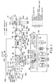
- FIG. 1 is a block diagram of one embodiment of the present invention as applied for supporting an operation of a water purifying plant;
- FIG. 2 is a flow diagram of specific procedures in the embodiment;
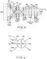
- FIG. 3 is a schematic diagram of a neural network;
- FIG. 4 is a schematic diagram of a neuron element model;
- FIG. 5 is a diagrammatical illustration of conversion of a signal by the neuron element model;
- FIG. 6 is a schematic diagram of a neural network useful for 'perception';
- FIG. 7 is a flow diagram of another embodiment of the present invention;
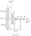
- FIG. 8 through FIG. 10 are schematic diagrams of neural networks constructed to apply the present invention to the injection of a flocculant;
- FIG. 11 through FIG. 13 are block diagrams of a further embodiment of the present invention;
- FIG. 14 is a block diagram of a still further embodiment of the present invention;
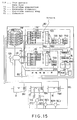
- FIG. 15 is a block diagram of a still further embodiment of the present invention;
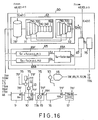
- FIG. 16 and FIG. 17 are schematic illustrations of a still further embodiment of the present invention; and
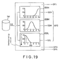
- FIG. 18 and FIG. 19 are schematic illustrations of a still further embodiment of the present invention.
- The present invention comprises the steps of: (1) causing a neural circuit model (neural processor) to learn typical patterns at different points in time out of patterns of values of multiple time-dependent input valuables, (2) supporting an operation on the basis of the results of the learning, (3) obtaining knowledge from the results of the learning and accumulating candidate knowledge, (4) diagnosing the reasonability of each candidate knowledge as knowledge, and (5) supporting the operation on the basis of the knowledge and inference. The patterns are patterns of multiple variables in past operation(s) or present operation. Although their detail description will be made below, the term "multiple variables" may include every variable which varies with time. The present invention can therefore be applied to various information processing processes or plants. Here, one embodiment of the present invention as used in the support of control of a water purifying plant will hereinafter be described with reference to FIG. 1.
- First of all, the construction and operation of the entirety of FIG. 1 will be described.
- A description will firstly be made of the flow of the water purifying plant. In FIG. 1, raw water derived from a river, lake or pond (not shown) is introduced into a receiving
basin 9. The raw water is then guided from the receivingbasin 9 to a high-speed mixing basin 10, where a flocculant (polychlorinated aluminum, aluminum sulfate or the like) in a liquid form is injected by aflocculant feed pump 12A from a flocculant tank 11A. To promote formation of flocs, an alkali agent such as calcium hydroxide or sodium carbonate is also injected by an alkaliagent feed pump 12B from analkali agent tank 11B. Inside the high-speed mixing basin 10, astirring blade 14 is driven by astirrer 13 so that fine particles of about 0.01 mm floating in the raw water are converted into microflocs of about 0.1 mm. The water is then introduced into a floc-formingbasin 15, in which the microflocs are allowed to grow into flocs. The floc-formingbasin 15 is composed ofplural basins paddles basin 16, and the supernatant is filtered in thefiltering basin 17. From awashing water tank 18, back washing water is intermittently jetted into thefiltering basin 17 by apump 19, whereby a filter bed is washed. Filtered water is temporarily stored in apurified water basin 20 and awater distribution basin 21, and is then delivered by apump 22 to individual customers by way of a distributingpipe network 24.Valves chlorine feeder 26 at suitable rates into the receivingbasin 9 and purifiedwater basin 20 from achlorine tank 25. - A description will next be made of instruments. To measure the quality of raw water, the receiving
basin 9 is equipped with a measuringinstrument 5A. Measured by theinstrument 5A are water temperature, turbidity, alkalinity, pH, electrical conductivity, residual chlorine concentration, chlorine demand, water quantity, water level, and the like. The floc-formingbasin 15C is provided with an image pickup means 5B such as a marine camera. Image pickup means may also be provided, as needed, in the high-speed mixing basin 10, the floc-formingbasins basin 16. The settlingbasin 16 is provided with aturbidimeter 5C. Measured by a measuringinstrument 5D for thefiltering basin 17 include head loss, water level, turbidity, residual chlorine concentration, pH, turbidity (sic.), flow rate, and the like. The purifiedwater basin 20 andwater distribution basin 21 are provided withinstruments pipe network 24 is equipped with a measuringinstrument 5G, which measures turbidity, residual chlorine concentration, pH, flow rate, water pressure, water temperature, and so on. - Input of these measurement values to a
computer system 80 and the processing and storage of the former by and in the latter will next be described. - Data of the various measuring instruments described above are inputted to the
computer system 80. Various data obtained by the measuringinstruments input port 56A, and are stored in amemory 54 via asystem bus 52. Thememory 54 also stores various processed data which have been processed by a system processor (SP) 42. Incidentally, electrical analog signals 5BS which have been obtained from the image pickup means 5B and represent a halftone image of flocs are converted into digital signals in animage processor 40, and are then subjected to image processing. Amonitor 50 outputs the results of processing by theimage processor 40. - Here, the
image processor 40 has the function to perform various processings which the present inventors have proposed to date (for example, Japanese Patent Application No. 82952/1986), and its outline will be described hereinafter. A halftone image obtained by the image pickup means 5B is binarized and converted into a binary image. From this binary image, the area, volume, representative diameter, configuration and the like of each floc are calculated. Calculated next are characteristic quantities such as the particle size distribution, the number of flocs, statistic representative particle sizes in the distribution, the width of the distribution (standard deviation, etc.), configurational characteristics of the flocs, the quantity of the flocs formed, the brightness of the flocs, the brightness of the background, and the density of the flocs. The overall processing may be monitored using values of the measuringinstruments - Next, the construction of the
computer system 80 will be described in further detail. Connected to thesystem bus 52 are thesystem processor 42, theimage processor 40, thememory 54, a neural processor (NP) 70, aknowledge base 60A, acandidate knowledge base 60B, and aninference system 61. To the system processor (SP) 42, akeyboard 44 and adisplay 46 are connected. Input items from thekeyboard 44 include (1) operation conditions for theimage processor 40, (2) calculation conditions for theneural processor 70, and (3) operators knowledge on water quality information and image information. An additional keyboard may also be provided exclusively for the setting of the operation conditions (1) for theimage processor 40. Thesystem processor 42 systematically controls these conditions (1), (2) and (3), and controls the operation of theinference system 61 as needed. - A description will next be made of outputs from the
computer system 80. The results of processing by thecomputer system 80 are transmitted via anoutput port 56B to the flocculant feeder pump 12A, alkaliagent feeder pump 12B,stirrer 13, stirringpaddles chlorine feeder 26, pump 22,valves - The injection of a flocculant is controlled by the
flocculant feeder pump 12A, the injection of an alkali agent by the alkaliagent feeder pump 12B, high-speed stirring by thestirrer 13, low-speed stirring by the stirring paddles 17A,17B,17C, back washing by thepump 19, pre-chlorination and post-chlorination by thechlorine feeder 26, distribution flow rate and pressure by thepump 22 and thevalves - The outline of a control method will hereinafter be described. The control method can be divided into (I) a conventional control method in which relationships between pieces of measurement information or between measurement information and output information (control information) are converted into a model on the basis of the measurement information and outputs are controlled based on the model and (II) a supporting method which relies upon learning of a history. The term "controls" as used herein mean automatic operations to be performed without enquiry to the operator. Further, the term "support" means an operator guidance, and primarily indicates an operation which performs a control only when an operator's approval is obtained after reference data and an operation guidance are reported using the display 46 (or a voice generator depending on the processing).
- A description will next be made of the outline of procedures when the method (II) is performed. In the present embodiment, the support by the method (II) comprises the following five steps: (1) learning the history of various measurement information by the
neural processor 70, (2) supporting an operation based on the results of the learning, (3) extracting knowledge and candidate knowledge from the results of the learning, (4) diagnosing the reasonability of the candidate knowledge, and (5) supporting the operation based on the knowledge and inference. Here, the term "knowledge" indicates a certain rule for the correlation between a cause and a result. Knowledge includes empirical knowledge and scientific knowledge. On the other hand, the term "candidate knowledge" indicates the combination between an event A and another event B (the event B occured when the event A was satisfied). Such a particular pair of events may occur by chance, so that it may not be considered as inevitable or empirical knowledge in many instances. It cannot therefore be recognized as knowledge. However, the pair of the events can be recognized as knowledge when they occur in combination many times. These knowledge and candidate knowledge are stored in theknowledge base 60A and thecandidate knowledge base 60B, respectively. - In some instances, it is possible to use only the learning step and the supporting step.
- Specific procedures of each of the control methods will next be described. A description will first be made of the control method (I), which relies upon a model phenomenologically representing the relationships between variables. This is a conventional method and, for example, using as input variables the quality of raw water measured by the
instrument 5A (water temperature, turbidity, alkalinity, pH, electrical conductivity, residual chlorine concentration, chlorine demand, water quantity and water level), determines as a function of these variables the amount of a flocculant to be injected. As a model for the above determination, there is used a formula which has been ascertained through experiments or experiences. For example, regarding the turbidity, the amount of a flocculant to be injected is increased as the turbidity becomes higher. This control operation is performed without enquiry to the operator. A detailed description of this method is omitted herein because this is a conventional technology [see, for example, "SUIDOKYOKAI ZASSHI (Journal of Water Service Workers' Association)", No. 431, Page 28 (August, 1970)]. - A description will next be made of details of the supporting method (II), which relies upon the learning of an operation history, and its procedures. As its prerequisite, the concept of a "support" in the present invention will be described.
- The supporting method of the present invention is to give a guidance to an operator by a diagrammatic display or to automatically perform an operation in order to obtain substantially the same results as those available when the operator recalls the information on a past operation history and conducts the operation on the basis of his memory. For example, an operator is well aware of typical patterns of values of plural variables Xi through experiences. Here, the term "pattern" means a group of values Yi of variables Xi at a given time point. In addition, when an unusual, i.e., abnormal phenomenon occurred in connection with a certain variable Xi, the operator is also well aware of the phenomenon. If an unusual (abnormal) phenomenon also occurred at the same time with respect to another variable Xj, he estimates causes for these phenomena in various ways. Assume that the variable Xi is a variable to be controlled and the other variable Xj is a variable for controlling the variable Xi. If the operator has the experience that the variable Xi was successfully controlled by an operation of the variable Xj in a past abnormal time, he would probably perform the operation in view of the past experience or in a similar manner. Although he can perform the control in exactly the same manner provided that the variable Xi appears in exactly the same pattern, the pattern of the variable Xi fractionally differs as a matter of fact. It is therefore feasible for a man to perform the operation to give good results, but it has been difficult to realize it automatically. A man remembers a past history as experiences and therefore judges situations systematically on the basis of the experiences. The present invention is to provide a method for automatically performing such an operation. In this embodiment, the overall operation of the water purifying plant will be described.
- The support according to the method (II) comprises the steps (1)-(5) as described above. In the learning step (1) designated at
numeral 71, past patterns P₁(t₁), P₂(t₂), .... [Pi(ti) will be described below] of various measurement information are learned from apattern file 71S by theneural processor 70. A method for the selection of past patterns to be learned will be described subsequently. In the supporting step (2) designated atnumeral 72, the operation is supported based on the results of the learning. In the knowledge extraction step (3) shown atnumeral 73, knowledge and candidate knowledge are extracted from the results of the learning. In the knowledge diagnosing step (4) illustrated atnumeral 74, a diagnosis is effected to determine whether the candidate knowledge is reasonable as knowledge. In the operation supporting step (5) indicated atnumeral 75, the operation is supported based on a group of knowledge obtained by the leaning and a group of knowledge inputted in advance. These processes (2)-(5) are performed by thesystem processor 42, and if necessary, thekeyboard 44 anddisplay 41 can be operated and theknowledge base 60A and thecandidate knowledge base 60B can be accessed. - Incidentally, the term "knowledge" as used herein is a rule of the type "if ...., then ....".
- Contents of each of the steps will hereinafter be described in detail.
- The learning step (1) 71 will now be described. Since variables dealt with as information on an operation history include all variables stored as data, they will be described first of all. The term "variables" as used herein include those inputted through the
input port 56A, such as the water temperature, turbidity, alkalinity, pH, electrical conductivity, residual chlorine concentration, chlorine demand, water quantity and water level measured by the measuringinstrument 5A; the floc particle size distribution, the number of locks, the statistic representative particle sizes of the distribution, the distribution width, the configurational characteristics of the flocs, the amount of the flocs formed, the brightness of tile flocs and the brightness of the background calculated by the image pickup means 5B and theimage processor 40; the turbidity measured by theturbidimeter 5C; the head loss, water level, turbidity, residual chlorine concentration, pH and flow rate measured by the measuringinstrument 5D; the water levels, turbidities, residual chlorine concentrations, pH's, flow rates, water pressures and water temperatures measured by the measuringinstruments water basin 20 and thewater distribution basin 21, respectively; and the turbidity, residual chlorine concentration, pH, flow rate, water pressure and water temperature measured by the measuringinstrument 5G of the distributingpipe network 24. These variables will be represented by Xi. Further, a group of values Yi which these variables Xi take at a given time point t₁ will be represented, aspattern 1, by P₁(Y₁(t₁), Y₂(t₁), .... Yn(t₁)). This may be abbreviated as P₁(t₁). Patterns P₁(t₁), P₂(t₂), .... at different time points are learned. To make a generalized description, these variables are all inputted and learned in this embodiment. Needless to say, these variables can be selectively used in accordance with the objective. - Values of these variables are processed (learned) at the
neural processor 70. This processing will be described with reference to FIG. 3. - Marks will be described firstly. In FIG. 3, each mark "○ " indicates a
neuron element model 701. Asolid line 702 connecting one "○ " to another "○ " indicates the existence of transmission of information between the associatedneuron element models 701. Further, theneural processor 70 comprises aninput layer 710, ahidden layer 720 and anoutput layer 730. Here, each layer is constructed of a limited number of neuron element models, while the neuron element models in the respective adjacent layers are connected one another. Although the hiddenlayer 720 can include plural layers, an example having only one hidden layer is shown by way of example in the present embodiment for the sake of simplification. FIG. 3 illustrates the construction at the time of learning while FIG. 6 shows the construction at the time of use after the learning. These constructions will be called neural networks (neural circuit models or neural circuit networks). - A description is now made of the setting of the variables for the
input layer 710 and theoutput layer 730. Variables to represent causes are assigned to theinput layer 710, while control variables to be determined based on these causes (i.e., variables to be controlled) are assigned to the output layers 730. In other words, as variables for theoutput layer 730, control variables are set in the present embodiment. - The neural network will be described more specifically. Firstly, the above-described pattern Pi(ti) is inputted from the
pattern file 71S to the individual neuron element models of theinput layer 710. It is desirable to adjust the scale of the pattern so that the values of the pattern are "0" or greater at the minimum but are not greater than "1" at the maximum. On the other hand, signals outputted from theoutput port 56B are assigned to the individual neuron element models of theoutput layer 730 and also to ateacher signal layer 750. Namely, these signals include the signal 12AS for the control of theflocculant feeder pump 12A, the signals 12BS for the control of the alkaliagent feeder pump 12B, thesignals 13S for the control of thestirrer 13, the signals 17AS,17BS,17CS for the control of the stirring paddles 17A,17B,17C, the signal 19S for the control of the'pump 19, thesignal 26S for the control of thechlorine feeder 26, the signal 22S for the control of thepump 22, and the signals 23AS,23BS,23CS for the control of thevalves - Here, the basic operation of the
neuron element model 701 will be described with reference to FIG. 4, in which inputting of n variables (X₁-Xn) is illustrated by way of example. Values of the signals for the variables X₁-Xn at a given time point t₁ are expressed by Y₁(t₁)-Yn(t₁). - A setting method at the time point t₁ will be described firstly. Assume that the pattern at the time point t₁ is P₁(t₁). For some patterns, this time point t₁ is selected by the operator. For other patterns, it is selected automatically. The former patterns include the typical pattern P₁(t₁), and patterns at abnormal times which the operator want to refer to subsequently. They are stored in the pattern file Pi(ti). This selection is important because the neural network will eventually function on the basis of these learned contents. The selection is assigned to the operator with a view to relying upon the systematic data judgment ability which the operator has obtained through experiences. In this case, the patterns to be learned are plural patterns P₁(t₁), P₂(t₂), .... at different time points, and the neural network is cause to learn these plural patterns repeatedly. As a result, it is possible to have the neural network equipped with a pattern recognition ability comparable with that of an operator having the past experiences. Teaching by the operator is conducted by man-machine conversation via the
keyboard 44 and thedisplay 46. - On the other hand, automatic selection requires an advance statistical analysis of a data stream. Namely, a pattern which occurs most frequently is determined by a statistical analysis. Regarding this pattern as a pattern for a steady state, the neural network is caused to learn it. Another pattern which occurs least frequently is then considered as a pattern for an abnormal state, and the neural network is also caused to learn the pattern.
- As a specific method for the selection of patterns, the following method is also effective.
- (1) When the treatment has been succeeded (for example, the turbidity of the settling basin is 1 mg/ 1 or lower): The neural circuit model is caused to learn the conditions for this operation either automatically or after enquiry to the operator. (2) When the treatment has resulted in a failure: The neural circuit model is not caused to learn the condition for this operation.
- By repeating these operations (1) and (2), the neural circuit model can selectively learn the conditions for successful operations only. This has the advantage that the neural circuit model becomes wiser as the learned contents increase.
Namely, there is the advantage that the perception error (to be described below) will be reduced gradually and the accuracy will be improved correspondingly. - A method for causing the neural circuit model to learn given patterns will be described over a some length of pages hereinafter.
- Further, although will be described in detail, the objects of the present invention can be attained more effectively, for example, by simultaneously inputting patterns P₁(t₁), P₂(t₂), .... of variables at such different time points to the input layer, also inputting the time-dependent differences Pi(ti) - Pj(tj) of the variables, and causing different neural networks to learn patterns for steady state operations and patterns for non-steady state operations, respectively.
- A description will hereinafter be made of certain basic calculation methods at the neural network. Firstly, an operation in which signal values X₁-Yn are multiplied by the corresponding weight factors Wji and the resulting products are then summed (multiplication and summing operation) is expressed by the following formula:

where Yi(1): a value of Xi of the input layer (first layer), Wji (2←1): a weight factor for the route from the ith variable in the input layer (first layer) to the jth neuron element model in the hidden layer (second layer), and Zj(2): the sum of inputs to the jth neuron element model in the hidden layer (second Layer). - At the
neuron element model 701, an output value therefrom is calculated depending on the magnitude of Zj(2), namely, in accordance with the following formula:
Details of the calculation by theformula 2 have such a relationship as shown in FIG. 5. Namely, as illustrated by the graph of the same drawing, a value ranging from "0" to "1" is obtained as Yj(2) corresponding to the value of Zj(2). The calculated value Yj(2) is delivered further to the output layer, where a similar calculations are executed.
The outline of the manner of calculation in the neural network will now be described. The above-described value Yi(1) of each variable Xi is inputted to the input layer shown in FIG. 3. This signal (value) is outputted to the neuron element models of the hidden layer. At the neuron element models of the hidden layer, the sum Zj(2) of products of these output values Yi(1) and weight factor Wij(2←1) is calculated in accordance with the formula (i). Based on the magnitude of the calculation result, the output value Yj(2) to the output layer is determined in accordance with the formula (ii). Similarly, the sum Zj(3) of products of the output values Yj(2) from the hidden layer and weight factors Wij (3←2) between the hidden layer (second layer) and the output layer (third layer) is
calculated in accordance with the following formula:
where Yi(2): a value of the hidden layer (second layer), Wji(3←2) : a weight factor for the route from the ith variable in the hidden layer (second layer) to the jth neuron element model in the output layer (third layer), and Zj(3): the sum of inputs to the jth neuron element model in the output layer (third layer). - Further, depending on the magnitude of Zj(3), the output value Yj(3) to the
output layer 730 is calculated in accordance with the following formula:
In the manner described above, the value Yj(3) calculated by the output layer is obtained.
To perform learning by the neural network, acomparison layer 740 and theteacher signal layer 750 are also provided after theoutput layer 730 as shown in FIG. 3, whereby the signals 730S from theoutput layer 730 and teacher signals 750S from theteacher signal layer 750 are inputted to thecomparison layer 740 and are compared to each other there. The magnitudes of the weight factors Wji(3←2) and the weight factors Wji(2←1) are adjusted to reduce the errors. When the calculations by the formula (i) - (iv) and the comparison with the teacher signals are conducted again by using the weight factors thus adjusted, errors are obtained similarly. The magnitudes of the weight factors Wji(3←2) and Wji(2←1) are adjusted again to reduce the errors. The weight factors Wji are repeatedly adjusted as described above until the errors are reduced sufficiently. The errors are obviously large at the beginning because the weight factors are set at random (i.e., occur as random numbers). The values of the output signals gradually approach the values of the corresponding teacher signals. Accordingly, the distribution of the weight factors Wji reflects how the variables Xj of theoutput layer 730 have been determined from the variables Xi of theinput layer 710. - The correction method of errors in the manner as described above is called the "reverse error propagation method". The known technique devised by Rumelhart et al. is employed. For details, reference may be had to the publication, "Rumelhart: Parallel Distributed Processing, Vol. 1, MIT Press (1986)"
- Such learning per se is known. However, the particular feature of the present invention resides in that a neural network is caused to repeatedly learn plural patterns of a group of variables at different time points to have the neuron circuit model equipped with ability comparable with the past experiences of an operator. The plural patterns are patterns Pi(ti) which were judged important by the operator in the past. In this manner, pattern recognition ability comparable with the past experiences of the operator is reflected to the distribution of the weight factors Wji of the neural network, accumulated and stored.
- In the embodiment described above, the calculations were performed by way of example at the
neural processor 70. They can also be executed at thesystem processor 42. In either case, the system must have the function of theneural processor 70 described above because the present invention applies a neural network for supporting an operation. - A description will next be made of the supporting
step 72 shown in FIG. 2. In this step, the operation is supported based on the results of the learning in the learningstep 71. As has been described above, the past experiences are reflected to the distribution of the values of the weight factors Wij in the neural network. By inputting to the input layer a pattern Pi(t) consisting of values Yi(t) of the variables Xi at the present time point t, values of the control variables Xj set as outputs are therefore calculated as a result. - This calculation is performed by using the neural network composed of the
input layer 710, the hiddenlayer 720 and theoutput layer 730 as shown in FIG. 6 which is a portion of FIG. 3.
According to this calculation, the formulae (i) - (iv) are calculated using the pattern Pi(t) at the present time point. This calculation will be called "perception". - The results of the perception are shown on the
display 46 to support the operation. Namely, the operator can operate with reference to the results thus displayed. To perform the support automatically, the respective control signals 56BS are set to give a target pattern C(Pi(t)) which corresponds to the results of perception at the time of the pattern Pi(t). Since values to be calculated by perception are dependent on patterns learned, patterns to be learned must be typical patterns at different time points or patterns at abnormal time points to be noted, as described above. - The
knowledge extraction step 73 will now be described. In thisknowledge extraction step 73, knowledge and candidate knowledge are extracted from the results of the learning. The extraction method is performed in three stages. An extraction method attracted to the weight factors will be described firstly. In the relationships between the variables Xi assigned to theinput layer 710 and the variables Yj assigned to theoutput layer 730, the variables Xi can be considered as causes while the variables Yj can be regarded as results. The number of variables Xi affecting the variables Xj is therefore limited in the calculation of the perception for deriving the variables Xj from the variables Xi. Because the degree of influence is governed by the weight factors Wij, the greater the absolute values of the weight factors Wij, the greater the degree of the influence. However, the perception of the variables Xj from the variables Xi requires the execution of the calculation formulae (i) - (iv) by the neural network constructed of plural layers while using Wji(2←1) and Wji(3←2). It is therefore difficult
to ascertain which weight factor or factors are predominant. Therefore, as an index systematically evaluating the relationships between the variables Xi (causes) and the variables Yj (results), an "causality index" Iji defined by the following formula is employed.
where m is the number of neuron element models in the hidden layer.
Since the above formula calculates the sum of products of all weight factors through every route from Xi to Xj, it indicates the degree of influence from the variable Xi to the variable Xj. In theknowledge extraction step 73, the calculation by the formula (v) is conducted first of all. If the causality index Iji takes a large value, there is a high chance of existence of a causal relationship between the variable Xi and the variable Xj. Thus, this relationship is registered as knowledge or candidate knowledge in theknowledge base 60A orcandidate knowledge base 60B in theknowledge diagnosis step 74 to be described subsequently. Representing a reference value for judgment by I* and the sign of Wjk(3←2) · Wki (2←1) by Q, it is considered, as will be shown by the following equation, that a positive causal relationship exists when Q is positive but a negative causal relationship exists when Q is negative on the contrary. For example,

- Details of the diagnosis (enquiry) will herein∼after be described specifically.
- (a) Enquiry about causality index:
- (a1) If Iji>I*,
Make an enquiry to the operator about the relationship between Xi and Xj (for example, the relationship between (vi) or (vii). If a causal relationship is found to exist, register it in theknowledge base 60A. If no causal relationship is found to exist, register it in thecandidate knowledge base 60B. - (a2) If Iji<I*,
Register the relationship between Xi and Xj in thecandidate knowledge base 60B without enquiry to the operator, or in some instances, abandon it.
- (a1) If Iji>I*,
- When Iji<I*, elimination of the
line 702 connecting the variables Xi and Xj to each other can simplify the network structure. This brings about the advantageous effect that the calculation speed is improved. It may also be contemplated of changing the number of hidden layers itself. Such a modification of the construction may preferably be conducted after learning a limited number of times. - It is also possible to automatically conduct these operations without making enquiries to the operator on the basis of the respective judgments. In this case, the operations can be performed in the following manner.
- (a) Enquiry about causality index:
- (a1) If Iji>I*,
Register the relationship between Xi and Xj in theknowledge base 60A. - (a2) If Iji<I*,
Register the relationship between Xi and Xj in thecandidate knowledge base 60B.
- (a1) If Iji>I*,
- Knowledge and candidate knowledge are classified as described above. There is however the possibility that even when classified as candidate knowledge, the candidate knowledge may actually be knowledge which the operator has not notice. If a phenomenon associated with particular candidate knowledge registered in the
candidate knowledge base 60B occurs plural times, make an enquiry again to the operator to diagnose whether the particular candidate is reasonable as knowledge or not. - In the
operation supporting step 75, the operation is supported by using a group of knowledge inputted beforehand in theknowledge base 60A. Namely, knowledge already ascertained (empirical, scientific knowledge or the like) is stored in advance in theknowledge base 60A. A wide variety of knowledge is therefore progressively stored in theknowledge base 60A. Theinference system 61 is driven based on the knowledge to derive a conclusion, which is then shown on thedisplay 46. The data of thememory 54 are also used as needed. As an inference method, a conventional technique such as forward inference or backward inference can be applied. Using the result, outputted are thesignals 56B which determine the target pattern C(Pi(ti). - In the manner described above, the present invention causes a neural network to learn the history of operations at different time points in the past as needed, so that operations similar to those conducted in the past can be supported. Further, the acquisition of knowledge can be effected either through interaction with an operator or automatically. This method makes it possible not only to perform a similar operation to an operation in the past but also to increase the knowledge with time. Similarly to the operator, the neural network can also learn actual results and acquire experiences, whereby the neural network has the function in which it can become wiser.
- Another embodiment will next be described with reference to FIG. 7. This embodiment has a similar construction to the above-described embodiment of FIG. 2 except for the following three features (a), (b) and (c):
- (a) Patterns P₁(t₁) and P₂(t₂) at different time points are used at the same time as the pattern to be inputted to the input layer.
- (b) The difference between the patterns,

- (c) Plural neural networks are provided independently for respective functions to cause them to learn different patterns (for example, a pattern in a steady state and another pattern in a non-steady state).
- A single new pattern composed of P₁(t₁), P₂(t₂) and P1,2(t1,2) is stored in the
pattern file 71S as illustrated in FIG. 7. This new pattern is learned in the learningstep 71. Here, a different value is set as the time interval
- In the supporting
step 72, the operation is supported based on the results of the learning. In this step, a perceptive calculation is executed upon receipt of a pattern Pi(ti) at a present time, another pattern Pi-1(ti-1) at a time point time τ before the present time, and the difference Pi-1,i(ti-1,i) between both the patterns. The calculation method is as described above with reference to FIG. 2. - Operations in the
knowledge extraction step 73,knowledge diagnosis step 74 andoperation supporting step 75 are as described above with reference to FIG. 2. - The embodiment of FIGS. 1 and 2 has the advantage that a history over a long period of time is learned. The embodiment described with reference to FIG. 7 however has the two advantages that (a) learning of a phenomenon which varies in a short period of time (on the order of time τ) can be performed effectively and (b) the intention of an operator can be effectively reflected by using neural networks which have learned respective patterns classified in accordance with their functions. Namely, the advantage (a) is particularly effective when the control variable Xj is controlled in different manners depending upon whether the value Yi(t) of the variable Xi is increasing or decreasing. For example, the advantage (a) is effective in performing control at the time of a start-up or stop of a plant or in supporting control at a non-normal time or an abnormal time. On the other hand, the advantage (b) is effective especially when the manner of operation of a plant differs depending on the situation (the pattern of the variable Xi). Usually an operation at a normal time and an operation at a non-normal time are conducted in accordance with different guidelines and manners. In such a case, it is effective to independently provide a neural network for a normal time and another neural network for a non-normal time and to use them selectively depending on the situation.
- As has been described above, the present embodiment learns the history of past operations which are different from one another in situation, thereby making it possible to support operations similar to such past operations. Further, upon acquisition of knowledge, it is also possible to acquire one or more causal relationships which vary in a short time period. This makes it possible to provide a support such that an operator can perform an operation of a plant more precisely.
- The present invention has heretofore been described in a general term, taking its application to a water purifying plant by way of example. Details of specific support and control will be described by the following specific examples.
- A support and control system for an operation of a flocculation and settling process can be obtained provided that, as input items, the measurement items of the
instrument 5A, i.e., water temperature, turbidity, alkalinity, pH, electrical conductivity, residual chlorine concentration, chlorine demand, water quantity and water level, the measurement items of the image pickup means 5B andimage processor 40, i.e., characteristic quantities of flocs and the turbidity measured by theturbidimeter 5C are inputted to the input layer, and also provided that the flocculant feed pump control signal 12AS, alkali agent feed pump 12BS,stiffer control signals 13S, and stirring paddle control singals 17AS,17BS,17CS are set as teacher signals. This system can perform of support/control for a flocculant feeding operation, support/control for an alkali agent feeding operation, support/control for a high-speed stirring operation, support/control for a low-speed stirring operation, and so on. Further, the image pick-up means 5B can be provided in the high-speed mixing basin 10, settlingbasin 16 orfiltering basin 17 to use the processing results of an image therefrom. - Here, a description is made of a specific example, in which the present invention is applied to the feeding of a flocculant to a water purifying plant, and its effects.
- The construction of a neural circuit model in this example is shown in FIG. 8 which corresponds to FIG. 3. The
input layer 710 in this neural circuit model contains fiveneuron element models 701, to which the temperature, turbidity, alkalinity, pH and flow rate of raw water at typical times on representative days are inputted. Further, the hiddenlayer 720 is constructed of three neuron element models while theoutput layer 730 andteacher layer 730 are each constructed of one neuron element model which is assigned to a flocculant feeding rate. In a learning step, the qualities of raw water on pre-selected days (the time should be set at a particular time beforehand) are inputted to cause the neural circuit model to learn it. This learning step corresponds to the learningstep 71 described with reference to FIG. 2. In learning, days to be referred to for the purpose of supporting the operation are selected at first. It is important to cause the neural circuit model to learn days on which the treatment was successfuly, because leaning of a day on which the treatment failed results in wrong learning. Next, selection of a day on which learning should be effected is also important. In particular, variations in water quality and variations in season give significant influence to the ability of treatment at a water purifying plant. Such typical days (treatment conditions) as representing year-around variations thoroughly are therefore chosen. For example, one day is chosen per month as a pattern to be learned. A standard for this selection is as follows: - (1) Where good treatment results are obtained, for example, in the example of the water purifying plant, choose at least one day on which the turbidity of the setting basin is 1.0 mg/1 or less.
- (2) Choose at least one typical day where the water quality varies throughout the year, namely, choose at least one typical day in each of spring, summer, autumn and winter in the example of the water purifying plant.
- In the present example, as days on which the treatment was successful (i.e., the turbidity of the setting basin was below the prescribed value), the water qualities on ten days (one condition per day) are inputted out of the operation history within 1 year (365 days) while hand, the neural circuit model is caused to learn the corresponding flocculant feeding rates as teacher signals. Five to thirty days are suitable as the number of days to be learned.
- After the learning was completed, unlearned conditions (on the 355 days) were inputted to the learned neural circuit model of FIG. 8 to cause the neural circuit model to perceive the corresponding flocculant feeding rates. Perception was conducted by a construction similar to that of FIG. 8 except for the elimination of the
comparison layer 740 and theteacher signal layer 750, in other words, by a construction equivalent to that of FIG. 6. As a result, the perception error (which is defined by an average of the differences between perceived values and the corresponding values actually measured) was about 20%. Although this perception error is equivalent to about 3 mg/1 when converted into a flocculant feeding rate, this system is practically usable for supporting the operation of the water purifying plant. According to this specific example, the learning of only the small number of days out of the days in the whole year permitted perception of flocculant feeding rates for days of various water qualities over the long time period.
Reference is next had to FIG. 9, in which illustrated is an exemplary neural circuit model construction for the case where not only the typical water quality at a certain time point in a day but also the water quality or qualities at one or more other time points are simultaneously used as inputs to the neural network. This construction is equivalent to the construction of FIG. 7 except that the difference pattern is not used among the input patterns. Although the "other time points" may be one time point or plural time points, this example will be described taking a case in which one other time point will be considered. Namely, to theinput layer 710, the values of the water temperature, turbidity, alkalinity, pH and flow rate of the raw water at a present time and those in the past (at a time point a predetermined time interval before the present time) are inputted. Theinput layer 710 therefore requires 10 neuron element models. Five neuron element models are used for thehidden layer 720. Further, one neuron element model is employed for each of theoutput layer 730 and theteacher signal layer 750 to which a flocculant feeding rate is assigned in a similar manner to FIG. 8. The present water quality to be inputted to the input layer corresponds to P1(t1), while the past water quality also to be inputted to the input layer corresponds to P2(t2.). As these past values, the information on the water quality five hours before is used in this example. Accordingly, in this example, in view of both the water quality at the time point of each learning and the water quality five hours before, it is learned how the flocculant feeding rate should be set for the former time point. The time point in the past is not necessarily limited to five hours before, and the time point one hour before or twelve hours before may be employed. The neural network was caused to learn the water qualities on ten days and the corresponding flocculant feeding rates. As a result, the perceptive error was 17%. The error was improved over the example of FIG. 8 because time-dependent variations of the water quality were taken into consideration in the input layer. - The neural network of FIG. 10 shows further use of information on time-dependent differences as input information. This neural network corresponds to that described with reference to FIG. 7. In this example, time-dependent variations of the water quality are explicitly inputted as differences. Namely, inputted simultaneously to the
input layer 710 are (1) present values of the water temperature, turbidity, alkalinity, pH and flow rate of the raw water , (2) their past values, and (3) the differences between the present values and the corresponding past values. Correlating these inputs to the inputs in FIG. 7, P1(t1) corresponds to the present water quality, P2(t2) to the past water quality, and
input layer 710, and seven neuron element models in the hiddenlayer 720. Using one neuron element model in each of theoutput layer 730 and theteacher signal layer 750 as in the aforementioned example, the flocculant feeding rate is assigned thereto. As a result of learning in a similar manner as in the preceding example, the perceptive error in one year was improved up to 12%. Namely, as a result of explicit use of time-dependent variations of the water quality in the form of values of differences as input information in this example, it has become possible to more accurately predict the injection rate when the water quality varies significantly, for example, at the beginning or end of rain fall. - The accuracy can be improved further provided that floccurant feeding rates in the past are added as past values.
- Although not illustrated in the drawing, two neural networks of the same type as the neural networks of FIG. 10 were provided independently, one for fine weather as a normal time (raw water turbidity: 10mg/l or lower) and the other for rainy weather as a non-normal time (raw water turbidity: 10 mg/l or higher). They were caused to learn independently, followed by perception in a similar manner to the examples described above. As a result, the perceptive error was improved up to 7%. This means that the manner of operation by a well-experienced operator was reproduced more faithfully owing to the consideration of both rainy time and fine time or both the beginning and ending of rain fall. As is envisaged from the foregoing, the additional consideration of time-dependent difference information and the independent use of plural neural networks for different functions can bring about the advantageous effect that the perceptive error (i.e., the guidance error in supporting an operation) can be reduced further.
- Next, the previously-described conventional method, in which the relationship between measured information (the quality of raw water) and output information (the feeding rate of a flocculant) are converted into a model, will be compared specifically in effects with the present example. As a conventional method, a general multiple regression analysis was employed. According to this method, the year-around data on the quality of raw water and flocculant feeding rate are all used to represent the relationship between the quality of raw water and the corresponding feeding rate of flocculant by means of a formula. The error of the flocculant feeding rate over one year was calculated by this method. The calculation gave an error of about 14%. In the present embodiment of the invention, although the data of only 20 days in total were employed in this example, according to the specific examples of FIG. 10 et seq, there examples have been found to be at least as effective as the conventional method which uses the data of one year.
- Although not described in this embodiment, input of information available from monitoring of images such as the state of floc formation can bring about one or more advantages additionally. Further, although a detailed description is omitted, the combination of input patters is not limited to those described above and may include the combination of present values and differences or the combination of past values and differences.
- As other application examples of the present invention in the form of the system of FIG. 1, a support and control system for a feeding operation of chlorine can be obtained provided that, as input items, the measurement items of the
instrument 5A, i.e., water temperature, turbidity, alkalinity, pH, electrical conductivity, residual chlorine concentration, chlorine demand, water quantity and water level, the measurement items of the image pickup means 5B andimage processor 40, i.e., characteristic quantities of flocs, the turbidity measured by theturbidimeter 5C, the measurement items of theinstrument 5D, i.e., head loss, water level, turbidity, residual chlorine concentration, pH and flow rate, and the measurement items of theinstruments feeder control signal 26S is set as a teacher signal. On the other hand, setting of the pump control signal 19S as a teacher signal results in a support and control system for a filtration process. - Further, a support and control system for the control of the water quality and quantity in a distributing pipe network can be obtained provided that the measurement items of the
instruments instrument 5G, i.e., turbidity, residual chlorine concentration, pH, flow rate, water pressure and water temperature are inputted to the input layer, and also provided that the pump control signal 22S and the valve control signals 23AS,23BS,23CS are set as teacher signals. This system can be employed to support and control the operation in connection with the distribution flow rate and water pressure. - In each of the foregoing examples, the operation is conducted in accordance with the past history and/or operation results. Advantageously, they all have the functions that an operation can be performed in the light of the actual results and the precedence, knowledge can be acquired automatically and the quality of support and control is progressively improved, although such functions have been hardly realized by conventional operation supporting systems in which conventional automatic control engineering and/or knowledge engineering is applied.
- In addition, although a detailed description is omitted, the present invention can of course carry out various controls relating to the maintenance and management of a water purifying plant, such as water level control.
- A further embodiment of the present invention will next be described. Similarly to the preceding embodiments, the present invention is applied to support an operation of a water purifying plant.
- In this embodiment, the learning of a neural network is performed with plural past patterns of (1) weather, (2) quantities of solar radiation at different time points in the respective seasons, (3) the quantity, quality and temperature of water measured, and (4) the feeding rate or concentration of chlorine. The above information (1) to (3) on a given day are inputted to the neural network so learned (i.e., the neural network for prediction), whereby the neural network is allowed to predict the unknown value (4) to control the feeding rate or concentration of pre-chlorine.
- The execution process comprises the following steps: (1) learning by the learning neural circuit model (learning neural network), (2) prediction of the feeding rate or concentration of chlorine through association by the learned neural network (predicting neural network), and (3) control of the feeding rate or concentration of chlorine on the basis of the result of the prediction.
- The construction and operation are now described based on the embodiment of FIG. 11. First of all, the flow of the water purifying plant is described. In the drawing, raw water guided from a river, lake or pond (not shown) is introduced into the receiving
basin 9. The raw water is then guided from the receivingbasin 9 to the high-speed mixing basin 10, where a flocculant is injected from the flocculant tank 11A, followed by stirring by thestirrer 13 to induce flocculation of fine particles diffused in the raw water. Although omitted in the drawing, alkali agent may be injected as needed. In the floc-forming basin 15 (only one basin is shown in the drawing for the sake of simplicity although there are plural floc-forming basins), flocs (flocculated masses) are allowed to grow under stirring by the stirringpaddle 17. The flocs thus grown are allowed to settle in the settlingbasin 16, and the supernatant is filtered in thefiltering basin 17. The water thus filtered is temporarily stored in the purifiedwater basin 20 and thewater distribution basin 21, and is then delivered by thepump 22 to individual customers by way of the distributingpipe network 24. For sterilization, chlorine is injected bychlorine feeders basin 9 and the purifiedwater basin 20 from the chlorine tank 25 (in which liquid chlorine or sodium hypochlorite is stored). The chlorine injected into thewater receiving basin 9 is called "pre-chlorine", while that injected into the purifiedwater basin 20 is called "post-chlorine". - The
water receiving basin 9, the floc-formingbasin 15, the settlingbasin 16, an outlet of thefiltering basin 17, the purifiedwater basin 20 and thewater distribution basin 21 are provided withinstruments actinometer 8M which measures the quantity of solar radiation (the intensity of light, the intensity of ultraviolet rays, etc.). - Next, the construction of a prediction/
operation control unit 80 will be described. The prediction/operation control unit 80 is a computer system. To facilitate the description of the present invention, a flow diagram of processing is depicted in FIG. 11. Incidentally, the portions indicated as "network" in the drawing include a number of wirings (or communication routes for information) corresponding to thesolid lines 702 in FIG. 4. - Firstly, a past pattern data file 71F in the prediction/
operation control unit 80 stores time-series data of (1) the weather which anoperator 101 inputs via a communication means 46, (2) season, time, and the quantity of solar radiation measured by theactinometer 8M, (3) the quantity, quality and temperature of water measured by theinstruments chlorine feed pump 26A or the chlorine concentration (the average chlorine concentration after injection). From the past pattern data file 71F, (1) a selected data stream T of weather, (2) a selected data stream N of season, time and solar radiation quantity, (3) a selected data stream C of water quantity, quality and temperature and (4) a selected data stream Q of chlorine feeding rate or concentration are all outputted to the learningneural network 71 either automatically or responsive to aninstruction 71S from the communication means 46. Learning is then performed using these data T,N,C,Q, and the results 71S1 and 71S2 of the learning are outputted to the predictingneural network 72. At the predictingneural network 72, the data T,N,C,Q which are required for a prediction are selected from the content of the past pattern data file 71F and are used for the prediction. The results of the prediction are displayed as prediction signals 72S at the communication means 46 and are also outputted to theoperation control step 75. Upon receipt of the prediction signals 72S, theoperation control step 75 outputs atarget value signal 75S for the chlorine feeding rate to the chlorine feed pump 26A to control the feeding rate. At the same time, thetarget value signal 75S of the feeding rate is displayed at the communication means 46, and the actual feeding rate may then be corrected as needed, namely, if so chosen by the operator. The corrected value is again outputted as thetarget value signal 75S for feeding rate to thechlorine feed pump 26A. - A description will next be made of the operation of the embodiment of FIG. 11. In the following description, control of the chlorine feeding rate will be described by way of example. It is however to be noted that control of the average chlorine concentration after the injection of chlorine can be effected similarly.
- First of all, a description will be made of a method for storing data in the past pattern data file 71F. Past pattern data at a time point t = 0 comprise (1) weather T(0,1), (2) season, time and quantity of solar radiation N(0,1),N(0,2),N(0,3), (3) water quantity, quality and temperature C(0,1),C(0,2),C(0,3), and (4) chlorine feeding rate Q(0,1). The water quality C(0,2) is represented by the above-described plural measurement data at the time point t = 0. Since the accuracy is obviously improved when these measurement data are all employed, a specific description of a case where plural measurement data are used is omitted herein. In this embodiment, the water quantity will be collectively represented by the symbol C(0,2). Data of these T, N, C and Q are stored in the past pattern data file 71F. Repeating this, data at t = 0, -1, -2, .... are successively stored. Although the present embodiment will be described by setting this time interval at one hour, no particular limitation is imposed on the practice of the present invention no matter whether the time interval is shorter or longer than one hour.
- The operation of the learning
neural network 71 in the learning step will next be described. At the learningneural network 71, learning is performed upon receipt of selected data from the content of the past pattern data file 71F. The manner of selection and learning of these data will hereinafter be described with reference to FIGS. 11 and 12. - As is depicted in FIG. 12, in regard of (1) the weather T(0,1), (2) the season, time and quantity of solar radiation N(0,1),N(0,2),N(0,3), (3) the water quantity, quality and temperature C(0,1),C(0,2),C(0,3) and (4) the chlorine feeding rate Q(0,1), the operation history is gone back from a given time point


input layer 710 is inputted successively with [1] T(t,1), N(t,1), N(t,2), N(t,3), C(t,1), C(t,2) and C(t,3) at a given time point (
teacher layer 750 is inputted with Q(t,1). Learning is performed at the learningneural network 71, which is constructed of theinput layer 710, the hiddenlayer 720, theoutput layer 730, thecomparison layer 740 and theteacher layer 750 and corresponds to the neural circuit model of FIG. 3. - A prediction step by the predicting
neural network 72 will next be described. The construction of the predictingneural network 72 is equivalent to that of the neural circuit model of FIG. 6. As is depicted in FIG. 11, the chlorine feeding rate is predicted based on the results of the learning at the learningneural network 71, namely, the distribution of weight factors Wji at the predictingneural network 72. Values of the weight factors Wji (3←2) and Wji (2←1) which have been obtained as a result of the learning, are outputted as signals 71S1 and 71S2 to the predictingneural network 72. Using these signals, a prediction is conducted. Incidentally, the learningneural network 71 and the predictingneural network 72 are independently illustrated for the sake of convenience in FIG. 11. Needless to say, a single neural network can be used commonly. - The operation of the predicting
neural network 72 will next be described with reference to FIGS. 6 and 13. As is illustrated in FIG. 6, the predictingneural network 72 has a similar construction to the learningneural network 71 except for the omission of thecomparison layer 740 and theteacher layer 750. What is performed at the predictingneural network 72 is to predict (4) an unknown chlorine feeding rate Q on the basis of (1) the weather T, (2) the season, time and quantity of solar radiation N and (3) the water quantity, quality and temperature C, which can be predicted or are known at the present time. For this purpose, variable values Yi set taking t = 0 as a basis are inputted as an input pattern to theinput layer 710. The variable values Yi are, as shown in FIG. 11 or FIG. 13, [1] the weather T(0,1), (2) the season, time and quantity of solar radiation N(0,1),N(0,2), N(0,3), (3) water quantity, quality and temperature C(0,1),C(0,2),C(0,3), all of which are known at the present time, as well as [2] the data of the variables (1) - (3) and (4) the chlorine feeding rate Q(-1,1) in the past (t = -1). The values T, N, C an Q at t=-2 may be inputted. They are all either data of actual values or already-known data. Based on these values, it is predicted how much chlorine should be injected at the present time, in other words, an unknown target chlorine feeding rate Q(0,1)* is predicted. The results are outputted to theoutput layer 730. As the calculation procedure until the output, the same calculation as that described above, which makes use of the formulae (i) through (iv), are executed. The target chlorine feeding rate Q(0,i)* is asignal 72S. - The
operation control step 75 will hereinafter be described. In theoperation control step 75, upon receipt of thesignal 72S indicative of the target chlorine feeding rate Q(0,1)*, asignal 75S indicative of the target value of the chlorine feeding rate is outputted to the chlorine feed pump 26A to control the flow rate of chlorine. The frequency of calculation of the signal Q(0,i) is generally every first hour, but this time interval can be set as desired. Of course, a shorter time interval leads to a more improved prediction accuracy. If the chlorine feeding rate for a short time period (e.g., 1 minute) cannot be predicted because of the setting of an unduly long time interval (1 hour in this embodiment), it should be predicted by mathematical interpolation. At the same time, thesignal 75S indicative of the target value of the feeding rate (the results of the prediction) is displayed at the communication means 46, whereby the actual flow rate may be corrected at the choice of theoperator 101 as needed. For example, a correction such as multiplication of the predicted flow rate by a proportion factor K1 and addition of a constant K2 is effected. The value so corrected is outputted again as the target injectionrate value signal 75S to the chlorine feed pump 26A and the chlorine feed pump 26A injects chlorine at the corrected target rate into the receivingbasin 9. - The present embodiment has been described taking as a target value the chlorine feeding rate which is actually controlled. Since the objective is to control the chlorine concentration in the water of the water purifying plant, a method in which the post-injection chlorine concentration is used as a target is practical. In this case, the post-injection average chlorine concentration which can be calculated by the following formula (viii) is used instead of the chlorine feeding rate Q(t,1)1.

- A further embodiment of this invention will next be described.
- In this embodiment, a neural network is caused to learn a plurality of past patterns of disturbance factors and a plurality of past patterns of actual demands, and disturbance factors on a given day are inputted to the thus-learned neural network to cause the neural network to predict a demand pattern for the given day. The execution process comprises the following steps: (1) learning by a learning neural circuit model (learning neural network), (2) prediction of a demand pattern through association by the learned neural network (predicting neural network), and (3) operational control of the feeding rate on the basis of the results of the prediction.
- The present embodiment can be applied for the prediction of a water demand pattern at a water purifying plant, the prediction of a flow rate pattern of sewage flowing into a sewage treatment plant, the prediction of an electric power demand at a power generation plant or a central local-dispatching office, the prediction of a thermal demand pattern at a regional cooling and heating plant, the prediction of an electrical/thermal demand pattern at a cogeneration plant, etc. Here, the construction and operation of this embodiment will be described on the basis of the example of FIG. 14 in which water demand patterns are a water purifying plant in to be predicted.
- First of all, the overall construction of the system shown in FIG. 14 will be described. In the drawing, purified water which has been produced at the water purifying plant and contains chlorine injected therein is stored in the
water distribution basin 21. The purified water in thewater distribution basin 21 is delivered to thepump 22 through a line 21P1 and then to customers via a piping 21P2. Although not shown in the drawing, the piping 21P2 is provided with a valve for the control of both pressure and flow rate. Time-series data of the flow rate, which are operational data of thepump 22, are successively stored in the past pattern data file 71F in the predictionoperation control unit 80. The predictingoperation control unit 80 is a computer system, and a flow diagram of its processing is shown in FIG. 14 to facilitate the description of the present invention. Further, the portions indicated as "network" in the drawing correspond to thesolid lines 702 in FIG. 4. - As the time series data of the
flow rate signal 22Q, hourly cumulative data are employed as 22Q and values Q(t,i) (t: day, i: time) are stored. On the other hand, theoperator 101 inputs weather, a day of the week, an average temperature, the highest temperature, the temperature at a representative time, the quantity of solar radiation, the existence or non-existence of an event and its scale, and the like as disturbance signals 46G in the past pattern data file 71F of the prediction/operation control unit 80 via the communication means 46 which comprises a display, a keyboard or voice input unit, etc. As an alternative, data signals of the above-mentioned weather, etc. can also be inputted externally to the communication means 46 through a communication line 46I. Needless to say, the disturbance signals 46G are inputted automatically when they are measured by automatic measurement instruments. In this manner, theflow rate signals 22Q anddisturbance signals 46G are successively stored in the history pattern data file 71F. - From the past pattern data file 71F, a selected data stream Q of the
flow rate signals 22Q and a selected data stream G of the disturbance signals 46G are both outputted to the learningneural network 71 either automatically or in accordance with aninstruction 71S from the communication means 46. Learning is performed using these data Q and G, and the results 71S1,71S2 of the learning are outputted to the predictingneural network 72. For a prediction, the predictingneural network 72 uses the learning results 71S1,71S2 so received and a data stream of theflow rate signals 22Q and a data stream of the disturbance signals 46G, said data streams having been selected from the past pattern data file 71F. The results of the prediction are displayed as a predictedsignal 72S at the communication means 46 and also outputted to theoperation control step 75. In theoperation control step 75, upon receipt of the predictedsignal 72S, atarget value signal 75S for the flow rate is outputted to thepump 22 to control the flow rate. At the same time, thetarget value signal 75S for the flow rate is displayed at the communication means 46 and the actual flow rate may be corrected at the choice of theoperator 101 as needed. The corrected value is again outputted as theflow rate signal 75S to thepump 22. - The operation of the present embodiment will next be described with reference to FIG. 14.
- A description will first be made of the method for storing the data of past patterns in the past pattern data file 71F. The past pattern data are composed of
flow rate signal 22Q anddisturbance signal 46G. Expressing theflow rate signal 22Q of thepump 22 by Q(t,i) (t: day, i: time), the data from 1:00 to 24:00 of a given day (t = 0) are expressed as Q(0,1), Q(0,2), Q(0,3), ...., Q(0,24). These data are outputted to the past pattern data file 71F. When this is repeated every day, the data at t = 0, -1, -2, .... are successively stored. On the other hand, expressing by G(t,j) (t: day, j: disturbance number) [lie disturbance signals 49G to be inputted through the communication means 46, the weather = G(0,1), the day of the week = G(0,2), the average temperature = G(0,3), the highest or lowest temperature = G(0,4), the temperature at the representative time = G(0,5), the quantity of solar radiation = G(0,6), the existence or non-existence of an event = G(0,7), the scale of the event = G(0,8) and the like on the given day (t=0) are converted into their corresponding numbers. These data are outputted to the past pattern data file 71F. - Next, the operation of the learning
neural network 71 in the learning step will be described. The learningneural network 71 receives selected data from the past pattern data file 71F. This data selection method will hereinafter be described. Regarding the disturbance signals G(t,j), in view of the block of the learningneural network 71 of FIG. 14 and selected times (days)

input layer 710 and, as to the preceding day, G(t-1,1), ...., G(t-1,8) are inputted. However, the weather G(0,1), the day of the week G(0,2), the existence or non-existence of an event G(0,7) and the scale of the event G(0,8) are inputted after converting them into symbols or numbers. As to the flow rate Q(t,i) on the other hand, the flow rates Q(t,1), ...., Q(t,24) over 24 hours are inputted to theteacher signal layer 750. To theinput layer 710, data Q(t-1,1), ...., Q(t-1,24) of the preceding day (t = -1) and data of a desired number (p) of days going back the preceding days to the past are inputted. Although the accuracy of a prediction is improved if this number of days (p) is large, the data of the preceding day (t = -1) is sufficient from the
practical viewpoint. Further, expressing plural past time points (q time points) by
- The predicting step by the predicting
neural network 72 will next be described. The construction of the predictingneural network 72 is similar to the neural circuit model shown in FIG. 6. As is shown in FIG. 14, a demand pattern is predicted at the predictingneural network 72 on the basis of the results of the learning at the learningneural network 71, namely, the distribution of the weight factors Wji. Values of the weight factors Wji(3←2) and Wji(2←1) which have been obtained as a result of the learning, are outputted to the predictingneural network 72. Using these signals, a prediction is conducted. At first, as input patterns, values of variables Yi set by taking the given day (t = 0) as a basis - predicted values of G for the given day and values of G and Q on the preceding day and two days preceding the given day) are inputted to theinput layer 710. A demand pattern is next outputted as an output pattern to theoutput layer 730 in accordance with calculations which use the formulae (i) - (iv) . The demand pattern is Q(0,i)* (i = 1 to 24) inside theoutput layer 730 in FIG. 14. This calculation is called "prediction" in the present embodiment. Since a value calculated by prediction is dependent on patterns learned, patterns to be learned must, as described above, be typical patterns at different time points or those at such abnormal times that require attention. - This prediction is carried out before starting the operation on the given day (usually, one day before). Namely, the patterns of Q and G for the two days up to two days preceding the given day and predicted values of the disturbance factors on the given day are inputted. Then, demand patterns are predicted for the given day by the neural network.
- In the
operation control step 75, upon receipt of thesignal 72S indicative of each demand pattern Q(0,i)* (i = 1 to 24), a flow ratetarget value signal 75S is outputted to thepump 22 to control the flow rate. The demand patterns Q(0,i)* are flow rates at the intervals of 1 hour in this embodiment. These time interval can however be set as desired. Of course, a shorter time interval leads to a more improved accuracy of prediction. If the flow rate for a short time period (e.g., 1 minute) cannot be predicted because of the settling of an unduly long time interval (1 hour in this embodiment), it should be predicted by mathematical interpolation. At the same time, thesignal 75S indicative of the target value (prediction results) of the flow rate is displayed at the communication means 46, whereby the actual flow rate may be corrected at the choice of theoperator 101 as needed. For example, a correction such as multiplication of the predicted flow rate by a proportion factor K1 and addition of a constant K2 is effected. The value so corrected is outputted again as theflow rate signal 75S to thepump 22 and thepump 22 feed water only at the flow rate. - A still further embodiment will now be described with reference to FIG. 15. This embodiment also relates to the treatment of sewage.
- According to the present embodiment, a neural network is caused to learn the history of (1) physical, chemical and biological characteristics of water flowing into a sewage treatment plant, (2) the quantity of state of the plant, (3) season and time, (4) the quantity of evaluation of plant state and (5) the quantity of operation of the plant, whereby the neural network is allowed to automatically acquire knowledge on the variables (1), (2), (3) and (4) and also knowledge on the variables (1), (2), (3) and (5). At the same time, in accordance with the association function of the neural network so learned, a guidance is provided for the operation (including control) of the plant.
- An execution process comprises the following steps: (1) learning by a learning neural circuit model (learning neural network), (2) acquisition of knowledge, (3) diagnosis of
knowledge 74, (4) inference, (5) association and prediction by the so-learned neural network (predicting neural network), and (6) operation and control of the plant. - The construction and operation of the present embodiment will be described on the basis of the example shown in FIG. 15. Firstly, the flow of the sewage treatment process will hereinafter be described. At the
settling basin 9, substances floating in the sewage flowed thereinto are partly removed by gravity sedimentation at first. Sewage overflowed from the settlingbasin 9 and return sludge from a return sludge line 16P1 flow into anaeration tank 15, first of all. Air is fed to theaeration tank 15 from ablower 17Z viacontrol valves final settling basin 16. At thefinal settling basin 16, the activated sludge is allowed to settle by gravity sedimentation, and the supernatant is discharged. The activated sludge settled in thefinal settling basin 16 is drawn out and a portion of the activated sludge thus drawn out is discharged as a surplus sludge by a pump 16C2 through a surplus sludge line 16P2. The remaining major portion of the activated sludge, said major portion having not been discharged, is returned as return sludge from a return sludge pump 16C1 to theaeration tank 15 via the return sludge line 16P1. - A description will next be made of measuring instruments. The
initial settling basin 9,aeration tank 15 andfinal settling basin 16 are provided with measuringinstruments - The construction of the prediction/
operation control unit 80 will be described next. The prediction/operation control unit 80 is a computer system, and a flow diagram of its processing is shown in FIG. 15 to facilitate the description of the present invention. Further, the portions indicated as "network" in the drawing include a number of wirings (or communication routes for information) corresponding to thesolid lines 702 in FIG. 4. - Stored in the past pattern data file 71F are time-series data of (1) characteristics of flowed-in water measured by the measuring
instrument 9M, (2) the quantities of state of the plant measured by the measuringinstruments instruments blower 17Z, thecontrol valves - To the learning
neural network 71, (1) a selected data row D1 of the characteristics of the flowed-in water, (2) a selected data row D2 of the quantities of state of the plant, (3) a selected data row D3 of the season and time, (4) a selected data row D4 of the quantities of evaluation of the plant state and (5) a selected data row D5 of the plant operating quantities are all outputted from the past pattern data file 71F either automatically or in accordance with theinstruction 71S form the communication means 46. Although each data stream actually contains plural items, it will be expressed by the representative symbols D1- D5 to facilitate the description in the present embodiment. At the learningneural network 71, learning is performed using the data D1,D2,D3,D4,D5. The results 71S1,71S2 of the learning are both outputted to each of theknowledge acquiring step 73 and the predictingneural network 72. - In the
knowledge acquiring step 73, knowledge on the variables (1), (2), (3) and (4) and knowledge on the variables (1), (2), (3) and (5) are converted into their corresponding symbols or words on the basis of the signals 71S1,71S2. In theknowledge diagnosing step 74, the knowledge obtained in theknowledge acquiring step 73 is stored in thecandidate knowledge base 60B orknowledge base 60A responsive to an instruction (not shown) from the communication means 46. Theinference system 61 performs inference upon receipt of knowledge from theknowledge base 60A and pre-inputted knowledge from aknowledge base 60C, and outputs asignal 61S to theoperation control step 75. - On the other hand, the predicting
neural network 72 chooses data, which are required for a prediction, from the past pattern data file 71F and uses them for the prediction. As the predictedsignal 72S, the results of the prediction is displayed at the communication means 46 and is also outputted to theoperation control step 75. - In the
operation control step 75, signals 75S are outputted responsive to the predictedsignal 72S and thesignal 61S, whereby (5) the plant operating quantities of the pump 16C2, the return sludge pump 16C1, theblower 17Z, thecontrol valves target value signal 75S is displayed at the communication means 46, and the quantity of actual control is corrected at the choice of theoperator 101 as needed. The value thus corrected it again outputted; - Next, the operation of the present invention will be described with reference to FIG. 15.
- First of all, a description will be made of the method for storing data in the past pattern data file 71F. Past pattern data D1(0)-D5(0) at the time t = 0 are stored in the past pattern data file 71F. This is repeated to successively store data at t = 0,-1,-2,.... This embodiment will be described assuming, by way of example, that the time interval be 1 hour. This setting of the time interval does not impose any particular limitation on the practice of the present invention.
- The operation of the learning
neural network 71 in the learning step will be described hereinafter. At the learningneural network 71, learning is carried out upon receipt of selected data from the past pattern data file 71F. The manner of selection and learning of these data will be described below. - With respect to D1-D5, the time is gone back to the past from a given time point


input layer 710 is inputted successively with D1(t)-D3(t) at the given time point t (

teacher layer 750 is inputted with D4(t) and D5(t). The learning is carried out at the learningneural network 71 which is constructed of theinput layer 710, the hiddenlayer 720, theoutput layer 730, thecomparison layer 740 and theteacher layer 750. - At the learning
neural network 72, unknown values of the variables (4) and (5) are predicted corresponding to the variables (1), (2) and (3). For this purpose, variable values Yi(D1(i)-D3(0)) set for t = 0 as a basis and variable values Yi(D1(i)-D5(i), i = -1, - 2, ....) set for t = -1, -2, .... as basis are inputted at input patterns to theinput layer 710. These variable values Yi consists, as shown in FIG. 1, of [1] the known values of the variables (1), (2) and (3) at the present time and [2] the values of the variables (1)-(5) at the past time points (t = -1, -2, ....). It is to be noted that these values are all either actual values or known data. Calculations of the above formulae (i) - (iv) are performed based on these values, and (4) unknown plant state evaluation quantities (the quality of treated water) D4*(0) and (5) unknown plant operation quantities (return/surplus sludge quantity, aerating air quantity) D5*(0) are outputted to theoutput layer 730. Regarding the quantities (4), their signals are displayed as a guidance at the communication means 46. As to the quantities (5), acontrol signal 72S is outputted to theoperation control step 75. - The
operation control step 75 will herein∼affer be described. In theoperation control step 75, thesignal 72S corresponding to D5*(0) and theresult signal 61S from theinference system 61 are received. Their conformability are checked. If thesignal 72S is not contradictory with thesignal 61S, thesignal 75S is outputted as a target value of the quantity of an operation of the plant to the pump 16C2, the return sludge pump 16C1, theblower 17Z, thecontrol valves signal 75S indicative of the target value of the feeding rate (the results of the prediction) is displayed at the communication means 46, whereby the actual operation may be corrected at the choice of theoperator 101 as needed. - A still further embodiment is illustrated in FIG. 16.
- This embodiment relates to a method for outputting a target value of control by a transcendental model on the basis of observed quantities of a process. The term "transcendental model" in this embodiment means a process model or control model already known with respect to a target process. The present embodiment includes a method for automatically producing an "error prediction model" to predict an error to be outputted from the transcendental model and a method for automatically producing a "parameter adjustment model" to optimize parameters of the transcendental model. Since the models are both corrected by the operator, each of the models is called the "operator model" in the present embodiment. After first describing one embodiment of the former with reference to FIG. 16, the latter will be described.
- FIG. 16 shows one embodiment as applied to the control of injection of a flocculant in a water purifying process. The flow of the water purifying plant will be described at first. In the drawing, raw water is introduced into the receiving
basin 9 from a river, lake or pond (not shown). The high-speed mixing basin 10 receives water from the receivingbasin 9, to which the flocculant is injected by the flocculant feed pump 12 from theflocculant tank 11. The stirringblade 14 is driven by thestirrer 13. In some instances, an alkali agent may be injected to promote formation of flocs. This is however omitted. The floc-formingbasin 15 receives water from the high-speed mixing basin 10 and allows flocs (aggregates of fine particles) to grow. The floc-forming basin 15 (there are usually plural floc-forming basins but the rest of the floc-forming basins are omitted in this embodiment) is provided with the stirringpaddle 17A which rotates slowly. The flocs are allowed to settle in the settlingbasin 16, and the supernatant is filtered in thefiltering basin 17. For sterilization, chlorine is injected at suitable rates into the receivingbasin 9 and the purified water basin (not shown) from thechlorine tank 25 by thechlorine feeder 26. - A description will next be made of measuring instruments. To measure the quality of the raw water, the
water receiving basin 9 is provided with the measuringinstrument 9M. Items to be measured include water temperature, turbidity, alkalinity, pH, electrical conductivity, residual chlorine concentration, chlorine demand, water temperature (sic.), water level, etc. The floc-formingbasin 15 is provided with the measuringinstrument 15M. The measuringinstrument 15M includes means for measuring the items to be measured by theabove measuring instrument 9M and, in addition, underwater image pick-up means such as a marine camera and image processing means. The settlingbasin 16 is provided with the measuringinstrument 16M. If necessary, the high-speed mixing basin 10 is provided with a measuringinstrument 10M similar to the measuringinstrument 15M. Thefiltering basin 17 is provided with the measuringinstrument 17M. Items to be measured by these measuring instruments are the same as those to be measured by theabove measuring instruments flocculant feed pump 12,stirrer 13, stirringpaddle 17A) and quantities making up the operator model (including a prediction error to be described subsequently and the parameters of the transcendental model) will be called "observed quantities" in the present embodiment. - Next, the outline of the construction and operation of the prediction/
operation control unit 80 will be described. The prediction/operation control unit 80 is a computer system. To facilitate the description of the present invention, a flow diagram of processing is depicted in FIG. 16. A transcendentalmodel calculation step 65 receives data of measured quantities (parameters Pi of the measuringinstruments flocculant feed pump 12,stirrer 13, stirringpaddle 17A, prediction error En(t), and transcendental model) and outputs signals Sc to a controlquantity calculation step 67. On the other hand, the past pattern data file 71F successively stores the data of the measured quantities. At anoperator model 73, the learningneural network 71 receives a selected data row from the past pattern data file 71F to perform learning. The predictingneural network 72 receives the signals 71S1, 71S2 from the learningneural network 71 and outputs signals En*(t). In the controlquantity calculation step 67, upon receipt of the signals En*(t) or a correction value En(t) by theoperator 101 and the signals Sc, signals St are outputted. In theoperation control step 75, thesignals 75S are outputted upon receipt of the signals St to control theflocculant feed pump 12,stirrer 13 and stirringpaddle 17A. The communication means 46 communicates via theoperator 101 with the past pattern data file 71F, transcendentalmodel calculation step 65, learningneural network 71, predictingneural network 72 andoperation control step 75. Incidentally, the constructions of the learningneural network 71 and predicting neuralnet work 72 are as shown in FIG. 3 and FIG. 6, respectively. - Next, the operation of the
operation control unit 80 will be described in detail. - The transcendental
model calculation step 65, upon receipt of data of observed quantities, outputs signals to a feed forward control model (hereinafter called "FF model") 65F and a feedback control model (hereinafter called "FB model") 65B, respectively. Here, theFF model 65F andFB model 65B are merely exemplary transcendental models. Therefore, transcendental models other than feedback/feed forward models can obviously be employed. Each of theFF model 65F andFB model 65B, upon receipt of the observed quantities Xi(t), outputs a signal which is adapted to control the injection of the flocculant. The general formula of theFF model 65F is represented by the following formula:
FF model 65F, Xi(t): observed quantities at tie time t, and Pi: parameters of the FF model. - An illustrative specific formula model of the formula (xi) is represented by the following formula:

- The general formula of the
FB model 65B is represented by the following formula:
FB model 65B, Xi(t): observed quantities at the time t, and Pi: parameters of the FB model. - An illustrative specific formula model of the formula (xii) is represented by the following formula:

- Although only X1(t) and X2(t) are contained by way of example on the right-hand sides of the formulae (xii) and (xiv), other observed quantities can also be used obviously.
- A model output
value calculation step 65A, upon receipt of the signals Sf and Sb, outputs a signal Sc to the controlquantity calculation step 67. Its general formula is represented by the following formula:

transcendental model 65 outputs the signal Sc, which predicts a quantity of the flocculant to be injected, on the basis of the observed quantities Xi(t) (i = 1-n). Since a difference arises between the predicted value Sc and the actual value in the past (it is to be noted that the latter value is a value added with the correction value En(t) inputted by the operator and is more correct than the prediction by the transcendental model), this "prediction error" (operator's correction value) is outputted from the neural network instead of the operator. - A description will next be made of a method for storing observed quantities in the past pattern data file 71F. The observed quantities Xi(0) (i = 1 to n) at the time t = 0 are stored in the past pattern data file 71F. This is repeated to successively store quantities observed at t = 0, -1, -2, .... The time interval is for example 1 hour. It is however to be noted that no limitations whatsoever will be imposed on the practice of the present invention by the setting of this interval.
- The
operator model 73 will next be described. First of all, the operation of the learningneural network 71 in the learning step will be described. The manner of selection of data and learning at the learningneural network 71 will now be described. With respect to Xi(t) (i = 1 to n), going back to the past from a given time point

- The learning is effected by dividing this group of data into input data and teacher data. The term "input data" means factors out of the observed quantities, said factors affecting the prediction error pertaining to the quantity of the flocculant to be injected. The term "teacher data" indicates the prediction error En(t). Further, the input data is a factor based on which the operator makes a judgment. On the other hand, the teacher data is a factor to be controlled by the operator (in this embodiment, the prediction error En(t) between a value of the quantity of the flocculant to be injected as predicted by the transcendental model and a value actually measured). For the same of convenience, assume that values of the input data are Xi(t) (i = 1 to n-1) and the teacher data consists of Xn(t), namely, prediction errors En(t) alone). It is to be noted that En(t) are correction values added by the operator to the values predicted by the transcendental model. Incidentally, the combination of these input and output data can be chosen as desired in accordance with the objective.
- A prediction error En(t1) at the time

teacher layer 750. Inputted to theinput layer 710 are Xi(t1) (i = 1 to n-1) and Xi (t1) at
neural network 71 which is constructed of theinput layer 710, the hiddenlayer 720, theoutput layer 730, thecomparison layer 740 and theteacher layer 750. This simulates that the prediction error at the time

- The operation of the predicting
neural network 72 will next be described. At the predictingneural network 72, variable values Yi (i = 1 to p) set using the present time point (t = 0) as a basis are firstly inputted as input patterns to theinput layer 710. It is to be noted that these values are all either actual values or known data. Based on these values, the calculations of the above formula (i) - (iv) are performed, and a prediction error En*(0) at t = 0 is outputted from theoutput layer 730. Namely, En*(0) is outputted in place of an error (correction value En(0)) predicted by the operator. - In the control
quantity calculation step 67, the signal En*(0) and the signal Sc are received, and St is calculated in accordance with the formula (xvii), followed by the output of the same.
- The
operation control step 75 will hereinafter be described. In theoperation control step 75, signals 75S are outputted upon receipt of the signal St so that theflocculant feed pump 12,stirrer 13 and stirringpaddle 17A are controlled. The frequency of control is every hour in this embodiment. This time interval can however set as desired. Of course, a shorter time interval leads to a more improved prediction accuracy. If an error for a short time period (e.g., 1 minute) cannot be predicted because of the setting of an unduly long time interval (1 hour in this embodiment), it should be predicted by mathematical interpolation. - Pursuant to instructions from the
operator 101, the communication means 46 perform a modification to the filing method for the past pattern data file 71F, a modification to the model in the transcendentalmodel calculation step 65, the display of the progress in and results from the learningneural network 71 and the predictingneural network 72, and corrections to thesignals 75S from theoperation control step 75. - It is advantageous effects of the example of FIG. 16 that the error of the transcendental model can be consistently and progressively decreased owing to the learning of actual results by the neural network without the need for intervention by an operator and the accuracy of control can be improved over the conventional methods.
- The embodiment of FIG. 16 has been described, taking by way of example the method in which the error prediction model for the prediction of the error of the transcendental model (operator's correction value) is automatically produced at the neural network. In the above description, the
operator model 63 was the error prediction model. - A description will next be made of a method for automatically producing, in the
operator model 63, a "parameter adjustment model" for the optimization of parameters of the transcendental model. This example is to automatically perform the work that an operator adjusts the parameters Pi of theFF model 65F andFB model 65B in view of the outputs Sc from the transcendentalmodel calculation step 65. This example is different from the example of FIG. 16 in that the parameters Pi of the transcendental model are inputted to the teacher signals to predict optimum values of Pi. This example will be described with reference to FIG 17. - In the example of FIG. 17, the parameters Pi of the
FF model 65F andFB model 65B are set by theoperator 101 via the communication means 46. In connection with the Pi values so set, the parameters Pi (signals 65S) are inputted as some of observed quantities from the transcendentalmodel calculation step 65 to the past pattern data file 71F and are stored there. As teacher signals for the learningneural network 71, actual values of Pi inputted by the operator are used and, following a similar procedure to that of the example of FIG. 16, the actual results in the past are learned. Predicted values Pi* of these Pi values are outputted from the predictingneural network 72, and are used as parameters Pi of theFF model 65F andFB model 65B without intervention by the operator. TheFF model 65F andFB model 65B performs the calculations of the formulae (xi)-(xiv) by using the predicted values Pi*, and output signals Sf and Sb, respectively. In the model outputvalue calculation step 65A, upon receipt of the signals Sf and Sb, signals Sc are outputted to theoperation control step 75. In theoperation control step 75, signals 75S are outputted responsive to the signals Sc so that theflocculant feed pump 12,stirrer 13 and stirringpaddle 17A are controlled. - It is the advantageous effects of the example of FIG. 17 that the adjustable parameters of the transcendental model can always be set optimally without the need for intervention by a man as a result of learning of actual results by the neural network and the accuracy of control can be improved compared to the conventional methods.
- The present invention has been described on the basis of the embodiment applied to the water purifying process. Needless to say, the present invention can be applied to other general processes.
- In a still further embodiment of FIG. 18, the values of (1) disturbance, (2) the quantity of state of the process, (3) the quantity of evaluation and (4) the quantity of operation of the process at plural time points in the past are firstly converted into membership values in accordance with predetermined membership functions, respectively. These converted values are then inputted to the neural network to learn the relationships among the variables (1) to (4). From the distribution of weight factors in the neural network so learned, a fuzzy rule with certainty factor is derived. Based on the fuzzy rule, inference is performed to support or control the operation. This execution process comprises the following steps:
- 1) converting values of the variables (1) - (4) into the corresponding membership values in accordance with their respective membership functions;
- 2) learning by the learning neural network;
- 3) obtaining a fuzzy rule with a certainty factor from the neural network so learned;
- 4) diagnosing the fuzzy rule;
- 5) performing fuzzy inference;
- 6) conducting a prediction by the learned neural network; and
- 7) controlling an operation of the process.
- One example in which the present invention is applied to a sewage treatment process will be described with reference to FIG. 18.
- The construction and operation of the sewage treatment process will hereinafter be described. At the
initial settling basin 9, substances floating in flowed-in sewage are partly removed by gravity sedimentation at first. Sewage overflowed from the settlingbasin 9 and return sludge from the return sludge line 16P1 flow into theaeration tank 15, first of all. Air is fed to theaeration tank 15 from theblower 17Z via thecontrol valves final settling basin 16. At thefinal settling basin 16, the activated sludge is allowed to settle by gravity sedimentation, and the supernatant is discharged. The activated sludge settled in thefinal settling basin 16 is drawn out and a large majority of the activated sludge thus drawn out is returned as return sludge from the return sludge pump 16C1 to theaeration tank 15 via the return sludge line 16P1. The balance is discharged as surplus sludge by the surplus sludge pump 16C2 through the surplus sludge line 16P2. - A description will next be made of measuring instruments. The
initial settling basin 9,aeration tank 15 andfinal settling basin 16 are provided with measuring the measuringinstruments - The construction of the prediction/
operation control unit 80 will be described next. The prediction/operation control unit 80 is a computer system, and a flow diagram of its processing is shown in FIG. 18 to facilitate the description of the present invention. Stored successively in the past pattern data file 71F are data measured by the measuringinstruments membership conversion step 69. In themembership conversion step 69, the values of the variables (1) - (4) are converted into the corresponding membership values and the resulting signals are outputted to the learningneural network 71. At the predictingneural network 72, signals 72S are outputted upon receipt of signals 71S1 and 71S2 from the learningneural network 71. In afuzzy acquisition step 73 on the other hand, the signals 71S1 and 71S2 are received from the learningneural network 71. In a fuzzyrule diagnosis step 74, signals are received from the communication means 46 and the fuzzyrule acquisition step 73 are stored in a candidatefuzzy rule base 60B or afuzzy rule base 60A. Afuzzy inference system 61 receives signals from thefuzzy rule bases operation control step 75, whereby the surplus sludge pump 16C2, return sludge pump 16C1,blower 17Z, andcontrol valves neural network 71, predictingneural network 72,operation control step 75 and fuzzyrule diagnosis step 74. Incidentally, the portions indicated as "network" in the drawing include a number of wirings (or communication routes for information) corresponding to thesolid lines 702 in FIG. 4. - The operation of the prediction/
operation control unit 80 will next be described. - The past pattern data file 71F stores time-series data of (1) disturbance characteristics measured by the measuring
instrument 9M, (2) the quantities of state of the process measured by the measuringinstrument 15M, (3) the quantities of evaluation of the process measured by the measuringinstrument 16M, and (4) process operating quantities of the surplus sludge pump 16C2, the return sludge pump 16C1, theblower 17Z, thecontrol valves - In the
membership conversion step 69, data rows D1,D2,D3,D4 selected from the values of (1) the disturbance characteristics, (2) the quantities of state of the process, (3) the quantities of evaluation of the process and (4) the process operating quantities are received from the past pattern data file 71F either automatically or in accordance with theinstruction 71S from the communication means 46, and are then converted into the corresponding membership values. The data rows individually contain plural items as a matter of fact, but these items are represented by their representative symbols D1 to D4 in the present embodiment so as to facilitate the description. - The learning
neural network 71 performs learning using the membership values converted above, and the results 71S1 and 71S2 of the learning are outputted to the fuzzyrule acquisition step 73 and the predictingneural network 72, respectively. - In the fuzzy
rule acquisition step 73, the candidate fuzzy rules relating to the variables (1) to (4) are converted into the corresponding symbols or words on the basis of 71S1 and 71S2. In the fuzzyrule diagnosis step 74, the fuzzy rules obtained in the fuzzyrule acquisition step 73 are stored in the candidatefuzzy rule base 60B or thefuzzy rule base 60A in accordance with an instruction from the communication means 46. Thefuzzy inference system 61 performs inference upon receipt of thefuzzy rule 60A and the pre-inputtedfuzzy rule base 60C and then outputs signals 61S to theoperation control step 75. - At the predicting
neural network 72 on the other hand, data required for prediction are selected from the past pattern data file 71F and are used for prediction.Signals 72S representing the results of the prediction are displayed at the communication means 46 and are also outputted to theoperation control step 75. - In the
operation control step 75, the predicted signals 72S and signals 61S are received andsignals 75S are outputted, whereby process controlling quantities of (4) the surplus sludge pump 16C2, return sludge pump 16C1,blower 17Z andcontrol valves target value signals 75S are displayed at the communication means 46, and the actual control quantities may be corrected at the choice of theoperator 101 as needed. Corrected values are outputted again. - Next, the operation of the present invention will be described in detail with reference to FIG. 18.
- First of all, a description will be made of a method for storing data in the past pattern data file 71F. The past pattern data D1(0) to D4(0) at the time t = 0 are stored in the past pattern data file 71F. This is repeated to successively store the past pattern data at t = 0, - 1, -2, .... The time interval may be one hour by way of example. No limitations are imposed on the practice of the present invention by the setting of this time interval.
- The
membership conversion step 69 will be described with reference to FIG. 19, which shows illustrative conversions by preset membership functions. In the drawing, a case in which the dissolved oxygen concentration (hereinafter abbreviated as "DO") is high is illustrated as a representative of D2. Further, "high", "usual" and "lower" states of DO are converted into converted values D2H,D2M,D2L by membership conversion functions 691H,691M,691L, respectively. Incidentally, these converted values D2H,D2M,D2L are collectively called, and represented by a symbol DF2. The axis of abscissas of each conversion function indicates DO as (2) the quantities of state of the process, while the axis of ordinates shows their degrees by values ranging from 0 to 1. As one example, a description will be made of themembership conversion function 691L. The membership value corresponding to DO value = 0.5 is 0.9. This means that, when DO value = 0.5, the degree (membership value) is 0.9, in other words, this means that the "DO value is low". By defining a membership function for each variable in advance in this manner, the data rows D1,D2,D3,D4 are converted into their corresponding membership values, thereby obtaining DF2,DF3,DR4. Although D0 was classified into three states "high", "usual" and "low" in this embodiment, D0 can be classified into any desired number of states. - The operation of the learning
neural network 71 in the learning step will hereinafter be described. The learningneural network 71 performs learning upon receipt of the membership values. The manner of these data selection and learning will be described below. Going back to the past from a given time point

- The learning is effected by dividing this group of data into input data and teacher data. The
input layer 710 is inputted successively with DF1(t) and DF2(t) at the given time point t (

teacher layer 750 is inputted with D3(t) and D4(t). Although (3) DF3(t) and (4) DF4(t) were inputted to the teacher layer in the present embodiment, the advantageous effects of the present embodiment will not be lost which one or more of the variables (1) to (4) are inputted to the teacher layer. The learning is carried out at the learningneural network 71 which is constructed of theinput layer 710, the hiddenlayer 720, theoutput layer 730, thecomparison layer 740 and theteacher layer 750. - In the fuzzy
rule acquisition step 73, the fuzzy rules among the variables (1), (2), (3) and (4) are converted into symbols or words on the basis of 71S1 and 71S2. The certainty factor of a rule relating to a variable Xi to be set in theinput layer 710 and a variable Xj to be set in theoutput layer 730 is calculated in accordance with the following formula. Incidentally, this formula has been derived by the present inventors by a mathematical analysis.
where Iji certainty factor, and m: the number of neuron element models in the hidden layer. - The calculation of the formula (xviii) is to obtain the sum of the products of weight factors of all routes extending from the input layer to the output layer. The rule representing the relationship between the ith input and the jth output is established corresponding to the certainty factor Iji. Iji is calculated with respect to each of the combinations between the input layer and the output layer. The results are converted as a candidate fuzzy rule into the Japanese language. For example,
[Candidate fuzzy rule] : [If the ith input is large, the jth output will be large with the certainty factor Iji.]
This conversion can be effected in such a way that the rules are successively outputted with the rule having the largest certainty factor Iji first and the rules are then converted into combined candidate rules as shown below:
[Candidate fuzzy rule] : [If the ith input is large and the kth input is also large, the jth output will be large with the certainty factor = (Iji + Iji/2.]
In the furryrule diagnosis step 74, each candidate fuzzy rule obtained in the fuzzyrule acquisition step 73 is judged in reasonability pursuant to instructions from the operator and the communication means 46. When judged reasonable, the candidate fuzzy rule is stored in thefuzzy rule base 60A. Otherwise, the candidate fuzzy rule is stored in the candidatefuzzy rule base 60B. Even in the case of a candidate fuzzy rule once stored in the candidatefuzzy rule base 60B, if it occurs plural times, the number of its occurrence is counted. When the number exceeds a predetermined number (for example, twice), an enquiry is made again to the operator via the communication means 46 and the fuzzyrule diagnosis step 74 is repeated. - The fuzzy rule base in this embodiment contains information on relationships such that, for (1) each disturbance and (2) each quantity of state of the process, (3) what quantities of evaluation are obtained and (4) how the process should accordingly be operated. Depending on the combination of these variables to be assigned to the input layer and the output layer, a desired fuzzy rule can be extracted based on a desired combination of the variables (1) to (4).
- The
fuzzy inference system 61 performs inference upon receipt of data from thefuzzy rule base 60A andfuzzy rule base 60C, and outputs signals 61S to theoperation control step 75. Production rules or fuzzy rules, which have been acquired in advance by a conventional method, i.e., by an interview to theoperator 101, are stored beforehand in thefuzzy rule base 60C. Thefuzzy rule base 60C can be used as an auxiliary whenever needed. Thefuzzy inference system 61 performs a forward or backward inference on the basis of a rule. - A description will next be made of the predicting step which makes use of the prediction
neural network 72. The construction of the predictingneural network 72 is as shown in FIG. 6. As is illustrated in FIG. 18, the predictingneural network 72 receives the results of the learning at the learningneural network 71, namely, the values of the weight factors Wji(3←2) and Wji(2←1)as signals 71S1 and 71S2. Although the learningneural network 71 and the predictingneural network 72 are illustrated separately for the description of their respective processing flows in FIG. 18, a single neural network can of course be employed commonly. - The operation of the predicting
neural network 72 will next be described. The predictingneural network 72 has a construction similar to the learningneural network 71 except for the omission of thecomparison layer 740 and theteacher layer 750. At the predictingneural network 72, unknown values of the above variables (3) and (4) are predicted corresponding to values of the variables (1) and (2). For this purpose, variable values Yi(DF1(0),DF2(0)) set using t = 0 as a basis and variable values Yi(DF1(i) to DF5(i), i = -1, -2, ....) set using t = -1, -2, .... as bases are inputted as input patterns to theinput layer 710 at first. These variable values Yi include [1] the known values of the variables (1) and (2) at the present time and [2] the values of the variables (1) to (4) in the past (t = -1, -2, ....). It is to be noted that all of these values are either actual values or known data. Based on these values, the calculations of the above formulae (i) - (iv) are executed, and (4) unknown quantities of evaluation of process state (the quality of treated water) DF4(0)* and (5) unknown process operation quantities (return/surplus sludge quantities, aerating air quantity) DF5(0)* are outputted to theoutput layer 730. The predicted value of the variable (3) is displayed as a guidance at the communication means 46, while the predicted value of the variable (4) is outputted as control signals 72S to theoperation control step 75. - The
operation control step 75 will hereinafter be described. In theoperation control step 75, thesignals 72S of DF5(0)* and thesignals 61S from thefuzzy inference system 61 are received, and their conformability is then investigated. Unless thesignals 72S contradict thesignals 61S, thesignals 75S are outputted as target values of the process operating quantities to the surplus sludge pump 16C2, return sludge pump 16C1,blower 17Z,control valves operator 101 via the communication means 46 so as to add a correction. Incidentally, the frequency of control is every hour in this embodiment. This time interval can however be set as desired. Of course, a shorter time interval leads to a more improved prediction accuracy. If the process operation control values for a short time period (e.g., 1 minute) cannot be predicted because of the setting of an unduly long time interval (1 hour in this embodiment), it should be predicted by mathematical interpolution. At the same time, thesignal 75S indicative of the target value of the process operation control (the results of the prediction) is displayed at the communication means 46, whereby the actual operation may be corrected at the choice of theoperator 101 as needed. - The present invention has been described taking the sewage treatment process by way of example. Needless to say, the present invention can also be applied to general processes.
- According to this embodiment, the guidance and control of an operation can be performed by automatically acquiring fuzzy rules from actual data in the past and effecting prediction by a neural network. It is therefore possible to conduct, with a smaller labor and easily from the viewpoint of engineering, "an operation which conforms with the actual results and precedence but is equivocal" which is practiced by an operator. Since learning can be performed at any time, it is possible to learn and control promptly following variations in situations.
- The present invention has been described on the basis of the embodiments or examples directed to the water purifying plant. The basic concept of the present invention can however be applied to processes dealing with one or more phenomena which vary with time, for example, sewage or waste water treatment processes, river information processing processes, combined co-generation systems, indoor environment control systems such as building management systems and air conditioning, elevator management systems, meteorological information processing processes, thermal, nuclear and hydraulic power generation processes, transport operation management systems such as train operation management systems, public service system such as map information systems, production processes such as chemical processes, biological processes, semiconductor fabrication processes and food production processes, security/exchange information processing processes, information systems such as bank management information processes, computerized control systems, terminal management systems, computer network management systems, and the like.
- According to the present invention, a high-accuracy operation supporting system can be constructed rather easily by using a neural circuit model for the support of an operation of a process. Knowledge which is contained, without being noticed, in information on the history of operations in the past can be easily extracted from a learned neural circuit model for use in supporting an operation.
Claims (5)
- A method for extracting as knowledge causal relationships between input variables and an output variable of a neural circuit model, said neural circuit model being of a hierarchical structure constructed of an input layer, at least one hidden layer and an output layer and having performed learning a limited number of times by determining weight factors between mutually-connected neuron element models in different layers of the input layer, hidden layer and output layer, wherein with respect to plural routes extending from a neuron element model, corresponding to a particular input variable, of the input layer to a neuron element model, corresponding to a particular output variable, of the output layer by way of the individual neuron element models of the hidden layer, a product of the weight factors for each of the routes is determined, and the products for the plural routes are summed, whereby the sum is employed as a measure for the determination of the causal relationship between the particular input variable and the particular output variable.
- A method for controlling a process by determination of the value of at least one control variable in accordance with values of time-dependent input variables so as to bring the operation of the process closer to a desired state, the method comprising the step of:
providing a neuron circuit model of a hierarchical structure constructed of an input layer, at least one hidden layer and an output layer, said neuron circuit model having been allowed to learn results of an actual operation in the past by using information on the history of the post operation as input signals and a teacher signal; extracting as knowledge causal relationships between said input variables and said at least one control variable including with respect to plural routes extending from a neuron element model, corresponding to a particular input variable, of the input layer to a neuron element model corresponding to the control variable, of the output layer by way of the individual neuron element models of the hidden layer, a product of the weight factors for each of the routes is summed whereby the sum is employed as a measure for the determination of the casual relationship between the particular input variable and the control variable;
obtaining, from the target, input values of the input variables; determining a value of the at least one control variable on the basis of said knowledge and said input values; and
controlling the process in accordance with said control variable. - A system for controlling a process, including determination of a value of a control variable for a target, to be controlled, in accordance with values of time-dependent input variables so as to bring the target closer to a desired state, which comprises:
a processing means having a neural circuit model of a hierarchical structure constructed of an input layer, at least one hidden layer and an output layer, said neural circuit model having been allowed to learn results of an actual operation in the past by using information on the history of the past operation as input signals and a teacher signal;
an input means for obtaining, from the target, input values of the input variables to be inputted to the neural circuit model;
a knowledge extraction means for extracting as knowledge from the learned neural circuit model;
a knowledge base for accumulating the knowledge obtained by the knowledge extraction means;
an inference system for obtaining process-operation-supporting information from the knowledge accumulated in the knowledge base; and
a output means for performing execution of the control of the target in accordance with an output from the inference system, or in accordance with an output from the processing means and an output from the inference system. - A system according to claim 3 wherein the knowledge extraction means extracts as knowledge from the learned neural circuit model causal relationships between respective ones of said input signals and an output variable of the neural circuit model, the knowledge extraction means comprising:(i) means for calculating for each of the plural routes extending from a neuron element model corresponding to a particular input variable to a neuron element model corresponding to the output variable, by way of the hidden layer, the product of the weight factors of the route; and(ii) means for calculating a sum of the products for the plural routes between the particular input variable and the output variable, the knowledge extraction means employing the sum as a measure for the determination of the causal relationship between the particular input variable and the output variable.
- A system according to claim 3 wherein said input signals include at least one of (1) a disturbance, (2) a state quantity of the process at a time point in the past, and said teacher signal includes a corresponding at least one of (1) said disturbance, (2) said state quantity, (3) an evaluated quantity of the process and (4) an operation quantity of the process, so that said causal relationships include a fuzzy rule with a certainty factor, said fuzzy rule describing at least two relationships of those between the above (1), (2), (3) and (4).
Applications Claiming Priority (7)
| Application Number | Priority Date | Filing Date | Title |
|---|---|---|---|
| JP57759/89 | 1989-03-13 | ||
| JP5775989 | 1989-03-13 | ||
| JP5775989 | 1989-03-13 | ||
| JP19489889 | 1989-07-27 | ||
| JP1194898A JP2533942B2 (en) | 1989-03-13 | 1989-07-27 | Knowledge extraction method and process operation support system |
| JP194898/89 | 1989-07-27 | ||
| EP90904434A EP0432267B1 (en) | 1989-03-13 | 1990-03-13 | Supporting method and system for process control |
Related Parent Applications (2)
| Application Number | Title | Priority Date | Filing Date |
|---|---|---|---|
| EP90904434A Division EP0432267B1 (en) | 1989-03-13 | 1990-03-13 | Supporting method and system for process control |
| EP90904434.9 Division | 1990-03-13 |
Publications (3)
| Publication Number | Publication Date |
|---|---|
| EP0708390A2 true EP0708390A2 (en) | 1996-04-24 |
| EP0708390A3 EP0708390A3 (en) | 1997-04-02 |
| EP0708390B1 EP0708390B1 (en) | 1999-10-13 |
Family
ID=26398833
Family Applications (2)
| Application Number | Title | Priority Date | Filing Date |
|---|---|---|---|
| EP95118768A Expired - Lifetime EP0708390B1 (en) | 1989-03-13 | 1990-03-13 | Supporting method and system for process operation |
| EP90904434A Expired - Lifetime EP0432267B1 (en) | 1989-03-13 | 1990-03-13 | Supporting method and system for process control |
Family Applications After (1)
| Application Number | Title | Priority Date | Filing Date |
|---|---|---|---|
| EP90904434A Expired - Lifetime EP0432267B1 (en) | 1989-03-13 | 1990-03-13 | Supporting method and system for process control |
Country Status (6)
| Country | Link |
|---|---|
| US (3) | US5774633A (en) |
| EP (2) | EP0708390B1 (en) |
| JP (4) | JP2533942B2 (en) |
| KR (1) | KR940005029B1 (en) |
| DE (2) | DE69032557T2 (en) |
| WO (1) | WO1990010898A1 (en) |
Cited By (3)
| Publication number | Priority date | Publication date | Assignee | Title |
|---|---|---|---|---|
| WO2001023966A1 (en) * | 1999-09-29 | 2001-04-05 | The University Of Iowa Research Foundation | System and method for controlling effluents in treatment systems |
| EP3704465A4 (en) * | 2017-10-31 | 2021-07-14 | Luminultra Technologies Ltd. | Decision support system and method for water treatment |
| EP4097648A4 (en) * | 2020-01-29 | 2024-02-28 | Xylem Vue Inc | Systems and methods relating to effective management of fluid infrastructure |
Families Citing this family (99)
| Publication number | Priority date | Publication date | Assignee | Title |
|---|---|---|---|---|
| JPH048639A (en) * | 1990-04-25 | 1992-01-13 | Mitsubishi Electric Corp | Car operating device |
| JP2605505B2 (en) * | 1991-07-04 | 1997-04-30 | 株式会社日立製作所 | Process operation support rule acquisition system, process operation support system, process operation control system, and process operation support rule acquisition method |
| JPH05127706A (en) * | 1991-10-31 | 1993-05-25 | Toshiba Corp | Neural network type simulator |
| JPH05334309A (en) * | 1992-05-29 | 1993-12-17 | Fujitsu Ltd | Bond grading device and financial consulting method |
| US5477444A (en) * | 1992-09-14 | 1995-12-19 | Bhat; Naveen V. | Control system using an adaptive neural network for target and path optimization for a multivariable, nonlinear process |
| DE4304676C1 (en) * | 1993-02-16 | 1994-06-23 | Optum Umwelttech Gmbh | Process for operating a wastewater treatment plant and associated wastewater treatment plant |
| DE59511077D1 (en) * | 1994-10-11 | 2007-03-22 | Conducta Endress & Hauser | Analyzer, in particular for wastewater |
| KR970700877A (en) * | 1994-12-28 | 1997-02-12 | 다떼이시 요시오 | Inference system using hierarchical model, method and system for inference using hierarchical model, and method and system for control |
| JP2000048047A (en) * | 1998-01-19 | 2000-02-18 | Asahi Glass Co Ltd | Time series data storing method, time series database system, time series data processing method, time series data processing system, time series data display system, and recording medium |
| US6078918A (en) * | 1998-04-02 | 2000-06-20 | Trivada Corporation | Online predictive memory |
| JP3684081B2 (en) * | 1998-08-10 | 2005-08-17 | シャープ株式会社 | Wastewater treatment equipment |
| US6336086B1 (en) * | 1998-08-13 | 2002-01-01 | Agere Systems Guardian Corp. | Method and system for analyzing wafer processing order |
| US7037172B1 (en) | 1999-04-01 | 2006-05-02 | Beaver Creek Concepts Inc | Advanced wafer planarizing |
| US6986698B1 (en) | 1999-04-01 | 2006-01-17 | Beaver Creek Concepts Inc | Wafer refining |
| US7572169B1 (en) | 1998-11-06 | 2009-08-11 | Beaver Creek Concepts Inc | Advanced finishing control |
| US20130189801A1 (en) * | 1998-11-06 | 2013-07-25 | Semcon Tech, Llc | Advanced finishing control |
| US7131890B1 (en) | 1998-11-06 | 2006-11-07 | Beaver Creek Concepts, Inc. | In situ finishing control |
| US7008300B1 (en) | 2000-10-10 | 2006-03-07 | Beaver Creek Concepts Inc | Advanced wafer refining |
| US6739947B1 (en) | 1998-11-06 | 2004-05-25 | Beaver Creek Concepts Inc | In situ friction detector method and apparatus |
| US7575501B1 (en) | 1999-04-01 | 2009-08-18 | Beaver Creek Concepts Inc | Advanced workpiece finishing |
| US7878882B2 (en) * | 1999-04-01 | 2011-02-01 | Charles J. Molnar | Advanced workpiece finishing |
| US7220164B1 (en) | 2003-12-08 | 2007-05-22 | Beaver Creek Concepts Inc | Advanced finishing control |
| US8353738B2 (en) * | 1998-11-06 | 2013-01-15 | Semcon Tech, Llc | Advanced finishing control |
| JP4517409B2 (en) * | 1998-11-09 | 2010-08-04 | ソニー株式会社 | Data processing apparatus and data processing method |
| JP4147647B2 (en) * | 1998-11-09 | 2008-09-10 | ソニー株式会社 | Data processing apparatus, data processing method, and recording medium |
| US20060190805A1 (en) * | 1999-01-14 | 2006-08-24 | Bo-In Lin | Graphic-aided and audio-commanded document management and display systems |
| JP3679942B2 (en) * | 1999-02-26 | 2005-08-03 | 株式会社東芝 | Treated water quality control device |
| JP4344964B2 (en) * | 1999-06-01 | 2009-10-14 | ソニー株式会社 | Image processing apparatus and image processing method |
| FR2795830B1 (en) * | 1999-07-01 | 2001-08-31 | Lorraine Laminage | STEERING PROCESS OF A COMPLEX DYNAMIC PROCESS |
| US6296766B1 (en) * | 1999-11-12 | 2001-10-02 | Leon Breckenridge | Anaerobic digester system |
| US6376831B1 (en) * | 2000-02-24 | 2002-04-23 | The United States Of America As Represented By The Secretary Of The Navy | Neural network system for estimating conditions on submerged surfaces of seawater vessels |
| US6315909B1 (en) * | 2000-05-01 | 2001-11-13 | Nalco Chemical Company | Use of control matrix for cooling water systems control |
| JP2002059384A (en) * | 2000-08-22 | 2002-02-26 | Sony Corp | Learning system and learning method for robot |
| JP3600556B2 (en) * | 2001-06-29 | 2004-12-15 | 株式会社東芝 | Information processing equipment |
| US7441007B1 (en) | 2001-07-30 | 2008-10-21 | At&T Intellectual Property I, L.P. | System and method for allowing applications to retrieve properties and configuration information from a persistent store |
| US7191209B1 (en) * | 2001-07-30 | 2007-03-13 | Bellsouth Intellectual Property Corp. | Application server and method to perform hierarchical configurable data manipulation |
| US7353248B1 (en) * | 2001-07-30 | 2008-04-01 | At&T Delaware Intellectual Property, Inc. | Application server and method to perform hierarchical configurable data validation |
| US8458082B2 (en) * | 2001-11-13 | 2013-06-04 | Interthinx, Inc. | Automated loan risk assessment system and method |
| US6620329B2 (en) * | 2001-12-13 | 2003-09-16 | Turf Sentry, Inc. | Golf course irrigation water monitoring and treatment system |
| US6955765B2 (en) * | 2001-12-13 | 2005-10-18 | Rosen Peter L | Recycled irrigation water treatment system |
| US6845336B2 (en) | 2002-06-25 | 2005-01-18 | Prasad S. Kodukula | Water treatment monitoring system |
| WO2006022604A1 (en) * | 2003-05-07 | 2006-03-02 | Rosen Peter L | Golf course irrigation water monitoring and treatment system |
| US8069077B2 (en) * | 2003-06-11 | 2011-11-29 | Kabushiki Kaisha Toshiba | Electric-power-generating-facility operation management support system, electric-power-generating-facility operation management support method, and program for executing support method, and program for executing operation management support method on computer |
| US7785527B1 (en) | 2003-11-06 | 2010-08-31 | Drexel University | Method of making mixed metal oxide ceramics |
| KR100581717B1 (en) * | 2004-06-15 | 2006-05-22 | 한국과학기술원 | Learning method based on inhabitant's behavioral pattern in the intelligent residential space |
| JP4468221B2 (en) * | 2005-03-29 | 2010-05-26 | 株式会社東芝 | Water treatment system using ultraviolet irradiation |
| US7820038B2 (en) * | 2005-03-29 | 2010-10-26 | Kabushiki Kaisha Toshiba | Ultraviolet radiation water treatment system |
| JP4780442B2 (en) * | 2005-07-12 | 2011-09-28 | 清水建設株式会社 | Joint structure between reinforced concrete column and steel beam and its construction method |
| JP4975287B2 (en) * | 2005-08-08 | 2012-07-11 | パナソニック株式会社 | Prediction device |
| US8197700B2 (en) * | 2005-12-30 | 2012-06-12 | Saudi Arabian Oil Company | Computational method for sizing three-phase separators |
| JP2007226450A (en) * | 2006-02-22 | 2007-09-06 | Fuji Electric Systems Co Ltd | Apparatus, method and program for predicting flow rate |
| EP1892597A1 (en) * | 2006-08-26 | 2008-02-27 | Peter Renner | State monitoring for machines and technical equipment |
| US7991499B2 (en) * | 2006-12-27 | 2011-08-02 | Molnar Charles J | Advanced finishing control |
| DE102007001025B4 (en) * | 2007-01-02 | 2008-11-20 | Siemens Ag | Method for computer-aided control and / or regulation of a technical system |
| US8790517B2 (en) | 2007-08-01 | 2014-07-29 | Rockwater Resource, LLC | Mobile station and methods for diagnosing and modeling site specific full-scale effluent treatment facility requirements |
| US20090032446A1 (en) * | 2007-08-01 | 2009-02-05 | Triwatech, L.L.C. | Mobile station and methods for diagnosing and modeling site specific effluent treatment facility requirements |
| US8357286B1 (en) | 2007-10-29 | 2013-01-22 | Semcon Tech, Llc | Versatile workpiece refining |
| WO2010062724A2 (en) * | 2008-11-02 | 2010-06-03 | Nobska Technologies, Inc | Water treatment systems with communications network links and methods |
| KR101064908B1 (en) * | 2008-11-12 | 2011-09-16 | 연세대학교 산학협력단 | Method for patterning nanowires on substrate using novel sacrificial layer material |
| US20110087650A1 (en) * | 2009-10-06 | 2011-04-14 | Johnson Controls Technology Company | Creation and use of causal relationship models in building management systems and applications |
| US8655830B2 (en) * | 2009-10-06 | 2014-02-18 | Johnson Controls Technology Company | Systems and methods for reporting a cause of an event or equipment state using causal relationship models in a building management system |
| US9015093B1 (en) | 2010-10-26 | 2015-04-21 | Michael Lamport Commons | Intelligent control with hierarchical stacked neural networks |
| US8775341B1 (en) | 2010-10-26 | 2014-07-08 | Michael Lamport Commons | Intelligent control with hierarchical stacked neural networks |
| JP6123167B2 (en) * | 2012-04-05 | 2017-05-10 | ソニー株式会社 | EEG analysis apparatus and EEG analysis program |
| CN103064289B (en) * | 2012-12-19 | 2015-03-11 | 华南理工大学 | Multiple-target operation optimizing and coordinating control method and device of garbage power generator |
| US10375901B2 (en) | 2014-12-09 | 2019-08-13 | Mtd Products Inc | Blower/vacuum |
| US10346726B2 (en) | 2014-12-15 | 2019-07-09 | Samsung Electronics Co., Ltd. | Image recognition method and apparatus, image verification method and apparatus, learning method and apparatus to recognize image, and learning method and apparatus to verify image |
| KR102486699B1 (en) | 2014-12-15 | 2023-01-11 | 삼성전자주식회사 | Method and apparatus for recognizing and verifying image, and method and apparatus for learning image recognizing and verifying |
| JP2016146174A (en) * | 2015-02-06 | 2016-08-12 | パナソニックIpマネジメント株式会社 | Determination method and program |
| JP5925371B1 (en) * | 2015-09-18 | 2016-05-25 | 三菱日立パワーシステムズ株式会社 | Water quality management device, water treatment system, water quality management method, and water treatment system optimization program |
| JP6516660B2 (en) * | 2015-11-26 | 2019-05-22 | Kddi株式会社 | Data prediction apparatus, information terminal, program and method for learning based on data of different periodic hierarchy |
| DE102015226656B4 (en) * | 2015-12-23 | 2019-10-10 | Siemens Aktiengesellschaft | Method and soft sensor for determining a power of a power generator |
| US10238992B2 (en) | 2016-05-03 | 2019-03-26 | Saudi Arabian Oil Company | Processes for analysis and optimization of multiphase separators, particularly in regard to simulated gravity separation of immiscible liquid dispersions |
| US10372976B2 (en) * | 2016-05-05 | 2019-08-06 | Brunswick Corporation | Person detection in a marine environment |
| JP7035302B2 (en) * | 2016-07-14 | 2022-03-15 | 日本電気株式会社 | Information processing system, automatic operation device, operation terminal, method and program |
| KR101917006B1 (en) | 2016-11-30 | 2018-11-08 | 에스케이 주식회사 | Semiconductor Manufacturing Yield Prediction System and Method based on Machine Learning |
| US10930535B2 (en) | 2016-12-02 | 2021-02-23 | Applied Materials, Inc. | RFID part authentication and tracking of processing components |
| CN108268947A (en) * | 2016-12-30 | 2018-07-10 | 富士通株式会社 | For improving the device and method of the processing speed of neural network and its application |
| US11014780B2 (en) | 2017-07-06 | 2021-05-25 | Otis Elevator Company | Elevator sensor calibration |
| US10829344B2 (en) | 2017-07-06 | 2020-11-10 | Otis Elevator Company | Elevator sensor system calibration |
| CN111316312A (en) * | 2017-11-08 | 2020-06-19 | 株式会社东芝 | Skill base system, skill modeling device, and skill distribution method |
| JP6986203B2 (en) * | 2018-03-12 | 2021-12-22 | オムロン株式会社 | Control devices, control systems, control methods and control programs |
| JP6857332B2 (en) | 2018-03-13 | 2021-04-14 | オムロン株式会社 | Arithmetic logic unit, arithmetic method, and its program |
| JP7043983B2 (en) * | 2018-06-06 | 2022-03-30 | 株式会社明電舎 | Water quality judgment device and water quality judgment method for sewage treatment facilities |
| WO2020021688A1 (en) * | 2018-07-26 | 2020-01-30 | 三菱電機株式会社 | Water treatment plant and water treatment plant operation method |
| JP6941083B2 (en) * | 2018-08-17 | 2021-09-29 | 水ing株式会社 | Water treatment method and water treatment system |
| JP7076356B2 (en) * | 2018-10-23 | 2022-05-27 | 水ing株式会社 | Wastewater treatment method |
| TWI734059B (en) | 2018-12-10 | 2021-07-21 | 財團法人工業技術研究院 | Dynamic prediction model establishment method, electric device, and user interface |
| WO2020148773A1 (en) * | 2019-01-16 | 2020-07-23 | Telefonaktiebolaget Lm Ericsson (Publ) | Predicting network behaviour |
| CN109856974A (en) * | 2019-03-01 | 2019-06-07 | 烟台大学 | A kind of four factor intelligent control methods based on controlled volume variation |
| JP7253721B2 (en) * | 2019-05-08 | 2023-04-07 | パナソニックIpマネジメント株式会社 | Abnormal noise determination device, abnormal noise determination method, and abnormal noise determination system |
| JP7059989B2 (en) * | 2019-08-07 | 2022-04-26 | 横河電機株式会社 | Control system and control method |
| GB201912451D0 (en) * | 2019-08-30 | 2019-10-16 | Environmental Monitoring Solutions Ltd | Autonomous wastewater treatment system |
| US11565946B2 (en) | 2019-12-03 | 2023-01-31 | Ramboll USA, Inc. | Systems and methods for treating wastewater |
| US11055617B1 (en) * | 2020-06-30 | 2021-07-06 | DeepCube LTD. | Partial-activation of neural network based on heat-map of neural network activity |
| JP7032485B2 (en) * | 2020-07-09 | 2022-03-08 | 水ing株式会社 | Operation control method for water treatment or sludge treatment system |
| TWI761975B (en) * | 2020-09-29 | 2022-04-21 | 新加坡商鴻運科股份有限公司 | Device and method for monitoring abnormal machine process parameters, and storage medium |
| WO2022192045A1 (en) * | 2021-03-12 | 2022-09-15 | Ecolab Usa Inc. | Machine learning automatic control of antimicrobial application in water systems |
| KR102634007B1 (en) * | 2023-09-26 | 2024-02-06 | 블루센 주식회사 | Safe drinking water supply apparatus and method |
Family Cites Families (22)
| Publication number | Priority date | Publication date | Assignee | Title |
|---|---|---|---|---|
| US3287649A (en) * | 1963-09-09 | 1966-11-22 | Research Corp | Audio signal pattern perception device |
| US4989256A (en) * | 1981-08-06 | 1991-01-29 | Buckley Bruce S | Self-organizing circuits |
| US4774677A (en) * | 1981-08-06 | 1988-09-27 | Buckley Bruce S | Self-organizing circuits |
| US5515454A (en) * | 1981-08-06 | 1996-05-07 | Buckley; B. Shawn | Self-organizing circuits |
| JPS62239278A (en) * | 1986-04-10 | 1987-10-20 | Hitachi Ltd | Image recognizing device for agglomerate |
| GB2197766B (en) * | 1986-11-17 | 1990-07-25 | Sony Corp | Two-dimensional finite impulse response filter arrangements |
| JPS6427538A (en) * | 1987-07-23 | 1989-01-30 | Toshiba Corp | Ultrasonic scanner |
| US5092343A (en) * | 1988-02-17 | 1992-03-03 | Wayne State University | Waveform analysis apparatus and method using neural network techniques |
| JPH075235B2 (en) * | 1988-04-28 | 1995-01-25 | フジテック株式会社 | Elevator group management control device |
| JP2717665B2 (en) * | 1988-05-31 | 1998-02-18 | 株式会社豊田中央研究所 | Combustion prediction determination device for internal combustion engine |
| EP0400147B1 (en) * | 1988-08-31 | 1997-10-15 | Fujitsu Limited | Neurocomputer |
| US5093899A (en) * | 1988-09-17 | 1992-03-03 | Sony Corporation | Neural network with normalized learning constant for high-speed stable learning |
| US5109475A (en) * | 1988-09-19 | 1992-04-28 | Hitachi, Ltd. | Method and a system for selection of time series data |
| JPH0293708A (en) * | 1988-09-30 | 1990-04-04 | Toshiba Corp | Controller |
| US4912647A (en) * | 1988-12-14 | 1990-03-27 | Gte Laboratories Incorporated | Neural network training tool |
| US5046020A (en) * | 1988-12-16 | 1991-09-03 | E. I. Du Pont De Nemours And Company | Distributed parallel processing network wherein the connection weights are generated using stiff differential equations |
| JPH0660826B2 (en) * | 1989-02-07 | 1994-08-10 | 動力炉・核燃料開発事業団 | Plant abnormality diagnosis method |
| US5195169A (en) * | 1989-03-03 | 1993-03-16 | Sharp Kabushiki Kaisha | Control device for controlling learning of a neural network |
| JPH0738186B2 (en) * | 1989-03-13 | 1995-04-26 | シャープ株式会社 | Self-expanding neural network |
| JPH02287860A (en) * | 1989-04-28 | 1990-11-27 | Omron Corp | Information processor |
| JPH02308359A (en) * | 1989-05-24 | 1990-12-21 | Japan Radio Co Ltd | Multilayered neural network |
| JPH07130748A (en) * | 1993-11-08 | 1995-05-19 | Toshiba Corp | Semiconductor device and its production |
-
1989
- 1989-07-27 JP JP1194898A patent/JP2533942B2/en not_active Expired - Fee Related
-
1990
- 1990-03-13 KR KR1019900702426A patent/KR940005029B1/en not_active IP Right Cessation
- 1990-03-13 DE DE69032557T patent/DE69032557T2/en not_active Expired - Fee Related
- 1990-03-13 US US07/613,718 patent/US5774633A/en not_active Expired - Fee Related
- 1990-03-13 EP EP95118768A patent/EP0708390B1/en not_active Expired - Lifetime
- 1990-03-13 EP EP90904434A patent/EP0432267B1/en not_active Expired - Lifetime
- 1990-03-13 DE DE69033328T patent/DE69033328T2/en not_active Expired - Fee Related
- 1990-03-13 WO PCT/JP1990/000322 patent/WO1990010898A1/en active IP Right Grant
-
1994
- 1994-03-31 US US08/220,546 patent/US5943662A/en not_active Expired - Fee Related
-
1995
- 1995-05-29 JP JP7130748A patent/JP2886112B2/en not_active Expired - Fee Related
- 1995-05-29 JP JP7130749A patent/JP2753460B2/en not_active Expired - Fee Related
-
1996
- 1996-01-02 US US08/582,018 patent/US5845052A/en not_active Expired - Fee Related
-
1997
- 1997-08-04 JP JP9209413A patent/JPH1091208A/en active Pending
Non-Patent Citations (3)
| Title |
|---|
| ADVANCES IN INSTRUMENTATION, vol. 43, no. PART 04, 1 January 1988, pages 1691-1703, XP000096796 CLEVELAND B A: "APPLICATIONS OF ARTIFICIAL NEURAL SYSTEMS IN ROBOTIC WELDING" * |
| BIOLOGICAL CYBERNETICS, vol. 57, no. 3, October 1987, pages 169-185, XP000574396 M. KAWATO ET AL.: "a hierarchical neural-network model for control and learning of voluntary movement" * |
| CONTROL ENGINEERING, February 1975, NEW YORK US, pages 50-53, XP002024280 S.J. BAILEY: "Can a process "Train" its control system? " * |
Cited By (5)
| Publication number | Priority date | Publication date | Assignee | Title |
|---|---|---|---|---|
| WO2001023966A1 (en) * | 1999-09-29 | 2001-04-05 | The University Of Iowa Research Foundation | System and method for controlling effluents in treatment systems |
| US6408227B1 (en) | 1999-09-29 | 2002-06-18 | The University Of Iowa Research Foundation | System and method for controlling effluents in treatment systems |
| EP3704465A4 (en) * | 2017-10-31 | 2021-07-14 | Luminultra Technologies Ltd. | Decision support system and method for water treatment |
| US11365140B2 (en) | 2017-10-31 | 2022-06-21 | Luminultra Technologies Ltd. | Decision support system and method for water treatment |
| EP4097648A4 (en) * | 2020-01-29 | 2024-02-28 | Xylem Vue Inc | Systems and methods relating to effective management of fluid infrastructure |
Also Published As
| Publication number | Publication date |
|---|---|
| EP0432267B1 (en) | 1998-08-12 |
| EP0708390A3 (en) | 1997-04-02 |
| JPH07319508A (en) | 1995-12-08 |
| DE69032557T2 (en) | 1999-05-06 |
| JP2533942B2 (en) | 1996-09-11 |
| JPH07319509A (en) | 1995-12-08 |
| DE69033328D1 (en) | 1999-11-18 |
| US5774633A (en) | 1998-06-30 |
| KR920700418A (en) | 1992-02-19 |
| JP2886112B2 (en) | 1999-04-26 |
| KR940005029B1 (en) | 1994-06-10 |
| JP2753460B2 (en) | 1998-05-20 |
| DE69033328T2 (en) | 2000-05-31 |
| US5845052A (en) | 1998-12-01 |
| JPH0315902A (en) | 1991-01-24 |
| WO1990010898A1 (en) | 1990-09-20 |
| EP0432267A1 (en) | 1991-06-19 |
| US5943662A (en) | 1999-08-24 |
| JPH1091208A (en) | 1998-04-10 |
| DE69032557D1 (en) | 1998-09-17 |
| EP0432267A4 (en) | 1992-09-16 |
| EP0708390B1 (en) | 1999-10-13 |
Similar Documents
| Publication | Publication Date | Title |
|---|---|---|
| EP0432267B1 (en) | Supporting method and system for process control | |
| CA2165400C (en) | Method of predicting residual chlorine in water supply systems | |
| CN107949814A (en) | System and method for waste water treatment process control | |
| CN108562709A (en) | A kind of sewage disposal system water quality monitoring method for early warning based on convolution self-encoding encoder extreme learning machine | |
| CN108536106B (en) | Aeration system dissolved oxygen online regulation and control method based on Kalman filtering-extreme learning machine | |
| Chen et al. | Advanced hybrid fuzzy-neural controller for industrial wastewater treatment | |
| Vijayaraghavan et al. | A quick review on applications of fuzzy logic in waste water treatment | |
| Baeza et al. | In-line fast OUR (oxygen uptake rate) measurements for monitoring and control of WWTP | |
| CN114119277A (en) | Artificial intelligent neural network-based flocculation dosing decision analysis method | |
| EP0446036A2 (en) | Control apparatus | |
| JP2003245653A (en) | Operation supporting method for treatment system, operation supporting method for water treatment system and equipment therefor | |
| JP2004171531A (en) | Plant-wide optimum process control apparatus | |
| KR100701439B1 (en) | Integrated system and method for small-scale sewage treatment plant | |
| JPH07119184A (en) | Operating apparatus for water supply and sewerage system | |
| KR20060136071A (en) | Integrated system and method for small-scale sewage treatment plant | |
| Jeppsson | A simplified control-oriented model of the activated sludge process | |
| Haimi et al. | Advanced operation and control methods of municipal wastewater treatment processes in Finland | |
| Li et al. | Bayesian network based approach for diagnosis of modified sequencing batch reactor | |
| Sainz et al. | Recurrent neuro-fuzzy modeling of a wastewater treatment plant | |
| Juuso | Hybrid models in dynamic simulation of a biological water treatment process | |
| CN117690518A (en) | Method and system for determining drug addition amount for treating coal water slurry wastewater | |
| JPH03251721A (en) | Aiding system and building thereof | |
| BAE et al. | MULTI PREDICTION MODELING WITH LOADING RATE ESTIMATION BASED UPON FUZZY LOGIC AND NEURAL NETWORKS | |
| KR20230156506A (en) | Apparatus for monitoring bulking of sludge based on deep machine learning and method thereof | |
| CN117493803A (en) | Sewage treatment process effluent quality prediction method based on recursive RBF neural network |
Legal Events
| Date | Code | Title | Description |
|---|---|---|---|
| PUAI | Public reference made under article 153(3) epc to a published international application that has entered the european phase |
Free format text: ORIGINAL CODE: 0009012 |
|
| AC | Divisional application: reference to earlier application |
Ref document number: 432267 Country of ref document: EP |
|
| AK | Designated contracting states |
Kind code of ref document: A2 Designated state(s): DE GB |
|
| RIN1 | Information on inventor provided before grant (corrected) |
Inventor name: NOGITA, SHUNSUKE Inventor name: MATSUMOTO, HIROSHI Inventor name: MATSUZAKI, HARUMI Inventor name: MARUHASHI, FUMIO C/O HITACHI INTERN. IZUMIGAMORI Inventor name: YAHAGI, HAYAO Inventor name: WATANABE, SHOJI Inventor name: EMBUTSU, ICHIRO Inventor name: BABA, KENJI |
|
| PUAL | Search report despatched |
Free format text: ORIGINAL CODE: 0009013 |
|
| AK | Designated contracting states |
Kind code of ref document: A3 Designated state(s): DE FR GB |
|
| 17P | Request for examination filed |
Effective date: 19970721 |
|
| 17Q | First examination report despatched |
Effective date: 19971106 |
|
| GRAG | Despatch of communication of intention to grant |
Free format text: ORIGINAL CODE: EPIDOS AGRA |
|
| GRAG | Despatch of communication of intention to grant |
Free format text: ORIGINAL CODE: EPIDOS AGRA |
|
| GRAH | Despatch of communication of intention to grant a patent |
Free format text: ORIGINAL CODE: EPIDOS IGRA |
|
| GRAH | Despatch of communication of intention to grant a patent |
Free format text: ORIGINAL CODE: EPIDOS IGRA |
|
| RBV | Designated contracting states (corrected) |
Designated state(s): DE GB |
|
| GRAA | (expected) grant |
Free format text: ORIGINAL CODE: 0009210 |
|
| AC | Divisional application: reference to earlier application |
Ref document number: 432267 Country of ref document: EP |
|
| AK | Designated contracting states |
Kind code of ref document: B1 Designated state(s): DE GB |
|
| REF | Corresponds to: |
Ref document number: 69033328 Country of ref document: DE Date of ref document: 19991118 |
|
| PLBE | No opposition filed within time limit |
Free format text: ORIGINAL CODE: 0009261 |
|
| STAA | Information on the status of an ep patent application or granted ep patent |
Free format text: STATUS: NO OPPOSITION FILED WITHIN TIME LIMIT |
|
| 26N | No opposition filed | ||
| REG | Reference to a national code |
Ref country code: GB Ref legal event code: IF02 |
|
| PGFP | Annual fee paid to national office [announced via postgrant information from national office to epo] |
Ref country code: DE Payment date: 20020528 Year of fee payment: 13 |
|
| PGFP | Annual fee paid to national office [announced via postgrant information from national office to epo] |
Ref country code: GB Payment date: 20030303 Year of fee payment: 14 |
|
| PG25 | Lapsed in a contracting state [announced via postgrant information from national office to epo] |
Ref country code: DE Free format text: LAPSE BECAUSE OF NON-PAYMENT OF DUE FEES Effective date: 20031001 |
|
| PG25 | Lapsed in a contracting state [announced via postgrant information from national office to epo] |
Ref country code: GB Free format text: LAPSE BECAUSE OF NON-PAYMENT OF DUE FEES Effective date: 20040313 |
|
| GBPC | Gb: european patent ceased through non-payment of renewal fee |
Effective date: 20040313 |