EP0708323A2 - Diode laser pumped raman gas analysis system with reflective hollow tube gas cell - Google Patents
Diode laser pumped raman gas analysis system with reflective hollow tube gas cell Download PDFInfo
- Publication number
- EP0708323A2 EP0708323A2 EP95307337A EP95307337A EP0708323A2 EP 0708323 A2 EP0708323 A2 EP 0708323A2 EP 95307337 A EP95307337 A EP 95307337A EP 95307337 A EP95307337 A EP 95307337A EP 0708323 A2 EP0708323 A2 EP 0708323A2
- Authority
- EP
- European Patent Office
- Prior art keywords
- laser
- gas sample
- sample cell
- gas
- hollow tube
- Prior art date
- Legal status (The legal status is an assumption and is not a legal conclusion. Google has not performed a legal analysis and makes no representation as to the accuracy of the status listed.)
- Withdrawn
Links
Images


Classifications
-
- G—PHYSICS
- G01—MEASURING; TESTING
- G01N—INVESTIGATING OR ANALYSING MATERIALS BY DETERMINING THEIR CHEMICAL OR PHYSICAL PROPERTIES
- G01N21/00—Investigating or analysing materials by the use of optical means, i.e. using sub-millimetre waves, infrared, visible or ultraviolet light
- G01N21/62—Systems in which the material investigated is excited whereby it emits light or causes a change in wavelength of the incident light
- G01N21/63—Systems in which the material investigated is excited whereby it emits light or causes a change in wavelength of the incident light optically excited
- G01N21/65—Raman scattering
- G01N2021/651—Cuvettes therefore
-
- G—PHYSICS
- G01—MEASURING; TESTING
- G01N—INVESTIGATING OR ANALYSING MATERIALS BY DETERMINING THEIR CHEMICAL OR PHYSICAL PROPERTIES
- G01N21/00—Investigating or analysing materials by the use of optical means, i.e. using sub-millimetre waves, infrared, visible or ultraviolet light
- G01N21/62—Systems in which the material investigated is excited whereby it emits light or causes a change in wavelength of the incident light
- G01N21/63—Systems in which the material investigated is excited whereby it emits light or causes a change in wavelength of the incident light optically excited
- G01N21/65—Raman scattering
- G01N21/658—Raman scattering enhancement Raman, e.g. surface plasmons
Definitions
- the invention relates generally to gas analysis using Raman scattering and more specifically, to a gas analysis system having a laser diode pumped reflective hollow tube gas analysis cell.
- the present invention may be used in conjunction with conventional discrete or spectrometric detectors to perform molecular gas analysis in a variety of applications.
- Raman light scattering has been successfully used in critical care situations to continuously monitor a patient's respiratory gases. This technique is based on the effect which occurs when monochromatic light interacts with vibrational/rotational modes of gas molecules to produce scattered light which is frequency shifted from that of the incident radiation by an amount corresponding to the vibrational/rotational energies of the scattering gas molecules. If the incident light photon loses energy in the collision, it is re-emitted as scattered light with lower energy and consequently lower frequency than the incident photon. In a similar manner, if the incident photon gains energy in the collision, it is re-emitted as scattered light with higher energy and higher frequency than the incident photon.
- Raman light scattering can be employed to determine the identity and quantity of various respiratory and anesthetic gases present in a patient's breath in operating room and intensive care situations.
- Raman light scattering gas analysis can also be used in many industrial applications such as stack gas analysis for combustion control, process control, fermentation monitoring, and pipeline gas mixture control. This analysis technique can also be extended to meet environmental monitoring needs in many areas such as escaped anesthetic agents in the operating room, air pollution, auto emissions testing and submarine atmosphere monitoring.
- Systems developed for analysis of gases in critical care situations utilizing Raman scattering typically employ gas cells which contain a sample of the patient's respiratory gas to be analyzed.
- the gas sampling cell is located either within the resonant cavity of a laser or outside the cavity.
- a laser beam is directed through the resonant cavity such that it intercepts the gas within the sampling cell.
- Raman scattered light from the gas analysis region within the cell is collected and analyzed by conventional discrete or spectrometric detectors to perform molecular gas analysis.
- the laser One source of extraneous background is the laser. This background is detrimental in that it adds noise to the signal.
- the laser produces not only the desired laser light at a specific wavelength, but also a broad spectrum of light sometimes called plasma glow.
- a diode laser emits light over a wide region of the wavelength spectrum, sometimes called spontaneous emission, in addition to the wavelength specific laser line(s).
- Some of the extraneous light from either type of laser, plasma glow or spontaneous emission often overlaps the wavelengths of Raman scattered light of interest and can even overwhelm the Raman scattering.
- Optical filters are also potential sources of extraneous fluorescence and Raman scattering.
- a filter comprises a filter coating which is deposited on a supporting substrate, for example glass.
- the filter coating In order to prevent the filter coating from absorbing moisture from the air, it may be sandwiched between two glass plates and sealed around the edges.
- the fluorescence and Raman scattering generated as the laser passes through the glass can produce extraneous light which can overwhelm the Raman scattering from the gas sample. This occurs even if a low fluorescing glass such as fused silica is used.
- the device disclosed in European Patent Application publication number 0 557 655 A1 entitled "System for Collecting Weakly Scattered Optical Signals” describes a system for enhancing the collection efficiency of a gas analysis system.
- This document discloses a system having a laser which illuminates an unknown gas contained by a long hollow chamber having a highly reflective coating. A laser beam propagates along the longitudinal dimension of the interior region of the long hollow chamber without contacting the reflective coating.
- the reflective coating either on the inner or outer surface of a transparent hollow tube, is designed to reflect radiation which is scattered from the laser beam by the unknown gas contained within the long hollow chamber, thus enhancing the collection efficiency for light produced by the interaction of the laser beam with the gas sample, e.g. Raman scattered light.
- the laser beam is specifically prevented from interacting with the reflective coating since such interactions produce not only a reflected laser beam, but a weak collateral radiation, e.g. fluorescence and Raman scattering as discussed previously.
- This weak collateral radiation is unwanted because it tends to interfere with the measurement of the radiation scattered by the unknown gas.
- the approach taken by this reference for reducing the effect of the weak collateral radiation produced by the laser and by the interaction of the laser with reflective coatings and filters is to minimize such interactions by directing the laser beam along the longitudinal axis such that the laser beam does not interact with the reflective coating. Additionally, interactions with filters are eliminated by not having any filters in the laser beam path.
- U.S. Patent No. 3,556,659 entitled “LASER-EXCITED RAMAN SPECTROMETER” discloses a laser-excited Raman spectrometer in which a laser output beam having a very small diameter is projected along the length of a capillary sample cell, rather than being projected in a transverse direction. The beam is substantially coaxial with the cell and the resultant Raman scattered light travelling in the general direction of the cell axis is detected.
- This reference also emphasizes the importance of confining the laser beam to the capillary bore, with very little of it traversing the capillary wall. This is done to minimize the scattering of the laser radiation from the cell wall and excitation of fluorescence in the cell wall. It is also noted that aligning the laser beam with the capillary bore requires accurate alignment but is worth the effort because it minimizes fluorescence of the glass wall and scattering of light from the wall itself.
- the device disclosed in European Patent Application publication number 0 557 658 A1 entitled "RAMAN SPECTROSCOPY OF RESPIRATORY GASES” describes a system for determining the composition and concentration of gases present in a patient's airway by measurement of the spectrum of Raman scattered light from these gases.
- the gas sample flows through an optical waveguide similar to that disclosed in previously discussed European Patent Application publication number 0 557 655 A1.
- Collection optics including mirrors and filters direct the Raman scattered light from the sample into a diffraction grating spectrometer.
- the composition of the gas mixture is determined by analyzing the measured spectrum, which represents the sum of the spectra of the individual gases, weighted by the concentration of each gaseous component. Since this system utilizes components which are the same or similar to those disclosed in European Patent Application publication number 0 557 655 A1, i.e., the optical waveguide wherein the gas sample interacts with the laser, it also exhibits similar shortcomings. Additionally, as with any optical system, the collection and transportation of light from the optical waveguide to the spectrometer with mirrors and/or lenses is inherently inefficient.
- a gas monitoring system that: 1 ) reduces the level of non-laser light which is detected along with the desired Raman scattered light from the gas sample; 2) reduces extraneous fluorescence and Raman scattering produced by the interaction of the laser light with system components; and 3) efficiently couples the desired Raman scattered light from the gas sample to a detector or spectrometer.
- an apparatus for the analysis of gases in a gas sample by Raman light scattering comprises:
- a method of analyzing a gas sample comprises:
- the present invention is an apparatus for the analysis of gases in a gas sample by Raman light scattering comprising: a laser light source for producing and transmitting a laser beam of optical radiation along a longitudinal axis; a gas sample cell to receive and hold the gas sample along the longitudinal axis in an interior region of the gas cell, wherein the gas sample cell is positioned to receive the laser beam of optical radiation from the laser light source via a first end of the gas sample cell, the gas sample cell further having a second end and a highly reflective interior surface suitable for reflecting the laser beam and Raman scattered light from the gas sample; a laser line pass filter which transmits a narrow wavelength band of light centered on a laser line characteristic of the laser light source, wherein the laser line pass filter is positioned at the first end of the gas sample cell thereby transmitting that portion of the laser beam containing the characteristic laser line into the gas sample cell and rejecting substantially all other wavelengths comprising the laser beam; a laser line rejection filter which transmits substantially all wavelengths except the narrow wavelength band of light centered
- the laser light source may further comprise a diode laser.
- the gas sample cell may be an elongate hollow tube having a substantially uniform interior diameter and a length which is substantially greater than the interior diameter.
- the highly reflective interior surface of the gas sample cell may comprise a metallic material. More specifically, the highly reflective interior surface of the gas sample cell may be gold.
- the laser line pass filter may comprise a filter coating formed on a substrate. The laser line pass filter is positioned immediately adjacent to the first end of the gas sample cell thereby closing the first end of the gas sample cell. Furthermore, the laser line pass filter is positioned adjacent the first end of the gas sample cell such that the filter coating faces the interior region of the gas sample cell. Additionally, a preferred embodiment comprises a filter coating which is substantially non-hydrophilic.
- the laser line rejection filter comprises a filter coating formed on a substrate.
- the laser line rejection filter is positioned immediately adjacent to the second end of the gas sample cell thereby closing the second end of the gas sample cell.
- the laser line rejection filter is positioned adjacent the second end of the gas sample cell such that the filter coating faces the interior region of the gas sample cell.
- the detector comprises a spectrograph.
- Some embodiments further comprise a lens system positioned intermediate the laser light source and the gas sample cell, the lens collecting and focusing the laser beam of optical radiation from the laser light source and directing the laser beam of optical radiation into the first end of the gas sample cell.
- This lens may further comprise a gradient index of refraction (GRIN) lens. Additionally, some embodiments further comprise an optical fiber positioned intermediate the gas sample cell and the detector, the optical fiber transmitting the light scattered by the gas sample at wavelengths different from the wavelength of the laser line characteristic of the laser light source out of the gas sample cell into the detector. Some embodiments further comprise a light guide positioned intermediate the gas sample cell and the detector, the optical fiber transmitting the light scattered by the gas sample at wavelengths different from the wavelength of the laser line characteristic of the laser light source out of the gas sample cell into the detector. In some embodiments, the gas sample cell further comprises a gas input port and a gas output port.
- GRIN gradient index of refraction
- the invention further comprises an optical fiber positioned intermediate the gas sample cell and the detector, the optical fiber having an input and a plurality of outputs, wherein each output transmits a portion of the light scattered by the gas sample at wavelqngths different from the wavelength of the laser line characteristic of the laser light source out of the gas sample cell into a detector channel.
- the present invention is an apparatus for the analysis of gases in a gas sample by Raman light scattering comprising: a hollow tube for holding a sample of a gas to be analyzed, the hollow tube having a highly reflective interior tubular wall enclosing a bore forming a sample region, the bore having a length that is at least five times greater than its diameter, the bore having a longitudinal axis along its length; a laser light source for producing and transmitting a laser beam of optical radiation into the hollow tube bore through a first end of the hollow tube such that a first portion of the beam of optical radiation propagates through the bore along the bore longitudinal axis and a second portion of the beam of optical radiation propagates through the bore by reflecting from the highly reflective interior tubular wall; a laser line pass filter which transmits a narrow wavelength band of light centered on a laser line characteristic of the laser light source, wherein the laser line pass filter is positioned at the first end of the hollow tube thereby transmitting that portion of the laser beam containing the characteristic laser line into the bore
- the laser light source comprises a diode laser.
- the highly reflective interior tubular wall of the hollow tube may comprise a metallic material, for example gold.
- the laser line pass filter comprises a filter coating formed on a substrate, wherein the laser line pass filter is positioned immediately adjacent to the first end of the hollow tube thereby closing the first end of the hollow tube. The laser line pass filter is positioned adjacent the first end of the hollow tube such that the filter coating faces the sample region of the hollow tube.
- the filter coating is substantially non-hydrophilic and may comprise, for example tantalum and/or silicon dioxide.
- the laser line rejection filter comprises a filter coating formed on a substrate, the laser line rejection filter positioned immediately adjacent to the second end of the hollow tube thereby closing the second end of the hollow tube, the laser line rejection filter positioned adjacent the second end of the hollow tube such that the filter coating faces the sample region of the hollow tube.
- the detector comprises a spectrograph.
- Yet another aspect of the second embodiment further comprises a lens positioned intermediate the laser light source and the hollow tube, the lens collecting and focusing the laser beam of optical radiation from the laser light source and directing the laser beam of optical radiation into the first end of the hollow tube. This lens may further comprise a gradient index of refraction (GRIN) lens.
- GRIN gradient index of refraction
- versions of the second embodiment include an optical fiber positioned intermediate the hollow tube and the detector, the optical fiber transmitting the light scattered by the gas sample at wavelengths different from the wavelength of the laser line characteristic of the laser light source out of the hollow tube into the detector.
- Another aspect of the present invention further comprises a light guide positioned intermediate the hollow tube and the detector, the optical fiber transmitting the light scattered by the gas sample at wavelengths different from the wavelength of the laser line characteristic of the laser light source out of the hollow tube into the detector.
- the hollow tube further comprises a gas input port and a gas output port.
- Yet another aspect of the second embodiment further comprises an optical fiber positioned intermediate the hollow tube and the detector, the optical fiber having an input and a plurality of outputs, wherein each output transmits a portion of the light scattered by the gas sample at wavelengths different from the wavelength of the laser line characteristic of the laser light source out of the hollow tube into a separate detector channel.
- light is produced by a diode laser 10.
- Beam shaping optics 20 collect the diode laser output 30, shape it appropriately, and direct the light 40 towards an aperture 50 in a proximate end of a hollow reflective tube 60.
- the light 40 passes through a dielectric filter 70 that allows only a narrow wavelength band centered on the laser line to pass through the filter 70 and enter the hollow reflective tube 60 through the aperture 50.
- the filtered output from the diode laser 10 passes through the optical aperture 50 at the proximate end of the hollow reflective tube 60 into the hollow reflective tube 60.
- the aperture 50 and filter 70 are combined such that the filter 70 allows the laser light to enter the hollow reflective tube 60 and also serves to seal the aperture 50 of the hollow reflective tube 60 thus confining a sample gas within the hollow tube 60.
- the laser light then propagates through the hollow reflective tube 60 occasionally reflecting off the interior walls of the reflective hollow tube 60.
- some of the laser light is Raman scattered from the sample gas thereby generating Raman scattered light which has wavelengths that are characteristic of the constituents of the sample gas.
- a laser line rejection filter 80 is positioned at a distal end of the reflective hollow tube 60.
- Laser line rejection filter 80 is similar in construction to the band pass filter 70, but it passes the wavelengths of Raman scattered light comprising the Raman spectrum and rejects the laser wavelength.
- the Raman scattered light passes through the filter 80 while the laser light is reflected back through the reflective hollow tube 60.
- This reflected laser light again generates Raman scattering as it travels through the sample in a direction back towards the laser 10, effectively doubling the single pass power of the system.
- the light exiting the reflective hollow tube 60 is collected by a fiber bundle 90.
- a proximate end of fiber bundle 90 is the same size as the reflective hollow tube exit aperture and can be polished so the filter coating 80 can be deposited directly onto the proximate end of the fiber bundle 90.
- the proximate end of fiber bundle 90 serves three functions: 1) it couples the light exiting from the hollow reflective tube 60 into the fiber 90; 2) it seals the distal end of the reflective hollow tube 60 thus confining the gas sample therein; and 3) it provides a substrate to support the filter 80.
- the fiber bundle 90 has a distal end which is connected to a spectrograph 100.
- the numerical aperture (N.A.) of the fiber bundle 90 is chosen to match the input numerical aperture of the spectrograph 100. For example, if the numerical aperture of the spectrograph 100 is 0.29, then the fiber bundle 90 is selected to have a numerical aperture of 0.29.
- the proximate end of the fiber bundle 90 can be circular to match the distal aperture of the hollow tube 60 and the distal end of the fiber bundle 90 can be a rectangular linear array to match the shape of the input slit of the spectrograph 100.
- the linear array can serve as the entrance aperture, or the slit, of the spectrograph.
- the fiber bundle 90 may provide a simple and efficient means for transforming from the circular geometry of the hollow tube 60 to the narrow slit needed for the spectrograph.
- the fiber bundle 90 comprises 200 micron cores with a 20 micron cladding.
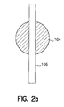
- FIGs 2a and 2b The coupling efficiency of this configuration is illustrated in Figures 2a and 2b.
- Figure 2a if a circular tube end 104 is imaged directly onto a slit 106, only 25% (for a 1 mm tube and 200 micron slit) of the aperture 104 is imaged onto the slit 106.
- the use of a fiber bundle 90 is illustrated in Figure 2b.
- Fiber cores 108 comprising the fiber bundle 90 occupy only a fraction of the usable area and scattered light that strikes other areas is not collected. The fraction of the area covered by the cores is typically approximately 65%, so almost 3 times more signal is collected with the circular-to-rectangular fiber bundle 90 than with direct imaging of a circular aperture onto a rectangular slit.
- a one piece circular-to-rectangular waveguide 92 is used in place of the fiber bundle 90. Similar to the fiber bundle 90, the one piece circular-to-rectangular waveguide 92 has a round aperture 94 on one end and a rectangular aperture 96 on the other end. The dimensions of the round aperture 94 are matched to the distal aperture of the hollow reflective tube 60 and the dimensions of the rectangular aperture 96 match the dimensions of the input slit of the spectrograph 100.
- One advantage of the one piece waveguide 92 is that all of the area is used for collection and transmission of light as opposed to the fiber bundle 90 where only 65% of the area is used.
- a disadvantage is that the numerical aperture for light exiting the rectangular aperture 96 may be affected by changing from a circular shape to the elongated rectangle (6mm x 0.2mm). Additionally, the one piece waveguide 92 may be less flexible than the fiber bundle 90.
- the circular-to-rectangular waveguide 92 There are several ways to produce the circular-to-rectangular waveguide 92.
- One way is to mold the circular-to-rectangular waveguide 92 out of glass or plastic into the exact shape desired. If a cladding layer is desired, the molded circular-to-rectangular waveguide 92 may be dipped in an appropriate material to produce the cladding layer.
- Another method of fabricating the circular-to-rectangular waveguide 92 is to take a glass or plastic circular waveguide, heat one end and press it into the desired rectangular shape.
- hollow tube 60 comprises a wall 62 surrounding a chamber 64.
- An interior surface 66 forms the boundary between the wall 62 and the chamber 64.
- Table 1 shows the fraction of power reaching the distal end of the tube for different reflection values of the wall 66 and different numbers of reflections. For example, for 37 reflections, the fraction of the input power reaching the distal end of the tube with a 90% reflective inner wall 66 is only 2% compared to 83% if the inner wall 66 is 99.9% reflective. TABLE 1 Losses as a Function of the Number of Reflections and Reflectivity Number of Reflections 90% Ref. 95% Ref. 98% Ref. 99% Ref. 99.9% Ref.
- the hollow reflective tube 60 with a highly reflective inner surface 66 may be produced in many configurations.
- it may comprise a glass tube with gold deposited on the inner surface.
- Gold is an excellent material because of it's high reflectivity above 650 nm and because it does not fluoresce or produce any Raman scattering. Silver also meets these criteria, but silver oxidizes over time (tarnishes) and this reduces the reflectivity. Silver can be overcoated with a protective dielectric layer to prevent oxidation, but this layer may produce Raman scattering and/or fluorescence and may reduce the reflectivity of the silver.
- Dielectric reflective coatings are less appropriate than the gold or silver because Raman scattering produced from the coating may overwhelm the desired Raman signal from the sample gas. Effective broadband dielectric reflective coatings are also difficult to produce for the grazing angles that occur in the tube. Coatings for the P-polarized light at grazing incidence are particularly problematical. Thus, metallic coatings are better suited for this system.
- One such reflective tube having a gold alloy structure that sheaths the inner surface of a hollow glass tube can be ordered from Hewlett Packard as "replacement light pipe" part number 05965-60155. This part is used in the Hewlett Packard 5965B Infrared Detector.
- Another reflective tube suitable for the present invention is a gold alloy tube available commercially from Epner Technology, Inc. in Brooklyn, New York.
- diode lasers In addition to the laser light characteristic of the diode laser, diode lasers also emit light over a wide region of the wavelength spectrum. Included in this broad band emission is light referred to as spontaneous emission. A portion of the spontaneous emission light may overlap the Raman wavelengths of interest and can overwhelm the desired Raman scattering. Furthermore, if lenses are used to collect and shape the diode laser output prior to entering the reflective hollow tube 60, fluorescence and Raman scattering may be generated in the lenses and this light can also overwhelm the desired Raman signal. Thus, it is advantageous to position band pass filter 70 between the laser 10 and the reflective hollow tube 60. Furthermore, it is advantageous to use a specially designed filter to reduce extraneous signals.
- the filter coating is sandwiched between two glass plates and sealed around the edges to prevent the coating material from absorbing moisture from the surrounding air which can destroy the filter.
- fluorescence and Raman scattering generated as the laser passes through the glass after it goes through the coating material can overwhelm the desired Raman scattering from the gas sample. This is true even if a low fluorescing glass, such as fused silica, is used. Therefore, the filter 70 should be made in such a way that the coating material will not absorb water from the surrounding atmosphere and be configured in a way which does not require the laser light to pass through any material except the filter material just prior to entering the hollow reflective tube 60. There are several methods to build this type of filter.
- the filter should be oriented so that the coated surface faces the entrance aperture of the hollow reflective tube 60, thereby preventing fluorescence and Raman scattering produced in the filter substrate from entering the hollow reflective tube 60.
- FIG. 4 illustrates a more detailed section view of the hollow reflective tube 60 of the present invention.
- the hollow reflective tube 60 includes a reflective inner layer 120 which forms the reflective inner surface 66 surrounded by a layer of sheath or substrate material 130.
- the chamber 64 in which the gas sample being analyzed is placed has an inlet port 140 and exit port 150 to allow the gas sample to be circulated through the chamber 64.
- the laser line pass filter 70 and the Raman band pass/laser line rejection filter 80 are shown as having filter coating layers 70c and 80c and substrate layers 70s and 80s, respectively. Filters 70 and 80 are also shown as forming the ends of the hollow tube 60 thereby closing the tube to form chamber 64 for containing the gas sample.
- a first alternative embodiment of the invention is shown in Figure 5.
- Light is produced by a diode laser 210.
- Beam shaping optics 220 collect the diode laser output 230, shape it appropriately, and direct the light 240 towards an aperture 250 in a proximate end of a hollow reflective tube 260.
- the light 230 Before entering the hollow reflective tube 260 the light 230 passes through one or more dielectric filters 270 that allow only a narrow wavelength band centered on the laser line to pass through the filters 270 and enter the hollow reflective tube 260 through the aperture 250.
- the filtered output from the diode laser 210 passes through the optical aperture 250 at the proximate end of the hollow reflective tube 260 into the hollow reflective tube 260.
- the aperture 250 and filter 270 are combined such that the filter 270 allows the laser light to enter the hollow reflective tube 260 and also serves to seal the aperture 250 of the hollow reflective tube 260 thus confining a sample gas within the hollow tube 260.
- the laser light then propagates through the hollow reflective tube 260 occasionally reflecting off the interior walls of the reflective hollow tube 260.
- some of the laser light is Raman scattered from the sample gas thereby generating Raman scattered light which has wavelengths that are characteristic of the constituents of the sample gas.
- One or more laser line rejection filters 280 are positioned near a distal end 282 of the reflective hollow tube 260.
- Laser line rejection filters 280 are similar in construction to the band pass filters 270, but they pass the wavelengths of Raman scattered light comprising the Raman spectrum and reject the laser wavelength. Thus, the Raman scattered light passes through the filters while the laser light is reflected back through the reflective hollow tube 260. This reflected laser light again generates Raman scattering as it travels through the sample in a direction back towards the laser 210, effectively doubling the single pass power of the system.
- the light exiting the reflective hollow tube 260 is collected by beam shaping optics 290 and delivered to an entrance slit 292 of a spectrograph 294 for detection.
- the reflective hollow tube 260 is substantially the same as the reflective hollow tube 60 previously described.
- FIGS 6a, 6b and 6c Second, third and fourth alternative embodiments of the invention are shown in Figures 6a, 6b and 6c.
- a laser beam enters a reflective hollow tube 360 through an aperture 350 and one or more dielectric filters 370 that allow only a narrow wavelength band centered on the laser line to pass through the filter(s) 370 and propagate through the hollow reflective tube 360.
- the aperture 350 and filter 370 are combined such that the filter 370 allows the laser light to enter the hollow reflective tube 360 and also serves to seal the aperture 350 of the hollow reflective tube 360 thus confining a sample gas within the hollow tube 360.
- the laser light then propagates through the hollow reflective tube 360 occasionally reflecting off the interior walls of the reflective hollow tube 360.
- laser line rejection filters 380 are positioned at a distal end of the reflective hollow tube 360.
- Laser line rejection filters 380 are similar in construction to the band pass filters 370, but they pass the wavelengths of Raman scattered light comprising the Raman spectrum and reject the laser wavelength.
- the Raman scattered light passes through the filters while the laser light is reflected back through the reflective hollow tube 360. This reflected laser light again generates Raman scattering as it travels through the sample in a direction back towards the laser entrance aperture 350, effectively doubling the single pass power of the system.
- the light exiting the reflective hollow tube 360 is delivered to an entrance slit of a spectrograph (not shown) by a fiber optic bundle 390 as previously described.
- the reflective hollow tube 360 is also substantially the same as the reflective hollow tube 60 previously described.
- a gradient index of refraction lens (GRIN lens) 392 is located adjacent the laser line rejection filter(s) 380 to improve the collection and delivery of the Raman scattered light from the gas sample to the optical fiber 390.
- the embodiment shown in Figure 6c also includes a second GRIN lens 394 located adjacent the laser line band pass filter(s) 370 to improve the collection, delivery and transmission of the laser beam from the diode laser (not shown) into the reflective hollow tube 360.
- a second GRIN lens 394 located adjacent the laser line band pass filter(s) 370 to improve the collection, delivery and transmission of the laser beam from the diode laser (not shown) into the reflective hollow tube 360.
- a fifth alternative embodiment of the invention is shown in Figure 7. Similar to the embodiment shown in Figure 1, light is produced by a diode laser 410.
- Beam shaping optics 420 collect the diode laser output 430, shape it appropriately, and direct the light 440 towards an aperture 450 in a proximate end of a hollow reflective tube 460.
- the light 440 Before entering the hollow reflective tube 460 the light 440 passes through a dielectric filter 470 that allows only a narrow wavelength band centered on the laser line to pass through the filter 470 and enter the hollow reflective tube 460 through the aperture 450.
- the filtered output from the diode laser 410 passes through the optical aperture 450 at the proximate end of the hollow reflective tube 460 into the hollow reflective tube 460.
- the aperture 450 and filter 470 are combined such that the filter 470 allows the laser light to enter the hollow reflective tube 460 and also serves to seal the aperture 450 of the hollow reflective tube 460 thus confining a sample gas within the hollow tube 460.
- the laser light then propagates through the hollow reflective tube 460 occasionally reflecting off the interior walls of the reflective hollow tube 460.
- a laser line rejection filter 480 is positioned at a distal end of the reflective hollow tube 460.
- Laser line rejection filter 480 is similar in construction to the band pass filter 470, but it passes the wavelengths of Raman scattered light comprising the Raman spectrum and rejects the laser wavelength. Thus, the Raman scattered light passes through the filter while the laser light is reflected back through the reflective hollow tube 460. This reflected laser light again generates Raman scattering as it travels through the sample in a direction back towards the laser 410, effectively doubling the single pass power of the system.
- the light exiting the reflective hollow tube 460 is collected by a fiber bundle 490.
- a proximate end of fiber bundle 490 is the same size as the reflective hollow tube exit aperture and can be polished so the filter coating 480 can be deposited directly onto the proximate end of the fiber bundle 490.
- the proximate end of fiber bundle 490 serves three functions: 1) it couples the light exiting from the hollow reflective tube 460 into the fiber 490; 2) it seals the distal end of the reflective hollow tube 460 thus confining the gas sample therein; and 3) it provides a substrate to support the filter 480.
- the fiber bundle 490 splits into multiple smaller fiber segments 492a, 492b, 492c, 492d, ..., wherein each of the segments 492a, 492b, 492c, 492d, ... is dedicated to directing a portion of the Raman scattered light from the gas sample in the reflective hollow tube 460 to a discrete detector channel 500a, 500b, 500c, 500d,...
- detector channel 500d comprises a collection/collimation lens 504 which is f/# matched to the fiber 492d to optimally collect and collimate light exiting a distal end 508d of fiber segment 492d.
- a Raman line pass filter 508 receives the light from the lens 504 and passes only the Raman lines which that particular channel is designed to detect. Thus, each channel may be configured to detect a specific Raman line(s). After passing through the filter 508, the desired Raman line(s) are focused by a focusing lens 512 on a detector 516.
- the detector 516 may be any suitable light detector including but not limited to a photodiode or photomultiplier tube. Further details of multiple channel Raman detectors for gas analysis are described in U.S. Patent No. 4,784,486 entitled “Multi-Channel Molecular Gas Analysis By Laser-Activated Raman Light Scattering", the entire contents of which are hereby incorporated herein by reference.
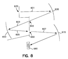
- the laser line rejection filters 80, 280, 380 and 480 may be replaced with two (2) gratings used in a subtractive dispersion mode as shown in Figure 8.
- Light (601) exiting the reflective tube (not shown) passes through an entrance slit 620 and is incident on a first diffraction grating 630.
- Grating 620 produces a spectrally dispersed image of the entrance slit 620 at a first intermediate slit 640.
- Slit 640 is relatively wide, allowing the wavelengths of interest to pass through while blocking the laser line.
- This filtered light 603 continues on and is incident on another grating 650.
- Grating 650 acts as the reciprocal of the first grating 630, recombining the dispersed light and refocusing the filtered light 605 onto a second intermediate slit 660.
- Slit 660 is much narrower than the first intermediate slit 640.
- the filtered light 607 is then incident on a third grating 670 which acts to produce a spectrally dispersed image of the second intermediate slit 660 on a CCD 680.
- the first two gratings 630 and 650 act as a filter to remove the laser light
- the third grating 670 works in the conventional manner to disperse the wavelengths of the light contained in the beam 607 for detection by the CCD 680.
- Each of the previous embodiments which employ a spectrograph detector includes some type of dispersion element, for example, a grating, prism, etc.
- the subtractive dispersion system shown in Figure 8 is advantageous in that the laser light never passes through any filters or glass, thus fluorescence or Raman scattering from the filter coating or the glass is eliminated.
Abstract
Description
- The invention relates generally to gas analysis using Raman scattering and more specifically, to a gas analysis system having a laser diode pumped reflective hollow tube gas analysis cell. The present invention may be used in conjunction with conventional discrete or spectrometric detectors to perform molecular gas analysis in a variety of applications.
- Raman light scattering has been successfully used in critical care situations to continuously monitor a patient's respiratory gases. This technique is based on the effect which occurs when monochromatic light interacts with vibrational/rotational modes of gas molecules to produce scattered light which is frequency shifted from that of the incident radiation by an amount corresponding to the vibrational/rotational energies of the scattering gas molecules. If the incident light photon loses energy in the collision, it is re-emitted as scattered light with lower energy and consequently lower frequency than the incident photon. In a similar manner, if the incident photon gains energy in the collision, it is re-emitted as scattered light with higher energy and higher frequency than the incident photon. Since these energy shifts are species-specific, analysis of the various frequency components present in the Raman scattering spectrum of a sample provides chemical identification of the gases present in the scattering volume. The intensity of the various frequency components or Raman spectral lines provides quantification of the gases present, providing suitable calibrations have been made. In this manner, Raman light scattering can be employed to determine the identity and quantity of various respiratory and anesthetic gases present in a patient's breath in operating room and intensive care situations.
- In addition to critical care situations, Raman light scattering gas analysis can also be used in many industrial applications such as stack gas analysis for combustion control, process control, fermentation monitoring, and pipeline gas mixture control. This analysis technique can also be extended to meet environmental monitoring needs in many areas such as escaped anesthetic agents in the operating room, air pollution, auto emissions testing and submarine atmosphere monitoring.
- Systems developed for analysis of gases in critical care situations utilizing Raman scattering typically employ gas cells which contain a sample of the patient's respiratory gas to be analyzed. The gas sampling cell is located either within the resonant cavity of a laser or outside the cavity. In an intracavity system, a laser beam is directed through the resonant cavity such that it intercepts the gas within the sampling cell. Raman scattered light from the gas analysis region within the cell is collected and analyzed by conventional discrete or spectrometric detectors to perform molecular gas analysis.
- At the center of these systems is the Raman scattering phenomenon which produces scattered radiation of a very weak intensity. There has been a long felt need to improve the efficiency, i.e., the signal to noise ratio, and lower the cost of Raman scattering based instruments, but progress has been hindered by the weak intensity of the scattered radiation and the numerous sources of noise.
- One source of extraneous background is the laser. This background is detrimental in that it adds noise to the signal. In a gas laser, the laser produces not only the desired laser light at a specific wavelength, but also a broad spectrum of light sometimes called plasma glow. Similarly, a diode laser emits light over a wide region of the wavelength spectrum, sometimes called spontaneous emission, in addition to the wavelength specific laser line(s). Some of the extraneous light from either type of laser, plasma glow or spontaneous emission, often overlaps the wavelengths of Raman scattered light of interest and can even overwhelm the Raman scattering.
- Another source of system background is often due to the optical elements in the system. For example, if lenses or other optical elements are used to collect and shape light emitted by the laser, the interaction of the laser light with the lenses and elements may produce output fluorescence and Raman scattering characteristic of the materials in the lenses and elements. This output fluorescence and Raman scattering from the lenses and other optical elements can overwhelm out the Raman signals produced by the gas sample being analyzed. Optical filters, often used in Raman scattering systems, are also potential sources of extraneous fluorescence and Raman scattering. Typically, a filter comprises a filter coating which is deposited on a supporting substrate, for example glass. In order to prevent the filter coating from absorbing moisture from the air, it may be sandwiched between two glass plates and sealed around the edges. However, if such a filter is used in a Raman gas analysis system where the laser light interacts with the filter, the fluorescence and Raman scattering generated as the laser passes through the glass can produce extraneous light which can overwhelm the Raman scattering from the gas sample. This occurs even if a low fluorescing glass such as fused silica is used.
- The device disclosed in European Patent Application publication number 0 557 655 A1 entitled "System for Collecting Weakly Scattered Optical Signals" describes a system for enhancing the collection efficiency of a gas analysis system. This document discloses a system having a laser which illuminates an unknown gas contained by a long hollow chamber having a highly reflective coating. A laser beam propagates along the longitudinal dimension of the interior region of the long hollow chamber without contacting the reflective coating. The reflective coating, either on the inner or outer surface of a transparent hollow tube, is designed to reflect radiation which is scattered from the laser beam by the unknown gas contained within the long hollow chamber, thus enhancing the collection efficiency for light produced by the interaction of the laser beam with the gas sample, e.g. Raman scattered light. The laser beam is specifically prevented from interacting with the reflective coating since such interactions produce not only a reflected laser beam, but a weak collateral radiation, e.g. fluorescence and Raman scattering as discussed previously. This weak collateral radiation is unwanted because it tends to interfere with the measurement of the radiation scattered by the unknown gas. Thus, the approach taken by this reference for reducing the effect of the weak collateral radiation produced by the laser and by the interaction of the laser with reflective coatings and filters is to minimize such interactions by directing the laser beam along the longitudinal axis such that the laser beam does not interact with the reflective coating. Additionally, interactions with filters are eliminated by not having any filters in the laser beam path. While this approach may succeed in reducing collateral radiation due to interactions of the laser beam with the walls and/or reflective coating of the long hollow chamber, it also limits the kind of lasers which can be used. This is due to the tight collimation required to keep the incident laser light away from the walls and/or reflective coating of the long hollow chamber. It is difficult to produce a narrow, collimated beam with high powered diode lasers, thus reducing the intensity of light on the gas sample.
- U.S. Patent No. 3,556,659 entitled "LASER-EXCITED RAMAN SPECTROMETER" discloses a laser-excited Raman spectrometer in which a laser output beam having a very small diameter is projected along the length of a capillary sample cell, rather than being projected in a transverse direction. The beam is substantially coaxial with the cell and the resultant Raman scattered light travelling in the general direction of the cell axis is detected. This reference also emphasizes the importance of confining the laser beam to the capillary bore, with very little of it traversing the capillary wall. This is done to minimize the scattering of the laser radiation from the cell wall and excitation of fluorescence in the cell wall. It is also noted that aligning the laser beam with the capillary bore requires accurate alignment but is worth the effort because it minimizes fluorescence of the glass wall and scattering of light from the wall itself.
- The device disclosed in European Patent Application publication number 0 557 658 A1 entitled "RAMAN SPECTROSCOPY OF RESPIRATORY GASES" describes a system for determining the composition and concentration of gases present in a patient's airway by measurement of the spectrum of Raman scattered light from these gases. The gases present are assumed to be drawn from a predetermined set of gases with known Raman scattering spectra, and the concentrations are determined by solution of a matrix equation Ac = b, where the c vector components are the unknown concentrations and the b vector components are determined from measurements of the Raman scattering intensities in a plurality of wavelength or wavenumber intervals. The gas sample flows through an optical waveguide similar to that disclosed in previously discussed European Patent Application publication number 0 557 655 A1. Collection optics including mirrors and filters direct the Raman scattered light from the sample into a diffraction grating spectrometer. The composition of the gas mixture is determined by analyzing the measured spectrum, which represents the sum of the spectra of the individual gases, weighted by the concentration of each gaseous component. Since this system utilizes components which are the same or similar to those disclosed in European Patent Application publication number 0 557 655 A1, i.e., the optical waveguide wherein the gas sample interacts with the laser, it also exhibits similar shortcomings. Additionally, as with any optical system, the collection and transportation of light from the optical waveguide to the spectrometer with mirrors and/or lenses is inherently inefficient.
- What is needed is a gas monitoring system that: 1 ) reduces the level of non-laser light which is detected along with the desired Raman scattered light from the gas sample; 2) reduces extraneous fluorescence and Raman scattering produced by the interaction of the laser light with system components; and 3) efficiently couples the desired Raman scattered light from the gas sample to a detector or spectrometer.
- It is an aim of the present invention to provide a gas monitoring system having a hollow reflective tube that: 1) reduces the level of non-laser light which is detected along with the desired Raman scattered light from the gas sample; 2) reduces extraneous fluorescence and Raman scattering produced by the interaction of the laser light with system components; and 3) efficiently couples the desired Raman scattered light from the gas sample to a detector or spectrometer.
- According to one aspect of the present invention; an apparatus for the analysis of gases in a gas sample by Raman light scattering comprises:
- a laser light source for producing and transmitting a laser beam of optical radiation along a longitudinal axis;
- a gas sample cell to receive and hold the gas sample along said longitudinal axis in an interior region of said gas cell, wherein said gas sample cell is positioned to receive said laser beam of optical radiation from said laser light source via a first end of said gas sample cell, said gas sample cell further having a second end and a highly reflective interior surface suitable for reflecting said laser beam and Raman scattered light from the gas sample;
- a laser line pass filter which transmits a narrow wavelength band of light centered on a laser line characteristic of said laser light source, wherein said laser line pass filter is positioned at said first end of said gas sample cell thereby transmitting that portion of said laser beam containing said characteristic laser line into said gas sample cell and rejecting substantially all other wavelengths comprising said laser beam;
- a laser line rejection filter which transmits substantially all wavelengths except the narrow wavelength band of light centered on the laser line characteristic of said laser light source, wherein said laser line rejection filter is positioned at said second end of said gas sample cell thereby transmitting light scattered by the gas sample at wavelengths different from the wavelength of the laser line characteristic of said laser light source out of said gas sample cell and reflecting said laser beam back through said sample cell; and
- a detector optically connected to said second end of said gas cell for receiving and detecting said light scattered from said gas sample and transmitted through said laser line rejection filter.
- According to a further aspect of the present invention, a method of analyzing a gas sample comprises:
- providing a laser which produces a laser beam which propagates substantially along a longitudinal axis;
- providing a laser line pass filter in the path of said laser beam which transmits a specific wavelength characteristic of said laser;
- directing said filtered laser beam through a first end of a hollow tube having a longitudinal axis which is substantially aligned with said laser beam longitudinal axis wherein said hollow tube confines said gas sample inside a region surrounded by a highly reflective surface so that said filtered laser beam propagates through said sample such that a portion of said filtered laser beam reflects from said highly reflective surface of said hollow tube while propagating through said sample;
- providing a laser line rejection filter at a second end of said hollow tube which transmits a wavelength band including Raman lines characteristic of the constituents of said gas sample and reflects said specific wavelength characteristic of said laser; and
- detecting and analyzing said Raman lines which are characteristic of the constituents of said gas sample to identify said constituents.
- In a first embodiment, the present invention is an apparatus for the analysis of gases in a gas sample by Raman light scattering comprising: a laser light source for producing and transmitting a laser beam of optical radiation along a longitudinal axis; a gas sample cell to receive and hold the gas sample along the longitudinal axis in an interior region of the gas cell, wherein the gas sample cell is positioned to receive the laser beam of optical radiation from the laser light source via a first end of the gas sample cell, the gas sample cell further having a second end and a highly reflective interior surface suitable for reflecting the laser beam and Raman scattered light from the gas sample; a laser line pass filter which transmits a narrow wavelength band of light centered on a laser line characteristic of the laser light source, wherein the laser line pass filter is positioned at the first end of the gas sample cell thereby transmitting that portion of the laser beam containing the characteristic laser line into the gas sample cell and rejecting substantially all other wavelengths comprising the laser beam; a laser line rejection filter which transmits substantially all wavelengths except the narrow wavelength band of light centered on the laser line characteristic of the laser light source, wherein the laser line rejection filter is positioned at the second end of the gas sample cell thereby transmitting light scattered by the gas sample at wavelengths different from the wavelength of the laser line characteristic of the laser light source out of the gas sample cell and reflecting the laser beam back through the sample cell; and a detector optically connected to the second end of the gas cell for receiving and detecting the light scattered from the gas sample and transmitted through the laser line rejection filter. The laser light source may further comprise a diode laser. In some embodiments, the gas sample cell may be an elongate hollow tube having a substantially uniform interior diameter and a length which is substantially greater than the interior diameter. Additionally, the highly reflective interior surface of the gas sample cell may comprise a metallic material. More specifically, the highly reflective interior surface of the gas sample cell may be gold. Additionally, the laser line pass filter may comprise a filter coating formed on a substrate. The laser line pass filter is positioned immediately adjacent to the first end of the gas sample cell thereby closing the first end of the gas sample cell. Furthermore, the laser line pass filter is positioned adjacent the first end of the gas sample cell such that the filter coating faces the interior region of the gas sample cell. Additionally, a preferred embodiment comprises a filter coating which is substantially non-hydrophilic. One such non-hydrophilic filter coating comprises tantalum. Another such non-hydrophilic filter coating comprises silicon dioxide. In yet another embodiment, the laser line rejection filter comprises a filter coating formed on a substrate. The laser line rejection filter is positioned immediately adjacent to the second end of the gas sample cell thereby closing the second end of the gas sample cell. Furthermore, the laser line rejection filter is positioned adjacent the second end of the gas sample cell such that the filter coating faces the interior region of the gas sample cell. In some embodiments, the detector comprises a spectrograph. Some embodiments further comprise a lens system positioned intermediate the laser light source and the gas sample cell, the lens collecting and focusing the laser beam of optical radiation from the laser light source and directing the laser beam of optical radiation into the first end of the gas sample cell. This lens may further comprise a gradient index of refraction (GRIN) lens. Additionally, some embodiments further comprise an optical fiber positioned intermediate the gas sample cell and the detector, the optical fiber transmitting the light scattered by the gas sample at wavelengths different from the wavelength of the laser line characteristic of the laser light source out of the gas sample cell into the detector. Some embodiments further comprise a light guide positioned intermediate the gas sample cell and the detector, the optical fiber transmitting the light scattered by the gas sample at wavelengths different from the wavelength of the laser line characteristic of the laser light source out of the gas sample cell into the detector. In some embodiments, the gas sample cell further comprises a gas input port and a gas output port. In yet another embodiment, the invention further comprises an optical fiber positioned intermediate the gas sample cell and the detector, the optical fiber having an input and a plurality of outputs, wherein each output transmits a portion of the light scattered by the gas sample at wavelqngths different from the wavelength of the laser line characteristic of the laser light source out of the gas sample cell into a detector channel.
- In a second embodiment, the present invention is an apparatus for the analysis of gases in a gas sample by Raman light scattering comprising: a hollow tube for holding a sample of a gas to be analyzed, the hollow tube having a highly reflective interior tubular wall enclosing a bore forming a sample region, the bore having a length that is at least five times greater than its diameter, the bore having a longitudinal axis along its length; a laser light source for producing and transmitting a laser beam of optical radiation into the hollow tube bore through a first end of the hollow tube such that a first portion of the beam of optical radiation propagates through the bore along the bore longitudinal axis and a second portion of the beam of optical radiation propagates through the bore by reflecting from the highly reflective interior tubular wall; a laser line pass filter which transmits a narrow wavelength band of light centered on a laser line characteristic of the laser light source, wherein the laser line pass filter is positioned at the first end of the hollow tube thereby transmitting that portion of the laser beam containing the characteristic laser line into the bore and rejecting substantially all other wavelengths comprising the laser beam; a laser line rejection filter which transmits substantially all wavelengths except the narrow wavelength band of light centered on the laser line characteristic of the laser light source, wherein the laser line rejection filter is positioned at a second end of the hollow tube thereby transmitting light scattered by the gas sample at wavelengths different from the wavelength of the laser line characteristic of the laser light source out of the hollow tube bore and reflecting the laser beam back through the hollow tube bore; and a detector optically connected to the second end of the hollow tube for receiving and detecting the light scattered from the gas sample and transmitted through the laser line rejection filter. In another aspect of this embodiment the laser light source comprises a diode laser. Additionally, the highly reflective interior tubular wall of the hollow tube may comprise a metallic material, for example gold. In another aspect of the second embodiment, the laser line pass filter comprises a filter coating formed on a substrate, wherein the laser line pass filter is positioned immediately adjacent to the first end of the hollow tube thereby closing the first end of the hollow tube. The laser line pass filter is positioned adjacent the first end of the hollow tube such that the filter coating faces the sample region of the hollow tube. In other aspects of the second embodiment the filter coating is substantially non-hydrophilic and may comprise, for example tantalum and/or silicon dioxide. In yet another aspect of the second embodiment, the laser line rejection filter comprises a filter coating formed on a substrate, the laser line rejection filter positioned immediately adjacent to the second end of the hollow tube thereby closing the second end of the hollow tube, the laser line rejection filter positioned adjacent the second end of the hollow tube such that the filter coating faces the sample region of the hollow tube. In another aspect of the second embodiment, the detector comprises a spectrograph. Yet another aspect of the second embodiment further comprises a lens positioned intermediate the laser light source and the hollow tube, the lens collecting and focusing the laser beam of optical radiation from the laser light source and directing the laser beam of optical radiation into the first end of the hollow tube. This lens may further comprise a gradient index of refraction (GRIN) lens. Other versions of the second embodiment include an optical fiber positioned intermediate the hollow tube and the detector, the optical fiber transmitting the light scattered by the gas sample at wavelengths different from the wavelength of the laser line characteristic of the laser light source out of the hollow tube into the detector. Another aspect of the present invention, further comprises a light guide positioned intermediate the hollow tube and the detector, the optical fiber transmitting the light scattered by the gas sample at wavelengths different from the wavelength of the laser line characteristic of the laser light source out of the hollow tube into the detector. In another aspect of the second embodiment, the hollow tube further comprises a gas input port and a gas output port. Yet another aspect of the second embodiment further comprises an optical fiber positioned intermediate the hollow tube and the detector, the optical fiber having an input and a plurality of outputs, wherein each output transmits a portion of the light scattered by the gas sample at wavelengths different from the wavelength of the laser line characteristic of the laser light source out of the hollow tube into a separate detector channel.
- Embodiments of the invention will now be described, by way of example, reference being made to the Figures of the accompanying diagrammatic drawings in which:-
- Figure 1 is a schematic diagram illustrating a preferred embodiment of the present invention having a fiber optic coupling to a conventional spectrograph;
- Figures 2a and 2b are schematic diagrams illustrating the efficiency of the fiber optic coupling of the present invention;
- Figure 2c is a schematic diagram illustrating a one piece circular-to-rectangular waveguide;
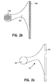
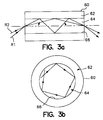
- Figures 3a and 3b are schematic diagrams illustrating the paths of laser beam light rays through the reflective hollow tube of the present invention;
- Figure 4 is a cross section of the reflective hollow tube/gas cell of the present invention illustrating details thereof;
- Figure 5 is a schematic diagram illustrating a first alternative embodiment of the present invention having a conventional bulk optics coupling to a conventional spectrograph;
- Figures 6a, 6b and 6c are schematic diagrams illustrating second, third and fourth alternative embodiments of the present invention;
- Figure 7 is a schematic diagram illustrating a fifth alternative embodiment of the present invention having a multi-channel detector system; and
- Figure 8 is a schematic diagram illustrating two gratings used in a subtractive dispersion mode to replace a laser line rejection filter.
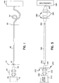
- In the embodiment of the invention illustrated in Figure 1, light is produced by a
diode laser 10.Beam shaping optics 20 collect thediode laser output 30, shape it appropriately, and direct the light 40 towards anaperture 50 in a proximate end of a hollowreflective tube 60. Before entering the hollowreflective tube 60 the light 40 passes through adielectric filter 70 that allows only a narrow wavelength band centered on the laser line to pass through thefilter 70 and enter the hollowreflective tube 60 through theaperture 50. Thus, the filtered output from thediode laser 10 passes through theoptical aperture 50 at the proximate end of the hollowreflective tube 60 into the hollowreflective tube 60. In some embodiments, theaperture 50 andfilter 70 are combined such that thefilter 70 allows the laser light to enter the hollowreflective tube 60 and also serves to seal theaperture 50 of the hollowreflective tube 60 thus confining a sample gas within thehollow tube 60. The laser light then propagates through the hollowreflective tube 60 occasionally reflecting off the interior walls of the reflectivehollow tube 60. As the laser light propagates through the gas sample contained within the reflectivehollow tube 60, some of the laser light is Raman scattered from the sample gas thereby generating Raman scattered light which has wavelengths that are characteristic of the constituents of the sample gas. A laserline rejection filter 80 is positioned at a distal end of the reflectivehollow tube 60. Laserline rejection filter 80 is similar in construction to theband pass filter 70, but it passes the wavelengths of Raman scattered light comprising the Raman spectrum and rejects the laser wavelength. Thus, the Raman scattered light passes through thefilter 80 while the laser light is reflected back through the reflectivehollow tube 60. This reflected laser light again generates Raman scattering as it travels through the sample in a direction back towards thelaser 10, effectively doubling the single pass power of the system. In the embodiment illustrated in Figure 1, the light exiting the reflectivehollow tube 60 is collected by afiber bundle 90. A proximate end offiber bundle 90 is the same size as the reflective hollow tube exit aperture and can be polished so thefilter coating 80 can be deposited directly onto the proximate end of thefiber bundle 90. Thus, the proximate end offiber bundle 90 serves three functions: 1) it couples the light exiting from the hollowreflective tube 60 into thefiber 90; 2) it seals the distal end of the reflectivehollow tube 60 thus confining the gas sample therein; and 3) it provides a substrate to support thefilter 80. Thefiber bundle 90 has a distal end which is connected to aspectrograph 100. Preferably, the numerical aperture (N.A.) of thefiber bundle 90 is chosen to match the input numerical aperture of thespectrograph 100. For example, if the numerical aperture of thespectrograph 100 is 0.29, then thefiber bundle 90 is selected to have a numerical aperture of 0.29. - Collecting the light from the reflective
hollow tube 60 and transporting it to thespectrograph 100 with thefiber bundle 90 is advantageous since the proximate end of thefiber bundle 90 can be circular to match the distal aperture of thehollow tube 60 and the distal end of thefiber bundle 90 can be a rectangular linear array to match the shape of the input slit of thespectrograph 100. In many applications, the linear array can serve as the entrance aperture, or the slit, of the spectrograph. Thus, thefiber bundle 90 may provide a simple and efficient means for transforming from the circular geometry of thehollow tube 60 to the narrow slit needed for the spectrograph. In one embodiment of the present invention, thefiber bundle 90 comprises 200 micron cores with a 20 micron cladding. The coupling efficiency of this configuration is illustrated in Figures 2a and 2b. As shown in Figure 2a, if acircular tube end 104 is imaged directly onto aslit 106, only 25% (for a 1 mm tube and 200 micron slit) of theaperture 104 is imaged onto theslit 106. The use of afiber bundle 90 is illustrated in Figure 2b.Fiber cores 108 comprising thefiber bundle 90 occupy only a fraction of the usable area and scattered light that strikes other areas is not collected. The fraction of the area covered by the cores is typically approximately 65%, so almost 3 times more signal is collected with the circular-to-rectangular fiber bundle 90 than with direct imaging of a circular aperture onto a rectangular slit. - In another embodiment, shown in Figure 2c, a one piece circular-to-
rectangular waveguide 92 is used in place of thefiber bundle 90. Similar to thefiber bundle 90, the one piece circular-to-rectangular waveguide 92 has around aperture 94 on one end and arectangular aperture 96 on the other end. The dimensions of theround aperture 94 are matched to the distal aperture of the hollowreflective tube 60 and the dimensions of therectangular aperture 96 match the dimensions of the input slit of thespectrograph 100. One advantage of the onepiece waveguide 92 is that all of the area is used for collection and transmission of light as opposed to thefiber bundle 90 where only 65% of the area is used. A disadvantage is that the numerical aperture for light exiting therectangular aperture 96 may be affected by changing from a circular shape to the elongated rectangle (6mm x 0.2mm). Additionally, the onepiece waveguide 92 may be less flexible than thefiber bundle 90. - There are several ways to produce the circular-to-
rectangular waveguide 92. One way is to mold the circular-to-rectangular waveguide 92 out of glass or plastic into the exact shape desired. If a cladding layer is desired, the molded circular-to-rectangular waveguide 92 may be dipped in an appropriate material to produce the cladding layer. Another method of fabricating the circular-to-rectangular waveguide 92 is to take a glass or plastic circular waveguide, heat one end and press it into the desired rectangular shape. - The importance of using a highly reflective
hollow tube 60 to enhance the Raman scattered light signal is illustrated in Figures 3a and 3b and the data in Table 1. As shown in Figure 3a,hollow tube 60 comprises awall 62 surrounding achamber 64. Aninterior surface 66 forms the boundary between thewall 62 and thechamber 64. The paths of two light rays, R1 and R2, propagating through thechamber 64 at different angles by reflecting off of thewall 62 are shown in Figure 3a. If the light is focused into thetube 60 at f/# = f/2, the tube is 1 mm in diameter, and 6" long, the light is reflected at least 38 times for the steepest rays. In fact it will be many more reflections because the rays are spiraling down the tube as shown in Figure 3b. Table 1 shows the fraction of power reaching the distal end of the tube for different reflection values of thewall 66 and different numbers of reflections. For example, for 37 reflections, the fraction of the input power reaching the distal end of the tube with a 90% reflectiveinner wall 66 is only 2% compared to 83% if theinner wall 66 is 99.9% reflective.TABLE 1 Losses as a Function of the Number of Reflections and Reflectivity Number of Reflections 90% Ref. 95% Ref. 98% Ref. 99% Ref. 99.9% Ref. 1 90% 95% 98% 99% 100% 3 73% 86% 94% 97% 99% 5 59% 77% 90% 95% 98% 7 48% 70% 87% 93% 97% 9 39% 63% 83% 91% 96% 11 31% 57% 80% 90% 95% 13 25% 51% 77% 88% 94% 15 21% 46% 74% 86% 93% 17 17% 42% 71% 84% 92% 19 14% 38% 68% 83% 91% 21 11% 34% 65% 81% 90% 23 9% 31% 63% 79% 89% 25 7% 28% 60% 78% 88% 27 6% 25% 58% 76% 87% 29 5% 23% 56% 75% 86% 31 4% 20% 53% 75% 86% 33 3% 18% 51% 72% 85% 35 3% 17% 49% 70% 84% 37 2% 15% 47% 69% 83% 39 2% 14% 45% 68% 82% 41 1% 12% 44% 66% 81% 43 1% 11% 42% 65% 81% 45 1% 10% 40% 64% 80% 47 1% 9% 39% 62% 79% 49 1% 8% 37% 61% 78% 51 0% 7% 36% 60% 77% - Another result of the laser light spiraling through the
chamber 64 of thetube 60 is that the polarization becomes scrambled. The resulting Raman scattered light is emitted in all directions but only those rays that don't go through too many reflections will exit the tube and be collected. - The hollow
reflective tube 60 with a highly reflectiveinner surface 66 may be produced in many configurations. For example, it may comprise a glass tube with gold deposited on the inner surface. Gold is an excellent material because of it's high reflectivity above 650 nm and because it does not fluoresce or produce any Raman scattering. Silver also meets these criteria, but silver oxidizes over time (tarnishes) and this reduces the reflectivity. Silver can be overcoated with a protective dielectric layer to prevent oxidation, but this layer may produce Raman scattering and/or fluorescence and may reduce the reflectivity of the silver. Dielectric reflective coatings are less appropriate than the gold or silver because Raman scattering produced from the coating may overwhelm the desired Raman signal from the sample gas. Effective broadband dielectric reflective coatings are also difficult to produce for the grazing angles that occur in the tube. Coatings for the P-polarized light at grazing incidence are particularly problematical. Thus, metallic coatings are better suited for this system. - One such reflective tube having a gold alloy structure that sheaths the inner surface of a hollow glass tube can be ordered from Hewlett Packard as "replacement light pipe" part number 05965-60155. This part is used in the Hewlett Packard 5965B Infrared Detector.
- Another reflective tube suitable for the present invention is a gold alloy tube available commercially from Epner Technology, Inc. in Brooklyn, New York.
- Some prior art systems use a reflective coating on the outer surface of a glass tube. This is not optimum for the present system since the light must pass through the glass before being reflected. Undesired Raman scattering and fluorescence will be generated in the glass as the laser light travels through the glass before and after being reflected.
- In addition to the laser light characteristic of the diode laser, diode lasers also emit light over a wide region of the wavelength spectrum. Included in this broad band emission is light referred to as spontaneous emission. A portion of the spontaneous emission light may overlap the Raman wavelengths of interest and can overwhelm the desired Raman scattering. Furthermore, if lenses are used to collect and shape the diode laser output prior to entering the reflective
hollow tube 60, fluorescence and Raman scattering may be generated in the lenses and this light can also overwhelm the desired Raman signal. Thus, it is advantageous to positionband pass filter 70 between thelaser 10 and the reflectivehollow tube 60. Furthermore, it is advantageous to use a specially designed filter to reduce extraneous signals. Typically, the filter coating is sandwiched between two glass plates and sealed around the edges to prevent the coating material from absorbing moisture from the surrounding air which can destroy the filter. However, if such a filter is used in a Raman gas analysis system, fluorescence and Raman scattering generated as the laser passes through the glass after it goes through the coating material can overwhelm the desired Raman scattering from the gas sample. This is true even if a low fluorescing glass, such as fused silica, is used. Therefore, thefilter 70 should be made in such a way that the coating material will not absorb water from the surrounding atmosphere and be configured in a way which does not require the laser light to pass through any material except the filter material just prior to entering the hollowreflective tube 60. There are several methods to build this type of filter. One way is to use different coating materials that produce harder coatings that do not absorb water. Materials such as tantalum and SiO₂ produce such coatings. Another method is to use a different coating process, such as ion beam sputtering, that produces coatings that do not absorb water. Other methods and materials will be obvious to one skilled in the art of coatings. Finally, the filter should be oriented so that the coated surface faces the entrance aperture of the hollowreflective tube 60, thereby preventing fluorescence and Raman scattering produced in the filter substrate from entering the hollowreflective tube 60. - Figure 4 illustrates a more detailed section view of the hollow
reflective tube 60 of the present invention. The hollowreflective tube 60 includes a reflectiveinner layer 120 which forms the reflectiveinner surface 66 surrounded by a layer of sheath orsubstrate material 130. Thechamber 64 in which the gas sample being analyzed is placed has aninlet port 140 andexit port 150 to allow the gas sample to be circulated through thechamber 64. Additionally, the laserline pass filter 70 and the Raman band pass/laserline rejection filter 80 are shown as having filter coating layers 70c and 80c andsubstrate layers Filters hollow tube 60 thereby closing the tube to formchamber 64 for containing the gas sample. - A first alternative embodiment of the invention is shown in Figure 5. Light is produced by a
diode laser 210.Beam shaping optics 220 collect thediode laser output 230, shape it appropriately, and direct the light 240 towards anaperture 250 in a proximate end of a hollowreflective tube 260. Before entering the hollowreflective tube 260 the light 230 passes through one or moredielectric filters 270 that allow only a narrow wavelength band centered on the laser line to pass through thefilters 270 and enter the hollowreflective tube 260 through theaperture 250. Thus, the filtered output from thediode laser 210 passes through theoptical aperture 250 at the proximate end of the hollowreflective tube 260 into the hollowreflective tube 260. In some embodiments, theaperture 250 and filter 270 are combined such that thefilter 270 allows the laser light to enter the hollowreflective tube 260 and also serves to seal theaperture 250 of the hollowreflective tube 260 thus confining a sample gas within thehollow tube 260. The laser light then propagates through the hollowreflective tube 260 occasionally reflecting off the interior walls of the reflectivehollow tube 260. As the laser light propagates through the gas sample contained within the reflectivehollow tube 260, some of the laser light is Raman scattered from the sample gas thereby generating Raman scattered light which has wavelengths that are characteristic of the constituents of the sample gas. One or more laser line rejection filters 280 are positioned near adistal end 282 of the reflectivehollow tube 260. Laser line rejection filters 280 are similar in construction to the band pass filters 270, but they pass the wavelengths of Raman scattered light comprising the Raman spectrum and reject the laser wavelength. Thus, the Raman scattered light passes through the filters while the laser light is reflected back through the reflectivehollow tube 260. This reflected laser light again generates Raman scattering as it travels through the sample in a direction back towards thelaser 210, effectively doubling the single pass power of the system. In the embodiment illustrated in Figure 5, the light exiting the reflectivehollow tube 260 is collected bybeam shaping optics 290 and delivered to an entrance slit 292 of aspectrograph 294 for detection. The reflectivehollow tube 260 is substantially the same as the reflectivehollow tube 60 previously described. - Second, third and fourth alternative embodiments of the invention are shown in Figures 6a, 6b and 6c. As shown in Figures 6a, 6b and 6c a laser beam enters a reflective
hollow tube 360 through anaperture 350 and one or moredielectric filters 370 that allow only a narrow wavelength band centered on the laser line to pass through the filter(s) 370 and propagate through the hollowreflective tube 360. In these embodiments, theaperture 350 and filter 370 are combined such that thefilter 370 allows the laser light to enter the hollowreflective tube 360 and also serves to seal theaperture 350 of the hollowreflective tube 360 thus confining a sample gas within thehollow tube 360. The laser light then propagates through the hollowreflective tube 360 occasionally reflecting off the interior walls of the reflectivehollow tube 360. As the laser light propagates through the gas sample contained within the reflectivehollow tube 360, some of the laser light is Raman scattered from the sample gas thereby generating Raman scattered light which has wavelengths that are characteristic of the constituents of the sample gas. One or more laser line rejection filters 380 are positioned at a distal end of the reflectivehollow tube 360. Laser line rejection filters 380 are similar in construction to the band pass filters 370, but they pass the wavelengths of Raman scattered light comprising the Raman spectrum and reject the laser wavelength. Thus, the Raman scattered light passes through the filters while the laser light is reflected back through the reflectivehollow tube 360. This reflected laser light again generates Raman scattering as it travels through the sample in a direction back towards thelaser entrance aperture 350, effectively doubling the single pass power of the system. - In the embodiment illustrated in Figure 6a, the light exiting the reflective
hollow tube 360 is delivered to an entrance slit of a spectrograph (not shown) by afiber optic bundle 390 as previously described. The reflectivehollow tube 360 is also substantially the same as the reflectivehollow tube 60 previously described. In the embodiments shown in Figures 6b and 6c, a gradient index of refraction lens (GRIN lens) 392 is located adjacent the laser line rejection filter(s) 380 to improve the collection and delivery of the Raman scattered light from the gas sample to theoptical fiber 390. Similarly, the embodiment shown in Figure 6c, also includes asecond GRIN lens 394 located adjacent the laser line band pass filter(s) 370 to improve the collection, delivery and transmission of the laser beam from the diode laser (not shown) into the reflectivehollow tube 360. - A fifth alternative embodiment of the invention is shown in Figure 7. Similar to the embodiment shown in Figure 1, light is produced by a
diode laser 410.Beam shaping optics 420 collect the diode laser output 430, shape it appropriately, and direct the light 440 towards anaperture 450 in a proximate end of a hollowreflective tube 460. Before entering the hollowreflective tube 460 the light 440 passes through adielectric filter 470 that allows only a narrow wavelength band centered on the laser line to pass through thefilter 470 and enter the hollowreflective tube 460 through theaperture 450. Thus, the filtered output from thediode laser 410 passes through theoptical aperture 450 at the proximate end of the hollowreflective tube 460 into the hollowreflective tube 460. In some embodiments, theaperture 450 and filter 470 are combined such that thefilter 470 allows the laser light to enter the hollowreflective tube 460 and also serves to seal theaperture 450 of the hollowreflective tube 460 thus confining a sample gas within thehollow tube 460. The laser light then propagates through the hollowreflective tube 460 occasionally reflecting off the interior walls of the reflectivehollow tube 460. As the laser light propagates through the gas sample contained within the reflectivehollow tube 460, some of the laser light is Raman scattered from the sample gas thereby generating Raman scattered light which has wavelengths that are characteristic of the constituents of the sample gas. A laserline rejection filter 480 is positioned at a distal end of the reflectivehollow tube 460. Laserline rejection filter 480 is similar in construction to theband pass filter 470, but it passes the wavelengths of Raman scattered light comprising the Raman spectrum and rejects the laser wavelength. Thus, the Raman scattered light passes through the filter while the laser light is reflected back through the reflectivehollow tube 460. This reflected laser light again generates Raman scattering as it travels through the sample in a direction back towards thelaser 410, effectively doubling the single pass power of the system. - In the embodiment illustrated in Figure 7, the light exiting the reflective
hollow tube 460 is collected by afiber bundle 490. A proximate end offiber bundle 490 is the same size as the reflective hollow tube exit aperture and can be polished so thefilter coating 480 can be deposited directly onto the proximate end of thefiber bundle 490. Thus, the proximate end offiber bundle 490 serves three functions: 1) it couples the light exiting from the hollowreflective tube 460 into thefiber 490; 2) it seals the distal end of the reflectivehollow tube 460 thus confining the gas sample therein; and 3) it provides a substrate to support thefilter 480. Thefiber bundle 490 splits into multiplesmaller fiber segments segments hollow tube 460 to adiscrete detector channel 500a, 500b, 500c, 500d,... A detailed description ofdetector channel 500d will be understood to be representative of all of the detector channels 500a, 500b, 500c, ... As shown in Figure 7,detector channel 500d comprises a collection/collimation lens 504 which is f/# matched to thefiber 492d to optimally collect and collimate light exiting adistal end 508d offiber segment 492d. A Ramanline pass filter 508 receives the light from thelens 504 and passes only the Raman lines which that particular channel is designed to detect. Thus, each channel may be configured to detect a specific Raman line(s). After passing through thefilter 508, the desired Raman line(s) are focused by a focusinglens 512 on adetector 516. Thedetector 516 may be any suitable light detector including but not limited to a photodiode or photomultiplier tube. Further details of multiple channel Raman detectors for gas analysis are described in U.S. Patent No. 4,784,486 entitled "Multi-Channel Molecular Gas Analysis By Laser-Activated Raman Light Scattering", the entire contents of which are hereby incorporated herein by reference. - In alternate embodiments of the above described embodiments, the laser line rejection filters 80, 280, 380 and 480 may be replaced with two (2) gratings used in a subtractive dispersion mode as shown in Figure 8. Light (601) exiting the reflective tube (not shown) passes through an
entrance slit 620 and is incident on afirst diffraction grating 630. Grating 620 produces a spectrally dispersed image of the entrance slit 620 at a firstintermediate slit 640.Slit 640 is relatively wide, allowing the wavelengths of interest to pass through while blocking the laser line. This filtered light 603 continues on and is incident on anothergrating 650. Grating 650 acts as the reciprocal of thefirst grating 630, recombining the dispersed light and refocusing the filtered light 605 onto a secondintermediate slit 660.Slit 660 is much narrower than the firstintermediate slit 640. The filteredlight 607 is then incident on athird grating 670 which acts to produce a spectrally dispersed image of the secondintermediate slit 660 on aCCD 680. In summary, the first twogratings third grating 670 works in the conventional manner to disperse the wavelengths of the light contained in thebeam 607 for detection by theCCD 680. Each of the previous embodiments which employ a spectrograph detector includes some type of dispersion element, for example, a grating, prism, etc. - The subtractive dispersion system shown in Figure 8 is advantageous in that the laser light never passes through any filters or glass, thus fluorescence or Raman scattering from the filter coating or the glass is eliminated.
- It will be understood that the apparatus and method of the present invention for a diode laser pumped Raman gas analysis system with reflective hollow tube gas cell may be employed with many different types of hollow reflective tubes, lasers, filters and detectors. Thus, there are numerous other embodiments of the present invention which will be obvious to one skilled in the art, including but not limited to changes in the dimensions of the reflective hollow tube, types of reflective materials utilized, and the location and type of filters and lenses.
Claims (10)
- An apparatus for the analysis of gases in a gas sample by Raman light scattering comprising:a laser light source 10 for producing and transmitting a laser beam of optical radiation along a longitudinal axis;a gas sample cell 60 to receive and hold the gas sample along said longitudinal axis in an interior region of said gas cell 60, wherein said gas sample cell 60 is positioned to receive said laser beam of optical radiation from said laser light source 10 via a first end of said gas sample cell 60, said gas sample cell 60 further having a second end and a highly reflective interior surface 66 suitable for reflecting said laser beam and Raman scattered light from the gas sample;a laser line pass filter 70 which transmits a narrow wavelength band of light centered on a laser line characteristic of said laser light source 10, wherein said laser line pass filter 70 is positioned at said first end of said gas sample cell 60 thereby transmitting that portion of said laser beam containing said characteristic laser line into said gas sample cell 60 and rejecting substantially all other wavelengths comprising said laser beam;a laser line rejection filter 80 which transmits substantially all wavelengths except the narrow wavelength band of light centered on the laser line characteristic of said laser light source 10, wherein said laser line rejection filter 80 is positioned at said second end of said gas sample cell 60 thereby transmitting light scattered by the gas sample at wavelengths different from the wavelength of the laser line characteristic of said laser light source 10 out of said gas sample cell 60 and reflecting said laser beam back through said sample cell; anda detector 100 optically connected to said second end of said gas cell 60 for receiving and detecting said light scattered from said gas sample and transmitted through said laser line rejection filter 80.
- An apparatus as claimed in Claim 1 wherein said laser light source comprises a diode laser 10.
- An apparatus as claimed in Claim 1 or 2, wherein said gas sample cell comprises an elongate hollow tube 60 having a substantially uniform interior diameter and a length which is substantially greater than said interior diameter.
- An apparatus as claimed in Claim 1 to 3, wherein said highly reflective interior surface 66 of said gas sample cell 66 comprises a metallic material.
- An apparatus as claimed in any one of Claims 1 to 4 wherein:said laser line pass filter comprises a filter 70 comprises a filter coating 70c formed on a substrate 70s, said laser line pass filter positioned immediately adjacent to said first end of said gas sample cell 60 thereby closing said first end of said gas sample cell 60, said laser line pass filter 70 positioned adjacent said first end of said gas sample cell such that said filter coating 70c faces said interior region of said gas sample cell 60; andsaid laser line rejection filter 80 comprises a filter coating 80c formed on a substrate 80s, said laser line rejection filter positioned immediately adjacent to said second end of said gas sample cell 60 thereby closing said second end of said gas sample cell 60, said laser line rejection filter 80 positioned adjacent said second end of said gas sample cell such that said filter coating 80c faces said interior region of said gas sample cell 60.
- An apparatus as claimed in any one of Claims 1 to 5 further comprising a lens system 20 positioned intermediate said laser light source 10 and said gas sample cell 60, said lens system 20 collecting and focusing said laser beam of optical radiation from said laser light source 10 and directing said laser beam of optical radiation into said first end of said gas sample cell 60.
- An apparatus as claimed in any one of Claims 1 to 6 further comprising either one of an optical fiber 90 or a light guide 92 positioned intermediate said gas sample 60 cell and said detector 100, said optical fiber 90 or light guide 92 transmitting said light scattered by the gas sample at wavelengths different from the wavelength of the laser line characteristic of said laser light source 10 out of said gas sample cell 60 into said detector.
- An apparatus as claimed in any one of Claims 1 to 7 wherein said gas sample cell 60 further comprises a gas input port 140 and a gas output port 150.
- An apparatus as claimed in any one of Claims 1 to 6 further comprising an optical fiber 490 positioned intermediate said gas sample cell 460 and said detector 516, said optical fiber 490 having an input and a plurality of outputs (492a...492d), wherein each output transmits a portion of said light scattered by the gas sample at wavelengths different from the wavelength of the laser line characteristic of said laser light source out of said gas sample cell into a detector channel (500a .. 500d).
- A method of analyzing a gas sample comprising:providing a laser which produces a laser beam which propagates substantially along a longitudinal axis;providing a laser line pass filter in the path of said laser beam which transmits a specific wavelength characteristic of said laser;directing said filtered laser beam through a first end of a hollow tube having a longitudinal axis which is substantially aligned with said laser beam longitudinal axis wherein said hollow tube confines said gas sample inside a region surrounded by a highly reflective surface so that said filtered laser beam propagates through said sample such that a portion of said filtered laser beam reflects from said highly reflective surface of said hollow tube while propagating through said sample;providing a laser line rejection filter at a second end of said hollow tube which transmits a wavelength band including Raman lines characteristic of the constituents of said gas sample and reflects said specific wavelength characteristic of said laser; anddetecting and analyzing said Raman lines which are characteristic of the constituents of said gas sample to identify said constituents.
Applications Claiming Priority (2)
| Application Number | Priority Date | Filing Date | Title |
|---|---|---|---|
| US323785 | 1994-10-17 | ||
| US08/323,785 US5521703A (en) | 1994-10-17 | 1994-10-17 | Diode laser pumped Raman gas analysis system with reflective hollow tube gas cell |
Publications (2)
| Publication Number | Publication Date |
|---|---|
| EP0708323A2 true EP0708323A2 (en) | 1996-04-24 |
| EP0708323A3 EP0708323A3 (en) | 1996-05-08 |
Family
ID=23260719
Family Applications (1)
| Application Number | Title | Priority Date | Filing Date |
|---|---|---|---|
| EP95307337A Withdrawn EP0708323A2 (en) | 1994-10-17 | 1995-10-16 | Diode laser pumped raman gas analysis system with reflective hollow tube gas cell |
Country Status (3)
| Country | Link |
|---|---|
| US (1) | US5521703A (en) |
| EP (1) | EP0708323A2 (en) |
| JP (1) | JPH08219995A (en) |
Cited By (7)
| Publication number | Priority date | Publication date | Assignee | Title |
|---|---|---|---|---|
| WO2000040948A1 (en) * | 1999-01-05 | 2000-07-13 | Flowcomp Systemtechnik Gmbh | Method of determining the gas quality |
| EP1155347A1 (en) * | 1998-12-29 | 2001-11-21 | University Of South Florida | Fluorescence based liquid core waveguide |
| US6813427B1 (en) | 1998-12-29 | 2004-11-02 | University Of South Florida | Fluorescence based liquid core waveguide |
| WO2006081565A1 (en) * | 2005-01-27 | 2006-08-03 | Hewlett-Packard Development Company, L.P. | Monolithic system and method for enhanced raman spectroscopy |
| CN101975751A (en) * | 2010-10-13 | 2011-02-16 | 重庆大学 | Embedded type harmful gas detection system |
| CN101726465B (en) * | 2009-12-25 | 2011-07-06 | 重庆大学 | Mini-array poisonous gas detecting instrument |
| CN102519937A (en) * | 2011-12-30 | 2012-06-27 | 华东交通大学 | Handheld Raman probe |
Families Citing this family (33)
| Publication number | Priority date | Publication date | Assignee | Title |
|---|---|---|---|---|
| USH2002H1 (en) * | 1995-12-19 | 2001-11-06 | The Dow Chemical Company | Apparatus for conducting Raman spectroscopy using fiber optics |
| US5673109A (en) * | 1996-07-10 | 1997-09-30 | Ohmeda Inc. | System and method for increasing the efficiency of a raman gas analysis system |
| US6288659B1 (en) * | 1998-02-27 | 2001-09-11 | The Regents Of The University Of California | Data conversion using time manipulation |
| DE19817738C2 (en) * | 1998-04-21 | 2003-02-06 | Karl-Friedrich Klein | Hollow optical waveguide for trace analysis in aqueous solutions |
| US6486948B1 (en) * | 1999-09-14 | 2002-11-26 | Haishan Zeng | Apparatus and methods relating to high speed Raman spectroscopy |
| EP1156310A1 (en) * | 1999-12-31 | 2001-11-21 | Acterna Eningen GmbH | Optical reference cell and method for calibrating a spectrometer |
| US6774993B2 (en) | 2001-04-03 | 2004-08-10 | Agilent Technologies, Inc. | Method and apparatus for atomic emission spectroscopy |
| US6731423B1 (en) * | 2001-08-15 | 2004-05-04 | Neumann Information Systems Inc | Optical amplifier and method |
| EP1470400A1 (en) * | 2002-01-19 | 2004-10-27 | Agilent Technologies, Inc. | Gas-filled optical fiber for wavelength calibration or measurement |
| US6788407B1 (en) * | 2002-03-18 | 2004-09-07 | Itt Manufacturing Enterprises, Inc. | Laser interrogation of surface agents |
| WO2004063671A2 (en) * | 2003-01-16 | 2004-07-29 | Yaskawa Eshed Technologies Ltd | Optical encoder with cylindrical light guide |
| DE10302207B4 (en) * | 2003-01-20 | 2009-02-05 | Krieg, Gunther, Prof. Dr.-Ing. | Device for the sensitive detection and concentration determination of the components of a gas mixture |
| WO2004064627A1 (en) * | 2003-01-21 | 2004-08-05 | British Columbia Cancer Agency | In vivo raman endoscopic probe and methods of use |
| US7280730B2 (en) * | 2004-01-16 | 2007-10-09 | Imra America, Inc. | Large core holey fibers |
| JP4496838B2 (en) * | 2004-04-28 | 2010-07-07 | 日立化成工業株式会社 | Spectroscopic device and total reflection Raman spectroscopic device |
| US20050274899A1 (en) * | 2004-06-10 | 2005-12-15 | James Butler | Spectroscopic system and method for analysis in harsh, changing environments |
| WO2006072025A2 (en) * | 2004-12-30 | 2006-07-06 | Imra America, Inc. | Photonic bandgap fibers |
| US7787729B2 (en) * | 2005-05-20 | 2010-08-31 | Imra America, Inc. | Single mode propagation in fibers and rods with large leakage channels |
| US8077309B2 (en) | 2007-01-29 | 2011-12-13 | Applied Instrument Technologies, Inc. | Chemical analyzer for industrial process control |
| WO2009042347A1 (en) | 2007-09-26 | 2009-04-02 | Imra America, Inc. | Glass large-core optical fibers |
| US8759767B2 (en) * | 2008-08-21 | 2014-06-24 | Lawrence Livermore National Security, Llc | Combined raman and IR fiber-based sensor for gas detection |
| US20110090710A1 (en) * | 2009-10-15 | 2011-04-21 | Edmund Joseph Kelly | High Efficiency Light Pipe |
| US8674306B2 (en) | 2010-11-24 | 2014-03-18 | University of Pittsburgh—of the Commonwealth System of Higher Education | Gas sensing system employing raman scattering |
| CN102914530A (en) * | 2011-08-05 | 2013-02-06 | 中国石油化工集团公司 | Raman spectrum gas detection system as well as detection method and application thereof |
| US9572371B2 (en) * | 2011-08-23 | 2017-02-21 | Forrest Landry | Laser light device |
| US9354178B2 (en) * | 2013-03-05 | 2016-05-31 | Smiths Detection Inc. | Transmission raman sample analysis |
| US9234794B2 (en) * | 2013-06-25 | 2016-01-12 | Lawrence Livermore National Security, Llc | Fiber optic coupled multipass gas minicell, design assembly thereof |
| DE102013213564A1 (en) | 2013-07-11 | 2015-01-15 | Carl Zeiss Smt Gmbh | Optical hollow waveguide assembly |
| CN105987895B (en) * | 2015-03-05 | 2018-08-17 | 嘉兴镭光仪器科技有限公司 | A kind of laser Raman spectroscopy gas analyzer |
| CN105675581B (en) * | 2016-01-26 | 2019-09-10 | 武汉四方光电科技有限公司 | A kind of free space gas Raman scattering collection device |
| CN109916875B (en) * | 2017-12-13 | 2023-07-25 | 安菲克斯(北京)仪器有限公司 | Laser confocal Raman spectrometer and optical path processing method thereof |
| CN113295668A (en) * | 2021-05-14 | 2021-08-24 | 重庆大学 | Hollow waveguide cavity for gas Raman signal enhancement |
| CN114923863B (en) * | 2022-05-26 | 2023-03-24 | 深圳市诺安智能股份有限公司 | Detection chamber with hollow tubule for detecting substance component |
Citations (4)
| Publication number | Priority date | Publication date | Assignee | Title |
|---|---|---|---|---|
| US3556659A (en) | 1966-02-03 | 1971-01-19 | Applied Physics Corp | Laser-excited raman spectrometer |
| US4784486A (en) | 1987-10-06 | 1988-11-15 | Albion Instruments | Multi-channel molecular gas analysis by laser-activated Raman light scattering |
| EP0557655A1 (en) | 1992-02-24 | 1993-09-01 | Hewlett-Packard Company | System for collecting weakly scattered optical signals |
| EP0557658A1 (en) | 1992-02-24 | 1993-09-01 | Hewlett-Packard Company | Raman spectroscopy of respiratory gases |
Family Cites Families (44)
| Publication number | Priority date | Publication date | Assignee | Title |
|---|---|---|---|---|
| DE1075808B (en) * | 1958-05-21 | 1960-02-18 | Fa Carl Zeiss, Heidenheim/Brenz | Flat stained glass and process for its manufacture |
| US3414354A (en) * | 1964-10-28 | 1968-12-03 | Perkin Elmer Corp | Raman spectrometers |
| US3571607A (en) * | 1968-11-05 | 1971-03-23 | Bell Telephone Labor Inc | Highly efficient raman emission device |
| US3704951A (en) * | 1969-06-11 | 1972-12-05 | Cary Instruments | S light cell for increasing the intensity level of raman light emission from a sample |
| CA944466A (en) * | 1970-01-26 | 1974-03-26 | Western Electric Company, Incorporated | Guided raman devices |
| US3704955A (en) * | 1970-02-19 | 1972-12-05 | Cary Instruments | Radiation entrapping, multi-reflection raman sample cell employing a single concave mirror |
| US3723007A (en) * | 1971-01-22 | 1973-03-27 | Avco Corp | Remote quantitative analysis of materials |
| FR2170880B1 (en) * | 1972-02-04 | 1976-06-11 | Souriau & Cie | |
| US3770350A (en) * | 1972-07-24 | 1973-11-06 | Bell Telephone Labor Inc | Method utilizing an optical fiber raman cell |
| US3807862A (en) * | 1972-12-18 | 1974-04-30 | Sybron Corp | Raman spectroscopy in the presence of fluorescence |
| US3877818A (en) * | 1974-01-28 | 1975-04-15 | Us Agriculture | Photo-optical method for determining fat content in meat |
| US4068953A (en) * | 1975-04-11 | 1978-01-17 | Harney Robert C | Raman scattering method and apparatus for measuring isotope ratios and isotopic abundances |
| US4176916A (en) * | 1977-03-14 | 1979-12-04 | Neotec Corporation | Cam filter wheel |
| DE2723939C2 (en) * | 1977-05-24 | 1983-01-05 | Hans-Jörg Dr.rer.nat. 8520 Erlangen Albrecht | Device for respiratory gas analysis |
| US4410271A (en) * | 1981-06-15 | 1983-10-18 | Matthews Thomas G | Multiple-reflection optical gas cell |
| US4573761A (en) * | 1983-09-14 | 1986-03-04 | The Dow Chemical Company | Fiber-optic probe for sensitive Raman analysis |
| US4799795A (en) * | 1984-03-19 | 1989-01-24 | D.O.M. Associates, Inc. | Stationary, electrically alterable, optical masking device and spectroscopic apparatus employing same |
| US4615619A (en) * | 1984-03-19 | 1986-10-07 | D.O.M. Associates, Inc. | Stationary, electrically alterable, optical masking device and spectroscopic apparatus employing same |
| JPS60207018A (en) * | 1984-03-30 | 1985-10-18 | Shimadzu Corp | Monochrometer |
| US4630923A (en) * | 1985-02-04 | 1986-12-23 | The United States Of America As Represented By The United States Department Of Energy | Fiberoptic spectrophotometer |
| US4648714A (en) * | 1985-09-11 | 1987-03-10 | University Of Utah | Molecular gas analysis by Raman scattering in intracavity laser configuration |
| US4750834A (en) * | 1986-01-07 | 1988-06-14 | D.O.M. Associates, Inc. | Interferometer including stationary, electrically alterable optical masking device |
| US4676639A (en) * | 1986-01-22 | 1987-06-30 | Biomaterials International, Inc. | Gas cell for raman scattering analysis by laser means |
| US4856897A (en) * | 1987-08-14 | 1989-08-15 | D.O.M. Associates, Inc. | Raman spectrometer having Hadamard electrooptical mask and diode detector |
| US4802761A (en) * | 1987-08-31 | 1989-02-07 | Western Research Institute | Optical-fiber raman spectroscopy used for remote in-situ environmental analysis |
| US4781458A (en) * | 1987-11-30 | 1988-11-01 | The United States Of America As Represented By The United States Department Of Energy | Fiber optic apparatus for detecting molecular species by surface enhanced Raman spectroscopy |
| WO1990004164A1 (en) * | 1988-10-07 | 1990-04-19 | Andros Analyzers Incorporated | Anesthetic agent identification analyzer and contamination detector |
| GB8830039D0 (en) * | 1988-12-22 | 1989-02-15 | Renishaw Plc | Raman microscope |
| US4953976A (en) * | 1989-03-20 | 1990-09-04 | Spectral Sciences, Inc. | Gas species monitor system |
| GB8912219D0 (en) * | 1989-05-26 | 1989-07-12 | Univ Manchester | Sensing apparatus and method |
| US5112127A (en) * | 1989-11-28 | 1992-05-12 | Eic Laboratories, Inc. | Apparatus for measuring Raman spectra over optical fibers |
| US5221957A (en) * | 1990-01-12 | 1993-06-22 | Physical Optics Corporation | Nonuniform holographic filter in a spectroscopic system |
| US5153670A (en) * | 1990-01-12 | 1992-10-06 | Physical Optics Corporation | Holographic lippmann-bragg filter in a spectroscopic system |
| US5144498A (en) * | 1990-02-14 | 1992-09-01 | Hewlett-Packard Company | Variable wavelength light filter and sensor system |
| US5011284A (en) * | 1990-03-22 | 1991-04-30 | Kaiser Optical Systems | Detection system for Raman scattering employing holographic diffraction |
| US5245405A (en) * | 1990-05-11 | 1993-09-14 | Boc Health Care, Inc. | Constant pressure gas cell |
| US5135304A (en) * | 1990-05-11 | 1992-08-04 | Boc Health Care, Inc. | Gas analysis system having buffer gas inputs to protect associated optical elements |
| US5153671A (en) * | 1990-05-11 | 1992-10-06 | Boc Health Care, Inc. | Gas analysis system having buffer gas inputs to protect associated optical elements |
| US5048959A (en) * | 1990-06-01 | 1991-09-17 | The Regents Of The University Of Michigan | Spectrographic imaging system |
| US5042893A (en) * | 1990-11-09 | 1991-08-27 | Hewlett-Packard Company | Direct mount coupling to a spectrophotometer |
| US5243983A (en) * | 1990-12-14 | 1993-09-14 | Georgia Tech Research Corporation | Non-invasive blood glucose measurement system and method using stimulated raman spectroscopy |
| US5194913A (en) * | 1991-03-20 | 1993-03-16 | The United States Of America As Represented By The United States Department Of Energy | Fiber-optic apparatus and method for measurement of luminescence and raman scattering |
| CA2076735A1 (en) * | 1992-08-24 | 1994-02-25 | Georges R. Fournier | Stimulated raman laser or amplifier using axicon pumping |
| US5381237A (en) * | 1993-08-18 | 1995-01-10 | Petrometrix Ltd. | Multi-purpose optical head probe |
-
1994
- 1994-10-17 US US08/323,785 patent/US5521703A/en not_active Expired - Lifetime
-
1995
- 1995-10-16 JP JP7267009A patent/JPH08219995A/en active Pending
- 1995-10-16 EP EP95307337A patent/EP0708323A2/en not_active Withdrawn
Patent Citations (4)
| Publication number | Priority date | Publication date | Assignee | Title |
|---|---|---|---|---|
| US3556659A (en) | 1966-02-03 | 1971-01-19 | Applied Physics Corp | Laser-excited raman spectrometer |
| US4784486A (en) | 1987-10-06 | 1988-11-15 | Albion Instruments | Multi-channel molecular gas analysis by laser-activated Raman light scattering |
| EP0557655A1 (en) | 1992-02-24 | 1993-09-01 | Hewlett-Packard Company | System for collecting weakly scattered optical signals |
| EP0557658A1 (en) | 1992-02-24 | 1993-09-01 | Hewlett-Packard Company | Raman spectroscopy of respiratory gases |
Cited By (10)
| Publication number | Priority date | Publication date | Assignee | Title |
|---|---|---|---|---|
| EP1155347A1 (en) * | 1998-12-29 | 2001-11-21 | University Of South Florida | Fluorescence based liquid core waveguide |
| EP1155347A4 (en) * | 1998-12-29 | 2002-10-09 | Univ South Florida | Fluorescence based liquid core waveguide |
| US6813427B1 (en) | 1998-12-29 | 2004-11-02 | University Of South Florida | Fluorescence based liquid core waveguide |
| WO2000040948A1 (en) * | 1999-01-05 | 2000-07-13 | Flowcomp Systemtechnik Gmbh | Method of determining the gas quality |
| US6941230B1 (en) | 1999-01-05 | 2005-09-06 | Flowcomp Systemtechnik Gmbh | Method of determining the gas quality |
| WO2006081565A1 (en) * | 2005-01-27 | 2006-08-03 | Hewlett-Packard Development Company, L.P. | Monolithic system and method for enhanced raman spectroscopy |
| US7151599B2 (en) | 2005-01-27 | 2006-12-19 | Hewlett-Packard Development Company, L.P. | Monolithic system and method for enhanced Raman spectroscopy |
| CN101726465B (en) * | 2009-12-25 | 2011-07-06 | 重庆大学 | Mini-array poisonous gas detecting instrument |
| CN101975751A (en) * | 2010-10-13 | 2011-02-16 | 重庆大学 | Embedded type harmful gas detection system |
| CN102519937A (en) * | 2011-12-30 | 2012-06-27 | 华东交通大学 | Handheld Raman probe |
Also Published As
| Publication number | Publication date |
|---|---|
| JPH08219995A (en) | 1996-08-30 |
| EP0708323A3 (en) | 1996-05-08 |
| US5521703A (en) | 1996-05-28 |
Similar Documents
| Publication | Publication Date | Title |
|---|---|---|
| US5521703A (en) | Diode laser pumped Raman gas analysis system with reflective hollow tube gas cell | |
| Wu et al. | High-sensitivity fluorescence detector for fluorescein isothiocyanate derivatives of amino acids separated by capillary zone electrophoresis | |
| JP6397431B2 (en) | Fiber optic probe for remote spectroscopy | |
| JP4290181B2 (en) | Fluorescence detector structure | |
| US5929981A (en) | System for monitoring contamination of optical elements in a Raman gas analyzer | |
| US5491344A (en) | Method and system for examining the composition of a fluid or solid sample using fluorescence and/or absorption spectroscopy | |
| US6184990B1 (en) | Miniature multiple wavelength excitation and emission optical system and method for laser-induced fluorescence detectors in capillary electrophoresis | |
| US5194915A (en) | Photometric apparatus and process | |
| US5615008A (en) | Optical waveguide integrated spectrometer | |
| US8759767B2 (en) | Combined raman and IR fiber-based sensor for gas detection | |
| US20100007876A1 (en) | Hollow-core waveguide-based raman systems and methods | |
| JPH08285775A (en) | Optical detector for analysis and measurement of chemical substance | |
| JPH06242002A (en) | Raman spectroscopic device and raman spectroscopic method of air-way gas | |
| JPH05240774A (en) | Optical cell and optical detecting device and sample separating/detecting device using them | |
| US5610400A (en) | Spectroscopic measuring sensor for the analysis of mediums | |
| US7428051B2 (en) | Device for the IR-spectrometric analysis of a solid, liquid or gaseous medium | |
| US9007576B2 (en) | Surface enhanced Raman scattering spectroscopic waveguide | |
| JP2807777B2 (en) | Optical absorption spectrum measuring device using slab optical waveguide | |
| JP2002509611A (en) | Measures and methods for measuring absorption in a fluid sample | |
| EP3748339B1 (en) | Device for gas analysis using raman spectroscopy | |
| JPH0450639A (en) | Optical sample analyzer | |
| WO2001063248A1 (en) | Fluorescence measurement apparatus and method | |
| US20240019356A1 (en) | An optical absorbance spectrometer, optical device and method of optical absorbance spectrometry | |
| JP7426491B2 (en) | capillary electrophoresis device | |
| US20220003602A1 (en) | Light transmission system for delivering light to a raman spectrometer |
Legal Events
| Date | Code | Title | Description |
|---|---|---|---|
| PUAI | Public reference made under article 153(3) epc to a published international application that has entered the european phase |
Free format text: ORIGINAL CODE: 0009012 |
|
| PUAL | Search report despatched |
Free format text: ORIGINAL CODE: 0009013 |
|
| AK | Designated contracting states |
Kind code of ref document: A2 Designated state(s): DE ES FR GB IT NL |
|
| AK | Designated contracting states |
Kind code of ref document: A3 Designated state(s): DE ES FR GB IT NL |
|
| 17P | Request for examination filed |
Effective date: 19961021 |
|
| RAP1 | Party data changed (applicant data changed or rights of an application transferred) |
Owner name: OHMEDA INC. |
|
| STAA | Information on the status of an ep patent application or granted ep patent |
Free format text: STATUS: THE APPLICATION IS DEEMED TO BE WITHDRAWN |
|
| 18D | Application deemed to be withdrawn |
Effective date: 19990504 |