EP0707825A2 - Flexible patient monitoring system - Google Patents
Flexible patient monitoring system Download PDFInfo
- Publication number
- EP0707825A2 EP0707825A2 EP95111112A EP95111112A EP0707825A2 EP 0707825 A2 EP0707825 A2 EP 0707825A2 EP 95111112 A EP95111112 A EP 95111112A EP 95111112 A EP95111112 A EP 95111112A EP 0707825 A2 EP0707825 A2 EP 0707825A2
- Authority
- EP
- European Patent Office
- Prior art keywords
- data
- telemetry
- monitoring
- patient
- signal
- Prior art date
- Legal status (The legal status is an assumption and is not a legal conclusion. Google has not performed a legal analysis and makes no representation as to the accuracy of the status listed.)
- Granted
Links
Images


Classifications
-
- A—HUMAN NECESSITIES
- A61—MEDICAL OR VETERINARY SCIENCE; HYGIENE
- A61B—DIAGNOSIS; SURGERY; IDENTIFICATION
- A61B5/00—Measuring for diagnostic purposes; Identification of persons
- A61B5/0002—Remote monitoring of patients using telemetry, e.g. transmission of vital signals via a communication network
- A61B5/0004—Remote monitoring of patients using telemetry, e.g. transmission of vital signals via a communication network characterised by the type of physiological signal transmitted
- A61B5/0006—ECG or EEG signals
-
- A—HUMAN NECESSITIES
- A61—MEDICAL OR VETERINARY SCIENCE; HYGIENE
- A61B—DIAGNOSIS; SURGERY; IDENTIFICATION
- A61B2560/00—Constructional details of operational features of apparatus; Accessories for medical measuring apparatus
- A61B2560/04—Constructional details of apparatus
- A61B2560/0456—Apparatus provided with a docking unit
-
- Y—GENERAL TAGGING OF NEW TECHNOLOGICAL DEVELOPMENTS; GENERAL TAGGING OF CROSS-SECTIONAL TECHNOLOGIES SPANNING OVER SEVERAL SECTIONS OF THE IPC; TECHNICAL SUBJECTS COVERED BY FORMER USPC CROSS-REFERENCE ART COLLECTIONS [XRACs] AND DIGESTS
- Y10—TECHNICAL SUBJECTS COVERED BY FORMER USPC
- Y10S—TECHNICAL SUBJECTS COVERED BY FORMER USPC CROSS-REFERENCE ART COLLECTIONS [XRACs] AND DIGESTS
- Y10S128/00—Surgery
- Y10S128/903—Radio telemetry
Definitions
- a hospital can maintain a less-extensive array of bedside connections to the network. Fewer racks of expensive monitoring equipment need be distributed about the hospital for emergencies, and the medical personnel that respond to an emergency are better informed as to which emergency equipment is needed.
- FIGS. 1 and 2 are simplified representations of a flexible patient monitoring system constructed in accordance with the present invention.
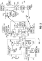
- Figure 4 is a block schematic diagram of a backchannel receiver module featured in Figures 1 and 2.
- Sense signals derived by the monitoring sections 216A, 216B are fed to a telemetry processor 222 which preferably includes a suitably-programmed microprocessor for conversion of the sense signals to a suitable telemetry signal for transmission to the central monitoring station 204.
- the telemetry processor 202 may also contain signal interface circuitry, signal processing circuitry, a power supply section, and memory sections(s) for storage and retrieval of selected information concerning the patient 218 or the operation of the MPX 210.
- the telemetry processor 222 is also programmed to perform other processing functions, such as error-checking, self-testing, and the like.
- the telemetry network data may be processed at any node on the network 205.
- the central monitoring station 204 may perform further processing so as to derive patient information and may selectively store such information in temporary or bulk storage devices 236.
- the central monitoring station 204 and may cause images indicative of such patient information to be selectively displayed on one or more displays. For instance, medical personnel that have access to the central monitoring station 204 may monitor and react to relevant physiological conditions of the patient.
- an operator can determine at the bedside what primary monitoring data is to be transmitted to the network 205 by use of an instrument telemetry configuration frame displayed on the primary monitoring instrument 201.
- Data will be transferred from the primary monitoring instrument 201 to the MPX 210, which will receive, multiplex, compress, format, and transmit the data as a telemetry signal to a telemetry signal receiving system 203.
- Receivers located in the telemetry signal receiving system 203 receive the telemetry signal and the telemetry receiver interface 233 uses appropriate protocols to convert the telemetry signal into network data messages for transmission over the network 205.
- the flexible telemetry system 200 can thereby transfer patient monitoring data, control signals, alarm signals, and other information from the MPX 210 (or an instrument connected to the MPX 210) to any node on the network, such as the node occupied by a central monitoring station 204.
- MPX 210 may be coupled to the portable processor 212 via IR transceivers in the ports 256A and 240A such that the telemetry docking station 211 need not be used.
- the two units may be physically coupled as well, to form a single, portable package.
- an optical fiber cable 244 may be connected between suitable terminals on the ports 240A, 248A, or 256A to effect light-tight transmission between I/O sections 240, 248, or 256.
- the portable processor 212 includes a data output device preferably in the form of a liquid crystal display or some other type of flat screen display 258, a data input device such as a keyboard 260, and a microprocessor section 262.
- the I/O section 256 may be operated to communicate information to and from the microprocessor 262.
- Memory sections included in the microprocessor for storing information allows the microprocessor to be programmed to perform selected processing tasks on the received data. For example, a representation of telemetry data acquired from the MPX 210 may be displayed on display 258 and the nature of this representation may be varied by a user according to commands or queries entered on the data input device 260.
- the portable processor 212 is contemplated as incorporating or accommodating other forms of data input devices such as a microphone, roller ball, touch screen, pen-based input panel, or the like. Similarly, the portable processor 212 may incorporate other forms of data output devices, such as an annunciator for sounding an audible signal, or acoustic transducer for reproducing a voice. Components for carrying out the performance of other processing tasks (not shown) may be included in the portable processor 212 as known in the art, such as extended memory cards, facsimile/modem cards, and the like.
- Keyboard inputs may be applied through I/O port 256 to I/O port 242, and from I/O port 240 to the telemetry processor 222.
- Such inputs may, for example, represent commands to change the mode of ECG monitoring by the monitor sections 216A, 216B between diagnostic and monitoring quality; if the monitor sections 216A, 216B are adapted for monitoring a variety of physiological conditions, the condition being monitored can be changed.
- the outputs from the monitoring sections 216A, 216B may be processed by the telemetry processor 222 according to commands inputted from keyboard 260.
- Data entered at keyboard 260 may also be passed through processor 262, I/O sections 256, 248, 242, and 240, and telemetry processor 222 to transmitter 224 for transmission to the central monitoring station 204.
- Such data may be utilized, for example, to effect diagnostic routines on one or more of the components of the flexible monitoring system 200.
- a backchannel receiver module 213 is detachably mounted on the MPX 210, preferably at port 240C.
- the backchannel receiver module 213 includes a communications and power port 213A, a backchannel receiver 270, and receiving antenna 272.
- Data originating from any node on the network 205 may be directed to the backchannel communications controller 214C for addressable transmission to a particular backchannel receiver module 213. That is, each message sent by backchannel transmitter 214X would include an encoded address so that it is received and/or utilized only by the backchannel receiver module 213 for which it is intended. Once received and translated, the message is provided to the I/O section 240 of the MPX 210.
- the backchannel receiver 270 may operate on an integral battery power source and alternatively may be operated via power provided through the communications and power port 213A; such power may originate from the MPX 210 or from the telemetry docking station 211.
- the requisite circuitry and components that comprise the backchannel receiver 270 and receiving antenna 272 may be constructed in a package that is extremely compact, light in weight, and consumes very little power according to known telecommunications receiver technology.
- the attachment of the backchannel receiver module 213 to the MPX 210 permits medical personnel at a node on the network 205 (e.g., a central monitoring station 204 or similar terminal) to enter information (e.g., data or commands) on an appropriate input device, and direct the information via the backchannel transmission system 214 to the MPX 210 or the portable processor 212.
- information e.g., data or commands
- Such communication may, for example, be in response to inputs or queries from attending staff that were inputted on keyboard 260.
- other monitoring instruments, data processing or storage equipment, and other control and communications equipment connected to the network 205 may communicate with the backchannel receiver module 213.
- dynamic control may be effected of the system configuration and of the patient monitoring features and functions performed by the flexible monitoring system 200. Some of such functions may heretofore have required user intervention and/or reconfiguration of one or more of components of a conventional patient monitoring system.
- dynamic control is meant to describe network-based, system-originated control of one or more of the features, functions, or tasks performed by the flexible monitoring system 200.
- Service modes such as a remote reading of: the status of the power available to the MPX 210 or telemetry docking station 211, the signal strength of the backchannel transmitter (as received by the backchannel receiver module 213), the frequency or signal strength of the transmitter 224 in the MPX 210, or the physiological conditions currently being monitored (ECG, Sp02, etc.).
- the service mode information may be acquired only on demand, so that the telemetry transmission bandwidth may be conserved for transmitting patient data.
- a particular service mode contemplated by the invention includes the transmission of new PROM code from a node on the network 205 via the backchannel transmission system 214 and the backchannel receiver module 213 for downloading into a memory device (such as an EEPROM 354 illustrated in Figure 3).
- a network node may query the MPX 210 for configuration data and settings, such as thresholds or other measurements (i.e. notch filter, Sp02 sample rate, and frequency channel) or system information (i.e. firmware/hardware revision numbers and serial number), or to view or to edit such records as a status log.
- hospital personnel may also use the portable processor 212 to receive and answer a system-initiated query, and see the system's response.
- an alarm signal e.g. a tone
- a voice signal through a transducer on the MPX 210 or portable processor 212, or by display of textual messages on the display 258 of the portable processor 212.
- Lead selection and transmitter lead fallback may be accomplished at the telemetry processor 212 before data is sent from the MPX 210. This feature also conserves the bandwidth required to transmit telemetry data, allows the MPX to transmit other parameters, or to improve forward error correction.
- Redundant transmission of information such as transmission of a waveform with 100% redundancy, thus enabling the system to compensate for dropouts in a telemetry transmission caused by multipath fading.
- Diversity selection allows a network node to command the transmitter 224 to transmit on one of two spatially separated versions of the output element 226, e.g., either an antenna integrated in the sensor 220 and another antenna imbedded in the housing of the MPX 210.
- Reuse of a selected transmission frequency by assigning a single frequency to more than one MPX 210.
- Such reuse is contemplated as being effected by spatial (cellular) allocation of a frequency, wherein each MPX 211 is located sufficiently distant from the others so as to overcome any channel interference.
- Such reuse is also contemplated as including time division multiplexing of the data transmitted from more than one MPX 211 onto one transmission channel. This feature dramatically increases the number of channels that one telemetry receiver 232 can service, and allows the flexible patient monitoring system 200 to monitor a large numbers of patients per transmission channel, and reduces errors that are caused by channel interference.
- the MPX 210 may send a message, then wait for a return message from the backchannel controller 214C acknowledging proper receipt.
- the MPX 210 may repeat the message if no acknowledgment is received.
- FIG. 3 shows an overall block diagram of a preferred embodiment of a main board 300 operable in the signal processing and data transmission section 119 of the MPX 110.
- the main board 300 may be considered to include five subsections: a set of ECG front ends, a Sp02 monitor, an application specific integrated circuit (ASIC), a digital signal processor (DSP), and a power supply section.
- ASIC application specific integrated circuit
- DSP digital signal processor
- the ASIC 310 is operable with at least four external signal interfaces (not including the output of transmitter 224).
- First and second signal interface lines 311 connect to the telemetry docking station 211; a third interface line 313 connects to a serial infrared port (SIR) 315 and the fourth interface line 314 connects to a sensor interface driver 318 (preferably in the form of a serial data port driver) which may be used to communicate to the primary monitoring instrument 201 through two leads (RA, RL) of the patient sensor (V, RA, LL, LA, RL).
- the ASIC 310 preferably contains universal asynchronous receiver-transmitters for performing these functions.
- the serial infrared port 315 communicates using a subset of the SIR protocol. This port can be "aimed" at the portable processor 212 for establishing an unguided optical communications link, or can be attached to the fiber optic cable 244 for a more robust optical connection. Such a connection facilitates the physical coupling of the portable processor 212 and the MPX 210 for combined use during ambulatory telemetry mode.
- the sensor interface 318 insures patient safety by prohibiting an electrical path from a non-battery powered instrument, such as the primary monitoring instrument 201 or auxiliary monitoring instrument 202, through the MPX 210 to the patient. Also, the sensor interface 318 will sense a voltage on one of the conductors in the connection to the primary monitoring instrument 201; the ASIC 310 will only connect a serial data driver to the patient leads when it senses this voltage. This insures that there is no harm to the patient by inadvertent application of serial data to the sensor, which may be already connected to the patient.
- An Sp02 monitoring section 321 produces data representative of the arterial oxygen saturation value, the pulse rate, and relative perfusion.
- the Sp02 monitoring section 321 will connect directly to an appropriate Sp02 sensor (not shown) such as may be obtained from Hewett-Packard Company, Nellcor, or Ohmeda.
- Additional circuitry connected to the ASIC 310 include: four ECG front ends 331, 332, 333, 334; a battery 343; a Sp02 monitor power supply circuit 344; a main power supply circuit 346; a battery sense circuit 348; a transmitter power supply circuit 352; a programmable memory storage device preferably in the form of an electrically-erasable programmable read-only memory (EEPROM) chip 354; a digital signal processor (DSP) chip 356; a static memory storage device, preferably in the form of a static random access memory (SRAM) 358; a radio-frequency (RF) modulator 362; and a radio frequency synthesizer 364.
- EEPROM electrically-erasable programmable read-only memory
- DSP digital signal processor
- the EEPROM 354 preferably contains frequency, patient identification, and system configuration information. By performing all data processing tasks in the DSP 356, which is set to by direct boot from the EEPROM 354, future software upgrades are made easily through the serial port lines 311.
- Nurse Call Button A signal on a nurse call button line 372 may be configured to cause the ASIC 310 to run a recording, set off the nurse call alarm, or perform another communication function such as what is known as spoof coding, which may be used by a technician to match a MPX 210 to a telemetry receiver 232.
- Control lines from the ASIC 310 may be operated to selectively shut down certain power subsections, as will be described below.
- a battery 343 is a Alkaline, Zinc-Air, or Carbon-Zinc 8.4 or 9 volt battery for use when the MPX 210 is not configured to monitor Sp02 ; when Sp02 is used, a lithium battery is preferred.
- the battery sense section 348 under control of the ASIC 310, effects control of all of the power supply subsections. For example, the Sp02 monitoring, transmitter, ECG monitoring, or communications functions may be individually shutdown by the ASIC 310 to conserve power.
- the ASIC 310 also provides, based on signals from the battery sense section, advance warning messages that are displayed on the network 205 or the display 258, such as "replace battery” or "weak battery”.
- the IF filtered signal is then passed to a limiter/demodulator stage 414 and a decoding stage 416.
- the decoded signal output is provided to a data transfer stage 418 for transfer through a data and power connector 420 to the MPX 210.
- a preferred embodiment of the data and power handling circuitry 502 of the telemetry docking station 211 will be understood to include : a) first and second data communication interface sections 511, 512 to enable the MPX 210 to interface with data paths from external devices (preferably, devices such as the portable processor 212 and one or more monitoring instruments, such as the primary monitoring instrument 201 and an auxiliary monitoring instrument 202); b) a power conversion section 520 and a power transformer section 622 to enable units such as the MPX 210 or portable processor 212 to receive isolated, regulated power from external power sources; and c) a data processing section 524 preferably in the form of a microprocessor for performing data protocol translation and other data interfacing functions.
- the telemetry docking station 211 preferably incorporates microminiature components and circuitry so as to provide the aforementioned functions in a compact, portable unit that is positionable adjacent, or attachable to, the portable processor 212 and/or the portable computer 114.
- a DC input power jack 504 preferably receives 12VDC from a conventional AC-to-DC wall outlet converter, certified as an IEC-601-1 medically approved device, such as are commercially available for powering portable medical electronic devices.
- a DC out jack 506 provides 12VDC to the portable processor 212.
- a first serial interface circuit 511 and a second serial interface circuit 512 have respective connections RXA, TXA and RXB, TXB. The first and second interface circuits 511, 512 are also respectively coupled to the MPX 210 via optocouplers 521, 522 and connections RX2, TX2, RX1, and TX1.
Abstract
Description
- This invention relates to patient monitoring systems and more particularly to an ambulatory patient monitoring system that is reconfigurable to facilitate the collection and use of monitored information, particularly in a hospital or other institutional setting.
- Hospitals and other medical care institutions provide differing levels of patient care so as to conserve resources, minimize the costs of patient care, and maximize patient outcomes (i.e., the condition or health of the patient). To achieve this, the attending staff will transfer a patient between different units in the hospital in accordance with the acuity of the patient's condition. For example, a high-acuity patient may be admitted to an intensive care unit (ICU) or critical care unit (CCU) then is transferred to an intermediate care unit, and so on to successively less-intensive care environments until the patient is released from the hospital. Such a paradigm of transitional medical care has been precipitated by the increasing costs of providing medical care, and the increasing acuity of the patients that receive such medical care. For example, the average acuity of the patients that are transferred to an intermediate care environment is now higher than in the past. More particularly, a patient that is transferred to an intermediate care unit is now likely to require a more intensive level of continuing care in comparison to the level of care required by such a patient in years past.
- For the attending staff to successfully practice such medical care, the patient monitoring applied to each patient must be easily reconfigured according to the patient's condition, acuity, and location. However, the conventional patient monitoring system for a non-ambulatory patient typically employs a fixed, dedicated bedside monitor that is located and dedicated for use in a bedside-monitored environment. The bedside monitor is usually wall-mounted, configured for use at one bed, and hardwired to a particular hospital communications network. Such instruments are expensive, and thus typically are in short supply, and they are not easily reconfigured when the patient transfers between beds, rooms, or environments.
- An ambulatory patient may be assigned a telemetry transmitter that is worn by the patient such that telemetry data is transmitted to an array of telemetry antennas and receivers, which are connected to the hospital communications network. Reconfiguring the patient monitoring system at transitions between non-ambulatory and ambulatory monitoring modes is a difficult, expensive, and time-consuming task, and typically results in a gap or discontinuity in the stream of monitor data. As a result, a conventional monitoring system is not well-suited for use in a transitional care practice.
- In particular, the conventional telemetry transmitter is designed to be worn by the patient so that the patient is free to move within a selected area of the hospital while still being monitored. The telemetry transmitter is made as simple, compact, and light in weight as possible. The telemetry transmitter typically lacks either a display for viewing representations of the monitored outputs or a data input device for manual entry of data. The telemetry transmitter is designed to operate independently of other monitoring instruments and offers no direct connection or interface between a monitoring instrument and the hard-wired network.
- The conventional telemetry transmitter relies solely on an internal battery for power, and as such the unit must be designed and operated to minimize battery usage. For these reasons, and also to reduce cost, the telemetry transmitter contains only a minimum of physiological monitoring devices (typically, only an electrocardiogram or ECG), a simple processor device that is programmed only to process information received from the monitoring devices and convert it into suitable form for wireless transmission, and a low-power radio frequency (RF) transmitter for outputting the processed monitor information.
- The foregoing may thus be seen to limit the versatility and usability of the telemetry transmitter, especially in situations where the telemetry transmitter is the only monitoring device applied to the patient. Such situations include:
- (a) When the telemetry transmitter is being placed on the patient, and an attendant must assure that the physiological sensors are properly mounted to provide the desired signal.
- (b) When hospital staff need to monitor routine physiological information while present in the patient's room, such as when vasoactive drugs are administered to the patient.
- (c) During installation, reconfiguration, repair, or troubleshooting of the telemetry transmitter or other components of the network.
- (d) When the patient's acuity escalates, which in some instances may be to a critical or life-threatening state, and the level of patient monitoring must be scaled up. Often, the requisite equipment (such as a defibrillator) is not proximate the patient, and yet it must be applied rapidly to the patient before the clinician can diagnose the problem and act to alleviate the problem
- (e) When a plurality of physiologic parameters must be monitored, and the telemetry transmitter is not equipped to measure all of the parameters. Typically, the additional parameter(s), such as non-invasive blood pressure (NIBP), can only be monitored by attaching other full-featured instruments (such as a bedside monitor).
- (f) When there is a need to send information from the patient's bedside to the central station, either for viewing by personnel at that station or for storage with the patient's records. Such a capability would speed the flow of data into the system and improve patient care and reduce errors. In the typical approach, such information is transcribed or downloaded from a recorder carried attending staff, or by manual data entry of handwritten notes.
- Further, while it may be desirable to implement more capabilities in a patient monitoring system so as to resolve such drawbacks, it is also desirable that such capabilities be achieved without any significant increase in the telemetry transmitter's cost, size, weight, and power usage.
- Accordingly, there is a need for a flexible patient monitoring system, which for the purposes of this application is defined as a monitoring system that: is reconfigurable, preferably by the attending staff, with minimal difficulty and disruption; accomplishes continuous monitoring of a patient even while the monitoring system is reconfigured; offers the ability to rescale the level of monitoring in accordance with changes in the patient's acuity and care environment; and offers the option of operating in either wireless or hard-wired telemetry modes.
- Accordingly, a preferred embodiment of a flexible patient monitoring system may be constructed for use in monitoring a selected plurality of physiological conditions of a patient in a medical care environment. The flexible monitoring system includes a multiport transmitter having a sensor system connectable to the patient for providing sense signals representative of the selected plurality of physiological conditions; a monitoring section for receiving the sense signal and providing first data representative of the selected plurality of physiological conditions; a first data port for receiving externally-sourced data; and a data processing and signal transmission section for processing the first data and the externally-sourced data so as to provide processed data, and for transmitting the processed data as a telemetry signal.
- In a second preferred embodiment, the flexible patient monitoring system further includes a monitoring instrument for providing the externally-sourced data. The multiport transmitter is connectable to the monitoring instrument for receiving the externally-sourced data, processing the first data and the externally-sourced data, and transmitting the processed data as a telemetry signal.
- In a third preferred embodiment, the flexible patient monitoring system further includes a telemetry subsystem interface, and the multiport transmitter is connectable to the telemetry subsystem interface for transferring data therebetween. Such transferred data may include the externally-sourced data.
- As will be described in more detail in the following description, the flexible patient monitoring system resolves a number of deficiencies found in prior art systems. For example, when it is determined that the patient is experiencing a medical emergency, readings taken by the multiport transmitter can trigger an alarm at the telemetry subsystem interface and at a network node such that the patient's condition can be viewed and utilized immediately by attending staff located both in the bedside environment and at a network node.
- When the patient's acuity increases, or otherwise indicates the need for additional monitoring instruments, such instruments may be rapidly connected to the multiport transmitter for more extensive monitoring. Thus, there need be no delay that otherwise would occur in attaching the additional monitoring instrument directly to the patient before remedial procedures are initiated. When the patient's acuity decreases, the attending staff may easily reconfigure the patient monitoring from given level of monitoring to a less-extensive level of monitoring, such as in a reconfiguration from bedside monitoring to ambulatory monitoring.
- With use of the flexible patient monitoring system taught herein, a hospital can maintain a less-extensive array of bedside connections to the network. Fewer racks of expensive monitoring equipment need be distributed about the hospital for emergencies, and the medical personnel that respond to an emergency are better informed as to which emergency equipment is needed.
- Routine procedures also benefit from the readout capability offered by the telemetry subsystem interface, thus simplifying the charting of the patient, and the diagnosis, monitoring, and treatment of the patient by attending staff and other medical personnel at the patient's bedside. Further, the contemplated patient monitoring system allows attending staff, when charting a patient, to be able to transmit readings and observations to a network node. This procedure allows recordation of readings as they are being taken, rather than by storing such information on a charting device or as handwritten notes.
- The many advantages described herein are achieved without making the multiport transmitter substantially greater in size, weight, battery use, or cost in comparison to the conventional telemetry transmitter.
- The foregoing and additional advantages of the invention will be apparent from the following detailed description of preferred embodiments of the invention as illustrated in the accompanying drawings.
- Figures 1 and 2 are simplified representations of a flexible patient monitoring system constructed in accordance with the present invention.
- Figure 3 is a block schematic diagram of a main portion of a multiport transmitter featured in Figures 1 and 2.
- Figure 4 is a block schematic diagram of a backchannel receiver module featured in Figures 1 and 2.
- Figure 5 is block schematic diagram of a telemetry docking station featured in Figures 1 and 2.
- The present invention provides increased flexibility in an improved patient monitoring system without requiring significant increase in the size, weight, cost, or battery usage of a telemetry transmitter. As will be understood with reference to Figures 1 and 2, a
telemetry subsystem 100 and a flexiblepatient monitoring system 200 may be constructed according to the present invention. Thetelemetry subsystem 100 include certain ones of the following components, depending upon the mode of patient monitoring to be performed, and the particular environment(s) in which the subsystem is operating: - a
primary monitoring instrument 101 - an
auxiliary monitoring instrument 102 - a multiport transmitter (MPX) 110
- a
telemetry docking station 111 - a telemetry subsystem interface, e.g., a
portable processor 112 orportable computer 114 - a
backchannel receiver module 113 - a
system communications network 205, which includes nodes such as acentral monitoring station 204 - a telemetry
signal receiving system 203 - a
backchannel transmission system 214 - electrocardiogram/respiration (ECG/RESP)
- electrocardiogram (ECG)
- invasive pressures
- temperature
- non-invasive blood pressure (NIBP)
- Sp0₂/Pleth level
- carbon dioxide level (CO₂)
- cardiac output
- TcGas
- A first preferred embodiment of the
backchannel receiver module 113 may be incorporated within the MPX 110 (as shown in Figure 1) or, in a second preferred embodiment, may be constructed as a detachable backchannel receiver module 213 (as shown in Figure 2). In a particularly preferred embodiment, thebackchannel receiver module backchannel transmission system 214. Suchbackchannel transmission system 214 includes abackchannel controller 214C,backchannel transmitter 214X, andantenna 214A. - The telemetry subsystem interface is preferably provided in the form of a
portable processor 112, or aportable computer 114. A preferred embodiment of theportable processor 112 is a Hewlett-Packard 200LX palmtop processor. Theportable computer 114 is preferably provided in the form of a notebook computer. A preferred embodiment of theportable computer 114 is a Hewlett-Packard Omnibook superportable computer. - Application software resident on the
portable processor 112 orportable computer 114 provides control and interfacing functions with respect to theMPX 110 transmitter. Software for operating theportable processor 112 or theportable computer 114 may be installed via a plug-in memory module, preferably in the form of a memory card C (such as a PCMCIA card). For example, theportable processor 112 can initiate communication with theMPX 110 transmitter automatically upon program execution and establishment of a communication link for transfer of control and data signals. The contemplated communications link may be effected through a first data port, preferably in the form of anoptical communications transceiver 121 via light beam L, or via anoptical fiber cable 122. Alternatively, a communications link may be effected at a second data port preferably in the form of aserial data interface 123 coupled to a data portion of a multiconductor data and power cable 123A. Power may be transferred to theportable processor 112 via a power cable portion of the multiconductor data andpower cable 123A to aDC input jack 124. - A first preferred embodiment of the
telemetry docking station 111 includes a first data andpower port 120B for connecting power lines P and data paths D1, D2 between thetelemetry docking station 111 and theMPX 110. Power may be supplied to thetelemetry docking station 111 from a permanent power source (e.g., an AC outlet) via an AC/DC converter 125 through apower conditioning circuit 126 and anisolation circuit 127. Additional power lines P and a data path D3 are connected to theportable processor 112 orportable computer 114 via a second data andpower port 128. An additional data path D4 is connected to theprimary monitoring instrument 101 orauxiliary monitoring instrument 102 via afirst data port 132 to which a monitoringinstrument multiconductor cable multiconductor cables - The
isolation circuit 127 provides isolated, conditioned power to theMPX 110,portable processor 112, andportable computer 114, thus providing reliable, isolated power and relieving those units from the need to operate on other power sources, such as internal batteries. Theisolation circuit 127 also provides electrically-isolated transfer of data between theMPX 110,portable processor 112 orportable computer 114, theprimary monitoring instrument 101, and theauxiliary monitoring instrument 102. For portability, thetelemetry docking station 111 is preferably provided in a compact, light, low-profile form factor similar to that of the portable processor 112 (e.g., of dimensions less than or comparable to that of the interior of a coat pocket, at approximately 16 x 9 x 3 centimeters). - As particularly illustrated in Figure 2, a second preferred embodiment of the MPX 210 contains first and second
physiological monitoring sections physiological monitoring section 216A may be connected to thepatient 218 by asensor 220. For example, for ECG monitoring, thesensor 220 would be connected to electrodes attached to the patient's chest. As will be described below, a certain ones of the conductors insensor 220 may also be employed as a data communications link 220A to aprimary monitoring instrument 201. - Sense signals derived by the
monitoring sections telemetry processor 222 which preferably includes a suitably-programmed microprocessor for conversion of the sense signals to a suitable telemetry signal for transmission to thecentral monitoring station 204. Thetelemetry processor 202 may also contain signal interface circuitry, signal processing circuitry, a power supply section, and memory sections(s) for storage and retrieval of selected information concerning thepatient 218 or the operation of the MPX 210. Thetelemetry processor 222 is also programmed to perform other processing functions, such as error-checking, self-testing, and the like. - A telemetry signal is output from the
telemetry processor 222 to a frequency-synthesized transmitter 224 for broadcast at asuitable output element 226. Depending on the telemetry needs in the hospital, the transmitter 224 andoutput element 226 may be constructed to radiate at a selected frequency in the radio frequency (RF) band; theoutput element 226 may be integrated into thesensor 220 or may be otherwise situated in the MPX 210. An alternative embodiment of the transmitter 224 andoutput element 226 may be constructed to radiate at a selected frequency in the optical transmission band, for example, an infrared frequency. - The telemetry signal emitted by the
output element 226 is received by one of a plurality of receivingelements 228 andtelemetry receivers 232 suitably located in the hospital. Telemetry signals acquired by the plurality oftelemetry receivers 232 are applied to atelemetry receiver interface 233 for translation to network telemetry data, which is transferred to anetwork controller 230 preferably in the form of a serial communications controller (SCC). The network telemetry data is then transferable to other nodes on thenetwork 205 such as thecentral station 204. Such nodes may be considered local nodes, that is, in locations proximate to thepatient 218, and other nodes may be quite remotely situated. The local nodes on thenetwork 205 are contemplated as including suitable data terminals, workstations, and the like so as to make the network telemetry data available to hospital staff at a network node in a clinical or surgical setting, a physician's office, a hospital pharmacy, a diagnostic laboratory, a data processing and record-keeping center, and similar departments or locations within the hospital. Additional password-protected, secure connections to communications networks outside the hospital, such as telephone and radio networks, allow authorized persons to access the network telemetry data at remote nodes (i.e., nodes located outside of the hospital). - The telemetry network data may be processed at any node on the
network 205. For instance, thecentral monitoring station 204 may perform further processing so as to derive patient information and may selectively store such information in temporary orbulk storage devices 236. Thecentral monitoring station 204 and may cause images indicative of such patient information to be selectively displayed on one or more displays. For instance, medical personnel that have access to thecentral monitoring station 204 may monitor and react to relevant physiological conditions of the patient. - The MPX 210 features an input/output (I/O)
section 240 that operates first, second, andthird ports 240A, 240B, 240C. The first port 240A may, for example, be a wireless transceiver data port, such as one including an IR transmitter and complying with the serial infrared (SIR) data transmission protocol designed by the Hewlett-Packard Company. Such a first port would interface with one or more SIR receivers present on theportable processor 212 as described above. The second port 240B may be directly connected to thetelemetry docking station 211 at arespective port 242A and serve as a power and data communications interface between the MPX 210 and thetelemetry docking station 211. Thethird port 240C may connect to abackchannel receiver module 213 as will be discussed below. - The
telemetry docking station 211 includes a first, second, and third I/O sections respective ports power isolation section 250 and apower conditioning section 252 are connectable to a permanent power source (not shown) such as the hospital main electrical system. The second I/O section 246 serves as a data interface to anauxiliary monitoring instrument 202. The third I/O section 248 andport 248A serve as a data interface operable with an I/O section 256 andport 256A on theportable processor 212. Preferably, theports - The flexible
patient monitoring system 200 may be configured to operate in at least four modes: - 1) ambulatory telemetry mode, wherein the MPX 210 is operated independently of other monitoring instruments and is powered by an internal power source;
- 2) docked telemetry mode, wherein the MPX 210 is connected to a
telemetry docking station 211 for transfer of data and power; - 3) simple instrument telemetry mode, wherein the MPX 210 and a
primary monitoring instrument 201 or anauxiliary monitoring instrument 202 are connected together for transfer of data therebetween, and - 4) docked instrument telemetry mode, wherein the MPX 210 and a
primary monitoring instrument 201 or anauxiliary monitoring instrument 202 are attached to thetelemetry docking station 211 for transfer of data therebetween (and optionally for transfer of power to the MPX 210). - For example, when the MPX 210 is operated in the instrument telemetry mode, an operator can determine at the bedside what primary monitoring data is to be transmitted to the
network 205 by use of an instrument telemetry configuration frame displayed on theprimary monitoring instrument 201. Data will be transferred from theprimary monitoring instrument 201 to the MPX 210, which will receive, multiplex, compress, format, and transmit the data as a telemetry signal to a telemetrysignal receiving system 203. Receivers located in the telemetrysignal receiving system 203 receive the telemetry signal and thetelemetry receiver interface 233 uses appropriate protocols to convert the telemetry signal into network data messages for transmission over thenetwork 205. Theflexible telemetry system 200 can thereby transfer patient monitoring data, control signals, alarm signals, and other information from the MPX 210 (or an instrument connected to the MPX 210) to any node on the network, such as the node occupied by acentral monitoring station 204. - In particular, the MPX 210 can provide a wireless connection of the
portable processor 212, theportable computer 114, theprimary monitoring instrument 201, and/or theauxiliary monitoring instrument 202 to thenetwork 205. Further, data received by theMPX 110 from theportable processor 212, theportable computer 114, theprimary monitoring instrument 201, and/or theauxiliary monitoring instrument 202 may be monitored at the patient's location, without any need for a hard-wired network connection. - Due to its multiplicity of communication ports, the MPX 210 may be easily reconfigured to and from ambulatory mode, docked telemetry mode, simple instrument telemetry mode, or docked instrument telemetry mode. This flexibility allows the flexible
patient monitoring system 200 to be reconfigured while thepatient 218 occupies or moves between any of the hospital areas that are serviced by receivingelements 228. This reconfiguration may be accomplished while still permitting continuous monitoring of relevant patient physiological conditions. As a result, the task of patient monitoring is effected more flexibly and inexpensively, patient bed transfer costs are reduced, and the number and acuity of the patients that are monitored is greater than in a conventional patient monitoring system. - Preferably, the telemetry signal contains status information pertaining to the monitoring mode as well as the type of data being transmitted. The telemetry
signal receiving system 203 includes data acquisition software modules for determining whether the data received is ambulatory telemetry data or instrument telemetry data, and formatting the received telemetry data into a form appropriate for transmission on the network. For instance, thecentral monitoring station 204 may receive telemetry data that has been formatted to cause differing user interfaces to be displayed on the central monitoring station, according to whether the data represents information derived from an ambulatory telemetry mode or an instrument telemetry mode. As a further example, recording requests from theprimary monitoring instrument 201 may be formatted into the various types of recordings supported by different nodes of thenetwork 205. - In some instances of ambulatory mode operation, it may be advantageous to couple the MPX 210 to the
portable processor 212 via IR transceivers in theports 256A and 240A such that thetelemetry docking station 211 need not be used. The two units (MPX 210 and portable processor 212) may be physically coupled as well, to form a single, portable package. When necessary, anoptical fiber cable 244 may be connected between suitable terminals on theports O sections - The
portable processor 212 includes a data output device preferably in the form of a liquid crystal display or some other type offlat screen display 258, a data input device such as akeyboard 260, and amicroprocessor section 262. The I/O section 256 may be operated to communicate information to and from themicroprocessor 262. Memory sections included in the microprocessor for storing information allows the microprocessor to be programmed to perform selected processing tasks on the received data. For example, a representation of telemetry data acquired from the MPX 210 may be displayed ondisplay 258 and the nature of this representation may be varied by a user according to commands or queries entered on thedata input device 260. The user may select from a variety of a representations, including ECG waveforms, a transmitter frequency chart, trend graphs, or other useful information. While not specifically indicated in Figure 2, theportable processor 212 is contemplated as incorporating or accommodating other forms of data input devices such as a microphone, roller ball, touch screen, pen-based input panel, or the like. Similarly, theportable processor 212 may incorporate other forms of data output devices, such as an annunciator for sounding an audible signal, or acoustic transducer for reproducing a voice. Components for carrying out the performance of other processing tasks (not shown) may be included in theportable processor 212 as known in the art, such as extended memory cards, facsimile/modem cards, and the like. - Keyboard inputs, either as generated, or as modified by
processor 262, may be applied through I/O port 256 to I/O port 242, and from I/O port 240 to thetelemetry processor 222. Such inputs may, for example, represent commands to change the mode of ECG monitoring by themonitor sections monitor sections monitoring sections telemetry processor 222 according to commands inputted fromkeyboard 260. Data entered atkeyboard 260 may also be passed throughprocessor 262, I/O sections telemetry processor 222 to transmitter 224 for transmission to thecentral monitoring station 204. Such data may be utilized, for example, to effect diagnostic routines on one or more of the components of theflexible monitoring system 200. - A
backchannel receiver module 213 is detachably mounted on the MPX 210, preferably atport 240C. Thebackchannel receiver module 213 includes a communications andpower port 213A, abackchannel receiver 270, and receivingantenna 272. Data originating from any node on thenetwork 205 may be directed to thebackchannel communications controller 214C for addressable transmission to a particularbackchannel receiver module 213. That is, each message sent bybackchannel transmitter 214X would include an encoded address so that it is received and/or utilized only by thebackchannel receiver module 213 for which it is intended. Once received and translated, the message is provided to the I/O section 240 of the MPX 210. - The
backchannel receiver 270 may operate on an integral battery power source and alternatively may be operated via power provided through the communications andpower port 213A; such power may originate from the MPX 210 or from thetelemetry docking station 211. The requisite circuitry and components that comprise thebackchannel receiver 270 and receivingantenna 272 may be constructed in a package that is extremely compact, light in weight, and consumes very little power according to known telecommunications receiver technology. - The attachment of the
backchannel receiver module 213 to the MPX 210 permits medical personnel at a node on the network 205 (e.g., acentral monitoring station 204 or similar terminal) to enter information (e.g., data or commands) on an appropriate input device, and direct the information via thebackchannel transmission system 214 to the MPX 210 or theportable processor 212. Such communication may, for example, be in response to inputs or queries from attending staff that were inputted onkeyboard 260. Similarly, other monitoring instruments, data processing or storage equipment, and other control and communications equipment connected to thenetwork 205 may communicate with thebackchannel receiver module 213. - As mentioned in the above, the particularly preferred embodiment of the
backchannel receiver module 213 is constructed to support a communications backchannel via a paging transmission system. Most communities already employ one or more "wide-area" paging transmission systems to communicate with portable, pocket-sized receivers known as pagers. Accordingly, thebackchannel receiver module 213 is constructed to take advantage of any pre-existing paging transmission system so as to provide inexpensive, two-way communication between thenetwork 205 and the MPX 210. In particular, most hospitals already employ at least one "local-area" paging system that has been installed and dedicated for hospital use, and many hospital staff members carry a pager. Because the hospital staff members are already carryingportable processors 212 andportable computers 114 for other purposes, and will increasingly do so in the future, the benefits of the present invention are achieved without the significant expense of additional equipment and without any significant change in the way such hospitals and personnel are already operating. - Further, it is a particular feature of the present invention that dynamic control may be effected of the system configuration and of the patient monitoring features and functions performed by the
flexible monitoring system 200. Some of such functions may heretofore have required user intervention and/or reconfiguration of one or more of components of a conventional patient monitoring system. For the purposes of this description, dynamic control is meant to describe network-based, system-originated control of one or more of the features, functions, or tasks performed by theflexible monitoring system 200. Such features, functions, or tasks include:
Service modes, such as a remote reading of: the status of the power available to the MPX 210 ortelemetry docking station 211, the signal strength of the backchannel transmitter (as received by the backchannel receiver module 213), the frequency or signal strength of the transmitter 224 in the MPX 210, or the physiological conditions currently being monitored (ECG, Sp0₂, etc.). The service mode information may be acquired only on demand, so that the telemetry transmission bandwidth may be conserved for transmitting patient data. A particular service mode contemplated by the invention includes the transmission of new PROM code from a node on thenetwork 205 via thebackchannel transmission system 214 and thebackchannel receiver module 213 for downloading into a memory device (such as anEEPROM 354 illustrated in Figure 3). - Query the MPX Configuration, wherein a network node may query the MPX 210 for configuration data and settings, such as thresholds or other measurements (i.e. notch filter, Sp0₂ sample rate, and frequency channel) or system information (i.e. firmware/hardware revision numbers and serial number), or to view or to edit such records as a status log. Alternatively, hospital personnel may also use the
portable processor 212 to receive and answer a system-initiated query, and see the system's response. - Delivery of alarms or messages to the patient or attending staff by provision of an alarm signal (e.g. a tone) or a voice signal through a transducer on the MPX 210 or
portable processor 212, or by display of textual messages on thedisplay 258 of theportable processor 212. - Determination of the location of the MPX (and hence location of the patient) via transmission of signals from a plurality of
backchannel transmission systems 214 each of which are spatially separated at fixed, known locations within the hospital, followed by measurement of the strength and delay of the signals. - Lead selection and transmitter lead fallback may be accomplished at the
telemetry processor 212 before data is sent from the MPX 210. This feature also conserves the bandwidth required to transmit telemetry data, allows the MPX to transmit other parameters, or to improve forward error correction. - Redundant transmission of information, such as transmission of a waveform with 100% redundancy, thus enabling the system to compensate for dropouts in a telemetry transmission caused by multipath fading.
- Dynamic power control of the radiated power level of the transmitter 224, according to the transmission path power loss. Rather than transmitting at a high enough power to overcome worst case losses, activation of this feature allows the average power consumption to be minimized, thus substantially extending battery life.
- Diversity selection allows a network node to command the transmitter 224 to transmit on one of two spatially separated versions of the
output element 226, e.g., either an antenna integrated in thesensor 220 and another antenna imbedded in the housing of the MPX 210. - Reuse of a selected transmission frequency by assigning a single frequency to more than one MPX 210. Such reuse is contemplated as being effected by spatial (cellular) allocation of a frequency, wherein each
MPX 211 is located sufficiently distant from the others so as to overcome any channel interference. Such reuse is also contemplated as including time division multiplexing of the data transmitted from more than oneMPX 211 onto one transmission channel. This feature dramatically increases the number of channels that onetelemetry receiver 232 can service, and allows the flexiblepatient monitoring system 200 to monitor a large numbers of patients per transmission channel, and reduces errors that are caused by channel interference. - Selection of the transmission frequency (transmission channel), an otherwise costly and time consuming process, so as to change the frequency of the transmitter 224 without user intervention.
- Error control according to data exchange protocols so as to correct short term dropouts (due to multipath fading). For example, the MPX 210 may send a message, then wait for a return message from the
backchannel controller 214C acknowledging proper receipt. The MPX 210 may repeat the message if no acknowledgment is received. - Figure 3 shows an overall block diagram of a preferred embodiment of a
main board 300 operable in the signal processing anddata transmission section 119 of theMPX 110. Themain board 300 may be considered to include five subsections: a set of ECG front ends, a Sp0₂ monitor, an application specific integrated circuit (ASIC), a digital signal processor (DSP), and a power supply section. - The
ASIC 310 is operable with at least four external signal interfaces (not including the output of transmitter 224). First and secondsignal interface lines 311 connect to thetelemetry docking station 211; a third interface line 313 connects to a serial infrared port (SIR) 315 and the fourth interface line 314 connects to a sensor interface driver 318 (preferably in the form of a serial data port driver) which may be used to communicate to theprimary monitoring instrument 201 through two leads (RA, RL) of the patient sensor (V, RA, LL, LA, RL). TheASIC 310 preferably contains universal asynchronous receiver-transmitters for performing these functions. - The serial
infrared port 315 communicates using a subset of the SIR protocol. This port can be "aimed" at theportable processor 212 for establishing an unguided optical communications link, or can be attached to thefiber optic cable 244 for a more robust optical connection. Such a connection facilitates the physical coupling of theportable processor 212 and the MPX 210 for combined use during ambulatory telemetry mode. - In a particular feature of the invention, the
sensor interface 318 insures patient safety by prohibiting an electrical path from a non-battery powered instrument, such as theprimary monitoring instrument 201 orauxiliary monitoring instrument 202, through the MPX 210 to the patient. Also, thesensor interface 318 will sense a voltage on one of the conductors in the connection to theprimary monitoring instrument 201; theASIC 310 will only connect a serial data driver to the patient leads when it senses this voltage. This insures that there is no harm to the patient by inadvertent application of serial data to the sensor, which may be already connected to the patient. - An
Sp0₂ monitoring section 321 produces data representative of the arterial oxygen saturation value, the pulse rate, and relative perfusion. TheSp0₂ monitoring section 321 will connect directly to an appropriate Sp0₂ sensor (not shown) such as may be obtained from Hewett-Packard Company, Nellcor, or Ohmeda. - Additional circuitry connected to the
ASIC 310 include: four ECG front ends 331, 332, 333, 334; a battery 343; a Sp0₂ monitorpower supply circuit 344; a mainpower supply circuit 346; abattery sense circuit 348; a transmitterpower supply circuit 352; a programmable memory storage device preferably in the form of an electrically-erasable programmable read-only memory (EEPROM)chip 354; a digital signal processor (DSP) chip 356; a static memory storage device, preferably in the form of a static random access memory (SRAM) 358; a radio-frequency (RF)modulator 362; and aradio frequency synthesizer 364. Also connected to theASIC 310 are a set of leads-off indicators, each preferably in the form of a light-emitting diode (LED)array 366, and a RLlead driver circuit 368. TheASIC 310 handles the task of interfacing to the ECG hardware, the nurse call button, the leads off indicators; and theASIC 310 controls signals to and from theSp0₂ circuit 321, theprimary monitoring instrument 201, theSIR port 315, and the two serial port lines 311. - The
EEPROM 354 preferably contains frequency, patient identification, and system configuration information. By performing all data processing tasks in the DSP 356, which is set to by direct boot from theEEPROM 354, future software upgrades are made easily through the serial port lines 311. - Additional main board hardware architecture includes:
Nurse Call Button: A signal on a nursecall button line 372 may be configured to cause theASIC 310 to run a recording, set off the nurse call alarm, or perform another communication function such as what is known as spoof coding, which may be used by a technician to match a MPX 210 to atelemetry receiver 232. - Power Supply Control: Control lines from the
ASIC 310 may be operated to selectively shut down certain power subsections, as will be described below. - Internal Power Source: Preferably, a battery 343 is a Alkaline, Zinc-Air, or Carbon-Zinc 8.4 or 9 volt battery for use when the MPX 210 is not configured to monitor Sp0₂ ; when Sp0₂ is used, a lithium battery is preferred.
- Visual indicators: Five indicators preferably in the form of
light emitting diodes 366 are situated on the exterior of the MPX 210 with each indicator located under the respective electrode that corresponds to a lead. TheDSP 342 activates an appropriate indicator after a change of state (e.g., leads-off condition) in any lead wire. Also, some or all of the LEDs may be activated in a predetermined pattern to indicate that the MPX fails a self-test, or to indicate the signal strength received by theSIR 315. - Power Supply: The main
power supply section 346 is a linear or switch mode power supply that converts power from the battery 343 for provision to the Sp0₂power supply subsection 344, transmitterpower supply subsection 352, andbattery sense subsection 348. Additionally, the MPX 210 may source power from thetelemetry docking station 211 or thesensor 220 via diodes that are connected to the mainpower supply section 346. For example, when theprimary monitoring instrument 201 is employed in instrument telemetry mode and power from the battery 343 is to be conserved, the presence of a minimum of 9V on the shield of the RL lead causes themain power supply 346 to draw its power from thesensor 220. Patient isolation is achieved by preventing simultaneous connections to both the patient and to power from theprimary monitoring instrument 201
Battery Sense Section: Thebattery sense section 348, under control of theASIC 310, effects control of all of the power supply subsections. For example, the Sp0₂ monitoring, transmitter, ECG monitoring, or communications functions may be individually shutdown by theASIC 310 to conserve power. TheASIC 310 also provides, based on signals from the battery sense section, advance warning messages that are displayed on thenetwork 205 or thedisplay 258, such as "replace battery" or "weak battery". - Figure 4 illustrates a particularly preferred
embodiment 402 of thebackchannel receiver module 213 of Figure 2. The pagingbackchannel receiver module 402 preferably receives frequency-modulated (FM) transmissions at certain paging transmission frequencies, which currently include frequencies in the range of 30 -50 megahertz (mHz), 150-174 mHz, 450-512 mHz, or 800-1000 mHz. These transmissions are received by an antenna 604 that is preferably integrally mounted on thebackchannel receiver module 402, and filtered by aRF filter stage 406 before being passed to amixer 408. The output of anoscillator 410 mixed with the filtered RF signal is output to an intermediate frequency (IF)filter stage 412. The IF filtered signal is then passed to a limiter/demodulator stage 414 and adecoding stage 416. The decoded signal output is provided to adata transfer stage 418 for transfer through a data and power connector 420 to the MPX 210. - With reference to Figure 5, a preferred embodiment of the data and power handling circuitry 502 of the
telemetry docking station 211 will be understood to include : a) first and second datacommunication interface sections portable processor 212 and one or more monitoring instruments, such as theprimary monitoring instrument 201 and an auxiliary monitoring instrument 202); b) apower conversion section 520 and apower transformer section 622 to enable units such as the MPX 210 orportable processor 212 to receive isolated, regulated power from external power sources; and c) adata processing section 524 preferably in the form of a microprocessor for performing data protocol translation and other data interfacing functions. Thetelemetry docking station 211 preferably incorporates microminiature components and circuitry so as to provide the aforementioned functions in a compact, portable unit that is positionable adjacent, or attachable to, theportable processor 212 and/or theportable computer 114. - A DC
input power jack 504 preferably receives 12VDC from a conventional AC-to-DC wall outlet converter, certified as an IEC-601-1 medically approved device, such as are commercially available for powering portable medical electronic devices. A DC out jack 506 provides 12VDC to theportable processor 212. A firstserial interface circuit 511 and a secondserial interface circuit 512 have respective connections RXA, TXA and RXB, TXB. The first andsecond interface circuits optocouplers - The received 12VDC power from the charger is passed through first and second
linear regulators oscillator 534 and to first and second field-effect transistor (FET) stages 536, 538 before being fed to the primary sides of first andsecond transformers Linear regulators transformers
8V -- transformer primaries
5V -- power tooscillator 534
8VA - isolated power to the MPX 210
5VA - isolated power to local side ofoptocouplers
5VB - Isolated power to remote side ofoptocoupler 521
5VC - Isolated power to remote side ofoptocoupler 522
This illustrated circuit uses thetransformers telemetry docking station 211 thus provides these features: - a. power line isolation by the use of an IEC-601-1 medically-approved wall charger;
- b. patient isolation by use of isolated power supplies;.
- c. serial data optical isolation;
- d. defibrillation isolation, by employing recessed pins in all external connectors on the MPX 210.
- While the invention has been particularly shown and described above with reference to preferred embodiments, changes in form and detail may be made by one skilled in the art to the foregoing embodiments without departing from the spirit and scope of the invention.
Claims (10)
- A flexible patient monitoring system (200) for use in monitoring a selected plurality of physiological conditions of a patient in a medical care environment, comprising:
a multiport transmitter (210) including:
a sensor system (220) connectable to the patient for providing a sense signal representative of the selected plurality of physiological conditions;
a monitoring section (216A, 216B) for receiving the sense signal and providing first data representative of the plurality of physiological conditions,
a first data port (240A) for receiving externally-sourced data; and
a data processing and signal transmission section (222, 224) for processing the first data and the externally-sourced data so as to provide processed data, and for transmitting the processed data as a telemetry signal. - The flexible patient monitoring system (200) of claim 1, further comprising a monitoring instrument (201, 202), wherein the first data port (240A) or the sensor system (220) is connectable to the monitoring instrument for receiving said externally-sourced data.
- The flexible patient monitoring system (200) of claim 1, wherein the processed data is provided for output at the first data port (240A), and further comprising a telemetry subsystem interface (212) having a data input device (260), a data output device (258), an interface data input/output section (256) and a second data port (256A) associated therewith, and a processor (262), wherein the first and second data ports (240A, 256A) are connectable for transfer of the processed data and the processor (262) is operable for receiving the processed data and selectably outputting the processed data on the data output device (258).
- The flexible patient monitoring system (200) of claim 1, wherein the multiport transmitter (210) includes a third data port (240B) for receiving said externally-sourced data and for outputting said processed data, and further comprising a telemetry docking station (211) having a fourth data port (242A) connectable to the third data port (240B) for transferring said externally-sourced data and said processed data therebetween.
- The flexible patient monitoring system (200) of claim 4, wherein the multiport transmitter (210) further comprises a first power port (240B) for receiving operating power, and wherein the telemetry docking station (211) further comprises:
a power section (252) for receiving externally-sourced power;
an isolation section (250) having a power converter for converting the externally-sourced power to isolated power;
a second power port (242A) connectable to the first power port (240B) for transferring isolated power therebetween; and
a fifth data port (246A) for receiving said externally-sourced data,
and wherein the isolation section (250) further comprises a data isolator for receiving and isolating the externally-sourced data. - The flexible patient monitoring system (200) of claim 5, further comprising a monitoring instrument (201, 202) or a telemetry subsystem interface (212) and wherein the fifth data port (246A) is connectable to the monitoring instrument (201, 202) or the telemetry subsystem interface (212) for receiving said externally-sourced data.
- The flexible patient monitoring system (200) of claim 1, further comprising:
a telemetry receiving system (203) for receiving and processing the telemetry signal so as to provide telemetry information;
a network controller (230) for providing networked telemetry information; and
a communications network (205) having a first node connected to the network controller (230) for receiving the networked telemetry information an a second node connected to an information access device (236) for accessing the networked telemetry information. - A flexible patient monitoring system (200) for use in monitoring a selected plurality of physiological conditions of a patient (218) in a medical care environment, the system comprising:
a monitoring instrument (201, 202) for monitoring at least one of said selected plurality of physiological parameters and providing a respective monitoring instrument signal;
a multiport transmitter (210) connectable to the patient (218) for receiving first data representative of the selected plurality of the physiological conditions, and connectable to the monitoring instrument (201, 202) for receiving externally-sourced data, wherein the multiport transmitter (210) includes a data processing and signal transmission section (222, 224) for processing the first data and the externally-sourced data so as to provide processed data, and transmitting the processed data as a telemetry signal; and
a telemetry docking station (211) connectable to the monitoring instrument (201,202) and the multiport transmitter (210);
wherein the flexible patient monitoring system (200) may be configured to operate in at least four modes: ambulatory telemetry mode, wherein the multiport transmitter (210) is operated independently of the monitoring instrument (201,202) and is powered by an internal power source; docked telemetry mode, wherein the multiport transmitter (210) is connected to the telemetry docking station (211) for transfer of data and power therebetween; simple instrument telemetry mode, wherein the multiport transmitter (210) and the monitoring instrument (201, 202) are connected together for transfer of data; and docked instrument telemetry mode, wherein the multiport transmitter (210) and the monitoring instrument (201,202) are attached to the telemetry docking station (211) for transfer data therebetween. - The flexible patient monitoring system (200) of claim 14, further comprising a telemetry subsystem interface (212), and wherein the multiport transmitter (210) or the telemetry docking station (211) is connectable to the telemetry subsystem interface (212) for transferring said externally-sourced data and said processed data therebetween.
- A multiport transmitter (210) in a flexible patient monitoring system (200) for use in monitoring a selected plurality of physiologicl conditions of a patient (218) in a medical care environment, the system including a monitoring instrument (201,202) for monitoring at least one of said selected plurality of physiological parameters and providing a respective monitoring instrument signal, comprising:
a sensor (220) being connectable in a first mode to the monitoring instrument (201,202) for acquiring the monitoring instrument signal, and in a second mode to the patient for acquiring a patient parameter signal;
a first monitoring section (216A) for receiving the patient parameter signal and providing a conditioned signal in response;
a sensor interface operable in the first mode for selecting the instrument monitored signal from the sensor (220) and in a second mode for selecting the patient parameter signal from the sensor (220), and in response providing a selected monitor signal;
a data input port for receiving externally-sourced data;
a processing section (222) for processing the selected monitor signal and the externally-sourced data, and for providing, in response to said processing, processed data;
a data output port for outputting the processed data; and
a radio frequency transmitter (224) for transmitting the processed data as a telemetry signal.
Applications Claiming Priority (2)
| Application Number | Priority Date | Filing Date | Title |
|---|---|---|---|
| US08/326,614 US5687734A (en) | 1994-10-20 | 1994-10-20 | Flexible patient monitoring system featuring a multiport transmitter |
| US326614 | 1994-10-20 |
Publications (3)
| Publication Number | Publication Date |
|---|---|
| EP0707825A2 true EP0707825A2 (en) | 1996-04-24 |
| EP0707825A3 EP0707825A3 (en) | 1998-11-25 |
| EP0707825B1 EP0707825B1 (en) | 2000-12-13 |
Family
ID=23272967
Family Applications (1)
| Application Number | Title | Priority Date | Filing Date |
|---|---|---|---|
| EP95111112A Expired - Lifetime EP0707825B1 (en) | 1994-10-20 | 1995-07-14 | Flexible patient monitoring system |
Country Status (4)
| Country | Link |
|---|---|
| US (1) | US5687734A (en) |
| EP (1) | EP0707825B1 (en) |
| JP (1) | JP4121568B2 (en) |
| DE (1) | DE69519619T2 (en) |
Cited By (34)
| Publication number | Priority date | Publication date | Assignee | Title |
|---|---|---|---|---|
| WO1998011820A1 (en) * | 1996-09-19 | 1998-03-26 | Ortivus Aktiebolag | Portable telemedicin device |
| EP0938909A1 (en) * | 1997-12-15 | 1999-09-01 | Siemens-Elema AB | Ventilator system |
| EP1099407A2 (en) * | 1999-11-11 | 2001-05-16 | GE Medical Systems Information Technologies, Inc. | Portable patient monitor with antenna integrated into handle |
| WO2002007816A1 (en) * | 2000-07-24 | 2002-01-31 | Lifecor, Inc. | Data collection and system management for patient-worn medical devices |
| EP1191877A1 (en) * | 1999-05-06 | 2002-04-03 | Shell, Allan Michael | Physiological signal acquisition cable |
| WO2003022142A3 (en) * | 2001-09-13 | 2003-10-16 | Boeing Co | Method for transmitting vital health statistics to a remote location form an aircraft |
| US6681003B2 (en) | 1999-10-05 | 2004-01-20 | Lifecor, Inc. | Data collection and system management for patient-worn medical devices |
| DE102007057169A1 (en) | 2007-11-26 | 2009-05-28 | Helmut Rauer | Diagnostic machine for web-based sensor- and evaluation system, has personal-computer-based processor, where machine supplies processed data into diagnostic- and management center over secured internet connection |
| US7689437B1 (en) | 2000-06-16 | 2010-03-30 | Bodymedia, Inc. | System for monitoring health, wellness and fitness |
| US8157731B2 (en) | 2002-10-09 | 2012-04-17 | Bodymedia, Inc. | Method and apparatus for auto journaling of continuous or discrete body states utilizing physiological and/or contextual parameters |
| US8275635B2 (en) | 2007-02-16 | 2012-09-25 | Bodymedia, Inc. | Integration of lifeotypes with devices and systems |
| US8369936B2 (en) | 2003-09-12 | 2013-02-05 | Bodymedia, Inc. | Wearable apparatus for measuring heart-related parameters and deriving human status parameters from sensed physiological and contextual parameters |
| US8398546B2 (en) | 2000-06-16 | 2013-03-19 | Bodymedia, Inc. | System for monitoring and managing body weight and other physiological conditions including iterative and personalized planning, intervention and reporting capability |
| US8403845B2 (en) | 1999-10-18 | 2013-03-26 | Bodymedia, Inc. | Wearable human physiological and environmental data sensors and reporting system therefor |
| US8405608B2 (en) | 1999-01-25 | 2013-03-26 | Masimo Corporation | System and method for altering a display mode |
| US8532727B2 (en) | 1999-01-25 | 2013-09-10 | Masimo Corporation | Dual-mode pulse oximeter |
| US8663106B2 (en) | 2002-08-22 | 2014-03-04 | Bodymedia, Inc. | Non-invasive temperature monitoring device |
| US8961413B2 (en) | 2000-06-16 | 2015-02-24 | Bodymedia, Inc. | Wireless communications device and personal monitor |
| US8961414B2 (en) | 2000-06-16 | 2015-02-24 | Aliphcom | Apparatus for monitoring health, wellness and fitness |
| US8965500B2 (en) | 2007-06-06 | 2015-02-24 | Zoll Medical Corporation | Wearable defibrillator with audio input/output |
| US9168001B2 (en) | 2002-08-22 | 2015-10-27 | Bodymedia, Inc. | Adhesively mounted apparatus for determining physiological and contextual status |
| US9204813B2 (en) | 2011-03-25 | 2015-12-08 | Zoll Medical Corporation | Method of detecting signal clipping in a wearable ambulatory medical device |
| US9408548B2 (en) | 2011-03-25 | 2016-08-09 | Zoll Medical Corporation | Selection of optimal channel for rate determination |
| US9763581B2 (en) | 2003-04-23 | 2017-09-19 | P Tech, Llc | Patient monitoring apparatus and method for orthosis and other devices |
| EP3363349A1 (en) * | 2016-08-25 | 2018-08-22 | seca ag | Measuring device for determining physiological values of a patient and sensor unit |
| US10252070B2 (en) | 2015-09-08 | 2019-04-09 | Zoll Medical Corporation | Secure limited components for use with medical devices |
| US10426342B2 (en) | 2016-03-31 | 2019-10-01 | Zoll Medical Corporation | Remote access for ambulatory medical device |
| US10565396B2 (en) | 2016-03-30 | 2020-02-18 | Zoll Medical Corporation | Patient data hub |
| US10674911B2 (en) | 2016-03-30 | 2020-06-09 | Zoll Medical Corporation | Systems and methods of integrating ambulatory medical devices |
| US10835449B2 (en) | 2015-03-30 | 2020-11-17 | Zoll Medical Corporation | Modular components for medical devices |
| US11213211B2 (en) | 2015-03-20 | 2022-01-04 | Zoll Medical Corporation | Systems and methods for testing a medical device |
| US11213691B2 (en) | 2017-02-27 | 2022-01-04 | Zoll Medical Corporation | Ambulatory medical device interaction |
| US11617538B2 (en) | 2016-03-14 | 2023-04-04 | Zoll Medical Corporation | Proximity based processing systems and methods |
| US11709747B2 (en) | 2016-01-08 | 2023-07-25 | Zoll Medical Corporation | Patient assurance system and method |
Families Citing this family (376)
| Publication number | Priority date | Publication date | Assignee | Title |
|---|---|---|---|---|
| US6241704B1 (en) | 1901-11-22 | 2001-06-05 | Sims Deltec, Inc. | Drug pump systems and methods |
| US5832448A (en) | 1996-10-16 | 1998-11-03 | Health Hero Network | Multiple patient monitoring system for proactive health management |
| US5956501A (en) | 1997-01-10 | 1999-09-21 | Health Hero Network, Inc. | Disease simulation system and method |
| US7624028B1 (en) | 1992-11-17 | 2009-11-24 | Health Hero Network, Inc. | Remote health monitoring and maintenance system |
| US6968375B1 (en) | 1997-03-28 | 2005-11-22 | Health Hero Network, Inc. | Networked system for interactive communication and remote monitoring of individuals |
| US9215979B2 (en) | 1992-11-17 | 2015-12-22 | Robert Bosch Healthcare Systems, Inc. | Multi-user remote health monitoring system |
| US8027809B2 (en) | 1992-11-17 | 2011-09-27 | Health Hero Network, Inc. | Home power management system |
| US5951300A (en) | 1997-03-10 | 1999-09-14 | Health Hero Network | Online system and method for providing composite entertainment and health information |
| US8078407B1 (en) | 1997-03-28 | 2011-12-13 | Health Hero Network, Inc. | System and method for identifying disease-influencing genes |
| US6330426B2 (en) | 1994-05-23 | 2001-12-11 | Stephen J. Brown | System and method for remote education using a memory card |
| US6196970B1 (en) | 1999-03-22 | 2001-03-06 | Stephen J. Brown | Research data collection and analysis |
| US20010011224A1 (en) | 1995-06-07 | 2001-08-02 | Stephen James Brown | Modular microprocessor-based health monitoring system |
| US5307263A (en) | 1992-11-17 | 1994-04-26 | Raya Systems, Inc. | Modular microprocessor-based health monitoring system |
| US8095340B2 (en) | 1992-11-17 | 2012-01-10 | Health Hero Network, Inc. | Home power management system |
| WO2001037174A1 (en) | 1992-11-17 | 2001-05-25 | Health Hero Network, Inc. | Method and system for improving adherence with a diet program or other medical regimen |
| US8078431B2 (en) | 1992-11-17 | 2011-12-13 | Health Hero Network, Inc. | Home power management system |
| US6137476A (en) * | 1994-08-25 | 2000-10-24 | International Business Machines Corp. | Data mouse |
| US8825152B2 (en) | 1996-01-08 | 2014-09-02 | Impulse Dynamics, N.V. | Modulation of intracellular calcium concentration using non-excitatory electrical signals applied to the tissue |
| US7167748B2 (en) | 1996-01-08 | 2007-01-23 | Impulse Dynamics Nv | Electrical muscle controller |
| US9289618B1 (en) | 1996-01-08 | 2016-03-22 | Impulse Dynamics Nv | Electrical muscle controller |
| US8321013B2 (en) | 1996-01-08 | 2012-11-27 | Impulse Dynamics, N.V. | Electrical muscle controller and pacing with hemodynamic enhancement |
| US9713723B2 (en) | 1996-01-11 | 2017-07-25 | Impulse Dynamics Nv | Signal delivery through the right ventricular septum |
| US20020067269A1 (en) * | 1996-01-17 | 2002-06-06 | Cadell Theodore C. | Spread spectrum telemetry of physiological signals |
| US8079953B2 (en) * | 1996-06-17 | 2011-12-20 | Cybernet Systems Corporation | General-purpose medical instrumentation |
| US6050940A (en) | 1996-06-17 | 2000-04-18 | Cybernet Systems Corporation | General-purpose medical instrumentation |
| US6182667B1 (en) * | 1996-06-21 | 2001-02-06 | Integrated Medical Systems, Inc. | Display for transportable life support system |
| US5987519A (en) * | 1996-09-20 | 1999-11-16 | Georgia Tech Research Corporation | Telemedicine system using voice video and data encapsulation and de-encapsulation for communicating medical information between central monitoring stations and remote patient monitoring stations |
| US6032119A (en) | 1997-01-16 | 2000-02-29 | Health Hero Network, Inc. | Personalized display of health information |
| US5924069A (en) * | 1997-01-30 | 1999-07-13 | Lucent Technologies Inc. | Voice-control integrated field support data communications system for maintenance, repair and emergency services |
| US6195090B1 (en) | 1997-02-28 | 2001-02-27 | Riggins, Iii A. Stephen | Interactive sporting-event monitoring system |
| GB9704843D0 (en) | 1997-03-08 | 1997-04-23 | Murphy Graham F | Apparatus |
| US5876351A (en) * | 1997-04-10 | 1999-03-02 | Mitchell Rohde | Portable modular diagnostic medical device |
| AU9570198A (en) * | 1997-09-16 | 1999-04-05 | Kinetic Concepts, Inc. | Critical care management system incorporating remote imaging and telemetry |
| US6477424B1 (en) | 1998-06-19 | 2002-11-05 | Medtronic, Inc. | Medical management system integrated programming apparatus for communication with an implantable medical device |
| US6558320B1 (en) | 2000-01-20 | 2003-05-06 | Medtronic Minimed, Inc. | Handheld personal data assistant (PDA) with a medical device and method of using the same |
| US6554798B1 (en) * | 1998-08-18 | 2003-04-29 | Medtronic Minimed, Inc. | External infusion device with remote programming, bolus estimator and/or vibration alarm capabilities |
| US7612999B2 (en) | 1998-09-18 | 2009-11-03 | Flo Healthcare Solutions, Llc | Mobile clinical workstation |
| US8521546B2 (en) | 1998-09-25 | 2013-08-27 | Health Hero Network | Dynamic modeling and scoring risk assessment |
| US6141584A (en) * | 1998-09-30 | 2000-10-31 | Agilent Technologies, Inc. | Defibrillator with wireless communications |
| US6528856B1 (en) * | 1998-12-15 | 2003-03-04 | Intel Corporation | High dielectric constant metal oxide gate dielectrics |
| US6106477A (en) * | 1998-12-28 | 2000-08-22 | Medtronic, Inc. | Chronically implantable blood vessel cuff with sensor |
| US6077227A (en) * | 1998-12-28 | 2000-06-20 | Medtronic, Inc. | Method for manufacture and implant of an implantable blood vessel cuff |
| WO2000046349A1 (en) | 1999-02-04 | 2000-08-10 | Technion Research & Development Foundation Ltd. | Method and apparatus for maintenance and expansion of hemopoietic stem cells and/or progenitor cells |
| WO2000051259A1 (en) * | 1999-02-23 | 2000-08-31 | Riggins A Stephen Iii | Interactive sporting-event monitoring system |
| US6837095B2 (en) * | 1999-03-03 | 2005-01-04 | Smiths Detection - Pasadena, Inc. | Apparatus, systems and methods for detecting and transmitting sensory data over a computer network |
| US8019421B2 (en) | 1999-03-05 | 2011-09-13 | Metacure Limited | Blood glucose level control |
| US8700161B2 (en) | 1999-03-05 | 2014-04-15 | Metacure Limited | Blood glucose level control |
| US8346363B2 (en) | 1999-03-05 | 2013-01-01 | Metacure Limited | Blood glucose level control |
| US8666495B2 (en) | 1999-03-05 | 2014-03-04 | Metacure Limited | Gastrointestinal methods and apparatus for use in treating disorders and controlling blood sugar |
| US9101765B2 (en) | 1999-03-05 | 2015-08-11 | Metacure Limited | Non-immediate effects of therapy |
| US6870484B1 (en) | 1999-03-24 | 2005-03-22 | Ge Marquette Medical Systems, Inc. | Patient monitoring systems having two-way communication |
| US6494829B1 (en) | 1999-04-15 | 2002-12-17 | Nexan Limited | Physiological sensor array |
| US6416471B1 (en) | 1999-04-15 | 2002-07-09 | Nexan Limited | Portable remote patient telemonitoring system |
| US6450953B1 (en) | 1999-04-15 | 2002-09-17 | Nexan Limited | Portable signal transfer unit |
| US6454708B1 (en) | 1999-04-15 | 2002-09-24 | Nexan Limited | Portable remote patient telemonitoring system using a memory card or smart card |
| US6360117B1 (en) * | 1999-05-24 | 2002-03-19 | Terry B. J. Kuo | Electrocardiogram signal collecting apparatus |
| US6607485B2 (en) | 1999-06-03 | 2003-08-19 | Cardiac Intelligence Corporation | Computer readable storage medium containing code for automated collection and analysis of patient information retrieved from an implantable medical device for remote patient care |
| US7134996B2 (en) | 1999-06-03 | 2006-11-14 | Cardiac Intelligence Corporation | System and method for collection and analysis of patient information for automated remote patient care |
| US6270457B1 (en) | 1999-06-03 | 2001-08-07 | Cardiac Intelligence Corp. | System and method for automated collection and analysis of regularly retrieved patient information for remote patient care |
| US7429243B2 (en) * | 1999-06-03 | 2008-09-30 | Cardiac Intelligence Corporation | System and method for transacting an automated patient communications session |
| US6312378B1 (en) | 1999-06-03 | 2001-11-06 | Cardiac Intelligence Corporation | System and method for automated collection and analysis of patient information retrieved from an implantable medical device for remote patient care |
| US6287252B1 (en) * | 1999-06-30 | 2001-09-11 | Monitrak | Patient monitor |
| CA2314513A1 (en) | 1999-07-26 | 2001-01-26 | Gust H. Bardy | System and method for providing normalized voice feedback from an individual patient in an automated collection and analysis patient care system |
| US6221011B1 (en) * | 1999-07-26 | 2001-04-24 | Cardiac Intelligence Corporation | System and method for determining a reference baseline of individual patient status for use in an automated collection and analysis patient care system |
| CA2314517A1 (en) | 1999-07-26 | 2001-01-26 | Gust H. Bardy | System and method for determining a reference baseline of individual patient status for use in an automated collection and analysis patient care system |
| US6640246B1 (en) * | 1999-09-17 | 2003-10-28 | Ge Medical Systems Global Technology Company, Llc | Integrated computerized materials management system |
| US6402691B1 (en) | 1999-09-21 | 2002-06-11 | Herschel Q. Peddicord | In-home patient monitoring system |
| US20040111015A1 (en) * | 1999-09-30 | 2004-06-10 | Ladd Leland L. | Patient monitor |
| US6679840B1 (en) * | 1999-09-30 | 2004-01-20 | Leland L. Ladd | Patient monitor |
| AU1049901A (en) | 1999-10-25 | 2001-05-08 | Impulse Dynamics N.V. | Cardiac contractility modulation device having anti-arrhythmic capabilities and a method of operating thereof |
| US6993385B1 (en) | 1999-10-25 | 2006-01-31 | Impulse Dynamics N.V. | Cardiac contractility modulation device having anti-arrhythmic capabilities and a method of operating thereof |
| US6336903B1 (en) | 1999-11-16 | 2002-01-08 | Cardiac Intelligence Corp. | Automated collection and analysis patient care system and method for diagnosing and monitoring congestive heart failure and outcomes thereof |
| US6398728B1 (en) | 1999-11-16 | 2002-06-04 | Cardiac Intelligence Corporation | Automated collection and analysis patient care system and method for diagnosing and monitoring respiratory insufficiency and outcomes thereof |
| US6368284B1 (en) | 1999-11-16 | 2002-04-09 | Cardiac Intelligence Corporation | Automated collection and analysis patient care system and method for diagnosing and monitoring myocardial ischemia and outcomes thereof |
| US6440066B1 (en) | 1999-11-16 | 2002-08-27 | Cardiac Intelligence Corporation | Automated collection and analysis patient care system and method for ordering and prioritizing multiple health disorders to identify an index disorder |
| US8369937B2 (en) | 1999-11-16 | 2013-02-05 | Cardiac Pacemakers, Inc. | System and method for prioritizing medical conditions |
| US6411840B1 (en) | 1999-11-16 | 2002-06-25 | Cardiac Intelligence Corporation | Automated collection and analysis patient care system and method for diagnosing and monitoring the outcomes of atrial fibrillation |
| US6556630B1 (en) | 1999-12-29 | 2003-04-29 | Ge Medical Systems Information Technologies | Dual band telemetry system |
| US6853310B2 (en) | 1999-12-29 | 2005-02-08 | Ge Medical Systems Information Technologies, Inc. | Tri-mode medical telemetry antenna system |
| US6544173B2 (en) * | 2000-05-19 | 2003-04-08 | Welch Allyn Protocol, Inc. | Patient monitoring system |
| US7261690B2 (en) | 2000-06-16 | 2007-08-28 | Bodymedia, Inc. | Apparatus for monitoring health, wellness and fitness |
| US6605038B1 (en) | 2000-06-16 | 2003-08-12 | Bodymedia, Inc. | System for monitoring health, wellness and fitness |
| ATE289490T1 (en) * | 2000-11-20 | 2005-03-15 | Draeger Medical Systems Inc | AN ELECTRICALLY ISOLATED POWER AND SIGNAL COUPLER FOR A DEVICE CONNECTED TO A PATIENT |
| US6524240B1 (en) * | 2000-11-22 | 2003-02-25 | Medwave, Inc. | Docking station for portable medical devices |
| DE10057781B4 (en) * | 2000-11-22 | 2005-08-11 | Siemens Ag | Apparatus and method for optimizing the medical diagnosis workflow |
| US6647286B1 (en) | 2001-03-02 | 2003-11-11 | Ge Medical Systems Information Technologies, Inc. | Lead and leadset designs for providing medical telemetry antenna |
| US6716165B1 (en) | 2001-03-02 | 2004-04-06 | Ge Medical Systems Information Technologies, Inc. | Patient telemetry device and leadset designs for providing antenna diversity |
| US6907283B2 (en) | 2001-03-02 | 2005-06-14 | Ge Medical Systems Information Technologies, Inc. | Patient telemetry device with auto-compensation for impedance changes in leadset antenna |
| US6526310B1 (en) * | 2001-03-02 | 2003-02-25 | Ge Medical Systems Information Technologies, Inc. | Patient transceiver system which uses conductors within leads of leadset to provide phased antenna array |
| US7225408B2 (en) * | 2001-04-27 | 2007-05-29 | Siemens Medical Solutions Health Services Corporation | System and user interface for communicating and processing patient record information |
| US20030040938A1 (en) * | 2001-04-28 | 2003-02-27 | Baxter International Inc. | A system and method for managing inventory of blood component collection soft goods in a blood component collection facility |
| US6970097B2 (en) * | 2001-05-10 | 2005-11-29 | Ge Medical Systems Information Technologies, Inc. | Location system using retransmission of identifying information |
| US7011629B2 (en) * | 2001-05-14 | 2006-03-14 | American Doctors On-Line, Inc. | System and method for delivering medical examination, treatment and assistance over a network |
| US6638218B2 (en) | 2001-05-14 | 2003-10-28 | American Doctors On-Line, Inc. | System and method for delivering medical examination, diagnosis, and treatment over a network |
| US9269116B2 (en) * | 2001-05-14 | 2016-02-23 | American Doctors Online, Inc. | System and method for delivering medical examination, treatment and assistance over a network |
| ATE352334T1 (en) | 2001-05-18 | 2007-02-15 | Deka Products Lp | INFUSION DEVICE FOR A LIQUID PUMP |
| US8034026B2 (en) | 2001-05-18 | 2011-10-11 | Deka Products Limited Partnership | Infusion pump assembly |
| US7008288B2 (en) * | 2001-07-26 | 2006-03-07 | Eastman Kodak Company | Intelligent toy with internet connection capability |
| US6600421B2 (en) * | 2001-07-31 | 2003-07-29 | Koninklijke Philips Electronics N.V. | System to automatically locally control a device according to preferences of a user entering a local area of the device from a remote area |
| US6747556B2 (en) | 2001-07-31 | 2004-06-08 | Medtronic Physio-Control Corp. | Method and system for locating a portable medical device |
| US7698156B2 (en) | 2002-01-29 | 2010-04-13 | Baxter International Inc. | System and method for identifying data streams associated with medical equipment |
| US10173008B2 (en) | 2002-01-29 | 2019-01-08 | Baxter International Inc. | System and method for communicating with a dialysis machine through a network |
| US8775196B2 (en) | 2002-01-29 | 2014-07-08 | Baxter International Inc. | System and method for notification and escalation of medical data |
| US7091879B2 (en) * | 2002-02-05 | 2006-08-15 | Invivo Corporation | System and method for using multiple medical monitors |
| US6934787B2 (en) * | 2002-02-22 | 2005-08-23 | Broadcom Corporation | Adaptable switch architecture that is independent of media types |
| US8504179B2 (en) | 2002-02-28 | 2013-08-06 | Smiths Medical Asd, Inc. | Programmable medical infusion pump |
| US8250483B2 (en) | 2002-02-28 | 2012-08-21 | Smiths Medical Asd, Inc. | Programmable medical infusion pump displaying a banner |
| US8234128B2 (en) | 2002-04-30 | 2012-07-31 | Baxter International, Inc. | System and method for verifying medical device operational parameters |
| US20040068230A1 (en) | 2002-07-24 | 2004-04-08 | Medtronic Minimed, Inc. | System for providing blood glucose measurements to an infusion device |
| US7278983B2 (en) | 2002-07-24 | 2007-10-09 | Medtronic Minimed, Inc. | Physiological monitoring device for controlling a medication infusion device |
| US7259906B1 (en) | 2002-09-03 | 2007-08-21 | Cheetah Omni, Llc | System and method for voice control of medical devices |
| US7294105B1 (en) | 2002-09-03 | 2007-11-13 | Cheetah Omni, Llc | System and method for a wireless medical communication system |
| US20040147818A1 (en) * | 2002-11-18 | 2004-07-29 | Andrew Levy | Portable system for monitoring and processing patient parameters in multiple oprational modes |
| US7009511B2 (en) | 2002-12-17 | 2006-03-07 | Cardiac Pacemakers, Inc. | Repeater device for communications with an implantable medical device |
| US20040122353A1 (en) | 2002-12-19 | 2004-06-24 | Medtronic Minimed, Inc. | Relay device for transferring information between a sensor system and a fluid delivery system |
| WO2004070396A2 (en) | 2003-02-10 | 2004-08-19 | N-Trig Ltd. | Touch detection for a digitizer |
| CN1787850B (en) | 2003-03-10 | 2015-12-16 | 脉冲动力公司 | For transmitting the signal of telecommunication to revise the apparatus and method of gene expression in heart tissue |
| US11439815B2 (en) | 2003-03-10 | 2022-09-13 | Impulse Dynamics Nv | Protein activity modification |
| EP1606758B1 (en) | 2003-03-21 | 2015-11-18 | Welch Allyn, Inc. | Personal status physiologic monitor system |
| US7399276B1 (en) | 2003-05-08 | 2008-07-15 | Health Hero Network, Inc. | Remote health monitoring system |
| US7316648B2 (en) * | 2003-06-11 | 2008-01-08 | Draegers Medical Systems Inc | Portable patient monitoring system including location identification capability |
| US20050108366A1 (en) * | 2003-07-02 | 2005-05-19 | International Business Machines Corporation | Administering devices with domain state objects |
| US8792985B2 (en) | 2003-07-21 | 2014-07-29 | Metacure Limited | Gastrointestinal methods and apparatus for use in treating disorders and controlling blood sugar |
| US7500950B2 (en) | 2003-07-25 | 2009-03-10 | Masimo Corporation | Multipurpose sensor port |
| EP1665479A4 (en) | 2003-08-21 | 2008-01-23 | Hill Rom Services Inc | Plug and receptacle having wired and wireless coupling |
| US8942779B2 (en) | 2004-02-05 | 2015-01-27 | Early Sense Ltd. | Monitoring a condition of a subject |
| US20070118054A1 (en) * | 2005-11-01 | 2007-05-24 | Earlysense Ltd. | Methods and systems for monitoring patients for clinical episodes |
| US8491492B2 (en) | 2004-02-05 | 2013-07-23 | Earlysense Ltd. | Monitoring a condition of a subject |
| US8403865B2 (en) | 2004-02-05 | 2013-03-26 | Earlysense Ltd. | Prediction and monitoring of clinical episodes |
| WO2005074361A2 (en) | 2004-02-05 | 2005-08-18 | Earlysense Ltd. | Techniques for prediction and monitoring of respiration-manifested clinical episodes |
| US8025624B2 (en) | 2004-02-19 | 2011-09-27 | Cardiac Pacemakers, Inc. | System and method for assessing cardiac performance through cardiac vibration monitoring |
| US7488290B1 (en) | 2004-02-19 | 2009-02-10 | Cardiac Pacemakers, Inc. | System and method for assessing cardiac performance through transcardiac impedance monitoring |
| US8954336B2 (en) | 2004-02-23 | 2015-02-10 | Smiths Medical Asd, Inc. | Server for medical device |
| US11779768B2 (en) | 2004-03-10 | 2023-10-10 | Impulse Dynamics Nv | Protein activity modification |
| US8352031B2 (en) | 2004-03-10 | 2013-01-08 | Impulse Dynamics Nv | Protein activity modification |
| MXPA06010498A (en) * | 2004-03-18 | 2007-03-28 | Helicor Inc | Methods and devices for relieving stress. |
| US7329226B1 (en) | 2004-07-06 | 2008-02-12 | Cardiac Pacemakers, Inc. | System and method for assessing pulmonary performance through transthoracic impedance monitoring |
| US7319386B2 (en) | 2004-08-02 | 2008-01-15 | Hill-Rom Services, Inc. | Configurable system for alerting caregivers |
| US7852208B2 (en) | 2004-08-02 | 2010-12-14 | Hill-Rom Services, Inc. | Wireless bed connectivity |
| CA2594673A1 (en) | 2004-12-09 | 2006-07-13 | Impulse Dynamics Nv | Protein activity modification |
| US20060155589A1 (en) * | 2005-01-10 | 2006-07-13 | Welch Allyn, Inc. | Portable vital signs measurement instrument and method of use thereof |
| CA2594926A1 (en) | 2005-01-13 | 2006-07-20 | Welch Allyn, Inc. | Vital signs monitor |
| US7775966B2 (en) | 2005-02-24 | 2010-08-17 | Ethicon Endo-Surgery, Inc. | Non-invasive pressure measurement in a fluid adjustable restrictive device |
| US7545272B2 (en) | 2005-02-08 | 2009-06-09 | Therasense, Inc. | RF tag on test strips, test strip vials and boxes |
| US9821158B2 (en) | 2005-02-17 | 2017-11-21 | Metacure Limited | Non-immediate effects of therapy |
| US8016744B2 (en) | 2005-02-24 | 2011-09-13 | Ethicon Endo-Surgery, Inc. | External pressure-based gastric band adjustment system and method |
| US7775215B2 (en) | 2005-02-24 | 2010-08-17 | Ethicon Endo-Surgery, Inc. | System and method for determining implanted device positioning and obtaining pressure data |
| US7927270B2 (en) | 2005-02-24 | 2011-04-19 | Ethicon Endo-Surgery, Inc. | External mechanical pressure sensor for gastric band pressure measurements |
| US8066629B2 (en) | 2005-02-24 | 2011-11-29 | Ethicon Endo-Surgery, Inc. | Apparatus for adjustment and sensing of gastric band pressure |
| US7658196B2 (en) | 2005-02-24 | 2010-02-09 | Ethicon Endo-Surgery, Inc. | System and method for determining implanted device orientation |
| US7699770B2 (en) | 2005-02-24 | 2010-04-20 | Ethicon Endo-Surgery, Inc. | Device for non-invasive measurement of fluid pressure in an adjustable restriction device |
| WO2006097934A2 (en) | 2005-03-18 | 2006-09-21 | Metacure Limited | Pancreas lead |
| US8002711B2 (en) | 2005-03-18 | 2011-08-23 | Respironics, Inc. | Methods and devices for relieving stress |
| US8781847B2 (en) | 2005-05-03 | 2014-07-15 | Cardiac Pacemakers, Inc. | System and method for managing alert notifications in an automated patient management system |
| EP1898991B1 (en) | 2005-05-04 | 2016-06-29 | Impulse Dynamics NV | Protein activity modification |
| US20070136099A1 (en) * | 2005-12-13 | 2007-06-14 | Gordon Neligh | Distributed medicine system |
| US7990382B2 (en) * | 2006-01-03 | 2011-08-02 | Masimo Corporation | Virtual display |
| CN104162201A (en) | 2006-02-09 | 2014-11-26 | 德卡产品有限公司 | Peripheral system |
| US11478623B2 (en) | 2006-02-09 | 2022-10-25 | Deka Products Limited Partnership | Infusion pump assembly |
| US9492606B2 (en) | 2006-02-09 | 2016-11-15 | Deka Products Limited Partnership | Apparatus, system and methods for an infusion pump assembly |
| US11497846B2 (en) | 2006-02-09 | 2022-11-15 | Deka Products Limited Partnership | Patch-sized fluid delivery systems and methods |
| US11364335B2 (en) | 2006-02-09 | 2022-06-21 | Deka Products Limited Partnership | Apparatus, system and method for fluid delivery |
| US8870742B2 (en) | 2006-04-06 | 2014-10-28 | Ethicon Endo-Surgery, Inc. | GUI for an implantable restriction device and a data logger |
| US8152710B2 (en) | 2006-04-06 | 2012-04-10 | Ethicon Endo-Surgery, Inc. | Physiological parameter analysis for an implantable restriction device and a data logger |
| US8073008B2 (en) | 2006-04-28 | 2011-12-06 | Medtronic Minimed, Inc. | Subnetwork synchronization and variable transmit synchronization techniques for a wireless medical device network |
| US7942844B2 (en) | 2006-04-28 | 2011-05-17 | Medtronic Minimed, Inc. | Remote monitoring for networked fluid infusion systems |
| US10188348B2 (en) | 2006-06-05 | 2019-01-29 | Masimo Corporation | Parameter upgrade system |
| US8858526B2 (en) | 2006-08-03 | 2014-10-14 | Smiths Medical Asd, Inc. | Interface for medical infusion pump |
| US8965707B2 (en) | 2006-08-03 | 2015-02-24 | Smiths Medical Asd, Inc. | Interface for medical infusion pump |
| US8435206B2 (en) | 2006-08-03 | 2013-05-07 | Smiths Medical Asd, Inc. | Interface for medical infusion pump |
| US8149131B2 (en) | 2006-08-03 | 2012-04-03 | Smiths Medical Asd, Inc. | Interface for medical infusion pump |
| US9773060B2 (en) * | 2006-09-05 | 2017-09-26 | Cardiac Pacemaker, Inc. | System and method for providing automatic setup of a remote patient care environment |
| US7880626B2 (en) | 2006-10-12 | 2011-02-01 | Masimo Corporation | System and method for monitoring the life of a physiological sensor |
| WO2008140554A2 (en) * | 2006-10-24 | 2008-11-20 | Medapps, Inc. | Systems and methods for adapter-based communication with a medical device |
| US8214007B2 (en) | 2006-11-01 | 2012-07-03 | Welch Allyn, Inc. | Body worn physiological sensor device having a disposable electrode module |
| US20080119705A1 (en) * | 2006-11-17 | 2008-05-22 | Medtronic Minimed, Inc. | Systems and Methods for Diabetes Management Using Consumer Electronic Devices |
| KR100919140B1 (en) * | 2007-08-14 | 2009-09-25 | (주)엠젠 | Method for collecting biomechanical data by biomechanical parameter and system for executing the method |
| WO2008135985A1 (en) * | 2007-05-02 | 2008-11-13 | Earlysense Ltd | Monitoring, predicting and treating clinical episodes |
| US8585607B2 (en) | 2007-05-02 | 2013-11-19 | Earlysense Ltd. | Monitoring, predicting and treating clinical episodes |
| US7857222B2 (en) | 2007-08-16 | 2010-12-28 | Hand Held Products, Inc. | Data collection system having EIR terminal interface node |
| US7868740B2 (en) | 2007-08-29 | 2011-01-11 | Hill-Rom Services, Inc. | Association of support surfaces and beds |
| US8461968B2 (en) | 2007-08-29 | 2013-06-11 | Hill-Rom Services, Inc. | Mattress for a hospital bed for use in a healthcare facility and management of same |
| US8310336B2 (en) | 2008-10-10 | 2012-11-13 | Masimo Corporation | Systems and methods for storing, analyzing, retrieving and displaying streaming medical data |
| US8274360B2 (en) | 2007-10-12 | 2012-09-25 | Masimo Corporation | Systems and methods for storing, analyzing, and retrieving medical data |
| US8082160B2 (en) | 2007-10-26 | 2011-12-20 | Hill-Rom Services, Inc. | System and method for collection and communication of data from multiple patient care devices |
| US8187163B2 (en) | 2007-12-10 | 2012-05-29 | Ethicon Endo-Surgery, Inc. | Methods for implanting a gastric restriction device |
| US8100870B2 (en) | 2007-12-14 | 2012-01-24 | Ethicon Endo-Surgery, Inc. | Adjustable height gastric restriction devices and methods |
| US8313467B2 (en) | 2007-12-27 | 2012-11-20 | Medtronic Minimed, Inc. | Reservoir pressure equalization systems and methods |
| US8377079B2 (en) | 2007-12-27 | 2013-02-19 | Ethicon Endo-Surgery, Inc. | Constant force mechanisms for regulating restriction devices |
| US8142452B2 (en) | 2007-12-27 | 2012-03-27 | Ethicon Endo-Surgery, Inc. | Controlling pressure in adjustable restriction devices |
| US9456955B2 (en) | 2007-12-31 | 2016-10-04 | Deka Products Limited Partnership | Apparatus, system and method for fluid delivery |
| CA2919786C (en) | 2007-12-31 | 2019-10-22 | Deka Products Limited Partnership | Infusion pump assembly |
| EP3679969A3 (en) | 2007-12-31 | 2020-09-30 | DEKA Products Limited Partnership | Infusion pump assembly |
| US8881774B2 (en) | 2007-12-31 | 2014-11-11 | Deka Research & Development Corp. | Apparatus, system and method for fluid delivery |
| US8900188B2 (en) | 2007-12-31 | 2014-12-02 | Deka Products Limited Partnership | Split ring resonator antenna adapted for use in wirelessly controlled medical device |
| US10080704B2 (en) | 2007-12-31 | 2018-09-25 | Deka Products Limited Partnership | Apparatus, system and method for fluid delivery |
| US10188787B2 (en) | 2007-12-31 | 2019-01-29 | Deka Products Limited Partnership | Apparatus, system and method for fluid delivery |
| US8192350B2 (en) | 2008-01-28 | 2012-06-05 | Ethicon Endo-Surgery, Inc. | Methods and devices for measuring impedance in a gastric restriction system |
| US8591395B2 (en) | 2008-01-28 | 2013-11-26 | Ethicon Endo-Surgery, Inc. | Gastric restriction device data handling devices and methods |
| US8337389B2 (en) | 2008-01-28 | 2012-12-25 | Ethicon Endo-Surgery, Inc. | Methods and devices for diagnosing performance of a gastric restriction system |
| US8221439B2 (en) | 2008-02-07 | 2012-07-17 | Ethicon Endo-Surgery, Inc. | Powering implantable restriction systems using kinetic motion |
| US7844342B2 (en) | 2008-02-07 | 2010-11-30 | Ethicon Endo-Surgery, Inc. | Powering implantable restriction systems using light |
| US8114345B2 (en) | 2008-02-08 | 2012-02-14 | Ethicon Endo-Surgery, Inc. | System and method of sterilizing an implantable medical device |
| US8591532B2 (en) | 2008-02-12 | 2013-11-26 | Ethicon Endo-Sugery, Inc. | Automatically adjusting band system |
| US8057492B2 (en) | 2008-02-12 | 2011-11-15 | Ethicon Endo-Surgery, Inc. | Automatically adjusting band system with MEMS pump |
| US8046625B2 (en) | 2008-02-22 | 2011-10-25 | Hill-Rom Services, Inc. | Distributed fault tolerant architecture for a healthcare communication system |
| US8034065B2 (en) | 2008-02-26 | 2011-10-11 | Ethicon Endo-Surgery, Inc. | Controlling pressure in adjustable restriction devices |
| US8187162B2 (en) | 2008-03-06 | 2012-05-29 | Ethicon Endo-Surgery, Inc. | Reorientation port |
| US8233995B2 (en) | 2008-03-06 | 2012-07-31 | Ethicon Endo-Surgery, Inc. | System and method of aligning an implantable antenna |
| US9883809B2 (en) | 2008-05-01 | 2018-02-06 | Earlysense Ltd. | Monitoring, predicting and treating clinical episodes |
| US8882684B2 (en) | 2008-05-12 | 2014-11-11 | Earlysense Ltd. | Monitoring, predicting and treating clinical episodes |
| US8133197B2 (en) | 2008-05-02 | 2012-03-13 | Smiths Medical Asd, Inc. | Display for pump |
| CN102113034A (en) * | 2008-05-12 | 2011-06-29 | 阿列森斯有限公司 | Monitoring, predicting and treating clinical episodes |
| US8057679B2 (en) | 2008-07-09 | 2011-11-15 | Baxter International Inc. | Dialysis system having trending and alert generation |
| US10089443B2 (en) | 2012-05-15 | 2018-10-02 | Baxter International Inc. | Home medical device systems and methods for therapy prescription and tracking, servicing and inventory |
| EP3881874A1 (en) | 2008-09-15 | 2021-09-22 | DEKA Products Limited Partnership | Systems and methods for fluid delivery |
| US8708376B2 (en) | 2008-10-10 | 2014-04-29 | Deka Products Limited Partnership | Medium connector |
| US8223028B2 (en) | 2008-10-10 | 2012-07-17 | Deka Products Limited Partnership | Occlusion detection system and method |
| US8066672B2 (en) | 2008-10-10 | 2011-11-29 | Deka Products Limited Partnership | Infusion pump assembly with a backup power supply |
| US9180245B2 (en) | 2008-10-10 | 2015-11-10 | Deka Products Limited Partnership | System and method for administering an infusible fluid |
| US8267892B2 (en) | 2008-10-10 | 2012-09-18 | Deka Products Limited Partnership | Multi-language / multi-processor infusion pump assembly |
| US8016789B2 (en) | 2008-10-10 | 2011-09-13 | Deka Products Limited Partnership | Pump assembly with a removable cover assembly |
| US8262616B2 (en) | 2008-10-10 | 2012-09-11 | Deka Products Limited Partnership | Infusion pump assembly |
| US8554579B2 (en) | 2008-10-13 | 2013-10-08 | Fht, Inc. | Management, reporting and benchmarking of medication preparation |
| US8208973B2 (en) | 2008-11-05 | 2012-06-26 | Medtronic Minimed, Inc. | System and method for variable beacon timing with wireless devices |
| US10032002B2 (en) | 2009-03-04 | 2018-07-24 | Masimo Corporation | Medical monitoring system |
| US10007758B2 (en) | 2009-03-04 | 2018-06-26 | Masimo Corporation | Medical monitoring system |
| EP3605550A1 (en) | 2009-03-04 | 2020-02-05 | Masimo Corporation | Medical monitoring system |
| US9323894B2 (en) | 2011-08-19 | 2016-04-26 | Masimo Corporation | Health care sanitation monitoring system |
| US8571619B2 (en) | 2009-05-20 | 2013-10-29 | Masimo Corporation | Hemoglobin display and patient treatment |
| US8344847B2 (en) | 2009-07-09 | 2013-01-01 | Medtronic Minimed, Inc. | Coordination of control commands in a medical device system having at least one therapy delivery device and at least one wireless controller device |
| US8487758B2 (en) | 2009-09-02 | 2013-07-16 | Medtronic Minimed, Inc. | Medical device having an intelligent alerting scheme, and related operating methods |
| AU2010297345B2 (en) * | 2009-09-18 | 2014-06-26 | St. Jude Medical Coordination Center Bvba | Eavesdropping device |
| US8386042B2 (en) | 2009-11-03 | 2013-02-26 | Medtronic Minimed, Inc. | Omnidirectional accelerometer device and medical device incorporating same |
| US9497092B2 (en) | 2009-12-08 | 2016-11-15 | Hand Held Products, Inc. | Remote device management interface |
| US8574201B2 (en) | 2009-12-22 | 2013-11-05 | Medtronic Minimed, Inc. | Syringe piston with check valve seal |
| US8755269B2 (en) | 2009-12-23 | 2014-06-17 | Medtronic Minimed, Inc. | Ranking and switching of wireless channels in a body area network of medical devices |
| US20110156886A1 (en) * | 2009-12-31 | 2011-06-30 | Clinkscales William L | Paging interface adapter |
| JP5844280B2 (en) | 2010-01-22 | 2016-01-13 | デカ・プロダクツ・リミテッド・パートナーシップ | Method and system for shape memory alloy wire control |
| WO2011092710A2 (en) | 2010-02-01 | 2011-08-04 | Metacure Limited | Gastrointestinal electrical therapy |
| US8779924B2 (en) | 2010-02-19 | 2014-07-15 | Hill-Rom Services, Inc. | Nurse call system with additional status board |
| US8603032B2 (en) | 2010-10-15 | 2013-12-10 | Medtronic Minimed, Inc. | Medical device with membrane keypad sealing element, and related manufacturing method |
| US8603033B2 (en) | 2010-10-15 | 2013-12-10 | Medtronic Minimed, Inc. | Medical device and related assembly having an offset element for a piezoelectric speaker |
| US8562565B2 (en) | 2010-10-15 | 2013-10-22 | Medtronic Minimed, Inc. | Battery shock absorber for a portable medical device |
| US20120094600A1 (en) | 2010-10-19 | 2012-04-19 | Welch Allyn, Inc. | Platform for patient monitoring |
| US8474332B2 (en) | 2010-10-20 | 2013-07-02 | Medtronic Minimed, Inc. | Sensor assembly and medical device incorporating same |
| US8495918B2 (en) | 2010-10-20 | 2013-07-30 | Medtronic Minimed, Inc. | Sensor assembly and medical device incorporating same |
| US8479595B2 (en) | 2010-10-20 | 2013-07-09 | Medtronic Minimed, Inc. | Sensor assembly and medical device incorporating same |
| US10292625B2 (en) | 2010-12-07 | 2019-05-21 | Earlysense Ltd. | Monitoring a sleeping subject |
| US8197444B1 (en) | 2010-12-22 | 2012-06-12 | Medtronic Minimed, Inc. | Monitoring the seating status of a fluid reservoir in a fluid infusion device |
| US8628510B2 (en) | 2010-12-22 | 2014-01-14 | Medtronic Minimed, Inc. | Monitoring the operating health of a force sensor in a fluid infusion device |
| US8690855B2 (en) | 2010-12-22 | 2014-04-08 | Medtronic Minimed, Inc. | Fluid reservoir seating procedure for a fluid infusion device |
| US8469942B2 (en) | 2010-12-22 | 2013-06-25 | Medtronic Minimed, Inc. | Occlusion detection for a fluid infusion device |
| US8352034B2 (en) | 2011-02-18 | 2013-01-08 | Medtronic, Inc. | Medical device programmer with adjustable kickstand |
| WO2012112178A1 (en) | 2011-02-18 | 2012-08-23 | Medtronic,Inc | Modular medical device programmer |
| US8864726B2 (en) | 2011-02-22 | 2014-10-21 | Medtronic Minimed, Inc. | Pressure vented fluid reservoir having a movable septum |
| US9393399B2 (en) | 2011-02-22 | 2016-07-19 | Medtronic Minimed, Inc. | Sealing assembly for a fluid reservoir of a fluid infusion device |
| US9463309B2 (en) | 2011-02-22 | 2016-10-11 | Medtronic Minimed, Inc. | Sealing assembly and structure for a fluid infusion device having a needled fluid reservoir |
| US9283318B2 (en) | 2011-02-22 | 2016-03-15 | Medtronic Minimed, Inc. | Flanged sealing element and needle guide pin assembly for a fluid infusion device having a needled fluid reservoir |
| US8614596B2 (en) | 2011-02-28 | 2013-12-24 | Medtronic Minimed, Inc. | Systems and methods for initializing a voltage bus and medical devices incorporating same |
| US9101305B2 (en) | 2011-03-09 | 2015-08-11 | Medtronic Minimed, Inc. | Glucose sensor product and related manufacturing and packaging methods |
| US9018893B2 (en) | 2011-03-18 | 2015-04-28 | Medtronic Minimed, Inc. | Power control techniques for an electronic device |
| US8564447B2 (en) | 2011-03-18 | 2013-10-22 | Medtronic Minimed, Inc. | Battery life indication techniques for an electronic device |
| US20130012785A1 (en) * | 2011-07-07 | 2013-01-10 | Lombardi Daniel J | Method and apparatus for enabling continuous data acquisition across multiple stages of care |
| US8621123B2 (en) | 2011-10-06 | 2013-12-31 | Honeywell International Inc. | Device management using virtual interfaces |
| US8539123B2 (en) | 2011-10-06 | 2013-09-17 | Honeywell International, Inc. | Device management using a dedicated management interface |
| US9700222B2 (en) | 2011-12-02 | 2017-07-11 | Lumiradx Uk Ltd | Health-monitor patch |
| US9734304B2 (en) | 2011-12-02 | 2017-08-15 | Lumiradx Uk Ltd | Versatile sensors with data fusion functionality |
| US9610401B2 (en) | 2012-01-13 | 2017-04-04 | Medtronic Minimed, Inc. | Infusion set component with modular fluid channel element |
| US11524151B2 (en) | 2012-03-07 | 2022-12-13 | Deka Products Limited Partnership | Apparatus, system and method for fluid delivery |
| US8523803B1 (en) | 2012-03-20 | 2013-09-03 | Medtronic Minimed, Inc. | Motor health monitoring and medical device incorporating same |
| US8603026B2 (en) | 2012-03-20 | 2013-12-10 | Medtronic Minimed, Inc. | Dynamic pulse-width modulation motor control and medical device incorporating same |
| US8603027B2 (en) | 2012-03-20 | 2013-12-10 | Medtronic Minimed, Inc. | Occlusion detection using pulse-width modulation and medical device incorporating same |
| US9411934B2 (en) | 2012-05-08 | 2016-08-09 | Hill-Rom Services, Inc. | In-room alarm configuration of nurse call system |
| US20130338629A1 (en) | 2012-06-07 | 2013-12-19 | Medtronic Minimed, Inc. | Diabetes therapy management system for recommending basal pattern adjustments |
| US9333292B2 (en) | 2012-06-26 | 2016-05-10 | Medtronic Minimed, Inc. | Mechanically actuated fluid infusion device |
| US8808269B2 (en) | 2012-08-21 | 2014-08-19 | Medtronic Minimed, Inc. | Reservoir plunger position monitoring and medical device incorporating same |
| US10496797B2 (en) | 2012-08-30 | 2019-12-03 | Medtronic Minimed, Inc. | Blood glucose validation for a closed-loop operating mode of an insulin infusion system |
| US10130767B2 (en) | 2012-08-30 | 2018-11-20 | Medtronic Minimed, Inc. | Sensor model supervisor for a closed-loop insulin infusion system |
| US9849239B2 (en) | 2012-08-30 | 2017-12-26 | Medtronic Minimed, Inc. | Generation and application of an insulin limit for a closed-loop operating mode of an insulin infusion system |
| US9623179B2 (en) | 2012-08-30 | 2017-04-18 | Medtronic Minimed, Inc. | Safeguarding techniques for a closed-loop insulin infusion system |
| US9878096B2 (en) | 2012-08-30 | 2018-01-30 | Medtronic Minimed, Inc. | Generation of target glucose values for a closed-loop operating mode of an insulin infusion system |
| US20140066884A1 (en) | 2012-08-30 | 2014-03-06 | Medtronic Minimed, Inc. | Sensor model supervisor for a closed-loop insulin infusion system |
| US9662445B2 (en) | 2012-08-30 | 2017-05-30 | Medtronic Minimed, Inc. | Regulating entry into a closed-loop operating mode of an insulin infusion system |
| EP3651158A1 (en) | 2012-08-31 | 2020-05-13 | Baxter Corporation Englewood | Medication requisition fulfillment system and method |
| US9314159B2 (en) | 2012-09-24 | 2016-04-19 | Physio-Control, Inc. | Patient monitoring device with remote alert |
| CA2889352C (en) | 2012-10-26 | 2021-12-07 | Baxter Corporation Englewood | Improved work station for medical dose preparation system |
| KR101974258B1 (en) | 2012-10-26 | 2019-04-30 | 백스터 코포레이션 잉글우드 | Improved image acquisition for medical dose preparation system |
| US8870818B2 (en) | 2012-11-15 | 2014-10-28 | Medtronic Minimed, Inc. | Systems and methods for alignment and detection of a consumable component |
| US9993159B2 (en) | 2012-12-31 | 2018-06-12 | Omni Medsci, Inc. | Near-infrared super-continuum lasers for early detection of breast and other cancers |
| US10660526B2 (en) | 2012-12-31 | 2020-05-26 | Omni Medsci, Inc. | Near-infrared time-of-flight imaging using laser diodes with Bragg reflectors |
| US9500634B2 (en) | 2012-12-31 | 2016-11-22 | Omni Medsci, Inc. | Short-wave infrared super-continuum lasers for natural gas leak detection, exploration, and other active remote sensing applications |
| CA2895982A1 (en) | 2012-12-31 | 2014-07-03 | Omni Medsci, Inc. | Short-wave infrared super-continuum lasers for early detection of dental caries |
| WO2014143276A2 (en) | 2012-12-31 | 2014-09-18 | Omni Medsci, Inc. | Short-wave infrared super-continuum lasers for natural gas leak detection, exploration, and other active remote sensing applications |
| EP2938259A4 (en) | 2012-12-31 | 2016-08-17 | Omni Medsci Inc | Near-infrared lasers for non-invasive monitoring of glucose, ketones, hba1c, and other blood constituents |
| US9033924B2 (en) | 2013-01-18 | 2015-05-19 | Medtronic Minimed, Inc. | Systems for fluid reservoir retention |
| US9107994B2 (en) | 2013-01-18 | 2015-08-18 | Medtronic Minimed, Inc. | Systems for fluid reservoir retention |
| US9522223B2 (en) | 2013-01-18 | 2016-12-20 | Medtronic Minimed, Inc. | Systems for fluid reservoir retention |
| CA3111631C (en) | 2013-01-28 | 2022-12-13 | Smiths Medical Asd, Inc. | Medication safety devices and methods |
| US9308321B2 (en) | 2013-02-18 | 2016-04-12 | Medtronic Minimed, Inc. | Infusion device having gear assembly initialization |
| US8920381B2 (en) | 2013-04-12 | 2014-12-30 | Medtronic Minimed, Inc. | Infusion set with improved bore configuration |
| US9861290B1 (en) | 2013-06-05 | 2018-01-09 | Rittenhouse Engineering, LLC | Wireless medical sensor system |
| CA3130345A1 (en) | 2013-07-03 | 2015-01-08 | Deka Products Limited Partnership | Apparatus, system and method for fluid delivery |
| US9433731B2 (en) | 2013-07-19 | 2016-09-06 | Medtronic Minimed, Inc. | Detecting unintentional motor motion and infusion device incorporating same |
| US9402949B2 (en) | 2013-08-13 | 2016-08-02 | Medtronic Minimed, Inc. | Detecting conditions associated with medical device operations using matched filters |
| US9889257B2 (en) | 2013-08-21 | 2018-02-13 | Medtronic Minimed, Inc. | Systems and methods for updating medical devices |
| US9880528B2 (en) | 2013-08-21 | 2018-01-30 | Medtronic Minimed, Inc. | Medical devices and related updating methods and systems |
| US9259528B2 (en) | 2013-08-22 | 2016-02-16 | Medtronic Minimed, Inc. | Fluid infusion device with safety coupling |
| US9750878B2 (en) | 2013-12-11 | 2017-09-05 | Medtronic Minimed, Inc. | Closed-loop control of glucose according to a predicted blood glucose trajectory |
| US9750877B2 (en) | 2013-12-11 | 2017-09-05 | Medtronic Minimed, Inc. | Predicted time to assess and/or control a glycemic state |
| US9849240B2 (en) | 2013-12-12 | 2017-12-26 | Medtronic Minimed, Inc. | Data modification for predictive operations and devices incorporating same |
| US10105488B2 (en) | 2013-12-12 | 2018-10-23 | Medtronic Minimed, Inc. | Predictive infusion device operations and related methods and systems |
| US9694132B2 (en) | 2013-12-19 | 2017-07-04 | Medtronic Minimed, Inc. | Insertion device for insertion set |
| US9399096B2 (en) | 2014-02-06 | 2016-07-26 | Medtronic Minimed, Inc. | Automatic closed-loop control adjustments and infusion systems incorporating same |
| US9861748B2 (en) | 2014-02-06 | 2018-01-09 | Medtronic Minimed, Inc. | User-configurable closed-loop notifications and infusion systems incorporating same |
| US9610402B2 (en) | 2014-03-24 | 2017-04-04 | Medtronic Minimed, Inc. | Transcutaneous conduit insertion mechanism with a living hinge for use with a fluid infusion patch pump device |
| US10001450B2 (en) | 2014-04-18 | 2018-06-19 | Medtronic Minimed, Inc. | Nonlinear mapping technique for a physiological characteristic sensor |
| US10232113B2 (en) | 2014-04-24 | 2019-03-19 | Medtronic Minimed, Inc. | Infusion devices and related methods and systems for regulating insulin on board |
| US9681828B2 (en) | 2014-05-01 | 2017-06-20 | Medtronic Minimed, Inc. | Physiological characteristic sensors and methods for forming such sensors |
| US10275572B2 (en) | 2014-05-01 | 2019-04-30 | Medtronic Minimed, Inc. | Detecting blockage of a reservoir cavity during a seating operation of a fluid infusion device |
| US10007765B2 (en) | 2014-05-19 | 2018-06-26 | Medtronic Minimed, Inc. | Adaptive signal processing for infusion devices and related methods and systems |
| US10152049B2 (en) | 2014-05-19 | 2018-12-11 | Medtronic Minimed, Inc. | Glucose sensor health monitoring and related methods and systems |
| US10274349B2 (en) | 2014-05-19 | 2019-04-30 | Medtronic Minimed, Inc. | Calibration factor adjustments for infusion devices and related methods and systems |
| JP2017525032A (en) | 2014-06-30 | 2017-08-31 | バクスター・コーポレーション・イングルウッドBaxter Corporation Englewood | Managed medical information exchange |
| US9766684B2 (en) * | 2014-07-21 | 2017-09-19 | Apple Inc. | Telemetry for power and thermal management |
| US9833563B2 (en) | 2014-09-26 | 2017-12-05 | Medtronic Minimed, Inc. | Systems for managing reservoir chamber pressure |
| US9839753B2 (en) | 2014-09-26 | 2017-12-12 | Medtronic Minimed, Inc. | Systems for managing reservoir chamber pressure |
| US11107574B2 (en) | 2014-09-30 | 2021-08-31 | Baxter Corporation Englewood | Management of medication preparation with formulary management |
| US11575673B2 (en) | 2014-09-30 | 2023-02-07 | Baxter Corporation Englewood | Central user management in a distributed healthcare information management system |
| US10279126B2 (en) | 2014-10-07 | 2019-05-07 | Medtronic Minimed, Inc. | Fluid conduit assembly with gas trapping filter in the fluid flow path |
| US9833564B2 (en) | 2014-11-25 | 2017-12-05 | Medtronic Minimed, Inc. | Fluid conduit assembly with air venting features |
| US9987420B2 (en) | 2014-11-26 | 2018-06-05 | Medtronic Minimed, Inc. | Systems and methods for fluid infusion device with automatic reservoir fill |
| US10195341B2 (en) | 2014-11-26 | 2019-02-05 | Medtronic Minimed, Inc. | Systems and methods for fluid infusion device with automatic reservoir fill |
| US9636453B2 (en) | 2014-12-04 | 2017-05-02 | Medtronic Minimed, Inc. | Advance diagnosis of infusion device operating mode viability |
| US9943645B2 (en) | 2014-12-04 | 2018-04-17 | Medtronic Minimed, Inc. | Methods for operating mode transitions and related infusion devices and systems |
| CA2969451A1 (en) | 2014-12-05 | 2016-06-09 | Baxter Corporation Englewood | Dose preparation data analytics |
| US9937292B2 (en) | 2014-12-09 | 2018-04-10 | Medtronic Minimed, Inc. | Systems for filling a fluid infusion device reservoir |
| US10307535B2 (en) | 2014-12-19 | 2019-06-04 | Medtronic Minimed, Inc. | Infusion devices and related methods and systems for preemptive alerting |
| US10265031B2 (en) | 2014-12-19 | 2019-04-23 | Medtronic Minimed, Inc. | Infusion devices and related methods and systems for automatic alert clearing |
| US10269454B2 (en) | 2015-01-06 | 2019-04-23 | Stryker Corporation | Method of configuring devices in an operating theater |
| US10307528B2 (en) | 2015-03-09 | 2019-06-04 | Medtronic Minimed, Inc. | Extensible infusion devices and related methods |
| US10449298B2 (en) | 2015-03-26 | 2019-10-22 | Medtronic Minimed, Inc. | Fluid injection devices and related methods |
| US9999721B2 (en) | 2015-05-26 | 2018-06-19 | Medtronic Minimed, Inc. | Error handling in infusion devices with distributed motor control and related operating methods |
| US10137243B2 (en) | 2015-05-26 | 2018-11-27 | Medtronic Minimed, Inc. | Infusion devices with distributed motor control and related operating methods |
| US10575767B2 (en) | 2015-05-29 | 2020-03-03 | Medtronic Minimed, Inc. | Method for monitoring an analyte, analyte sensor and analyte monitoring apparatus |
| US10010668B2 (en) | 2015-06-22 | 2018-07-03 | Medtronic Minimed, Inc. | Occlusion detection techniques for a fluid infusion device having a rotary pump mechanism and a force sensor |
| US9993594B2 (en) | 2015-06-22 | 2018-06-12 | Medtronic Minimed, Inc. | Occlusion detection techniques for a fluid infusion device having a rotary pump mechanism and rotor position sensors |
| US9987425B2 (en) | 2015-06-22 | 2018-06-05 | Medtronic Minimed, Inc. | Occlusion detection techniques for a fluid infusion device having a rotary pump mechanism and sensor contact elements |
| US9878095B2 (en) | 2015-06-22 | 2018-01-30 | Medtronic Minimed, Inc. | Occlusion detection techniques for a fluid infusion device having a rotary pump mechanism and multiple sensor contact elements |
| US9879668B2 (en) | 2015-06-22 | 2018-01-30 | Medtronic Minimed, Inc. | Occlusion detection techniques for a fluid infusion device having a rotary pump mechanism and an optical sensor |
| JP2018524718A (en) | 2015-06-25 | 2018-08-30 | ガンブロ・ルンディア・エービーGambro Lundia Ab | Medical device system and method with distributed database |
| US10201657B2 (en) | 2015-08-21 | 2019-02-12 | Medtronic Minimed, Inc. | Methods for providing sensor site rotation feedback and related infusion devices and systems |
| US10293108B2 (en) | 2015-08-21 | 2019-05-21 | Medtronic Minimed, Inc. | Infusion devices and related patient ratio adjustment methods |
| US10463297B2 (en) | 2015-08-21 | 2019-11-05 | Medtronic Minimed, Inc. | Personalized event detection methods and related devices and systems |
| US10543314B2 (en) | 2015-08-21 | 2020-01-28 | Medtronic Minimed, Inc. | Personalized parameter modeling with signal calibration based on historical data |
| US20170053552A1 (en) | 2015-08-21 | 2017-02-23 | Medtronic Minimed, Inc. | Management and prioritization of the delivery of glycemic insight messages |
| US10117992B2 (en) | 2015-09-29 | 2018-11-06 | Medtronic Minimed, Inc. | Infusion devices and related rescue detection methods |
| US11666702B2 (en) | 2015-10-19 | 2023-06-06 | Medtronic Minimed, Inc. | Medical devices and related event pattern treatment recommendation methods |
| US11501867B2 (en) | 2015-10-19 | 2022-11-15 | Medtronic Minimed, Inc. | Medical devices and related event pattern presentation methods |
| US10146911B2 (en) | 2015-10-23 | 2018-12-04 | Medtronic Minimed, Inc. | Medical devices and related methods and systems for data transfer |
| US10037722B2 (en) | 2015-11-03 | 2018-07-31 | Medtronic Minimed, Inc. | Detecting breakage in a display element |
| US10449306B2 (en) | 2015-11-25 | 2019-10-22 | Medtronics Minimed, Inc. | Systems for fluid delivery with wicking membrane |
| US10589038B2 (en) | 2016-04-27 | 2020-03-17 | Medtronic Minimed, Inc. | Set connector systems for venting a fluid reservoir |
| US11097051B2 (en) | 2016-11-04 | 2021-08-24 | Medtronic Minimed, Inc. | Methods and apparatus for detecting and reacting to insufficient hypoglycemia response |
| US10238030B2 (en) | 2016-12-06 | 2019-03-26 | Medtronic Minimed, Inc. | Wireless medical device with a complementary split ring resonator arrangement for suppression of electromagnetic interference |
| AU2017381172A1 (en) | 2016-12-21 | 2019-06-13 | Gambro Lundia Ab | Medical device system including information technology infrastructure having secure cluster domain supporting external domain |
| US10272201B2 (en) | 2016-12-22 | 2019-04-30 | Medtronic Minimed, Inc. | Insertion site monitoring methods and related infusion devices and systems |
| US10532165B2 (en) | 2017-01-30 | 2020-01-14 | Medtronic Minimed, Inc. | Fluid reservoir and systems for filling a fluid reservoir of a fluid infusion device |
| US10500135B2 (en) | 2017-01-30 | 2019-12-10 | Medtronic Minimed, Inc. | Fluid reservoir and systems for filling a fluid reservoir of a fluid infusion device |
| US10552580B2 (en) | 2017-02-07 | 2020-02-04 | Medtronic Minimed, Inc. | Infusion system consumables and related calibration methods |
| US10363365B2 (en) | 2017-02-07 | 2019-07-30 | Medtronic Minimed, Inc. | Infusion devices and related consumable calibration methods |
| US11207463B2 (en) | 2017-02-21 | 2021-12-28 | Medtronic Minimed, Inc. | Apparatuses, systems, and methods for identifying an infusate in a reservoir of an infusion device |
| US10646649B2 (en) | 2017-02-21 | 2020-05-12 | Medtronic Minimed, Inc. | Infusion devices and fluid identification apparatuses and methods |
| US11123014B2 (en) | 2017-03-21 | 2021-09-21 | Stryker Corporation | Systems and methods for ambient energy powered physiological parameter monitoring |
| CA3098372A1 (en) | 2018-04-24 | 2019-10-31 | Deka Products Limited Partnership | Apparatus and system for fluid delivery |
| WO2022072734A1 (en) | 2020-09-30 | 2022-04-07 | Zoll Medical Corporation | Remote monitoring devices and related methods and systems with audible aed signal listening |
Citations (3)
| Publication number | Priority date | Publication date | Assignee | Title |
|---|---|---|---|---|
| WO1994010902A1 (en) * | 1992-11-09 | 1994-05-26 | I Am Fine, Inc. | Apparatus and method for remote monitoring of physiological parameters |
| WO1994013198A1 (en) * | 1992-12-11 | 1994-06-23 | Siemens Medical Systems, Inc. | Transportable modular patient monitor |
| EP0670141A1 (en) * | 1994-01-21 | 1995-09-06 | Hewlett-Packard Company | Patient monitoring system |
Family Cites Families (28)
| Publication number | Priority date | Publication date | Assignee | Title |
|---|---|---|---|---|
| US5338157B1 (en) * | 1992-09-09 | 1999-11-02 | Sims Deltec Inc | Systems and methods for communicating with ambulat |
| US3946159A (en) * | 1973-03-23 | 1976-03-23 | Vital Signs, Incorporated | Hospital communication system |
| US3986498A (en) * | 1975-09-08 | 1976-10-19 | Videodetics Corporation | Remote ECG monitoring system |
| US4150284A (en) * | 1977-04-28 | 1979-04-17 | Texas Instruments Incorporated | Medical patient condition monitoring system |
| US5062151A (en) * | 1983-01-13 | 1991-10-29 | Fisher Berkeley Corporation | Communication system |
| AU8526582A (en) * | 1982-04-23 | 1983-11-21 | Reinhold Herbert Edward | Ambulatory monitoring system with real time analysis and telephone transmission |
| US5012411A (en) * | 1985-07-23 | 1991-04-30 | Charles J. Policastro | Apparatus for monitoring, storing and transmitting detected physiological information |
| US4715385A (en) * | 1986-09-26 | 1987-12-29 | Marquette Electronics, Inc. | Patient monitoring system having transportable data module and display unit |
| US4952928A (en) * | 1988-08-29 | 1990-08-28 | B. I. Incorporated | Adaptable electronic monitoring and identification system |
| DE3924214A1 (en) * | 1989-07-21 | 1991-01-24 | Mueller & Sebastiani Elek Gmbh | METHOD AND SYSTEM FOR THE DATA EVALUATION OF LONG-TERM ECG DEVICES |
| US5022404A (en) * | 1989-10-16 | 1991-06-11 | Marquette Electronics. Inc. | Cardiac monitoring method and apparatus |
| US5025808A (en) * | 1990-01-31 | 1991-06-25 | Marquette Electronics, Inc. | Cardiac monitoring method and apparatus |
| US5086776A (en) * | 1990-03-06 | 1992-02-11 | Precision Diagnostics, Inc. | Apparatus and method for sensing cardiac performance |
| US5113869A (en) * | 1990-08-21 | 1992-05-19 | Telectronics Pacing Systems, Inc. | Implantable ambulatory electrocardiogram monitor |
| JPH06501858A (en) * | 1990-08-31 | 1994-03-03 | ザ ジェネラル ホスピタル コーポレーション | Network for portable patient monitoring devices |
| US5319355A (en) * | 1991-03-06 | 1994-06-07 | Russek Linda G | Alarm for patient monitor and life support equipment system |
| US5339822A (en) * | 1991-05-07 | 1994-08-23 | Protocol Systems, Inc. | Method of validating physiologic events resulting from a heartbeat |
| US5238001A (en) * | 1991-11-12 | 1993-08-24 | Stuart Medical Inc. | Ambulatory patient monitoring system having multiple monitoring units and optical communications therebetween |
| US5257627A (en) * | 1991-11-14 | 1993-11-02 | Telmed, Inc. | Portable non-invasive testing apparatus |
| DE69215204T2 (en) * | 1992-01-29 | 1997-03-13 | Hewlett Packard Gmbh | Process and system for monitoring vital functions |
| US5441047A (en) * | 1992-03-25 | 1995-08-15 | David; Daniel | Ambulatory patient health monitoring techniques utilizing interactive visual communication |
| US5331549A (en) * | 1992-07-30 | 1994-07-19 | Crawford Jr John M | Medical monitor system |
| US5351694A (en) * | 1992-11-16 | 1994-10-04 | Protocol Systems, Inc. | Noninvasive-blood-pressure (NIBP) monitoring apparatus with noninflatable, pressure-information-providing (PIP) structure |
| US5307263A (en) * | 1992-11-17 | 1994-04-26 | Raya Systems, Inc. | Modular microprocessor-based health monitoring system |
| JP3466612B2 (en) * | 1992-12-11 | 2003-11-17 | シーメンス メディカル ソリューションズ ユーエスエー インコーポレイテッド | Docking station for patient monitoring system |
| EP0601589B1 (en) * | 1992-12-11 | 2000-03-08 | Siemens Medical Systems, Inc. | Transportable modular patient monitor with data acquisition modules |
| EP0602459B1 (en) * | 1992-12-16 | 1999-11-03 | Siemens Medical Systems, Inc. | System for monitoring patient location and data |
| US5431171A (en) * | 1993-06-25 | 1995-07-11 | The Regents Of The University Of California | Monitoring fetal characteristics by radiotelemetric transmission |
-
1994
- 1994-10-20 US US08/326,614 patent/US5687734A/en not_active Expired - Lifetime
-
1995
- 1995-07-14 EP EP95111112A patent/EP0707825B1/en not_active Expired - Lifetime
- 1995-07-14 DE DE69519619T patent/DE69519619T2/en not_active Expired - Lifetime
- 1995-10-20 JP JP29779195A patent/JP4121568B2/en not_active Expired - Fee Related
Patent Citations (3)
| Publication number | Priority date | Publication date | Assignee | Title |
|---|---|---|---|---|
| WO1994010902A1 (en) * | 1992-11-09 | 1994-05-26 | I Am Fine, Inc. | Apparatus and method for remote monitoring of physiological parameters |
| WO1994013198A1 (en) * | 1992-12-11 | 1994-06-23 | Siemens Medical Systems, Inc. | Transportable modular patient monitor |
| EP0670141A1 (en) * | 1994-01-21 | 1995-09-06 | Hewlett-Packard Company | Patient monitoring system |
Cited By (60)
| Publication number | Priority date | Publication date | Assignee | Title |
|---|---|---|---|---|
| US6409660B1 (en) | 1996-09-19 | 2002-06-25 | Ortivus Ab | Portable telemedicine device |
| WO1998011820A1 (en) * | 1996-09-19 | 1998-03-26 | Ortivus Aktiebolag | Portable telemedicin device |
| US6610010B2 (en) | 1996-09-19 | 2003-08-26 | Ortivus Ag | Portable telemedicine device |
| EP0938909A1 (en) * | 1997-12-15 | 1999-09-01 | Siemens-Elema AB | Ventilator system |
| US6158430A (en) * | 1997-12-15 | 2000-12-12 | Siemens-Elema Ab | Ventilator system for one or more treatment patients |
| US10231676B2 (en) | 1999-01-25 | 2019-03-19 | Masimo Corporation | Dual-mode patient monitor |
| US8405608B2 (en) | 1999-01-25 | 2013-03-26 | Masimo Corporation | System and method for altering a display mode |
| US8532727B2 (en) | 1999-01-25 | 2013-09-10 | Masimo Corporation | Dual-mode pulse oximeter |
| US9375185B2 (en) | 1999-01-25 | 2016-06-28 | Masimo Corporation | Systems and methods for acquiring calibration data usable in a pulse oximeter |
| EP1191877A1 (en) * | 1999-05-06 | 2002-04-03 | Shell, Allan Michael | Physiological signal acquisition cable |
| EP1191877A4 (en) * | 1999-05-06 | 2003-05-02 | Shell Allan Michael | Physiological signal acquisition cable |
| US6681003B2 (en) | 1999-10-05 | 2004-01-20 | Lifecor, Inc. | Data collection and system management for patient-worn medical devices |
| US8403845B2 (en) | 1999-10-18 | 2013-03-26 | Bodymedia, Inc. | Wearable human physiological and environmental data sensors and reporting system therefor |
| EP1099407A2 (en) * | 1999-11-11 | 2001-05-16 | GE Medical Systems Information Technologies, Inc. | Portable patient monitor with antenna integrated into handle |
| EP1099407A3 (en) * | 1999-11-11 | 2003-04-16 | GE Medical Systems Information Technologies, Inc. | Portable patient monitor with antenna integrated into handle |
| US7689437B1 (en) | 2000-06-16 | 2010-03-30 | Bodymedia, Inc. | System for monitoring health, wellness and fitness |
| US8073707B2 (en) | 2000-06-16 | 2011-12-06 | Bodymedia, Inc. | System for detecting, monitoring, and reporting an individual's physiological or contextual status |
| US8398546B2 (en) | 2000-06-16 | 2013-03-19 | Bodymedia, Inc. | System for monitoring and managing body weight and other physiological conditions including iterative and personalized planning, intervention and reporting capability |
| US9033875B2 (en) | 2000-06-16 | 2015-05-19 | Bodymedia, Inc. | Multi-sensor system, device, and method for deriving human status information |
| US8961413B2 (en) | 2000-06-16 | 2015-02-24 | Bodymedia, Inc. | Wireless communications device and personal monitor |
| US8961414B2 (en) | 2000-06-16 | 2015-02-24 | Aliphcom | Apparatus for monitoring health, wellness and fitness |
| WO2002007816A1 (en) * | 2000-07-24 | 2002-01-31 | Lifecor, Inc. | Data collection and system management for patient-worn medical devices |
| WO2003022142A3 (en) * | 2001-09-13 | 2003-10-16 | Boeing Co | Method for transmitting vital health statistics to a remote location form an aircraft |
| US9204806B2 (en) | 2002-08-22 | 2015-12-08 | Bodymedia, Inc. | Apparatus using temperature data to make predictions about an individual |
| US9168001B2 (en) | 2002-08-22 | 2015-10-27 | Bodymedia, Inc. | Adhesively mounted apparatus for determining physiological and contextual status |
| US8663106B2 (en) | 2002-08-22 | 2014-03-04 | Bodymedia, Inc. | Non-invasive temperature monitoring device |
| US8157731B2 (en) | 2002-10-09 | 2012-04-17 | Bodymedia, Inc. | Method and apparatus for auto journaling of continuous or discrete body states utilizing physiological and/or contextual parameters |
| US9763581B2 (en) | 2003-04-23 | 2017-09-19 | P Tech, Llc | Patient monitoring apparatus and method for orthosis and other devices |
| US8369936B2 (en) | 2003-09-12 | 2013-02-05 | Bodymedia, Inc. | Wearable apparatus for measuring heart-related parameters and deriving human status parameters from sensed physiological and contextual parameters |
| US8275635B2 (en) | 2007-02-16 | 2012-09-25 | Bodymedia, Inc. | Integration of lifeotypes with devices and systems |
| US8382590B2 (en) | 2007-02-16 | 2013-02-26 | Bodymedia, Inc. | Entertainment, gaming and interactive spaces based on lifeotypes |
| US11083886B2 (en) | 2007-06-06 | 2021-08-10 | Zoll Medical Corporation | Wearable defibrillator with audio input/output |
| US10426946B2 (en) | 2007-06-06 | 2019-10-01 | Zoll Medical Corporation | Wearable defibrillator with audio input/output |
| US8965500B2 (en) | 2007-06-06 | 2015-02-24 | Zoll Medical Corporation | Wearable defibrillator with audio input/output |
| US9492676B2 (en) | 2007-06-06 | 2016-11-15 | Zoll Medical Corporation | Wearable defibrillator with audio input/output |
| US10004893B2 (en) | 2007-06-06 | 2018-06-26 | Zoll Medical Corporation | Wearable defibrillator with audio input/output |
| US10029110B2 (en) | 2007-06-06 | 2018-07-24 | Zoll Medical Corporation | Wearable defibrillator with audio input/output |
| DE102007057169A1 (en) | 2007-11-26 | 2009-05-28 | Helmut Rauer | Diagnostic machine for web-based sensor- and evaluation system, has personal-computer-based processor, where machine supplies processed data into diagnostic- and management center over secured internet connection |
| US9456778B2 (en) | 2011-03-25 | 2016-10-04 | Zoll Medical Corporation | Method of detecting signal clipping in a wearable ambulatory medical device |
| US10219717B2 (en) | 2011-03-25 | 2019-03-05 | Zoll Medical Corporation | Selection of optimal channel for rate determination |
| US11291396B2 (en) | 2011-03-25 | 2022-04-05 | Zoll Medical Corporation | Selection of optimal channel for rate determination |
| US9204813B2 (en) | 2011-03-25 | 2015-12-08 | Zoll Medical Corporation | Method of detecting signal clipping in a wearable ambulatory medical device |
| US9408548B2 (en) | 2011-03-25 | 2016-08-09 | Zoll Medical Corporation | Selection of optimal channel for rate determination |
| US10813566B2 (en) | 2011-03-25 | 2020-10-27 | Zoll Medical Corporation | Selection of optimal channel for rate determination |
| US11213211B2 (en) | 2015-03-20 | 2022-01-04 | Zoll Medical Corporation | Systems and methods for testing a medical device |
| US11701006B2 (en) | 2015-03-20 | 2023-07-18 | Zoll Medical Corporation | Systems and methods for testing a medical device |
| US11877979B2 (en) | 2015-03-30 | 2024-01-23 | Zoll Medical Corporation | Modular components for medical devices |
| US10835449B2 (en) | 2015-03-30 | 2020-11-17 | Zoll Medical Corporation | Modular components for medical devices |
| US10252070B2 (en) | 2015-09-08 | 2019-04-09 | Zoll Medical Corporation | Secure limited components for use with medical devices |
| US11666772B2 (en) | 2015-09-08 | 2023-06-06 | Zoll Medical Corporation | Secure limited components for use with medical devices |
| US10960221B2 (en) | 2015-09-08 | 2021-03-30 | Zoll Medical Corporation | Secure limited components for use with medical devices |
| US11709747B2 (en) | 2016-01-08 | 2023-07-25 | Zoll Medical Corporation | Patient assurance system and method |
| US11617538B2 (en) | 2016-03-14 | 2023-04-04 | Zoll Medical Corporation | Proximity based processing systems and methods |
| US10674911B2 (en) | 2016-03-30 | 2020-06-09 | Zoll Medical Corporation | Systems and methods of integrating ambulatory medical devices |
| US11432722B2 (en) | 2016-03-30 | 2022-09-06 | Zoll Medical Corporation | Systems and methods of integrating ambulatory medical devices |
| US10565396B2 (en) | 2016-03-30 | 2020-02-18 | Zoll Medical Corporation | Patient data hub |
| US10426342B2 (en) | 2016-03-31 | 2019-10-01 | Zoll Medical Corporation | Remote access for ambulatory medical device |
| US11202569B2 (en) | 2016-03-31 | 2021-12-21 | Zoll Medical Corporation | Remote access for ambulatory medical device |
| EP3363349A1 (en) * | 2016-08-25 | 2018-08-22 | seca ag | Measuring device for determining physiological values of a patient and sensor unit |
| US11213691B2 (en) | 2017-02-27 | 2022-01-04 | Zoll Medical Corporation | Ambulatory medical device interaction |
Also Published As
| Publication number | Publication date |
|---|---|
| DE69519619T2 (en) | 2001-04-12 |
| EP0707825B1 (en) | 2000-12-13 |
| DE69519619D1 (en) | 2001-01-18 |
| JP4121568B2 (en) | 2008-07-23 |
| US5687734A (en) | 1997-11-18 |
| JPH08237760A (en) | 1996-09-13 |
| EP0707825A3 (en) | 1998-11-25 |
Similar Documents
| Publication | Publication Date | Title |
|---|---|---|
| US5687734A (en) | Flexible patient monitoring system featuring a multiport transmitter | |
| US5579775A (en) | Dynamic control of a patient monitoring system | |
| US5579001A (en) | Paging-based backchannel in a medical telemetry system | |
| EP0707824A2 (en) | Telemetry docking station | |
| US6221012B1 (en) | Transportable modular patient monitor with data acquisition modules | |
| EP0673223B1 (en) | Transportable modular patient monitor | |
| US6740033B1 (en) | Multi-parameter capability transmitter for wireless telemetry systems | |
| US5687717A (en) | Patient monitoring system with chassis mounted or remotely operable modules and portable computer | |
| US10176700B2 (en) | Hospital bed having near field communication capability | |
| US6749566B2 (en) | Patient monitoring area network | |
| US4974607A (en) | System for centralized management of medical data | |
| US7129836B2 (en) | Wireless subject monitoring system | |
| EP1181888B1 (en) | Multiple-link cable management apparatus | |
| EP1099407B1 (en) | Handle with integrated antenna | |
| JPH07213494A (en) | Patient monitoring device | |
| US20090124864A1 (en) | Information and pneumatic architecture for a patient care and treatment device | |
| US20020188181A1 (en) | Interface for a portable point-of-care patient diagnostic device | |
| US20040249279A1 (en) | Patient monitor for processing signals from an ultrasound probe | |
| CN214588052U (en) | Bedside thinking box of emergency and critical treatment platform | |
| JP4837815B2 (en) | Multi-parameter function transmitter for wireless telemetry system | |
| CN103892803A (en) | Method and associated system for wireless medical monitoring and patient monitoring device |
Legal Events
| Date | Code | Title | Description |
|---|---|---|---|
| PUAI | Public reference made under article 153(3) epc to a published international application that has entered the european phase |
Free format text: ORIGINAL CODE: 0009012 |
|
| AK | Designated contracting states |
Kind code of ref document: A2 Designated state(s): DE FR GB |
|
| PUAL | Search report despatched |
Free format text: ORIGINAL CODE: 0009013 |
|
| AK | Designated contracting states |
Kind code of ref document: A3 Designated state(s): DE FR GB |
|
| 17P | Request for examination filed |
Effective date: 19990413 |
|
| 17Q | First examination report despatched |
Effective date: 19990922 |
|
| GRAG | Despatch of communication of intention to grant |
Free format text: ORIGINAL CODE: EPIDOS AGRA |
|
| 17Q | First examination report despatched |
Effective date: 19990922 |
|
| GRAG | Despatch of communication of intention to grant |
Free format text: ORIGINAL CODE: EPIDOS AGRA |
|
| GRAG | Despatch of communication of intention to grant |
Free format text: ORIGINAL CODE: EPIDOS AGRA |
|
| GRAH | Despatch of communication of intention to grant a patent |
Free format text: ORIGINAL CODE: EPIDOS IGRA |
|
| GRAH | Despatch of communication of intention to grant a patent |
Free format text: ORIGINAL CODE: EPIDOS IGRA |
|
| GRAA | (expected) grant |
Free format text: ORIGINAL CODE: 0009210 |
|
| AK | Designated contracting states |
Kind code of ref document: B1 Designated state(s): DE FR GB |
|
| PG25 | Lapsed in a contracting state [announced via postgrant information from national office to epo] |
Ref country code: FR Free format text: LAPSE BECAUSE OF FAILURE TO SUBMIT A TRANSLATION OF THE DESCRIPTION OR TO PAY THE FEE WITHIN THE PRESCRIBED TIME-LIMIT Effective date: 20001213 |
|
| REF | Corresponds to: |
Ref document number: 69519619 Country of ref document: DE Date of ref document: 20010118 |
|
| RAP2 | Party data changed (patent owner data changed or rights of a patent transferred) |
Owner name: HEWLETT-PACKARD COMPANY, A DELAWARE CORPORATION |
|
| RAP2 | Party data changed (patent owner data changed or rights of a patent transferred) |
Owner name: AGILENT TECHNOLOGIES, INC. |
|
| EN | Fr: translation not filed | ||
| RAP2 | Party data changed (patent owner data changed or rights of a patent transferred) |
Owner name: AGILENT TECHNOLOGIES INC. |
|
| RAP2 | Party data changed (patent owner data changed or rights of a patent transferred) |
Owner name: AGILENT TECHNOLOGIES INC. A DELAWARE CORPORATION |
|
| REG | Reference to a national code |
Ref country code: GB Ref legal event code: 732E |
|
| REG | Reference to a national code |
Ref country code: GB Ref legal event code: 732E |
|
| RAP2 | Party data changed (patent owner data changed or rights of a patent transferred) |
Owner name: AGILENT TECHNOLOGIES, INC. (A DELAWARE CORPORATION |
|
| PLBE | No opposition filed within time limit |
Free format text: ORIGINAL CODE: 0009261 |
|
| STAA | Information on the status of an ep patent application or granted ep patent |
Free format text: STATUS: NO OPPOSITION FILED WITHIN TIME LIMIT |
|
| 26N | No opposition filed | ||
| REG | Reference to a national code |
Ref country code: GB Ref legal event code: IF02 |
|
| REG | Reference to a national code |
Ref country code: GB Ref legal event code: 746 Effective date: 20021205 |
|
| PGFP | Annual fee paid to national office [announced via postgrant information from national office to epo] |
Ref country code: DE Payment date: 20121001 Year of fee payment: 18 |
|
| PGFP | Annual fee paid to national office [announced via postgrant information from national office to epo] |
Ref country code: GB Payment date: 20130731 Year of fee payment: 19 |
|
| PG25 | Lapsed in a contracting state [announced via postgrant information from national office to epo] |
Ref country code: DE Free format text: LAPSE BECAUSE OF NON-PAYMENT OF DUE FEES Effective date: 20140201 |
|
| REG | Reference to a national code |
Ref country code: DE Ref legal event code: R119 Ref document number: 69519619 Country of ref document: DE Effective date: 20140201 |
|
| GBPC | Gb: european patent ceased through non-payment of renewal fee |
Effective date: 20140714 |
|
| PG25 | Lapsed in a contracting state [announced via postgrant information from national office to epo] |
Ref country code: GB Free format text: LAPSE BECAUSE OF NON-PAYMENT OF DUE FEES Effective date: 20140714 |