EP0707281A2 - Ink jet colour printing system and method - Google Patents
Ink jet colour printing system and method Download PDFInfo
- Publication number
- EP0707281A2 EP0707281A2 EP95307289A EP95307289A EP0707281A2 EP 0707281 A2 EP0707281 A2 EP 0707281A2 EP 95307289 A EP95307289 A EP 95307289A EP 95307289 A EP95307289 A EP 95307289A EP 0707281 A2 EP0707281 A2 EP 0707281A2
- Authority
- EP
- European Patent Office
- Prior art keywords
- black
- areas
- color
- area
- intersection point
- Prior art date
- Legal status (The legal status is an assumption and is not a legal conclusion. Google has not performed a legal analysis and makes no representation as to the accuracy of the status listed.)
- Granted
Links
Images


Classifications
-
- G—PHYSICS
- G06—COMPUTING; CALCULATING OR COUNTING
- G06K—GRAPHICAL DATA READING; PRESENTATION OF DATA; RECORD CARRIERS; HANDLING RECORD CARRIERS
- G06K15/00—Arrangements for producing a permanent visual presentation of the output data, e.g. computer output printers
- G06K15/02—Arrangements for producing a permanent visual presentation of the output data, e.g. computer output printers using printers
- G06K15/10—Arrangements for producing a permanent visual presentation of the output data, e.g. computer output printers using printers by matrix printers
- G06K15/102—Arrangements for producing a permanent visual presentation of the output data, e.g. computer output printers using printers by matrix printers using ink jet print heads
-
- G—PHYSICS
- G06—COMPUTING; CALCULATING OR COUNTING
- G06K—GRAPHICAL DATA READING; PRESENTATION OF DATA; RECORD CARRIERS; HANDLING RECORD CARRIERS
- G06K2215/00—Arrangements for producing a permanent visual presentation of the output data
- G06K2215/0082—Architecture adapted for a particular function
- G06K2215/0094—Colour printing
Definitions
- the present invention relates to printing of black areas in an ink jet color printing system using color ink and black ink, and particularly relates to a system of black area discrimination for appropriately using either composite black formed by a color ink mixture or pure black formed by only black ink.
- Ink of four colors that is, ink of three colors of cyan, magenta and yellow (hereinafter abbreviated to "C", “M” and “Y” respectively) and ink of pure black are generally used in an ink jet color printing system.
- Ink with a property to penetrate paper so quickly as to prevent color mixing (hereinafter referred to as “super-penetration ink”) is used as color ink in order to realize color printing at a high speed and at a low running cost.
- ink with a property so as not to penetrate paper much to thereby keep its shape as it is upon reaching the paper hereinafter referred as “slow-penetration ink” is used as pure black ink because of its usage to print letters or signs with sharp outline shapes.
- a printing method in which printing is performed with composite black when this black area contacts with a color area, and printing is performed with pure black when the black area does not contact with any color area.
- This method solves a so-called color mixing problem caused by contact of super-penetration ink (color ink) with slow-penetration ink (pure black ink) on paper.
- color ink super-penetration ink
- pure black ink slow-penetration ink
- bit map data is too large. For example, megabytes of data are required to define an image of 10 x 10 inches and 300 dpi (dots per inch) by a bit map.
- the present invention provides a black area discrimination system for ink jet color printing using a black ink and at least one color ink, characterised by comprising:
- the present invention provides a black area discriminating method for ink jet color printing using a black ink and at least one color ink characterised by comprising the steps of:
- print data made up by any application has a construction in which a series of drawing procedures for drawing a page to be printed are described by use of a predetermined high level language which is an interface of an operating system.
- black areas included in the page to be printed are discriminated in the stage of a higher level description than a bit map, such as a description of drawing procedures written in the highest level language made up by the application, a description written in an intermediate level language converted from the description of the drawing procedures by the operating system, or the like.
- the quantity of data to be processed is far smaller than that in the conventional case where area discrimination is performed on the basis of a bit map.
- attributes such as positions, sizes, colors, and so on, of areas of a figure or a text to be drawn are defined as numerical information in such a high level language, contact/noncontact between the areas can be judged immediately through arithmetic operation of the numerical information. As a result, the processing can be finished in a very short time.
- black areas contacting with color areas but also black areas disposed within a predetermined short distance from color areas are discriminated.
- Advantageously black areas containing or disposed within a predetermined short distance from black areas contacting or disposed within a predetermined short distance from color areas are also discriminated.
- the description written in the high level language is rewritten on the basis of the result of this area discrimination. That is, the description in which a series of drawing procedures are written in the high level language is revised so that black areas contacting with color areas and black areas disposed within a predetermined short distance from the black areas are changed in color from pure black to composite black.
- the conversion into a bit map is performed on the basis of this revised description. Therefore, the same conventional module used for conversion from a high level language into a bit map can be used also in this case.
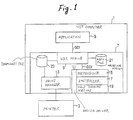
- Fig. 1 shows a configuration of an embodiment of an area discrimination system according to the present invention.
- the reference numeral 1 represents a host computer, and 3 represents an ink jet terminal printer connected to the host computer 1.
- the host computer 1 carries an application program (hereinafter simply referred to as "application”) 5 and an operating system 7.
- MS-Windows by Microsoft Corp. is used as the operating system 7.
- This operating system 7 includes a graphic device interface (hereinafter abbreviated to "GDI") module 9, a printer device driver (hereinafter abbreviated to “device driver”) 11 suitable for the printer 3, and a print manager 13.
- GDI graphic device interface
- device driver printer device driver
- the GDI module 9 supplies the application 5 with a common graphic device interface (GDI) which is prescribed for the convenience of application development and which does not depend on output devices such as a printer, a display, and so on.
- GDI common graphic device interface
- the GDI module 9 also supplies the device driver 11 with a device driver interface (hereinafter abbreviated to "DDI") which is prescribed for the convenience of device drive development.
- DDI device driver interface
- the device driver 11 is designed for exclusive use for its associated device (the printer 3 in this case).
- the GDI module 9 serves as a converter which converts a function call of the GDI written in a device-independent form into a function call of the DDI written in a device-dependent form.
- the device driver 11 converts a drawing function given through the GDI module 9 by the application 5, into an output form which can be recognized by the printer 3.
- the device driver 11 has a rasterizer 17 for making up data for every pixel on the basis of the drawing function, and a half toning portion 19 for converting the multi-tone data for every pixel from the rasterizer 17 into a binary dot pattern for half-tone expression, as illustrated in the drawing.
- the configuration of the device driver 11 varies depending on its associated device. For example, when the device driver 11 makes up a printer output written in a high level page description language such as a postscript, the device driver 11 is provided with a processing portion (not shown) for translating drawing functions into the page description language. When the device driver 11 is associated with a printer such as a thermally subliming printer having a gradation expressing function, the half toning portion 19 is not required.
- the device driver 11 has a preprocessor 15. That is, this preprocessor 15 carries out an area discrimination processing relating to black areas on the basis of the drawing function prior to the conversion processing from the drawing function into the printer output form by means of the rasterizer 17, the half toning portion 19, or the like, so that the original drawing function is rewritten on the basis of the result of the above processing. That is, unlike the conventional case, the preprocessor 15 does not perform area discrimination on a bit map, but it performs area discrimination in the stage of DDI which is a high level language.
- the print manager 13 transfers a printer output file made up by the device driver 11 to the printer 3.
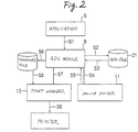
- Fig. 2 shows a total flow of information when printing is performed in the above-mentioned configuration.
- the application 5 supplies the GDI module 9 with a function call (hereinafter referred to as "GDI call”) for a drawing function of GDI (hereinafter referred to as "GDI function”)(Sl).
- GDI call a function call for a drawing function of GDI (hereinafter referred to as "GDI function")(Sl).
- the GDI function for example, there are provided a variety of drawing functions such as a function for drawing a specific figure such as an ellipse, a rectangle or the like, a function for outputting a designated text, a function for making up a bit map, and so on.
- the GDI call has a construction in which some predetermined arguments are added to the designation of these GDI functions.
- the coordinates, size, and so on, of a drawn object (hereinafter referred to as a "primitive") such as a figure, a text, or the like, in a page are specified on the basis of the arguments.
- a GDI function to designate or change the attributes such as the coordinates, size, color, and so on, of the primitive is also provided.
- the GDI module 9 stores these GDI calls in a meta-file 21 (S2).
- This meta-file 21 is made up in a desired storage such as a hard disk, or the like.
- the GDI module 9 calls DDI drawing functions (hereinafter abbreviated to "DDI function” ) corresponding to the drawing functions of the meta-file 21 one by one. That is, function calls of DDI functions (hereinafter abbreviated to "DDI call” ) corresponding to the GDI functions and corresponding to the drawing faculty of a device are sent to the device driver 11 (S3 and S4).
- DDI drawing functions hereinafter abbreviated to "DDI function”
- each DDI call is basically constituted by the designation of a DDI function and some arguments in the same manner as that of each GDI call, and the arguments specify coordinates or size of a primitive in a page. Further, there is provided a DDI function to designate or change attributes such as coordinates, size, color, and so on, of the primitive.
- the device driver 11 converts a called DDI function into an output form (a bit map in this embodiment) which can be recognized by the printer 3, and supplies this printer output to the GDI module 9 (S5).
- the GDI module 9 stores this printer output in a temporary file 23 (S6).
- the GDI module 9 informs the print manager 13 that a new print job is ready (S7).
- the print manager 13 reads the temporary file 23, and transfers the temporary file 23 to the printer 3.
- the print manager 13 deletes the temporary file 23 which has stored the output content (S8, S9).
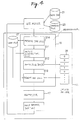
- Fig. 3 shows the operation of the device driver 11 in the above whole operation more specifically.
- the preprocessor 15 receives one page of DDI calls from the GDI module 9, grasps the coordinates, sizes and colors of primitives to be drawn by called drawing functions, and detects intersection points (contact points) between a black primitive and a color primitive (S11).
- the preprocessor 15 makes up a flag table 25 showing the result of the intersection point detection (12).
- the flag table 25 is constituted by flags arranged correspondingly to one page of the DDI calls one by one, and in the flag table 25, only flags corresponding to black primitives having intersection points with color primitives (that is, contacting therewith) are set to "1" while the other flags are set to "0".
- the preprocessor 15 Upon finishing of making up the flag table 25, the preprocessor 15 makes the GDI module 9 send the preprocessor 15 the DDI calls of the meta-file 21 again, and rewrites the DDI calls with reference to the flag table 25 so as to replace the color of the black primitives corresponding to the flags set to "1", which is pure black, by opposite black (S13).
- the content of this function of color replacement is such that, for example, the initial color which is designated as "0,0,0" in 256 gradation color values (printing is made in pure black in this case) is changed into the designation including color components uniformly like "4, 4, 4" (printing is made in composite black in this case).
- the DDI calls are sent to the rasterizer 17 and converted into bit map data.
- This bit map data is sent to the half toning portion 19 and converted into a binary dot pattern for every pixel so as to be changed into a final printer output form.
- This converted printer output is sent to the GDI module 9 and written in the temporary file 23, and thereafter transferred to the printer.
- the black primitives which have not been subjected to color replacement are printed in pure black.
- the black primitives which have been subjected to color replacement are printed in composite black.
- Fig. 4 shows another example of the operation of the aforementioned preprocessor 15.
- DDI calls received from the GDI module 9 are preserved in a work file 27 (S14). Then, either the above-mentioned intersection point detection is performed upon the DDI calls stored in this work file 27 (S11), or rewriting of the DDI calls of color replacement is performed thereon (S13), on both.
- S11 work file 27
- S13 rewriting of the DDI calls of color replacement
- Fig. 5 shows more in detail the intersection point detection and the processing of making up a flag table (S11 and S12) shown in Fig. 3 and 4.
- DDI calls are inputted (S21), and attributes such as coordinates, sizes, colors, and so on, of primitives to be drawn are grasped and stored (S22). These attributes can be grasped on the basis of arguments of the DDI calls or preceding DDI calls having contents of designation or modification of the attributes.
- a flag table 27 where flags corresponding to color primitives are set to "0" and flags corresponding to black primitives are set to "1" is made upon the basis of the grasped colors.
- vectors expressing the outline of a target primitive are obtained from the coordinates and size of the primitive by operations, and stored (S23).
- a first tab of a predetermined width is added to the outer circumference of the outline, and the outline vectors are calculated again so that the stored values of the outline vectors are renewed (S32, S24).
- the width of this first tab is made to correspond to a distance (for example, three dots) necessary and sufficient for dots not to contact with each other.
- the optimum value of this first tab width varies in accordance with set conditions such as the kind of paper, the kind of ink, the resolution, and so on, even in a printer of the same kind, the optimum value is read out from a previously provided table 31 of correspondence between the set conditions and the optimum value of the first tab width.
- intersection point check is performed only upon the preceding black primitives in which no intersection point with any color primitive and first tab has been detected yet (the corresponding flags in the flag table 25 which will be described later are "0"), in the case where the target primitive is color (the corresponding flag in the table 27 is "0").
- This intersection point check is completed in a very short time because it can be performed by the operations of outline vectors.
- a new flag table 25 is made up corresponding to the result of the above intersection point check (S26). That is, in this flag table 25, in the case where a target primitive is black, the flag of the primitive is set to "1" if the target primitive has an intersection point with a color primitive and first tab and first tab, while it is set to "0" if the target primitive has no intersection point with any color primitive and first tab. On the other hand, in the case where the target primitive is color, the flag of the target primitive is set to "0", and the flags of preceding black primitives having intersection points with the target color primitive and first tab are changed from "0" to "1". Consequently, in the flag table 25, the flags of black primitives contacting with color primitives and first tabs are set to "1", and the flags of all the other primitives are set to "0".
- processing is performed so as to detect, of black primitives having no contact with any color primitive and first tab, those which are near black primitives contacting with color primitive and first tab.
- Black primitives having no contact with any color primitives and first tabs are normally printed in pure black as will be described later, and black primitives contacting with color primitives and first tabs are printed in composite black.
- the above-mentioned processing is performed to print also such black primitives having no contact with any color primitive and first tab but close to or contacting a black primitive having such contact in composite black exceptionally.
- a flag in the table 27 corresponding to a target primitive is checked (S27), and if the flag is "1" (that is, black), a second tab width is added to the outer circumference of the outline vectors of the target primitive, and the outline vectors are calculated again and stored (S28).
- the second tab width herein corresponds to the spaced distance (for example, about 2.5 mm (1/10 inch)) between composite black and pure black so that the difference of tone between the composite black and the pure black cannot be recognized by human eyes (for example, the tab width is 1.25 mm (1/20 inch) when the spaced distance is 2.5 mm (1/10 inch)).
- the second tab width is read from a corresponding table 33 prepared in advance.
- intersection points between outline vectors (to which the second tab width has been added) of the target black primitive and the other black primitives are checked (S29).
- the intersection point check is performed only on black primitives contacting with color primitives and first tabs or detected being near such black primitives (the corresponding flags in the flag table 25 are "1").
- the intersection point check is performed only on preceding black primitives the corresponding flags of which in the flag table 25 are "0" contrary to the above case.
- the flag table 25 is rewritten on the basis of the result of this intersection point check (S30). That is, in the case where the target black primitive does not contact with any color primitive and first tab, the flag corresponding to the target black primitive is changed from "0" to "1” if an intersection point is found in the check of the step S29, and rewriting is not performed if no intersection point is located. In the case where the target black primitive contacts with color primitives and first tabs, flags corresponding to the other preceding black primitives having intersection points with the target black primitive and second tab are changed from "0" to "1” if an intersection point is found in the check of the step S29, and rewriting is not performed if no intersection point is located.
- flags of black primitives contacting with color primitives and first tabs or black primitives and second tabs which themselves contact color primitives and first tabs are set to "1", and flags of the other primitives are set to "0".
- the flag "1” herein designates a black primitive to be printed in composite black
- the flag "0” designates a primitive to be printed in original color (pure black in the case of a black primitive) according to a drawing command given by the application.
- intersection point detection processing that is, area discrimination processing
- DDI calls which are written in a high level language
- the quantity of data to be processed is far smaller than that in conventional processing performed on a bit map, and the existence of contact can be found by vector operations immediately, so that the processing is finished in a very short time.
- Fig. 6 shows an example of an image printed in the embodiment which has been described.
- an area 71 is a color primitive.
- Areas 61, 63, 65 and 67 are black primitives printed in composite black.
- the areas 61 and 63 contact with the color primitive of the area 71 (or are disposed within a distance of three dots), and the areas 65 and 67 are disposed within 2.5 mm (1/10 inch) from such black primitives or black primitives which are themselves within 2.5 mm (1/10 inch) from such black primitives (i.e. including the case where they are combined in chain).
- An area 69 is a black primitive printed in pure black, and this does not contact with any color primitive (and is disposed at a distance of four dots or more), and is disposed at a distance of 2.5 mm (1/10 inch) or more from the composite black primitives 61 to 67.
- Such a problem is therefore solved in the present invention in such a manner that means for performing a bit image area color attribute changing processing inquires all the color attributes in the bit image area, and all attributes of pure black are changed to values designating composite black. Consequently, it becomes unnecessary to check the relationship of contact between black areas and color areas thoroughly pixel by pixel along the outline of each of all the areas as in a conventional system, so that the object to obtain a printed picture having no sense of incompatibility with human eyes in a short time can be attained.
- Such means for performing color attribute changing processing in a bit image area may be put in the above-mentioned preprocessor, or be put in another position in the device driver.
- the present invention can be applied to this case without any problem if GDI functions thereof are written in a high level language.
- image area discrimination for deciding which one of composite black and pure black should be used can be performed in a short time in an ink jet printing system.
Abstract
Description
- The present invention relates to printing of black areas in an ink jet color printing system using color ink and black ink, and particularly relates to a system of black area discrimination for appropriately using either composite black formed by a color ink mixture or pure black formed by only black ink.
- Ink of four colors, that is, ink of three colors of cyan, magenta and yellow (hereinafter abbreviated to "C", "M" and "Y" respectively) and ink of pure black are generally used in an ink jet color printing system. Ink with a property to penetrate paper so quickly as to prevent color mixing (hereinafter referred to as "super-penetration ink") is used as color ink in order to realize color printing at a high speed and at a low running cost. On the other hand, ink with a property so as not to penetrate paper much to thereby keep its shape as it is upon reaching the paper (hereinafter referred as "slow-penetration ink") is used as pure black ink because of its usage to print letters or signs with sharp outline shapes.
- As is well known, to print black, there is a method in which pure black ink is used, and a method in which a mixture of ink of three colors of C, M and Y is used. Black in the latter case is called composite black.
- In the case where a black area in an image picture is printed, a printing method is known in which printing is performed with composite black when this black area contacts with a color area, and printing is performed with pure black when the black area does not contact with any color area. This method solves a so-called color mixing problem caused by contact of super-penetration ink (color ink) with slow-penetration ink (pure black ink) on paper. In connection with this printing method, there is also known a method in which pure black is used more in a black area at a predetermined distance or more from any black area printed with composite black, in order to make it hard to recognize a delicate difference of hue between pure black and composite black by human eyes. Further, there is also known a method in which black is printed by mixing mixture dots of C and M and dots of pure black. This mixture black is also called composite black.
- When composite black and pure black are alternatively used as mentioned above, it is necessary to carry out a processing to grasp the positional relationship between respective black areas and color areas in an image to thereby judge which ink should be used in the respective black areas (hereinafter, this processing will be referred to as "area discrimination processing").
- What is disclosed in Japanese Unexamined Patent Publication No. Hei-5-276373 is known as one of the conventional techniques relating to this area discrimination processing. In this known method, for example, in an ordinary system constituted by a host computer and a terminal printer, print data made up by an application in the host computer is first converted into bit map data suitable for the printer, and thereafter the above-mentioned area discrimination processing is performed upon this bit map data.
- It is a problem belonging to this well-known area discrimination method that processing time becomes very long. One of the reasons therefor is that a data quantity of bit map data is too large. For example, megabytes of data are required to define an image of 10 x 10 inches and 300 dpi (dots per inch) by a bit map.
- Another reason why processing time becomes long is that in order to carry out area discrimination on a bit map, the contact relationship between a black area and color area must be checked along an outline of each of all the areas pixel by pixel thoroughly. For example, assume that such a check is started from the left end of a black line which is extended right and left. Then, if this line contacts with a color area only at the right end, or if the line does not contact with any color area, a discrimination result cannot be obtained before the whole area of the line from the left end to the right end has been checked.
- It is therefore an object of the present invention to finish area discrimination as soon as possible in a system in which areas of an image are discriminated to appropriately alternatively use composite black and pure black in an ink jet printing system.
- It is another object of the present invention to obtain, in a short time, a color printed image, where there is no sense of incompatibility to human eyes.
- In order to solve the foregoing problems, in a first aspect, the present invention provides a black area discrimination system for ink jet color printing using a black ink and at least one color ink, characterised by comprising:
- attribute acquisition means supplied with a description in which a series of drawing procedures for drawing a picture to be printed are described in a high level language, for acquiring attributes about positions, sizes and colors of individual areas drawn in accordance with said respective drawing procedures;
- intersection point detection means for detecting black areas including intersection points with color areas on the basis of said acquired attributes of said individual areas; and
- discrimination information generation means for generating information for discriminating said black areas detected by said intersection point detection means from black areas not detected thereby.
- In a second aspect, the present invention provides a black area discriminating method for ink jet color printing using a black ink and at least one color ink characterised by comprising the steps of:
- acquiring an attribute about positions, sizes and colors of areas drawn in accordance with each of said respective drawing procedures, responding to a description in which a series of drawing procedures for drawing a picture to be printed are described in a high level language;
- detecting a black area including an intersection point with a color area on the basis of said acquired attribute of said respective area; and
- generating information for discriminating said black areas detected by said intersection point detection step from other black areas.
- According to the system of the present invention, for example, in an ordinary system constituted by a host computer and a printer, before print data made up by an application in the host computer is converted into final bit map data, the processing of area discrimination is performed on the basis of a description in a high level language in the stage where this print data is expressed in the form of such a description. That is, print data made up by any application has a construction in which a series of drawing procedures for drawing a page to be printed are described by use of a predetermined high level language which is an interface of an operating system. In the system of the present invention, black areas included in the page to be printed are discriminated in the stage of a higher level description than a bit map, such as a description of drawing procedures written in the highest level language made up by the application, a description written in an intermediate level language converted from the description of the drawing procedures by the operating system, or the like.
- Therefore, the quantity of data to be processed is far smaller than that in the conventional case where area discrimination is performed on the basis of a bit map. In addition, since attributes, such as positions, sizes, colors, and so on, of areas of a figure or a text to be drawn are defined as numerical information in such a high level language, contact/noncontact between the areas can be judged immediately through arithmetic operation of the numerical information. As a result, the processing can be finished in a very short time.
- In a preferred embodiment, not only black areas contacting with color areas but also black areas disposed within a predetermined short distance from color areas are discriminated.
- Advantageously black areas containing or disposed within a predetermined short distance from black areas contacting or disposed within a predetermined short distance from color areas are also discriminated. The description written in the high level language is rewritten on the basis of the result of this area discrimination. That is, the description in which a series of drawing procedures are written in the high level language is revised so that black areas contacting with color areas and black areas disposed within a predetermined short distance from the black areas are changed in color from pure black to composite black. The conversion into a bit map is performed on the basis of this revised description. Therefore, the same conventional module used for conversion from a high level language into a bit map can be used also in this case.
- Specific embodiments of the invention will now be described, by way of example only, with reference to the accompanying diagrammatic figures, in which;
- Fig. 1 shows a block diagram illustrating the configuration of an embodiment of an area discrimination system according to the present invention;
- Fig. 2 shows a block diagram for explaining the whole flow of information at the time of printing in the same embodiment;
- Fig. 3 shows a block diagram for explaining tan operation of a device driver in the same embodiment;
- Fig. 4 shows a block diagram for explaining another operation of the device driver in the same embodiment;
- Fig. 5 shows a flow chart showing an intersection point detection processing of a preprocessor in the same embodiment; and
- Fig. 6 shows a diagram illustrating an embodiment of a printed image according to the same embodiment.
- An embodiment of the present invention will be described below in detail with reference to the drawings.
- Fig. 1 shows a configuration of an embodiment of an area discrimination system according to the present invention.
- In Fig. 1, the
reference numeral 1 represents a host computer, and 3 represents an ink jet terminal printer connected to thehost computer 1. Thehost computer 1 carries an application program (hereinafter simply referred to as "application") 5 and anoperating system 7. - In this embodiment, MS-Windows by Microsoft Corp. is used as the
operating system 7. Thisoperating system 7 includes a graphic device interface (hereinafter abbreviated to "GDI")module 9, a printer device driver (hereinafter abbreviated to "device driver") 11 suitable for theprinter 3, and aprint manager 13. - The GDI
module 9 supplies theapplication 5 with a common graphic device interface (GDI) which is prescribed for the convenience of application development and which does not depend on output devices such as a printer, a display, and so on. - The GDI
module 9 also supplies thedevice driver 11 with a device driver interface (hereinafter abbreviated to "DDI") which is prescribed for the convenience of device drive development. In accordance with this DDI, thedevice driver 11 is designed for exclusive use for its associated device (theprinter 3 in this case). The GDImodule 9 serves as a converter which converts a function call of the GDI written in a device-independent form into a function call of the DDI written in a device-dependent form. - The
device driver 11 converts a drawing function given through theGDI module 9 by theapplication 5, into an output form which can be recognized by theprinter 3. For example, when the output form to theprinter 3 is a bit map, thedevice driver 11 has arasterizer 17 for making up data for every pixel on the basis of the drawing function, and ahalf toning portion 19 for converting the multi-tone data for every pixel from therasterizer 17 into a binary dot pattern for half-tone expression, as illustrated in the drawing. - The configuration of the
device driver 11 varies depending on its associated device. For example, when thedevice driver 11 makes up a printer output written in a high level page description language such as a postscript, thedevice driver 11 is provided with a processing portion (not shown) for translating drawing functions into the page description language. When thedevice driver 11 is associated with a printer such as a thermally subliming printer having a gradation expressing function, thehalf toning portion 19 is not required. - In either configuration, one of features of the
device driver 11 is that thedevice driver 11 has apreprocessor 15. That is, thispreprocessor 15 carries out an area discrimination processing relating to black areas on the basis of the drawing function prior to the conversion processing from the drawing function into the printer output form by means of therasterizer 17, thehalf toning portion 19, or the like, so that the original drawing function is rewritten on the basis of the result of the above processing. That is, unlike the conventional case, thepreprocessor 15 does not perform area discrimination on a bit map, but it performs area discrimination in the stage of DDI which is a high level language. - The
print manager 13 transfers a printer output file made up by thedevice driver 11 to theprinter 3. - Fig. 2 shows a total flow of information when printing is performed in the above-mentioned configuration.
- In printing, the
application 5 supplies theGDI module 9 with a function call (hereinafter referred to as "GDI call") for a drawing function of GDI (hereinafter referred to as "GDI function")(Sl). - As for the GDI function, for example, there are provided a variety of drawing functions such as a function for drawing a specific figure such as an ellipse, a rectangle or the like, a function for outputting a designated text, a function for making up a bit map, and so on. The GDI call has a construction in which some predetermined arguments are added to the designation of these GDI functions. The coordinates, size, and so on, of a drawn object (hereinafter referred to as a "primitive") such as a figure, a text, or the like, in a page are specified on the basis of the arguments. In addition, a GDI function to designate or change the attributes such as the coordinates, size, color, and so on, of the primitive is also provided.
- The
GDI module 9 stores these GDI calls in a meta-file 21 (S2). This meta-file 21 is made up in a desired storage such as a hard disk, or the like. - When the
application 5 finishes GDI calls for drawing one page, theGDI module 9 calls DDI drawing functions (hereinafter abbreviated to "DDI function" ) corresponding to the drawing functions of the meta-file 21 one by one. That is, function calls of DDI functions (hereinafter abbreviated to "DDI call" ) corresponding to the GDI functions and corresponding to the drawing faculty of a device are sent to the device driver 11 (S3 and S4). - The construction of each DDI call is basically constituted by the designation of a DDI function and some arguments in the same manner as that of each GDI call, and the arguments specify coordinates or size of a primitive in a page. Further, there is provided a DDI function to designate or change attributes such as coordinates, size, color, and so on, of the primitive.
- The
device driver 11 converts a called DDI function into an output form (a bit map in this embodiment) which can be recognized by theprinter 3, and supplies this printer output to the GDI module 9 (S5). TheGDI module 9 stores this printer output in a temporary file 23 (S6). - When the printer output of the whole page has been written in the
temporary file 23, theGDI module 9 informs theprint manager 13 that a new print job is ready (S7). Theprint manager 13 reads thetemporary file 23, and transfers thetemporary file 23 to theprinter 3. When the output to theprinter 3 is completed, theprint manager 13 deletes thetemporary file 23 which has stored the output content (S8, S9). - Fig. 3 shows the operation of the
device driver 11 in the above whole operation more specifically. As shown in fig. 3, first, thepreprocessor 15 receives one page of DDI calls from theGDI module 9, grasps the coordinates, sizes and colors of primitives to be drawn by called drawing functions, and detects intersection points (contact points) between a black primitive and a color primitive (S11). Thepreprocessor 15 makes up a flag table 25 showing the result of the intersection point detection (12). The flag table 25 is constituted by flags arranged correspondingly to one page of the DDI calls one by one, and in the flag table 25, only flags corresponding to black primitives having intersection points with color primitives (that is, contacting therewith) are set to "1" while the other flags are set to "0". - Upon finishing of making up the flag table 25, the
preprocessor 15 makes theGDI module 9 send thepreprocessor 15 the DDI calls of the meta-file 21 again, and rewrites the DDI calls with reference to the flag table 25 so as to replace the color of the black primitives corresponding to the flags set to "1", which is pure black, by opposite black (S13). The content of this function of color replacement is such that, for example, the initial color which is designated as "0,0,0" in 256 gradation color values (printing is made in pure black in this case) is changed into the designation including color components uniformly like "4, 4, 4" (printing is made in composite black in this case). - After the DDI calls are rewritten by such color replacement, the DDI calls are sent to the
rasterizer 17 and converted into bit map data. This bit map data is sent to thehalf toning portion 19 and converted into a binary dot pattern for every pixel so as to be changed into a final printer output form. This converted printer output is sent to theGDI module 9 and written in thetemporary file 23, and thereafter transferred to the printer. As a result, the black primitives which have not been subjected to color replacement are printed in pure black. The black primitives which have been subjected to color replacement are printed in composite black. - Fig. 4 shows another example of the operation of the
aforementioned preprocessor 15. In the operation shown in Fig. 4, DDI calls received from theGDI module 9 are preserved in a work file 27 (S14). Then, either the above-mentioned intersection point detection is performed upon the DDI calls stored in this work file 27 (S11), or rewriting of the DDI calls of color replacement is performed thereon (S13), on both. Thus, the reception of DDI calls from theGDI module 9 is only required once. - Thus, while DDI calls are sent to the
preprocessor 15 by theGDI module 9 twice in the operation of Fig. 3, in the operation of Figure 4 these DDI calls are sent only once. - Fig. 5 shows more in detail the intersection point detection and the processing of making up a flag table (S11 and S12) shown in Fig. 3 and 4.
- First, DDI calls are inputted (S21), and attributes such as coordinates, sizes, colors, and so on, of primitives to be drawn are grasped and stored (S22). These attributes can be grasped on the basis of arguments of the DDI calls or preceding DDI calls having contents of designation or modification of the attributes. A flag table 27 where flags corresponding to color primitives are set to "0" and flags corresponding to black primitives are set to "1" is made upon the basis of the grasped colors.
- Next, checking is made in the procedures of steps S23 to S26 as to whether black primitives and color primitives contact with each other or not.
- That is, first, vectors expressing the outline of a target primitive are obtained from the coordinates and size of the primitive by operations, and stored (S23). Next, only in the case where the primitive is color, a first tab of a predetermined width is added to the outer circumference of the outline, and the outline vectors are calculated again so that the stored values of the outline vectors are renewed (S32, S24). Taking into consideration the size of dots on paper and a position gap of a head of the
printer 3, the width of this first tab is made to correspond to a distance (for example, three dots) necessary and sufficient for dots not to contact with each other. Since the optimum value of this first tab width varies in accordance with set conditions such as the kind of paper, the kind of ink, the resolution, and so on, even in a printer of the same kind, the optimum value is read out from a previously provided table 31 of correspondence between the set conditions and the optimum value of the first tab width. - Next, on the basis of the outline vectors of the primitive (to which a first tab may have been added), and the outline vectors or primitives formed by preceding DDI calls (to which a first tab may have been added), checking is made from vector operations as to whether the target primitive and possible first tab has an intersection point with (or contacts with) any of the preceding primitives and possible first tabs (S25). Here, the intersection point check is performed only upon the preceding color primitives and tabs (the corresponding flags in the table 27 are "0") in the case where the target primitive is black (the corresponding flag in the table 27 is "1"), and vice versa. Furthermore, the intersection point check is performed only upon the preceding black primitives in which no intersection point with any color primitive and first tab has been detected yet (the corresponding flags in the flag table 25 which will be described later are "0"), in the case where the target primitive is color (the corresponding flag in the table 27 is "0"). This intersection point check is completed in a very short time because it can be performed by the operations of outline vectors.
- Next, a new flag table 25 is made up corresponding to the result of the above intersection point check (S26). That is, in this flag table 25, in the case where a target primitive is black, the flag of the primitive is set to "1" if the target primitive has an intersection point with a color primitive and first tab and first tab, while it is set to "0" if the target primitive has no intersection point with any color primitive and first tab. On the other hand, in the case where the target primitive is color, the flag of the target primitive is set to "0", and the flags of preceding black primitives having intersection points with the target color primitive and first tab are changed from "0" to "1". Consequently, in the flag table 25, the flags of black primitives contacting with color primitives and first tabs are set to "1", and the flags of all the other primitives are set to "0".
- Next, in the procedures of steps S27 to S30, processing is performed so as to detect, of black primitives having no contact with any color primitive and first tab, those which are near black primitives contacting with color primitive and first tab. Black primitives having no contact with any color primitives and first tabs are normally printed in pure black as will be described later, and black primitives contacting with color primitives and first tabs are printed in composite black. However, when the distance between two black primitives, one having no contact and one having contacts, is very small, the difference of tone between pure black and composite black becomes conspicuous. Therefore, the above-mentioned processing is performed to print also such black primitives having no contact with any color primitive and first tab but close to or contacting a black primitive having such contact in composite black exceptionally.
- First, a flag in the table 27 corresponding to a target primitive is checked (S27), and if the flag is "1" (that is, black), a second tab width is added to the outer circumference of the outline vectors of the target primitive, and the outline vectors are calculated again and stored (S28). The second tab width herein corresponds to the spaced distance (for example, about 2.5 mm (1/10 inch)) between composite black and pure black so that the difference of tone between the composite black and the pure black cannot be recognized by human eyes (for example, the tab width is 1.25 mm (1/20 inch) when the spaced distance is 2.5 mm (1/10 inch)). Similarly to the first tab width, the second tab width is read from a corresponding table 33 prepared in advance.
- Next, intersection points between outline vectors (to which the second tab width has been added) of the target black primitive and the other black primitives are checked (S29). In this case, when the target black primitive does not contact with any color primitive and first tab (i.e. the corresponding flag in the flag table 25 is "0"), the intersection point check is performed only on black primitives contacting with color primitives and first tabs or detected being near such black primitives (the corresponding flags in the flag table 25 are "1"). On the other hand, when the target black primitive contacts with color primitives and first tabs (the corresponding flag in the flag table 25 is "1"), the intersection point check is performed only on preceding black primitives the corresponding flags of which in the flag table 25 are "0" contrary to the above case.
- Next, the flag table 25 is rewritten on the basis of the result of this intersection point check (S30). That is, in the case where the target black primitive does not contact with any color primitive and first tab, the flag corresponding to the target black primitive is changed from "0" to "1" if an intersection point is found in the check of the step S29, and rewriting is not performed if no intersection point is located. In the case where the target black primitive contacts with color primitives and first tabs, flags corresponding to the other preceding black primitives having intersection points with the target black primitive and second tab are changed from "0" to "1" if an intersection point is found in the check of the step S29, and rewriting is not performed if no intersection point is located. Consequently, in the flag table 25, flags of black primitives contacting with color primitives and first tabs or black primitives and second tabs which themselves contact color primitives and first tabs are set to "1", and flags of the other primitives are set to "0". The flag "1" herein designates a black primitive to be printed in composite black, and the flag "0" designates a primitive to be printed in original color (pure black in the case of a black primitive) according to a drawing command given by the application.
- The above processing is repeated upon all the DDI calls of the page (S31). Consequently, the flag table 25 which shows whether each primitive should be printed in composite black or original color is completed.
- Since the above intersection point detection processing (that is, area discrimination processing) is performed on DDI calls which are written in a high level language, the quantity of data to be processed is far smaller than that in conventional processing performed on a bit map, and the existence of contact can be found by vector operations immediately, so that the processing is finished in a very short time.
- Fig. 6 shows an example of an image printed in the embodiment which has been described. In Fig. 6, an
area 71 is a color primitive.Areas areas areas area 69 is a black primitive printed in pure black, and this does not contact with any color primitive (and is disposed at a distance of four dots or more), and is disposed at a distance of 2.5 mm (1/10 inch) or more from the compositeblack primitives 61 to 67. - In such a printed image, there is no color mixing problem between super-penetration ink and slow-penetration ink, and the difference of tone between pure black and composite black does become a problem. In this embodiment, discrimination of black areas for printing such an image can be performed at a higher speed than the conventional one.
- There is a case where, for example, a bit image area captured by a scanner, or the like, is included in a series of drawing procedures given by an application. In such a case, the above-mentioned area discrimination method cannot be adopted because the inside of the bit image area is not written in a high level language.
- Such a problem is therefore solved in the present invention in such a manner that means for performing a bit image area color attribute changing processing inquires all the color attributes in the bit image area, and all attributes of pure black are changed to values designating composite black. Consequently, it becomes unnecessary to check the relationship of contact between black areas and color areas thoroughly pixel by pixel along the outline of each of all the areas as in a conventional system, so that the object to obtain a printed picture having no sense of incompatibility with human eyes in a short time can be attained. Such means for performing color attribute changing processing in a bit image area may be put in the above-mentioned preprocessor, or be put in another position in the device driver.
- There is not only a case where ink of three colors, that is, C, M and Y, are mixed so as to be used as composite black but also a case where pure black ink is mixed with ink of two colors, that is, C and M so as to be used as composite black. In the present invention, the method of realizing composite black is not limited.
- Although recently there is a printer having a GDI module itself, the present invention can be applied to this case without any problem if GDI functions thereof are written in a high level language.
- Although one embodiment of the present invention has been described above, the present invention can be applied to various other aspects without departing from the spirit and scope thereof.
- As has been described above, according to the present invention, image area discrimination for deciding which one of composite black and pure black should be used can be performed in a short time in an ink jet printing system.
- In addition, a printed image having no sense of incompatibility with human eyes can be obtained thereby.
- The aforegoing description has been given by way of example only and it will be appreciated by a person skilled in the art that modifications can be made without departing from the scope of the present invention.
Claims (9)
- A black area discrimination system for ink jet color printing using a black ink and at least one color ink, characterised by comprising:attribute acquisition means supplied with a description in which a series of drawing procedures for drawing a picture to be printed are described in a high level language, for acquiring attributes about positions, sizes and colors of individual areas drawn in accordance with said respective drawing procedures;intersection point detection means for detecting black areas including intersection points with color areas on the basis of said acquired attributes of said individual areas; anddiscrimination information generation means for generating information for discriminating said black areas detected by said intersection point detection means from black areas not detected thereby.
- A system as claimed in claim 1; wherein said intersection point detection means detects black areas which are disposed within a predetermined distance from color areas in addition to those black areas which intersect color areas, on the basis of said acquired attributes of said individual areas.
- A system according to claim 1 or claim 2 wherein said black area discrimination system further comprises a neighbor area detection means for detecting other black areas which intersect, or are disposed within a predetermined neighbor distance from, said black areas detected by said intersection point detection means; andwherein said discrimination information generation means generates information for discriminating said black areas detected by either said intersection point detection means or said neighbor area detection means from black areas not detected thereby.
- A system according to any preceding claim, wherein said discrimination information generation means makes correction on said description of said series of drawing procedures so as to set the color of said detected black areas to composite black as said information for discriminating.
- A system according to any preceding claim, wherein said black area discrimination system further comprises a bit image area color attribute changing means for changing data expressing pure black, of color attribute data included in a bit image area, into data expressing composite black, on the basis of said acquired attributes of individual areas.
- A system according to any preceding claim, wherein said black area discrimination system further comprises means for making up bit map data in which said detected black areas are expressed as composite black and said black areas not detected are expressed as pure black, in response to said description of said series of drawing procedures and said discriminating information.
- A black area discriminating method for ink jet color printing using a black ink and at least one color ink, characterised by comprising the steps of:acquiring an attribute about positions, sizes and colors of areas drawn in accordance with each of said respective drawing procedures, responding to a description in which a series of drawing procedures for drawing a picture to be printed are described in a high level language;detecting a black area including an intersection point with a color area on the basis of said acquired attribute of said respective area; andgenerating information for discriminating said black areas detected by said intersection point detection step from other black areas.
- A method according to claim 7, wherein said detecting step includes detecting a black area which is disposed within a predetermined distance from a color area in addition to a black area including an intersection point with a color area, on the basis of said acquired attribute of said respective area.
- A method according to claim 7 or claim 8, wherein said black area discrimination method further comprises a step of detecting other black areas which intersect, or are within a predetermined neighbor distance from, said black area detected by said intersection point detection step; andwherein information for discriminating said black areas detected by either said intersection point detection stop or said neighbor area detection step from black areas not detected thereby is generated in said discrimination information generation step.
Applications Claiming Priority (3)
| Application Number | Priority Date | Filing Date | Title |
|---|---|---|---|
| JP24986594 | 1994-10-14 | ||
| JP249865/94 | 1994-10-14 | ||
| JP24986594A JP3175498B2 (en) | 1994-10-14 | 1994-10-14 | Black area identification method for ink jet color printing |
Publications (3)
| Publication Number | Publication Date |
|---|---|
| EP0707281A2 true EP0707281A2 (en) | 1996-04-17 |
| EP0707281A3 EP0707281A3 (en) | 1997-06-25 |
| EP0707281B1 EP0707281B1 (en) | 2004-03-31 |
Family
ID=17199348
Family Applications (1)
| Application Number | Title | Priority Date | Filing Date |
|---|---|---|---|
| EP95307289A Expired - Lifetime EP0707281B1 (en) | 1994-10-14 | 1995-10-13 | Ink jet colour printing system and method |
Country Status (4)
| Country | Link |
|---|---|
| US (1) | US5699492A (en) |
| EP (1) | EP0707281B1 (en) |
| JP (1) | JP3175498B2 (en) |
| DE (1) | DE69532791T2 (en) |
Cited By (3)
| Publication number | Priority date | Publication date | Assignee | Title |
|---|---|---|---|---|
| EP0836154A1 (en) * | 1996-09-24 | 1998-04-15 | Xerox Corporation | Printing systems |
| EP1653393A1 (en) * | 2004-10-29 | 2006-05-03 | Hewlett-Packard Development Company, L.P. | Method for black pixel designation in document image data |
| EP1907211A1 (en) * | 2005-07-22 | 2008-04-09 | Ricoh Company, Ltd. | Imaging method and inkjet recording apparatus |
Families Citing this family (12)
| Publication number | Priority date | Publication date | Assignee | Title |
|---|---|---|---|---|
| JP3626966B2 (en) * | 1996-03-28 | 2005-03-09 | コニカミノルタビジネステクノロジーズ株式会社 | Image processing device |
| JP3873427B2 (en) * | 1998-01-30 | 2007-01-24 | ブラザー工業株式会社 | Intermediate file processing apparatus in printer control system and recording medium recorded with control program thereof |
| US6260044B1 (en) | 1998-02-04 | 2001-07-10 | Nugenesis Technologies Corporation | Information storage and retrieval system for storing and retrieving the visual form of information from an application in a database |
| WO2000073076A1 (en) * | 1998-04-11 | 2000-12-07 | Copyer Co., Ltd. | Ink-jet recording method and apparatus |
| US6510426B1 (en) | 1998-09-30 | 2003-01-21 | International Business Machines Corporation | Method and apparatus for compacting a metadatas stream in a data processing system |
| US6295538B1 (en) | 1998-12-03 | 2001-09-25 | International Business Machines Corporation | Method and apparatus for creating metadata streams with embedded device information |
| JP3747130B2 (en) * | 1998-12-22 | 2006-02-22 | キヤノン株式会社 | Information processing apparatus, message display method, interface apparatus, and storage medium storing computer-readable program |
| US7082436B1 (en) | 2000-01-05 | 2006-07-25 | Nugenesis Technologies Corporation | Storing and retrieving the visual form of data |
| KR100497387B1 (en) * | 2003-02-20 | 2005-06-23 | 삼성전자주식회사 | Method and apparatus for forming color image |
| US7234791B2 (en) * | 2005-04-26 | 2007-06-26 | Eastman Kodak Company | Reducing ink bleed artifacts |
| US7652795B2 (en) * | 2005-12-06 | 2010-01-26 | Eastman Kodak Company | Reducing ink bleed artifacts |
| US8422082B2 (en) | 2009-07-22 | 2013-04-16 | Eastman Kodak Company | Reducing ink bleed artifacts for RGB images |
Family Cites Families (10)
| Publication number | Priority date | Publication date | Assignee | Title |
|---|---|---|---|---|
| US4682216A (en) * | 1983-03-08 | 1987-07-21 | Canon Kabushiki Kaisha | Color image picture forming process and apparatus which improves the quality of the black portions of the picture |
| US5031034A (en) * | 1988-06-20 | 1991-07-09 | Canon Kabushiki Kaisha | Image forming and processing apparatus with identification of character portions of images |
| US5057852A (en) * | 1989-12-18 | 1991-10-15 | Eastman Kodak Company | Printhead for color printer providing image edge enhancement |
| US5353388A (en) * | 1991-10-17 | 1994-10-04 | Ricoh Company, Ltd. | System and method for document processing |
| US5168552A (en) * | 1991-10-29 | 1992-12-01 | Hewlett-Packard Company | Color separation in ink jet color graphics printing |
| US5475800A (en) * | 1991-10-29 | 1995-12-12 | Hewlett-Packard Company | Color separation in color graphics printing with limited memory |
| JPH05330086A (en) * | 1992-06-01 | 1993-12-14 | Fuji Xerox Co Ltd | Color image recording device |
| JP3244790B2 (en) * | 1992-07-31 | 2002-01-07 | キヤノン株式会社 | Color inkjet recording method and apparatus |
| US5428377A (en) * | 1992-08-11 | 1995-06-27 | Xerox Corporation | Color spatial filtering for thermal ink jet printers |
| US5579453A (en) * | 1994-12-16 | 1996-11-26 | Xerox Corporation | Smart direct memory access controller |
-
1994
- 1994-10-14 JP JP24986594A patent/JP3175498B2/en not_active Expired - Fee Related
-
1995
- 1995-10-13 DE DE69532791T patent/DE69532791T2/en not_active Expired - Lifetime
- 1995-10-13 EP EP95307289A patent/EP0707281B1/en not_active Expired - Lifetime
- 1995-10-13 US US08/542,930 patent/US5699492A/en not_active Expired - Lifetime
Non-Patent Citations (1)
| Title |
|---|
| None |
Cited By (6)
| Publication number | Priority date | Publication date | Assignee | Title |
|---|---|---|---|---|
| EP0836154A1 (en) * | 1996-09-24 | 1998-04-15 | Xerox Corporation | Printing systems |
| EP1653393A1 (en) * | 2004-10-29 | 2006-05-03 | Hewlett-Packard Development Company, L.P. | Method for black pixel designation in document image data |
| US7246880B2 (en) | 2004-10-29 | 2007-07-24 | Hewlett-Packard Development Company, L.P. | Method for black pixel designation in document image data |
| EP1907211A1 (en) * | 2005-07-22 | 2008-04-09 | Ricoh Company, Ltd. | Imaging method and inkjet recording apparatus |
| EP1907211A4 (en) * | 2005-07-22 | 2009-01-07 | Ricoh Kk | Imaging method and inkjet recording apparatus |
| US8011756B2 (en) | 2005-07-22 | 2011-09-06 | Ricoh Company, Ltd. | Imaging method and inkjet recording apparatus |
Also Published As
| Publication number | Publication date |
|---|---|
| US5699492A (en) | 1997-12-16 |
| EP0707281A3 (en) | 1997-06-25 |
| DE69532791D1 (en) | 2004-05-06 |
| JPH08112917A (en) | 1996-05-07 |
| EP0707281B1 (en) | 2004-03-31 |
| JP3175498B2 (en) | 2001-06-11 |
| DE69532791T2 (en) | 2004-09-30 |
Similar Documents
| Publication | Publication Date | Title |
|---|---|---|
| EP0654759B1 (en) | Printing apparatus | |
| US7692813B2 (en) | Image processing apparatus and method, and storage medium | |
| US5699492A (en) | Black area discrimination system for ink jet color printing and method therefor | |
| US6323958B1 (en) | Printing apparatus | |
| EP1467556B1 (en) | Method, apparatus and program for image processing capable of producing high-quality achromatic images | |
| US6049394A (en) | Color print system, color printer, and a computer readable-recording medium with a computer-executive program stored therein | |
| US6429950B1 (en) | Method and apparatus for applying object characterization pixel tags to image data in a digital imaging device | |
| KR100549492B1 (en) | Apparatus and method for recording document described in markup language | |
| US5784172A (en) | Automatic algorithmic determination of process black over a color field | |
| EP0782098B1 (en) | Method and system for digital color printing | |
| US6348977B1 (en) | Color-controlled conversion of color data | |
| US5930385A (en) | Apparatus and method for image conversion | |
| JPH07222017A (en) | Mapping method | |
| JP3860845B2 (en) | Color image printing system | |
| JP4356953B2 (en) | Image processing system, image processing apparatus, control method therefor, and storage medium | |
| EP1219107B1 (en) | System and method for producing halftoned color separations for an output imaging device | |
| JP3636891B2 (en) | Color image output method | |
| JPH1051652A (en) | Information processing unit and method | |
| JP3158101B2 (en) | Color image processing apparatus and color image processing method | |
| JP3533657B2 (en) | Printing system, printer, printer driver, and program recording medium | |
| JP2000261670A (en) | Image processing unit, its method and memory computer- readable | |
| JP2000141810A (en) | Imaging apparatus, imaging method, and computer readable memory | |
| JPH10157240A (en) | Printing method, printing apparatus, and recording medium | |
| KR20030013622A (en) | Printer controlling system having the changing function of color-tone and method thereof | |
| JPH07137351A (en) | Document processor |
Legal Events
| Date | Code | Title | Description |
|---|---|---|---|
| PUAI | Public reference made under article 153(3) epc to a published international application that has entered the european phase |
Free format text: ORIGINAL CODE: 0009012 |
|
| AK | Designated contracting states |
Kind code of ref document: A2 Designated state(s): DE FR GB |
|
| PUAL | Search report despatched |
Free format text: ORIGINAL CODE: 0009013 |
|
| AK | Designated contracting states |
Kind code of ref document: A3 Designated state(s): DE FR GB |
|
| 17P | Request for examination filed |
Effective date: 19971215 |
|
| 17Q | First examination report despatched |
Effective date: 20001004 |
|
| GRAP | Despatch of communication of intention to grant a patent |
Free format text: ORIGINAL CODE: EPIDOSNIGR1 |
|
| GRAS | Grant fee paid |
Free format text: ORIGINAL CODE: EPIDOSNIGR3 |
|
| GRAA | (expected) grant |
Free format text: ORIGINAL CODE: 0009210 |
|
| AK | Designated contracting states |
Kind code of ref document: B1 Designated state(s): DE FR GB |
|
| RAP1 | Party data changed (applicant data changed or rights of an application transferred) |
Owner name: SEIKO EPSON CORPORATION |
|
| REG | Reference to a national code |
Ref country code: GB Ref legal event code: FG4D |
|
| REF | Corresponds to: |
Ref document number: 69532791 Country of ref document: DE Date of ref document: 20040506 Kind code of ref document: P |
|
| ET | Fr: translation filed | ||
| PLBE | No opposition filed within time limit |
Free format text: ORIGINAL CODE: 0009261 |
|
| STAA | Information on the status of an ep patent application or granted ep patent |
Free format text: STATUS: NO OPPOSITION FILED WITHIN TIME LIMIT |
|
| 26N | No opposition filed |
Effective date: 20050104 |
|
| PGFP | Annual fee paid to national office [announced via postgrant information from national office to epo] |
Ref country code: DE Payment date: 20101006 Year of fee payment: 16 |
|
| PGFP | Annual fee paid to national office [announced via postgrant information from national office to epo] |
Ref country code: GB Payment date: 20101013 Year of fee payment: 16 |
|
| PGFP | Annual fee paid to national office [announced via postgrant information from national office to epo] |
Ref country code: FR Payment date: 20111103 Year of fee payment: 17 |
|
| GBPC | Gb: european patent ceased through non-payment of renewal fee |
Effective date: 20121013 |
|
| REG | Reference to a national code |
Ref country code: FR Ref legal event code: ST Effective date: 20130628 |
|
| PG25 | Lapsed in a contracting state [announced via postgrant information from national office to epo] |
Ref country code: GB Free format text: LAPSE BECAUSE OF NON-PAYMENT OF DUE FEES Effective date: 20121013 Ref country code: DE Free format text: LAPSE BECAUSE OF NON-PAYMENT OF DUE FEES Effective date: 20130501 |
|
| REG | Reference to a national code |
Ref country code: DE Ref legal event code: R119 Ref document number: 69532791 Country of ref document: DE Effective date: 20130501 |
|
| PG25 | Lapsed in a contracting state [announced via postgrant information from national office to epo] |
Ref country code: FR Free format text: LAPSE BECAUSE OF NON-PAYMENT OF DUE FEES Effective date: 20121031 |