EP0705186B1 - Device for controlling a windscreen-washer installation - Google Patents
Device for controlling a windscreen-washer installation Download PDFInfo
- Publication number
- EP0705186B1 EP0705186B1 EP94918290A EP94918290A EP0705186B1 EP 0705186 B1 EP0705186 B1 EP 0705186B1 EP 94918290 A EP94918290 A EP 94918290A EP 94918290 A EP94918290 A EP 94918290A EP 0705186 B1 EP0705186 B1 EP 0705186B1
- Authority
- EP
- European Patent Office
- Prior art keywords
- signals
- value
- wiper
- sensor device
- signal
- Prior art date
- Legal status (The legal status is an assumption and is not a legal conclusion. Google has not performed a legal analysis and makes no representation as to the accuracy of the status listed.)
- Expired - Lifetime
Links
Images


Classifications
-
- G—PHYSICS
- G01—MEASURING; TESTING
- G01V—GEOPHYSICS; GRAVITATIONAL MEASUREMENTS; DETECTING MASSES OR OBJECTS; TAGS
- G01V8/00—Prospecting or detecting by optical means
- G01V8/10—Detecting, e.g. by using light barriers
- G01V8/20—Detecting, e.g. by using light barriers using multiple transmitters or receivers
-
- B—PERFORMING OPERATIONS; TRANSPORTING
- B60—VEHICLES IN GENERAL
- B60S—SERVICING, CLEANING, REPAIRING, SUPPORTING, LIFTING, OR MANOEUVRING OF VEHICLES, NOT OTHERWISE PROVIDED FOR
- B60S1/00—Cleaning of vehicles
- B60S1/02—Cleaning windscreens, windows or optical devices
- B60S1/04—Wipers or the like, e.g. scrapers
- B60S1/06—Wipers or the like, e.g. scrapers characterised by the drive
- B60S1/08—Wipers or the like, e.g. scrapers characterised by the drive electrically driven
- B60S1/0818—Wipers or the like, e.g. scrapers characterised by the drive electrically driven including control systems responsive to external conditions, e.g. by detection of moisture, dirt or the like
-
- G—PHYSICS
- G01—MEASURING; TESTING
- G01N—INVESTIGATING OR ANALYSING MATERIALS BY DETERMINING THEIR CHEMICAL OR PHYSICAL PROPERTIES
- G01N21/00—Investigating or analysing materials by the use of optical means, i.e. using sub-millimetre waves, infrared, visible or ultraviolet light
- G01N21/17—Systems in which incident light is modified in accordance with the properties of the material investigated
- G01N21/41—Refractivity; Phase-affecting properties, e.g. optical path length
- G01N21/43—Refractivity; Phase-affecting properties, e.g. optical path length by measuring critical angle
-
- G—PHYSICS
- G01—MEASURING; TESTING
- G01N—INVESTIGATING OR ANALYSING MATERIALS BY DETERMINING THEIR CHEMICAL OR PHYSICAL PROPERTIES
- G01N21/00—Investigating or analysing materials by the use of optical means, i.e. using sub-millimetre waves, infrared, visible or ultraviolet light
- G01N21/17—Systems in which incident light is modified in accordance with the properties of the material investigated
- G01N21/55—Specular reflectivity
-
- G—PHYSICS
- G01—MEASURING; TESTING
- G01N—INVESTIGATING OR ANALYSING MATERIALS BY DETERMINING THEIR CHEMICAL OR PHYSICAL PROPERTIES
- G01N21/00—Investigating or analysing materials by the use of optical means, i.e. using sub-millimetre waves, infrared, visible or ultraviolet light
- G01N21/84—Systems specially adapted for particular applications
- G01N21/8422—Investigating thin films, e.g. matrix isolation method
-
- G—PHYSICS
- G01—MEASURING; TESTING
- G01N—INVESTIGATING OR ANALYSING MATERIALS BY DETERMINING THEIR CHEMICAL OR PHYSICAL PROPERTIES
- G01N21/00—Investigating or analysing materials by the use of optical means, i.e. using sub-millimetre waves, infrared, visible or ultraviolet light
- G01N21/17—Systems in which incident light is modified in accordance with the properties of the material investigated
- G01N21/55—Specular reflectivity
- G01N2021/551—Retroreflectance
Definitions
- the invention relates to a device for controlling a windshield wiper system according to the preamble of claim 1.
- Such a device is known from DE-A 41 41 348.
- attempts are made to make the signals determined by an optoelectronic sensor device accessible to the control of a windshield wiper system. Since a wiper device is required for reliable cleaning of the windshield, signals which distort the control signals for the windshield wiper motor occur as a result of the wiper sweeping over the sensor device.
- To influence the Drive motor only the signals are used that are generated by the sensor device shortly after the last wiping process until a new wiping cycle is initiated, that is, not during the wiping.
- Wetting gradually reduces the signal that is constantly present until a reference value corresponding to the condition of the window is undershot, which leads to the triggering of the wiper.
- the reference value is continuously recalculated in order to filter out the signals caused by wetting from the high interference level. The size of individual drops cannot be determined.
- a device in which a light barrier is used as the sensor device.
- This light barrier is not influenced by wiping over by the wiper, so that no signals are emitted by the wiper itself.
- the signals occurring are assessed qualitatively to determine whether they occur during the actual wiping process, that is to say during the movement of the wiper, or at a point in time when the wiper is in the idle state.
- the signals summed up during the actual wiping process are then multiplied by a factor 1, which takes the wiping process into account. If the signals added up according to their pulse width reach a threshold value, a wiping process is initiated and the added value is reset to an initial value.
- a programmable interval switch in which the driver actuates the interval switch depending on his visual impairment caused by the wetting. The time between two operations is measured, which is subsequently used as the interval time.
- the present invention seeks to provide a simple and inexpensive arrangement for utilizing the signals determined for controlling a windshield wiper system.
- DE-GM 93 09 837 describes an optoelectronic sensor device in which a plurality of measuring sections are acted on in a clocked manner and the clocked signals determined in this way are corrected via a downstream evaluation device as a function of a time constant.
- This makes it possible, on the one hand, to eliminate external influences, such as extraneous radiation superimposed on the radiation of the arrangement, so that only signals dependent on the wetting result.
- the interference level no longer plays a role in the input signals, each coating and wetting can clearly be assigned to the signals, analogous to the drop size and quantity. As a result, the signal itself can be used to control the windshield wiper analogously to the wetting.
- the incoming signals can be evaluated over the entire period. It is not necessary to evaluate the incoming input signals according to the amplitude; it is only sufficient to count the number of signals or the incoming drops.
- the wiping which also generates signals, is taken into account very simply by the fact that signals for controlling the windshield wiper motor are only given when the number of signals is greater than the signals from the sensor device which are surely caused by sweeping.
- the counting arrangement counts each pulse, so that signals that are to be assigned to wetting with certainty trigger a wiping process.
- a device for controlling a windshield wiper system has a drive motor M which guides at least one wiper, usually two wipers 11, over a wiping area 10a of a windshield.
- a sensor device 12 as is known from DE-GM 93 09 837, is arranged in the wiping area 10a.
- DE-GM 93 09 837 is arranged in the wiping area 10a.
- the sensor device 12 is swept by the wiper 11 at least once during a wiping operation with an edge arrangement and, if it is arranged at any point in the wiping area of the wiper, twice.
- the sensor device is influenced by a coating or a wetting of the disk so that each influencing generates a signal Es analogous to the drop size or amount.
- a signal processing device 13 is coupled to the drive motor M and the sensor device 12 and converts the signals generated by the sensor device 12 into control signals S for the drive motor M.
- the device can also be a switch contact device, which can optionally be assigned to at least one specific position of the wiper during the wiping process. Usually acts it is in the switching contact device 14 to the motor limit switch of the drive motor M, when the wiper 11 is actuated in its parking position.
- the counter Z of a counter arrangement 15 is provided as a means of recognizing the signals generated by the sensor device 12 during the sweep by the wiper 11.
- the counter counts all the signals determined by the sensor device 12 during a wiping process and compares them with a preset specific value. Exceeding this value triggers a wiping process. However, the determined preset value is greater than the number of signals generated by the sensor device 12 during the sweep of the wiper. After triggering the following wiping process, but at the latest after at least one wiping cycle, the value of the counter arrangement 15 is reset to an initial value.
- a switch contact device 14 can also give a signal as soon as the wiper e.g. is in its park position.
- the sensor device itself works optoelectronically, at least two measuring sections being formed by an interaction of radiation transmitters and radiation receivers, which are alternately controlled by a clock generator.
- An evaluation device 16 detects the clocked signals, the signals occurring being compensated to 0 via a time constant, as described in DE-GM 93 09 837. This makes it possible to block out even strong extraneous radiation in such a way that signals are produced which only depend on the coating and the wetting of the pane 10.
- the ability of the sensor device 12 to generate signals analogous to the drop size and quantity is advantageous, regardless of the mode of operation of the sensor (optical, capacitive, etc.).
- a setting arrangement adjusts the radiation power of the individual radiation sources in such a way that, when the sensor-active area is not wetted, each measuring section generates a section of the detection signal whose average amplitude value is equal to the average amplitude value of the sections of the detection signal assigned to the other measuring sections, and a filter circuit for the clocked detection signal filters the difference between the sections assigned to the individual measuring sections for generating a control signal.
- each measuring section generates a section of the detection signal whose average amplitude value is equal to the average amplitude value of the sections of the detection signal assigned to the other measuring sections
- a filter circuit for the clocked detection signal filters the difference between the sections assigned to the individual measuring sections for generating a control signal.
- the switch arrangement for controlling the two radiation sources 2.1 and 2.2 is a clock generator 30 which alternately generates a current pulse at a non-inverting output 30.0 and at an inverting output 30.1 to excite the radiation of the radiation source connected to the output generated the duration of the current pulse.
- One output of the current pulse generator 30 contains a current control element 32 for setting the current value, which can be adjusted by a control signal Sr at its control input 47.
- the retroreflection of these two radiation sources at the coupling location of the radiation receiver 16 is converted by the latter into an electrical output signal S 16, which corresponds to the arrangement shown in FIG. 3 via an amplifier 35 and a high or bandpass filter 36 as a detection signal SD at the output of the filter circuit 36 reached.
- a signal centering stage 48 is connected to the output of the filter circuit 36 and impresses the changes in the detection signal SD on the output of the filter circuit 36 with a center voltage Uz.
- the signal centering stage 48 contains a synchronous demodulator 49 with two demodulator outputs 49.1 and 49.2, which are each assigned to a radiation source. The assignment takes place via a control clock S 30.0 of the current pulse generator 30, which also controls the radiation of the radiation sources.
- the Demodulator outputs 49.1 and 49.2 are connected in the illustrated embodiment to demodulation value memories 50.1 and 50.2, which currently store the mean amplitude value of the signal sections of the demodulation signal SD, which are sampled by the synchronous demodulator 49 and are assigned to the two radiation sources, and in this way form an envelope demodulator.
- the difference value is formed from the instantaneous mean amplitude values of the two detection value memories in a subsequent operational amplifier 51 and a center value is impressed.
- This smoothed detection signal SD m formed in this way which is substantially free of interference with respect to the detection signal SD at the output of the filter circuit 36, is fed to both an evaluation arrangement 41 and a control circuit 52 with a high control time constant Tv.
- the control circuit contains a time constant element 53 and a comparator 54, which generates a control signal Sr for the control input 47 of the current control element 32 from the comparison with a reference signal Sref such that the radiation power of the radiation source 2.1 regulated by the current control element is changed such that the difference in the detection amplitude values at the output of the signal centering stage 48 goes to zero.
- the regulating speed, ie the regulating time constant Tv of the regulating circuit 52 is dimensioned in such a way that it is significantly greater than the slowest changes in a wetting process that are still to be detected.
- the evaluation arrangement 41 can also be connected directly to the output of the two detection value memories 50.1 and 50.2, in particular if the wetting is to be measured by means of the evaluation arrangement.
- the control time constant is significantly greater than an oscillation period of the switching sequence signal that the radiation receiver assigned radiation sources or groups of radiation sources switches.
- the values determined by the counter Z can then be fed directly to a digital-to-analog converter 19, which uses them to form control signals S for the drive motor M.
- a digital-to-analog converter 19 uses them to form control signals S for the drive motor M.
- All signals can be easily evaluated during a wiping process.
- the automatic reset either time-dependent, control voltage-dependent or depending on the wiper position, also reliably detects individually occurring signals.
- the integer distance between the initial value A and the value, when the wiping process is triggered, is increased compared to the value that corresponds to the number of sweeps, e.g. corresponds to the number 1 or 2.
- the first signal can then e.g.
- Setting means 18 can be provided for regulating the response behavior of the sensor device 12. These setting means 18 can also be arranged directly on the sensor device reduce the response behavior of the sensor device as a function of the motor signal Ms of the switch contact device 14 after a predetermined time t v after the start of a wiping process. This leads to a shift in the value from which the existing signals are detected. In this way, control profiles can be formed within the individually pending signals, which already change the signals corresponding to the drops for evaluation purposes. The detection threshold is shifted within usable signals. This results in large drops resulting in an input signal due to the level and / or duration of the signal, with smaller responses, while smaller droplets have no effect.
- signals with a different division ratio can be acquired.
- the setting means 18 for regulating the response behavior of the device the response behavior after a predetermined time t v , which may also be zero and after which the wiper 11 has left its parking position or after which the control signal has been transmitted to the wiper is to regulate from an initial state with a sensitive response to a predetermined intermediate state with an insensitive response and then regulate back to a final state within a specific time t 2 , which preferably corresponds to the initial state.
- a signal from the limit switch may also be dispensed with.
- the signals determined are regulated in the sensor via the control time constant in such a way that the difference value of the signal goes to zero, with a long control time constant the difference value going more slowly to zero than with a short control time constant.
- the setting means 18 regulate the regulating time constant shorter than during a wiping process a time during which there is no wetting. This alone makes it possible to mask out changes in the measurement signals that occur due to self-drying streaks after wiping.
- the control time constant is regulated by the signal processing device 13 as a function of the signal from the motor limit switch E and for a period of approximately 10-30 seconds. The sensitivity is shifted so that only large drops are recognized after the readjustment. As a side effect, a signal generated by the sensor device 12 being swept by the wiper 11 can be evaluated because a large wiping pulse is also generated when there is a lot of rain.
- actuating means 30 can also be provided which, depending on a signal from the switch contact device 14, reduce a division ratio within a predetermined time t 2 to 1: 1, so that initially a plurality of signals Es lead to a single signal until the actuating means 30 Have set the divisor to 1.
- actuating means 30 can also be provided which, depending on a signal from the switch contact device 14, reduce a division ratio within a predetermined time t 2 to 1: 1, so that initially a plurality of signals Es lead to a single signal until the actuating means 30 Have set the divisor to 1.
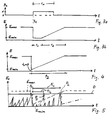
- Fig. 2a first shows the motor signal Ms, which changes over time. As soon as the windshield wiper motor is switched on at time t 1 , a motor signal Ms results which is present over the wiping period t w . The occurrence of this motor signal ensures that the value of the counter Z is set to the initial value A, which is minus 2 according to FIG. 2c. The number minus 2 is selected when the wiper 11 sweeps twice over the sensor device 12 in the wiping area 10a. In FIG. 2b, signals that have occurred over time are also recorded. The first two signals 20 and 21 are caused by the wiper sweeping over the sensor device.
- Each signal leads to a pulse as Input signal Es into the signal processing device 13.
- the counting arrangement 15 counts up to the value 0, which corresponds to the preset specific value, solely by means of these two signals.
- the two further occurring signals 22 then increase this value further, so that depending on the value of the counter Z the digital-to-analog converter 19 now generates control signals S for the drive motor, which in turn lead to the wiper being switched on, which resets the counter to the initial value minus 2.
- This counting arrangement 15 can be used together with a sensitivity control, as can be seen in FIGS. 3a to 5 results.
- the examples show a control of the sensitivity, i.e. a reduction in the amplitude.
- changing the control time constant or the divider ratio has a similar effect.
- 3a shows the motor signal which, at time t 1, regulates the sensitivity E according to FIG. 3b from a maximum value E max to a minimum value E min via the setting means 18 for regulating the response behavior.
- this minimum value is initially maintained over a predetermined time t v .
- the sensitivity E is gradually converted back to the value E max .
- the sensitivity that is to say the response behavior of the entire sensor device, is changed in a controlled manner according to the dashed line. Signals lead to a reaction of the control as soon as the detection threshold is exceeded, whereby several signals can also be stored in a memory in order to achieve a smooth, even wiping process.
- a rain sets in on the left side of FIG. 5, which triggers a wiping at the peak P1, since the detection threshold is exceeded.
- the vehicle user would also have operated his wiper now because of the visual impairment.
- t v 0, the sensitivity at the beginning of the wiping process, that is to say at time t 1 , is reduced from the initial state to an intermediate state.
- the following drops appear smaller in amplitude. If it is heavy rain, they would still reach detection threshold D again immediately.
- the sensitivity gradually increases again and would reach a final state of maximum sensitivity E max which corresponds to the initial state if a drop as peak P2 did not exceed the detection threshold.
- E max maximum sensitivity
- the sensitivity immediately falls to the intermediate state of minimal sensitivity E min .
- the control registers the time between the peaks or between the reduction in sensitivity as the next wiping interval with the interval time ti 1 .
- the changing conditions during a rain would be taken into account by the fact that if the second peak had already reached the detection threshold earlier, for example the peak P 3 shown in broken lines, the interval time ti 2 would have resulted.
- the counting arrangement 15 can be a first memory unit which, when a predetermined value V is exceeded and / or after a predetermined number of wiping processes, which may occur within a certain time, may transmit further signals Sw to a background memory 25, the content of which also generates control signals possibly also influenced after unloading the storage unit.
- the schematic workflow of such a device results from FIG. 9.
- the counting arrangement is started as a storage unit by START.
- the input signals are read in and result in the integer number n.
- the output value A which, for example, reflects the signals caused by the sweep
- the actual number X of signals received during a wiping process results. If this value X is less than 0, this can in principle lead to the end of the wiping or not to the start of the drive motor at all.
- X is greater than 0, depending on the number of signals occurring in the short term, possibly during a wiping process, either the interval switching of the windshield wiper is triggered with a time interval dependent on the number of signals, or, for a large number of signals, e.g. over 13 is immediately, e.g. permanent wiping triggered when a truck drives past.
- a check is carried out to determine whether the value X is greater than a predefined threshold value V, wherein the number of immediately successive wiping operations can also be used here in addition or alternatively. If the value V is exceeded or reached, the value of the background memory 25 is increased, a value which is preferably chosen to be smaller than the total content of the memory in order to achieve a flexible behavior of this background memory. E.g. the value can be increased by 2. In a subsequent step, this value is then e.g. reduced by 1 as soon as a signal is given by the switch contact device.
- This background memory 25 enables the wiping movements to be tracked gradually, since rain does not suddenly begin and stop in nature, so that a regular wiping after rain is achieved.
- the storage unit operating in the foreground here the counting arrangement, can react in a flash to splash water.
- the control unit learns that a corresponding wetting is present which makes a further wiping process necessary. However, if this value is reached before the previous wiping process has ended, the wetting is such that the wiper must remain in continuous operation. In this respect, this premature re-reaching of the value leads to e.g. Extension of the control signal (S) that the drive motor (M) remains in continuous operation. For this, e.g. the time during which the control voltage is applied can be influenced accordingly.
Abstract
Description
Die Erfindung betrifft eine Einrichtung zur Steuerung einer Scheibenwischanlage nach dem Oberbegriff des Anspruches 1.The invention relates to a device for controlling a windshield wiper system according to the preamble of
Eine derartige Einrichtung ist aus der DE-A 41 41 348 bekannt. Bereits dort versucht man, die infolge einer optoelektronischen Sensorvorrichtung ermittelten Signale der Steuerung einer Scheibenwischanlage zugänglich zu machen. Da für eine zuverlässige Reinigung der Scheibe eine Wischvorrichtung erforderlich ist, kommt es infolge des Überstreichens der Sensorvorrichtung durch den Scheibenwischer zu Signalen, die die Steuersignale für den Scheibenwischermotor verfälschen. Zur Beeinflussung des Antriebsmotors werden nur die Signale verwendet, die kurz nach dem letzten Überwischvorgang bis zum Einleiten eines neuen Wischzyklus, also nicht während des Überwischens, von der Sensorvorrichtung erzeugt werden. Eine Benetzung verringert allmählich das ständig anstehende Signal, bis ein dem Zustand der Scheibe entsprechender Referenzwert unterschritten wird, was zum Auslösen des Wischers führt. Der Referenzwert wird ständig neu ermittelt, um die durch eine Benetzung hervorgerufenen Signale aus dem hohem Störpegel herauszufiltern. Einzelne Tropfen können größenmäßig nicht erfaßt werden.Such a device is known from DE-A 41 41 348. Already there, attempts are made to make the signals determined by an optoelectronic sensor device accessible to the control of a windshield wiper system. Since a wiper device is required for reliable cleaning of the windshield, signals which distort the control signals for the windshield wiper motor occur as a result of the wiper sweeping over the sensor device. To influence the Drive motor only the signals are used that are generated by the sensor device shortly after the last wiping process until a new wiping cycle is initiated, that is, not during the wiping. Wetting gradually reduces the signal that is constantly present until a reference value corresponding to the condition of the window is undershot, which leads to the triggering of the wiper. The reference value is continuously recalculated in order to filter out the signals caused by wetting from the high interference level. The size of individual drops cannot be determined.
Aus der DE-A 39 41 905 ist eine Vorrichtung bekannt, bei der als Sensorvorrichtung eine Lichtschranke eingesetzt wird. Diese Lichtschranke wird von einem Überwischen durch den Wischer nicht beeinflußt, so daß allein vom Wischer selbst keine Signale ausgehen. Die auftretenden Signale werden qualitativ dahingehend beurteilt, ob sie während des eigentlichen Wischvorgangs, also während der Bewegung des Wischers auftreten, oder zu einem Zeitpunkt auftreten, zu dem sich der Wischer im Ruhezustand befindet. Um ein zu spätes oder zu frühes Reagieren des Wischers zu vermeiden, werden dann die während des eigentlichen Wischvorgangs aufsummierten Signale mit einem Faktor 1 multipliziert, der dem Wischvorgang Rechnung trägt. Erreichen die nach ihrer Impulsbreite aufsummierten Signale einen Schwellwert, so wird ein Wischvorgang eingeleitet und der aufsummierte Wert auf einen Ausgangswert rückgestellt. Wenngleich das Problem von Signalen, die durch ein Überwischen des Wischers selbst hervorgerufen werden, hier nicht auftritt, so hat diese Vorrichtung doch den Nachteil, daß Regentropfen nicht größenmäßig erfaßt werden können und die Lichtschranke gegen Verschmutzung anfälliger ist, da ihr 'Sichtkreis' nicht vom Wischer mitgereinigt wird.From DE-A 39 41 905 a device is known in which a light barrier is used as the sensor device. This light barrier is not influenced by wiping over by the wiper, so that no signals are emitted by the wiper itself. The signals occurring are assessed qualitatively to determine whether they occur during the actual wiping process, that is to say during the movement of the wiper, or at a point in time when the wiper is in the idle state. In order to avoid the wiper reacting too late or too early, the signals summed up during the actual wiping process are then multiplied by a
Darüberhinaus ist ein programmierbarer Intervallschalter bekannt, bei dem der Fahrer in Abhängigkeit seiner durch die Benetzung hervorgerufenenen Sichtbehinderung den Intervallschalter betätigt. Gemessen wird die Zeit zwischen zwei Betätigungen, die in der Folge als Intervallzeit herangezogen wird.In addition, a programmable interval switch is known in which the driver actuates the interval switch depending on his visual impairment caused by the wetting. The time between two operations is measured, which is subsequently used as the interval time.
Ausgehend von diesem Stand der Technik liegt der vorliegenden Erfindung die Aufgabe zugrunde, eine einfache und kostengünstige Anordnung zur Verwertung der ermittelten Signale zur Steuerung einer Scheibenwischanlage zu schaffen.Based on this prior art, the present invention seeks to provide a simple and inexpensive arrangement for utilizing the signals determined for controlling a windshield wiper system.
Diese Aufgabe wird eine Einrichtung mit den Merkmalen des Anspruches 1 gelöst.This object is achieved by a device having the features of
In DE-GM 93 09 837 wird eine optoelektronische Sensorvorrichtung beschrieben, bei der mehrere Meßstrecken getaktet beaufschlagt werden und die dabei ermittelten getakteten Signale über eine nachgeschaltete Auswertevorrichtung in Abhängigkeit einer Zeitkonstante ausgeregelt werden. Dadurch ist es einerseits möglich, äußere Einflüsse, wie eine sich der Strahlung der Anordnung überlagernde Fremdstrahlung zu eliminieren, so daß sich lediglich von der Benetzung abhängige Signale ergeben. Da dadurch aber auch der Störpegel bei den Eingangssignalen keine Rolle mehr spielt, ist deutlich jeder Belag und jede Benetzung sogar analog zur Tropfengröße und -menge den Signalen zuzuordnen. Dadurch kann das Signal selbst analog zur Benetzung zur Steuerung des Scheibenwischers herangezogen werden. Statt eines Zeitfensters, wie es aus dem Stand der Technik zum Ausblenden der vom Scheibenwischer hervorgerufenen Signale erforderlich ist, können über den gesamten Zeitraum hinweg die eingehenden Signale ausgewertet werden. Es ist nicht erforderlich, die eingehenden Eingangssignale der Amplitude nach auszuwerten, es genügt lediglich, die Anzahl der Signale bzw. der eintreffenden Tropfen zu zählen. Das Überwischen, das ebenfalls Signale erzeugt, wird ganz einfach dadurch berücksichtigt, daß Signale zur Steuerung des Scheibenwischermotors erst dann gegeben werden, wenn die Anzahl der Signale größer ist als die mit Sicherheit vom Überstreichen hervorgerufenen Signale der Sensorvorrichtung. Die Zählanordnung zählt dabei jeden Puls, so daß mit Sicherheit einer Benetzung zuzurechnende Signale einen Wischvorgang auslösen.DE-GM 93 09 837 describes an optoelectronic sensor device in which a plurality of measuring sections are acted on in a clocked manner and the clocked signals determined in this way are corrected via a downstream evaluation device as a function of a time constant. This makes it possible, on the one hand, to eliminate external influences, such as extraneous radiation superimposed on the radiation of the arrangement, so that only signals dependent on the wetting result. However, since this also means that the interference level no longer plays a role in the input signals, each coating and wetting can clearly be assigned to the signals, analogous to the drop size and quantity. As a result, the signal itself can be used to control the windshield wiper analogously to the wetting. Instead of a time window, as is required from the prior art for masking out the signals caused by the windshield wiper, the incoming signals can be evaluated over the entire period. It is not necessary to evaluate the incoming input signals according to the amplitude; it is only sufficient to count the number of signals or the incoming drops. The wiping, which also generates signals, is taken into account very simply by the fact that signals for controlling the windshield wiper motor are only given when the number of signals is greater than the signals from the sensor device which are surely caused by sweeping. The counting arrangement counts each pulse, so that signals that are to be assigned to wetting with certainty trigger a wiping process.
Im folgenden wird die Erfindung an einem Ausführungsbeispiel anhand der beigefügten Zeichnungen erläutert. Es zeigen:
- Fig. 1
- eine schematische Schaltungsanordnung der Einrichtung zur Steuerung einer Scheibenwischanlage,
- Fig. 2a,2b,2c
- Diagramme des Motorsignals, des Eingangssignals und der Zählerstellung über die Zeit,
- Fig. 3a,3b
- Diagramme des Motorsignals und der Empfindlichkeit über die Zeit,
- Fig. 4
- ein Diagramm der Empfindlichkeit über die Zeit bei tv=0,
- Fig. 5
- ein Diagramm der Eingangssignale über die Zeit,
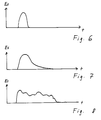
- Fig. 6-8
- Diagramme, bei denen der Wert eines Eingangssignals über die Zeit aufgetragen ist, bei Auftreffen eines Insekts, bei Auftreffen eines Wassertropfens und bei Auftreten eines im Wind bewegten Wassertropfens,
- Fig. 9
- einen Ablaufplan für die Arbeit mit einem Hintergrundspeicher,
- Fig. 10
- ein Blockschaltbild der Sensorvorrichtung.
- Fig. 1
- 1 shows a schematic circuit arrangement of the device for controlling a windshield wiper system,
- 2a, 2b, 2c
- Diagrams of the motor signal, the input signal and the counting over time,
- 3a, 3b
- Diagrams of the motor signal and the sensitivity over time,
- Fig. 4
- a diagram of the sensitivity over time at t v = 0,
- Fig. 5
- a diagram of the input signals over time,
- Fig. 6-8
- Diagrams in which the value of an input signal is plotted over time, when an insect hits, when a drop of water hits and when a drop of water moves in the wind,
- Fig. 9
- a schedule for working with a background memory,
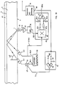
- Fig. 10
- a block diagram of the sensor device.
Gemäß Fig. 1 besitzt eine Einrichtung zur Steuerung einer Scheibenwischanlage einen Antriebsmotor M, der wenigstens einen Wischer, meist zwei Wischer 11 über einen Wischbereich 10a einer Scheibe führt. In dem Wischbereich 10a ist eine Sensorvorrichtung 12 angeordnet, wie sie aus dem DE-GM 93 09 837 bekannt ist. Insofern kann bezüglich dieser Sensorvorrichtung weitgehend auf diese Druckschrift verwiesen werden. Soweit erforderlich, wird jedoch auf die Einzelheiten der Sensorvorrichtung im folgenden eingegangen.According to FIG. 1, a device for controlling a windshield wiper system has a drive motor M which guides at least one wiper, usually two
Die Sensorvorrichtung 12 wird während eines Wischvorgungs vom Wischer 11 bei randständiger Anordnung wenigstens einmal überstrichen und, sofern sie an einer beliebigen Stelle im Wischbereich des Wischers angeordnet ist, zweimal überstrichen. Die Sensorvorrichtung wird von einem Belag oder einer Benetzung der Scheibe so beeinflußt, daß jede Beeinflussung ein Signal Es analog zur Tropfengröße oder -menge erzeugt. Mit dem Antriebsmotor M und der Sensorvorrichtung 12 ist eine Signalverarbeitungseinrichtung 13 gekoppelt, die die von der Sensorvorrichtung 12 erzeugten Signale in Steuersignale S für den Antriebsmotor M umformt. Die Einrichtung kann auch eine Schaltkontakteinrichtung, die ggf. wenigstens einer bestimmten Stellung des Wischers während des Wischvorgangs zugeordnet sein kann. Meist handelt es sich bei der Schaltkontakteinrichtung 14 um den Motorendschalter des Antriebsmotors M, bei dessen Betätigung der Wischer 11 sich in seiner Parkstellung befindet.The
Als Mittel zur Erkennung der Signale, die von der Sensorvorrichtung 12 während des Überstreichens durch den Wischer 11 erzeugt werden, ist der Zähler Z einer Zählanordnung 15 vorgesehen. Der Zähler zählt dabei sämtliche während eines Wischvorgangs von der Sensorvorrichtung 12 ermittelten Signale und vergleicht diese mit einem voreingestellten bestimmten Wert. Ein Überschreiten dieses Wertes löst einen Wischvorgang aus. Der bestimmte voreingestellte Wert ist jedoch größer als die Anzahl der Signale, die von der Sensorvorrichtung 12 während des Überstreichens des Wischers erzeugt werden. Nach Auslösen des folgenden Wischvorgangs, spätestens aber nach wenigstens einem Wischzyklus, wird der Wert der Zählanordnung 15 auf einen Ausgangswert zurückgestellt. Signal kann auch eine Schaltkontakteinrichtung 14 geben, sobald der Wischer z.B. in seiner Parkstellung ist.The counter Z of a
Die Sensorvorrichtung selbst arbeitet im Ausführungsbeispiel optoelektronisch, wobei durch ein Zusammenspiel von Strahlungssendern und Strahlungsempfängern wenigstens zwei Meßstrecken gebildet werden, die wechselweise über einen Taktgeber angesteuert werden. Eine Auswerteeinrichtung 16 detektiert die getakteten Signale, wobei die auftretenden Signale über eine Zeitkonstante, wie in dem DE-GM 93 09 837 beschrieben, zu 0 ausgeregelt werden. Dadurch ist es möglich, selbst starke Fremdstrahlung so auszublenden, daß Signale Es entstehen, die lediglich vom Belag und der Benetzung der Scheibe 10 abhängig sind. Vorteilhaft ist die Fähigkeit der Sensorvorrichtung 12, Signale analog zur Tropfengröße und -menge zu erzeugen unabhängig von der Arbeitsweise des Sensors (optisch, kapazitiv, usw.). Kleine Tröpfchen erzeugen kleine Signale, große Tropfen große Signale und bei Bewegung im Wind sogar mehrere Signale, so daß sich deutlich Qualität und Quantität der Benetzung erkennen läßt. Während im Stand der Technik ein Wischen erfolgt, sobald ein bestimmter Referenzwert unterschritten wird, kann hier innerhalb des verwertbaren Signalbereichs das Ansprechverhalten analog zum zeitlichen Ablauf einer erneuten Benetzung geregelt werden, während die Detektionsschwelle D z.B. nicht verändert wird. Eine Einstellanordnung stellt eine derart bemessene Strahlungsleistung der einzelnen Strahlungsquellen ein, daß bei unbenetztem sensoraktivem Bereich jede Meßstrecke einen Abschnitt des Detektionssignals erzeugt, dessen mittlerer Amplitudenwert gleich dem mittleren Amplitudenwert der den anderen Meßstrecken zugeordneten Abschnitten des Detektionssignals ist, und wobei eine Filterschaltung das getaktete Detektionssignal hinsichtlich des Unterschieds zwischen den den einzelnen Meßstrecken zugeordneten Abschnitten zur Erzeugung eines Steuersignals filtert. Hierzu wird im einzelnen auf das DE-GM 93 09 837 verwiesen, das hiermit ausdrücklich auch zum Gegenstand der vorliegenden Erfindung gemacht wird.In the exemplary embodiment, the sensor device itself works optoelectronically, at least two measuring sections being formed by an interaction of radiation transmitters and radiation receivers, which are alternately controlled by a clock generator. An
Bei der in Fig. 10 dargestellten Anordnung ist die Schalteranordnung zur Steuerung der beiden Strahlungsquellen 2.1 und 2.2 ein Taktgenerator 30 der an einem nicht invertierenden Ausgang 30.0 und an einem invertierenden Ausgang 30.1 abwechselnd einen Stromimpuls jeweils zur Anregung der Ausstrahlung der an den Ausgang angeschlossenen Strahlungsquelle für die Dauer des Stromimpulses erzeugt. Der eine Ausgang des Stromimpulsgenerators 30 enthält zur Einstellung des Stromwertes ein Stromstellglied 32, das durch ein Stellsignal Sr an seinem Stelleingang 47 verstellbar ist. Die Rückstrahlung dieser beiden Strahlungsquellen am Ankopplungsort des Strahlungsempfängers 16 wird von diesem in ein elektrisches Ausgangssignal S 16 gewandelt, das entsprechend zu der in Fig 3 dargestellten Anordnung über einen Verstärker 35 und einen Hoch- oder Bandpaß 36 als Detektionssignal SD an den Ausgang der Filterschaltung 36 gelangt. An den Ausgang der Filterschaltung 36 ist eine Signalzentrierstufe 48 angeschlossen, die die Änderungen des Detektionssignales SD am Ausgang der Filterschaltung 36 einer Mittenspannung Uz aufprägt. Im dargestellten Ausführungsbeispiel enthält die Signalzentrierstufe 48 einen Synchrondemodulator 49 mit zwei Demodulatorausgängen 49.1 und 49.2, die je einer Strahlungsquelle zugeordnet sind. Die Zuordnung erfolgt über einen Steuertakt S 30.0 des Stromimpulsgenerators 30, der auch die Abstrahlung der Strahlungsquellen steuert. Den Demodulatorausgängen 49.1 und 49.2 sind im dargestellten Ausführungsbeispiel Demodulationswertspeicher 50.1 und 50.2 nachgeschaltet, die den mittleren Amplitudenwert der von dem Synchrondemodulator 49 abgetasteten, den beiden Strahlungsquellen zugeordneten Signalabschnitten des Demodulationssignals SD momentan speichern und auf diese Weise einen Hüllkurvendemodulator bilden. Aus den momentanen mittleren Amplitudenwerten der beiden Detektionswertspeicher wird in einem anschließenden Operationsverstärker 51 der Differenzwert gebildet und einem Mittenwert aufgeprägt. Dieses so gebildete geglättete Detektionssignal SD m, das gegenüber dem Detektionssignal SD am Ausgang der Filterschaltung 36 wesentlich von Störungen befreit ist, wird sowohl einer Auswertanordnung 41 als auch einer Regelschaltung 52 mit einer hohen Regelzeitkonstanten Tv zugeführt. Im dargestellten Ausführungsbeispiel enthält die Regelschaltung ein Zeitkonstantenglied 53 und einen Vergleicher 54, der aus dem Vergleich mit einem Referenzsignal Sref ein Stellsignal Sr für den Stelleingang 47 des Stromstellgliedes 32 derart erzeugt, daß die Strahlungsleistung der mit dem Stromstellglied geregelten Strhlungsquelle 2.1 so verändert wird, daß der Unterschied der Detektionsamplitudenwerte am Ausgang der Signalzentrierstufe 48 gegen Null geht. Die Regelgeschwindigkeit, d.h. die Regelzeitkonstante Tv der Regelschaltung 52 ist hierbei so bemessen, daß sie um ein wesentliches Vielfaches größer ist als die langsamsten noch zu erfassenden Änderungen eines Benetzungsvorganges. Die Auswertanordnung 41 kann eingangsseitig auch unmittelbar mit dem Ausgang der beiden Detektionswertspeicher 50.1 und 50.2 verbunden werden, insbesondere dann, wenn mittels der Auswertanordnung die Benetzung gemessen werden soll. Die Regelzeitkonstante ist um ein wesentliches Vielfaches größer ist als eine Schwingungsperiode des Schaltfolgesignales, das die dem Strahlungsempfänger zugeordneten Strahlungsquellen oder Gruppen von Strahlungsquellen schaltet. Dadurch werden langsamere oder bleibende Änderungen im sensoraktiven Bereich der Platte oder Wand, die nicht von der Benetzung verursacht sind oder die Benetzung nicht betreffen, beim Erkennen oder Messen der Benetzung nicht berücksichtigt und Einflüsse infolge von Alterung, Verschmutzung oder Temperaturunterschieden können leicht eliminiert werden, die bekannten Systemen Probleme bereiten.In the arrangement shown in FIG. 10, the switch arrangement for controlling the two radiation sources 2.1 and 2.2 is a
Die vom Zähler Z ermittelten Werte können dann unmittelbar einem Digital-Analog-Wandler 19 zugeführt werden, der daraus Steuersignale S für den Antriebsmotor M bildet. Allgemein kann gelten, daß je höher der Zählerstand im Durchschnitt oder bei Beginn eines Wischvorgangs ist, umso öfter gewischt wird. Problemlos können sämtliche Signale während eines Wischvorgangs ausgewertet werden. Durch das automatische Rücksetzen, entweder zeitabhängig, steuerspannungsabhängig oder in Abhängigkeit der Wischerstellung, werden auch einzeln auftretende Signale sicher ermittelt. Im Ausführungsbeispiel wird dazu der ganzzahlige Abstand zwischen dem Ausgangswert A und dem Wert, bei dessen Überschreiten der Wischvorgang ausgelöst wird, gegenüber dem Wert erhöht, der der Anzahl des Überstreichens, also z.B. der Zahl 1 oder 2 entspricht. Das erste Signale kann dann z.B. einen Timer schalten, der den Ausgangswert A für einen bestimmten Zeitraum um 1 erhöht, wobei jedes weitere, über den Timer geführte, neu eintreffende Signal die Timerlaufzeit neu startet. Die eindeutige Detektionsmöglichkeit der Signale führt dazu, daß ein Einzelereignis, wie z.B. das Auftreffen eines Insekts gemäß Fig. 6 ein deutliches Einzelsignal ergibt, während bereits ein Tropfen und erst recht ein Tropfen im Wind gemäß den Fign. 7 und 8 längere bzw. mehrere Signale erzeugt, die den Zähler entsprechend hochzählen lassen, so daß der voreingestellte Wert überschritten wird. Ein unerwartetes Auslösen und damit verbundene Schreckmomente des Fahrzeugführeres werden vermieden.The values determined by the counter Z can then be fed directly to a digital-to-
Einstellmittel 18 können zur Regelung des Ansprechverhaltens der Sensorvorrichtung 12 vorgesehen sein. Diese Einstellmittel 18 können auch unmittelbar an der Sensorvorrichtung angeordnet sein und verringern nach einer vorgegebenen Zeit tv nach Beginn eines Wischvorgangs das Ansprechverhalten der Sensorvorrichtung in Abhängigkeit des Motorsignals Ms der Schaltkontakteinrichtung 14. Dies führt zu einer Verschiebung des Wertes, ab dem die vorhandenen Signale detektiert werden. So können innerhalb der einzeln anstehenden Signale Regelverläufe gebildet werden, die bereits den Tropfen entsprechenden Signale zu Auswertezwecken verändern. Innerhalb verwertbarer Signale wird die Erfassungsschwelle verschoben. Dies führt dazu, daß bei verringertem Ansprechverhalten große Tropfen aufgrund der Höhe und/oder Dauer des Signals zu einem Eingangssignal führen, während kleinere Tröpfchen keine Wirkung zeigen.Setting means 18 can be provided for regulating the response behavior of the
Dies kann entweder dadurch erfolgen, daß das Ansprechverhalten und die Empfindlichkeit der Sensorvorrichtung durch Regelung der Empfindlichkeit verringert wird, wodurch sich die Signale aufgrund einer geringeren Verstärkung mit einer geringeren Amplitude abzeichnen, oder daß die Regelzeitkonstante geregelt wird, so daß sich die Signale zeitlich kürzer abzeichnen. Alternativ können Signale mit einem unterschiedlichen Teilerverhältnis erfaßt werden. Allen Regelungen ist gemeinsam, daß die Einstellmittel 18 zur Regelung des Ansprechverhaltens der Einrichtung das Ansprechverhalten nach einer vorgegebenen Zeit tv, die ggf. auch Null sein kann und nach der der Wischer 11 seine Parkstellung verlassen hat oder nach der das Steuersignal dem Wischer Übermittelt worden ist, von einem Ausgangszustand mit empfindlichem Ansprechverhalten auf einen vorbestimmten Zwischenzustand mit unempfindlichem Ansprechverhalten regeln und anschließend innerhalb einer bestimmten Zeit t2 auf einen Endzustand zurückregeln, der vorzugsweise dem Ausgangszustand entspricht. Insofern kann auf ein Signal des Endschalters ggf. auch verzichtet werden.This can be done either by reducing the response and the sensitivity of the sensor device by regulating the sensitivity, as a result of which the signals are shown with a lower amplitude due to a lower amplification, or by regulating the control time constant so that the signals are shown to be shorter in time . Alternatively, signals with a different division ratio can be acquired. All regulations have in common that the setting means 18 for regulating the response behavior of the device, the response behavior after a predetermined time t v , which may also be zero and after which the
Eine Ausregelung der ermittelten Signale im Sensor über die Regelzeitkonstante erfolgt grundsätzlich so, daß der Differenzwert des Signals gegen Null geht, wobei bei einer langen Regelzeitkonstante der Differenzwert langsamer gegen Null geht als bei einer kurzen Regelzeitkonstante. Die Einstellmittel 18 regeln während eines Wischvorgangs die Regelzeitkonstante kürzer als zu einem Zeitpunkt, während dem keine Benetzung vorhanden ist. Allein schon dadurch ist es möglich, Veränderungen, die durch von selbst abtrocknende Schlieren nach dem Überwischen auftreten, aus den Meßsignalen auszublenden. Die Regelzeitkonstante wird von der Signalverarbeitungseinrichtung 13 in Abhängigkeit des Signals des Motorendschalters E und eines Zeitraums von ca. 10-30 Sekunden geregelt. Die Empfindlichkeit wird dadurch so verschoben, daß nach dem Zurückregeln nur große Tropfen erkannt werden. Als Nebeneffekt wird ein durch das Überstreichen der Sensorvorrichtung 12 durch den Wischer 11 erzeugtes Signal auswertbar, weil bei viel Regen auch ein großer Überwischimpuls erzeugt wird.The signals determined are regulated in the sensor via the control time constant in such a way that the difference value of the signal goes to zero, with a long control time constant the difference value going more slowly to zero than with a short control time constant. The setting means 18 regulate the regulating time constant shorter than during a wiping process a time during which there is no wetting. This alone makes it possible to mask out changes in the measurement signals that occur due to self-drying streaks after wiping. The control time constant is regulated by the
Alternativ oder ergänzend können auch Stellmittel 30 vorgesehen sein, die in Abhängigkeit eines Signals der Schaltkontakteinrichtung 14 ein Teilerverhältnis innerhalb einer vorbestimmten Zeit t2 bis auf 1:1 verringern, so daß zunächst mehrere Signale Es zu einem einzigen Signal führen, bis die Stellmittel 30 den Teiler auf 1 gesetzt haben. Dies führt dazu, daß entweder aufgrund eines Regens oder aufgrund größerer Tropfen, die aufgrund ihrer Bewegung im Wind mehrere Signale erzeugen, trotz des anfänglich hohen Teilers ein Signal aus mehreren entsteht oder ein Signal entsteht, sobald der Teiler nach einer bestimmten Zeit soweit verringert ist, daß ein einzelnes Signal weitergeleitet wird.As an alternative or in addition, actuating means 30 can also be provided which, depending on a signal from the
Im folgenden werden die ermittelten Ergebnisse anhand der Fign. 2a bis 5 näher erläutert. Fig. 2a zeigt zunächst das Motorsignal Ms, das sich über die Zeit ändert. Sobald der Scheibenwischermotor zum Zeitpunkt t1 eingeschaltet wird, ergibt sich ein Motorsignal Ms, das über den Wischzeitraum tw vorhanden ist. Das Auftreten dieses Motorsignals sorgt dafür, daß der Wert des Zählers Z auf den Ausgangswert A gestellt wird, der gemäß Fig. 2c minus 2 ist. Die Zahl minus 2 wird dabei dann gewählt, wenn der Wischer 11 die Sensorvorrichtung 12 im Wischbereich 10a zweimal überstreicht. In Fig. 2b sind ebenfalls über die Zeit aufgetretene Signale aufgezeichnet. Die ersten beiden Signale 20 und 21 werden dabei dadurch hervorgerufen, daß der Wischer die Sensorvorrichtung überstreicht. Jedes Signal führt dabei zu einem Puls als Eingangssignal Es in die Signalverarbeitungseinrichtung 13. Allein durch diese beiden Signale zählt die Zählanordnung 15 bis zum Wert 0 herauf, der dem voreingestellten bestimmten Wert entspricht. Die beiden weiter auftretenden Signale 22 erhöhen dann diesen Wert weiter, so daß in Abhängigkeit des Wertes des Zählers Z der Digital-Analog-Wandler 19 nun Steuersignale S für den Antriebsmotor erzeugt, die wiederum zu einem Einschalten des Wischers führen, was eine Rückstellung des Zählers auf den Ausgangswert minus 2 zur Folge hat.In the following, the results determined are based on FIGS. 2a to 5 explained in more detail. Fig. 2a first shows the motor signal Ms, which changes over time. As soon as the windshield wiper motor is switched on at time t 1 , a motor signal Ms results which is present over the wiping period t w . The occurrence of this motor signal ensures that the value of the counter Z is set to the initial value A, which is minus 2 according to FIG. 2c. The number minus 2 is selected when the
Diese Zählanordnung 15 kann gemeinsam mit einer Empfindlichkeitsregelung eingesetzt werden, wie sie sich aus den Fign. 3a bis 5 ergibt. Die Beispiele zeigen eine Regelung der Empfindlichkeit, also eine Verringerung der Amplitude. Eine Veränderung der Regelzeitkonstante bzw. des Teilerverhältnisses wirkt sich jedoch ähnlich aus. In Fig. 3a ist das Motorsignal aufgetragen, das zum Zeitpunkt t1 über die Einstellmittel 18 zur Regelung des Ansprechverhaltens die Empfindlichkeit E gemäß Fig. 3b von einem Maximalwert Emax auf einen Minimalwert Emin geregelt. Dieser Minimalwert wird gemäß Fig. 3b zunächst über eine vorgegebene Zeit tv aufrechterhalten. In einem an den Wischvorgang anschließenden Zeitraum t2, der in der Praxis z.B. 10-30 Sekunden betragen kann, wird die Empfindlichkeit E allmählich wieder auf den Wert Emax überführt.This
Gemäß Fig. 4 besteht die Möglichkeit, bei tv=0 das Ansprechverhalten bereits während des Wischvorgangs wieder allmählich höher werden zu lassen. Während des gesamten Zeitraums werden die kontinuierlich ermittelten Signale einem Speicher zugeführt, der bei Überschreiten eines voreingestellten Werts einen Wischvorgang auslöst. Dadurch werden bei starkem Regen während des gesmten Wischvorgangs Signale ermittelt, die ein feinfühliges Steuern der Scheibenwischanlage ermöglichen. Um ggf. ein rasches Reagieren der Scheibenwischersteuerung z.B. bei der Vorbeifahrt an einem Lkw oder einer Ausfahrt aus einem Tunnel zu erzielen, besteht ergänzend die Möglichkeit kurz nach dem Wischvorgang auftretende Signale unmittelbar zur Steuerung der Scheibenwischanlage in den Speicher der Steuereinheit 15 zu laden.According to FIG. 4, there is the possibility, at t v = 0, of gradually increasing the response behavior again during the wiping process. Throughout the entire period, the continuously ascertained signals are fed to a memory, which triggers a wiping process when a preset value is exceeded. As a result, signals are determined during heavy rain during the entire wiping process, which enable sensitive control of the windshield wiper system. In order to possibly react quickly to the windshield wiper control, for example when driving past a truck or exiting a tunnel, there is the additional possibility of loading signals that occur shortly after the wiping process directly for controlling the windshield wiper system into the memory of the
Das Ergebnis ergibt sich aus Fig. 5. Wie zuvor beschrieben, wird gemäß der gestrichelten Linie die Empfindlichkeit, also das Ansprechverhalten der gesamten Sensorvorrichtung geregelt verändert. Signale führen zu einer Reaktion der Steuerung, sobald die Detektionsschwelle überschritten wird, wobei auch mehrere Signale in einem Speicher gespeichert werden können, um einen weichen, gleichmäßigen Wischablauf zu erzielen. Zu Beginn setzt auf der linken Seite von Fig. 5 ein Regen ein, der beim Peak P1 ein Wischen auslöst, da die Detektionsschwelle überschritten wird. Der Fahrzeugbenutzer hätte seinen Wischer ebenfalls jetzt aufgrund der Sichtbehinderung betätigt. Mit tv=0 wird die Empfindlichkeit zu Beginn des Wischvorgangs, also zum Zeitpunkt t1 vom Ausgangszustand auf einen Zwischenzustand heruntergeregelt. Als Folge davon erscheinen die folgenden Tropfen in der Amplitude kleiner. Handelt es sich um einen starken Regen, so würden sie dennoch sofort wieder die Detektionsschwelle D erreichen. Die Empfindlichkeit steigt allmählich wieder und würde einen Endzustand maximaler Empfindlichkeit Emax wieder erreichen, der dem Ausgangszustand entspricht, wenn nicht ein Tropfen als Peak P2 die Detektionsschwelle überschreiten würde. Sofort fällt die Empfindlichkeit durch den erneut ausgelösten Wischvorgang auf den Zwischenzustand minimaler Empfindlichkeit Emin. Die Zeit zwischen den Peaks oder zwischen dem Verringern der Empfindlichkeit registriert die Steuerung als nächstes Wischintervall mit der Intervallzeit ti1. Den während eines Regens veränderlichen Bedingungen würde dadurch Rechnung getragen, daß, wenn der zweite Peak bereits früher die Detektionsschwelle erreicht hätte, z.B. der gestrichelt dargestellte Peak P3, sich die Intervallzeit ti2 ergeben hätte.The result is shown in FIG. 5. As described above, the sensitivity, that is to say the response behavior of the entire sensor device, is changed in a controlled manner according to the dashed line. Signals lead to a reaction of the control as soon as the detection threshold is exceeded, whereby several signals can also be stored in a memory in order to achieve a smooth, even wiping process. At the beginning, a rain sets in on the left side of FIG. 5, which triggers a wiping at the peak P1, since the detection threshold is exceeded. The vehicle user would also have operated his wiper now because of the visual impairment. With t v = 0, the sensitivity at the beginning of the wiping process, that is to say at time t 1 , is reduced from the initial state to an intermediate state. As a result, the following drops appear smaller in amplitude. If it is heavy rain, they would still reach detection threshold D again immediately. The sensitivity gradually increases again and would reach a final state of maximum sensitivity E max which corresponds to the initial state if a drop as peak P2 did not exceed the detection threshold. As a result of the wiping process triggered again, the sensitivity immediately falls to the intermediate state of minimal sensitivity E min . The control registers the time between the peaks or between the reduction in sensitivity as the next wiping interval with the interval time ti 1 . The changing conditions during a rain would be taken into account by the fact that if the second peak had already reached the detection threshold earlier, for example the peak P 3 shown in broken lines, the interval time ti 2 would have resulted.
Die Zählanordnung 15 kann eine erste Speichereinheit sein, die bei Überschreiten eines vorgegebenen Wertes V und/oder nach einer vorgegebenen Anzahl von ggf. innerhalb einer bestimmten Zeit aufeinanderfolgenden Wischvorgängen über Signalübertragungsmittel weitere Signale Sw an einen Hintergrundspeicher 25 überträgt, dessen Inhalt ebenfalls die Erzeugung von Steuersignalen ggf. auch nach Entladen der Speichereinheit beeinflußt.The counting
Der schematische Arbeitsablauf einer derartigen Vorrichtung ergibt sich aus Fig. 9. Sobald Signale Es von der Sensorvorrichtung ermittelt werden, wird die Zählanordnung als Speichereinkeit durch START gestartet. Die Eingangssignale werden eingelesen und ergeben die ganzzahlige Zahl n. Nach Abzug des Ausgangswertes A, der z.B die vom Überstreichen hervorgerufenen Signale widerspiegelt, ergibt sich die tatsächliche während eines Wischvorgangs eingegangene Anzahl X von Signalen. Ist dieser Wert X kleiner 0, kann dies grundsätzlich zur Beendigung des Wischens oder überhaupt nicht zum Start des Antriebsmotors führen. Ist X größer 0 wird je nach der Anzahl der kruzfristig ggf. während eines Wischvorgangs auftretenden Signale entweder die Intervallschaltung des Scheibenwischers mit einem von der Anzahl der Signale abhängigen Zeitintervall ausgelöst oder bei einer großen Anzahl von Signalen z.B. über 13 wird sofort, z.B. bei einer Vorbeifahrt an einem Lkw ein Dauerwischen ausgelöst.The schematic workflow of such a device results from FIG. 9. As soon as signals Es are determined by the sensor device, the counting arrangement is started as a storage unit by START. The input signals are read in and result in the integer number n. After deducting the output value A, which, for example, reflects the signals caused by the sweep, the actual number X of signals received during a wiping process results. If this value X is less than 0, this can in principle lead to the end of the wiping or not to the start of the drive motor at all. If X is greater than 0, depending on the number of signals occurring in the short term, possibly during a wiping process, either the interval switching of the windshield wiper is triggered with a time interval dependent on the number of signals, or, for a large number of signals, e.g. over 13 is immediately, e.g. permanent wiping triggered when a truck drives past.
Gleichzeitig wird überprüft, ob der Wert X größer als ein vorgegebener Schwellwert V ist, wobei hier ergänzend oder alternativ auch die Anzahl der unmittelbar aufeinanderfolgenden Wischvorgänge herangezogen werden kann. Ist der Wert V überschritten oder erreicht wird der Wert des Hintergrundspeichers 25 erhöht, wobei vorzugsweise ein Wert gewählt ist, der kleiner ist als der Gesamtinhalt des Speichers, um ein flexibles Verhalten dieses Hintergrundspeichers zu erzielen. Z.B. kann der Wert um 2 erhöht werden. In einem anschließenden Schritt wird dieser Wert dann z.B. um 1 verringert, sobald ein Signal von der Schaltkontakteinrichtung gegeben wird.At the same time, a check is carried out to determine whether the value X is greater than a predefined threshold value V, wherein the number of immediately successive wiping operations can also be used here in addition or alternatively. If the value V is exceeded or reached, the value of the background memory 25 is increased, a value which is preferably chosen to be smaller than the total content of the memory in order to achieve a flexible behavior of this background memory. E.g. the value can be increased by 2. In a subsequent step, this value is then e.g. reduced by 1 as soon as a signal is given by the switch contact device.
Abschließend wird geprüft, ob nicht nur X gleich 0 ist, sondern auch der Wert des Hintergrundspeichers wieder 0 ist. Erst wenn beide Bedingungen erfüllt sind, stoppt der Antriebsmotor.Finally, it is checked whether not only X is 0, but also the value of the background memory is 0 again. The drive motor only stops when both conditions are met.
Durch diesen Hintergrundspeicher 25 ist eine allmähliche Nachführung der Wischbewegungen möglich, da auch in der Natur ein Regen nicht schlagartig einsetzt und aufhört, so daß ein geregeltes Nachwischen nach einem Regen erzielt wird. Andererseits kann jedoch die im Vordergrund agierende Speichereinheit, hier die Zählanordnung blitzartig auf Spritzwasser reagieren.This background memory 25 enables the wiping movements to be tracked gradually, since rain does not suddenly begin and stop in nature, so that a regular wiping after rain is achieved. On the other hand, however, the storage unit operating in the foreground, here the counting arrangement, can react in a flash to splash water.
Bei Erreichen des bestimmten Wertes des Zählers (Z), also z.B. seines Maximalwertes, erfährt die Steuereinheit, daß eine entsprechende Benetzung vorhanden ist, die einen weiteren Wischvorgang erforderlich macht. Wird dieser Wert jedoch erreicht, bevor der vorausgehende Wischvorgang beendet ist, ist eine derartige Benetzung vorhanden, daß der Wischer im Dauerbetrieb bleiben muß. Insofern führt dieses vorzeitige erneute Erreichen des Wertes zu einer derartigen z.B. Verlängerung des Steuersignals (S), daß der Antriebsmotor (M) im Dauerbetrieb bleibt. Dazu kann z.B. die Zeit in der die Steuerspannung anliegt entsprechend beeinflußt werden.When the specific value of the counter (Z) is reached, e.g. of its maximum value, the control unit learns that a corresponding wetting is present which makes a further wiping process necessary. However, if this value is reached before the previous wiping process has ended, the wetting is such that the wiper must remain in continuous operation. In this respect, this premature re-reaching of the value leads to e.g. Extension of the control signal (S) that the drive motor (M) remains in continuous operation. For this, e.g. the time during which the control voltage is applied can be influenced accordingly.
Claims (13)
- Apparatus for controlling a windscreen wiper system, having- a drive motor (M) for at least one wiper (11), which sweeps over a wiping area (10a) of a windscreen (10);- a sensor device (12), which is disposed in the wiping area (10a), and over which the wiper (11) sweeps at least once during a wiping operation, said sensor device generating signals which are influenced by the external surface or the wetting of the windscreen (10);- a signal processing device (13), which is coupled to the drive motor (M) and sensor device (12), and which converts the signals (Es), generated by the sensor device (12), into control signals (S) for the drive motor (M); and- means for detecting the signals (Es), which are generated by the sensor device (12) while the wiper (11) sweeps over it;characterised in that a counting arrangement (15) is provided, the counter (Z) of which, as a means for detecting the signals caused by the wiper sweeping over this sensor device, counts the signals (Es) provided by the sensor device (12) during a wiping operation, wherein exceeding of a specific value of the counter (Z) trips a further wiping operation, which value is at least greater than the number of signals which are generated by the sensor device (12) alone, so that the wiper (11) itself sweeps over the sensor device (12), and in that the value of the counting arrangement (15) can be reset to a starting value.
- Apparatus according to claim 1, characterised in that, when the specific value of the counter (Z) is reached, a further wiping operation is started, and in that, if the specific value is reached before the end of the preceding wiping operation, the control signal (S) is generated such that the drive motor (M) remains in continuous operation.
- Apparatus according to claim 1, characterised in that a limit switch of the drive motor (M), upon the actuation of which the wiper (11) is in its parking position, resets the value of the counting arrangement (15).
- Apparatus according to claim 1, characterised in that the optoelectronic sensor device (12) has a plurality of radiation emitters and at least one radiation receiver or at least one radiation emitter and a plurality of radiation receivers, which form at least two measurement paths which are triggered via a timing generator, and in that an evaluation device (16) detects the timed signals and supplies them to the signal processing device (13), an adjusting arrangement (32) being provided for adjusting a radiation output, thus dimensioned, of the individual radiation sources, in that, when the sensor-active area is not wetted, each measurement path generates one portion of the detection signal, the mean amplitude value of which is equal to the mean amplitude value of the portions of the detection signal associated with the other measurement paths, and a filter circuit filtering the timed detection signal with respect to the difference between the portions associated with the individual measurement paths to generate a control signal.
- Apparatus according to claim 1, characterised in that the integral spacing between the starting value (A) and the value, the exceeding of which trips the wiping operation, is greater by at least 1 than the number of signals which the wiper (11) generates on sweeping over the sensor device (12)
- Apparatus according to claim 5, characterised in that a first signal switches a timer (17), which raises the starting value by at least 1 for a preadjustable period of time, each newly arriving signal being likewise carried via the timer and restarting the timer running time.
- Apparatus according to claim 1, characterised in that the sensor device (12) generates signals analogous to the droplet size and number, and in that adjusting means (18) are provided for regulating the response behaviour of the apparatus, which means regulate the response behaviour after a prescribed time (tv), after which the wiper (11) is started, from a starting state with a sensitive response behaviour to a predetermined intermediate state with an insensitive response behaviour, and subsequently regulate it back to a final state with a sensitive response behaviour within a specific time (t2), which behaviour preferably corresponds to the starting state.
- Apparatus according to claim 7, characterised in that the adjusting means (18) for regulating the response behaviour reduce the response behaviour again to the intermediate state before the starting state is reached if the signals (Es) exceed a detection threshold, and in that the time between when the intermediate state is first reached and is reached for a second time, at tv = 0, is the time interval (ti) of the wiper.
- Apparatus according to claim 7, characterised in that the adjusting means (18) for regulating the response behaviour regulate the response behaviour and the sensitivity of the sensor device by reducing the amplification of the signals and/or regulate such by reducing the regulating time constant, within which arriving signals (Es) are corrected.
- Apparatus according to claim 7, characterised in that the adjusting means (18) for regulating the response behaviour include control means (30), which reduce a divider ratio within the specific time (t2) down to 1:1, so that initially a plurality of signals (Es) lead to a single signal until the control means (30) have set the divider to 1.
- Apparatus according to claim 1, characterised in that the counting arrangement (15) is a first memory unit, and in that, if a prescribed further value (V) is exceeded and/or after a prescribed number of wiping operations, which possibly succeed one another within a specific unit of time, signal transmitting means transmit further signals (Sw) to a background memory (25), the contents of which likewise influence the generation of control signals, possibly also after unloading of the memory unit.
- Apparatus according to claim 11, characterised in that, as soon as the further value or the number of wiping operations is exceeded, the signal transmitting means transmit a limited signal value (Y) to the background memory (25), which value is smaller than its maximum memory contents.
- Apparatus according to claim 11, characterised in that the value (w) of the digital background memory (25) is reduced, upon each wiping operation performed, by a prescribed third value until it is completely unloaded.
Applications Claiming Priority (7)
| Application Number | Priority Date | Filing Date | Title |
|---|---|---|---|
| DE9309837U DE9309837U1 (en) | 1993-07-02 | 1993-07-02 | Arrangement for measuring or detecting the wetting of a wall or plate which is permeable to a specific radiation |
| DE9309837U | 1993-07-02 | ||
| DE4403221 | 1994-02-03 | ||
| DE4403221A DE4403221A1 (en) | 1993-07-02 | 1994-02-03 | Arrangement for measuring or detecting a change in a back-scattering element |
| DE4411772A DE4411772A1 (en) | 1993-07-02 | 1994-04-06 | Device for controlling a window wiping system |
| DE4411772 | 1994-04-06 | ||
| PCT/DE1994/000710 WO1995001270A1 (en) | 1993-07-02 | 1994-06-18 | Device for controlling a windscreen-washer installation |
Publications (3)
| Publication Number | Publication Date |
|---|---|
| EP0705186A1 EP0705186A1 (en) | 1996-04-10 |
| EP0705186B1 true EP0705186B1 (en) | 1997-03-12 |
| EP0705186B2 EP0705186B2 (en) | 2002-09-11 |
Family
ID=27206041
Family Applications (1)
| Application Number | Title | Priority Date | Filing Date |
|---|---|---|---|
| EP94918290A Expired - Lifetime EP0705186B2 (en) | 1993-07-02 | 1994-06-18 | Device for controlling a windscreen-washer installation |
Country Status (6)
| Country | Link |
|---|---|
| US (1) | US5726547A (en) |
| EP (1) | EP0705186B2 (en) |
| JP (1) | JPH09500345A (en) |
| AU (1) | AU6968394A (en) |
| ES (1) | ES2102230T5 (en) |
| WO (1) | WO1995001270A1 (en) |
Families Citing this family (18)
| Publication number | Priority date | Publication date | Assignee | Title |
|---|---|---|---|---|
| US6118383A (en) * | 1993-05-07 | 2000-09-12 | Hegyi; Dennis J. | Multi-function light sensor for vehicle |
| KR19990063055A (en) * | 1997-12-17 | 1999-07-26 | 마쯔무라 미노루 | Drip Insensitive Wiper Control |
| DE19815746C1 (en) * | 1998-04-08 | 1999-11-04 | Bosch Gmbh Robert | Sensor device for detecting wetting on a pane |
| DE19842064A1 (en) * | 1998-09-15 | 2000-03-16 | Bosch Gmbh Robert | Automatic activation apparatus for device, particularly windscreen wiper motor, on a motor vehicle, has |
| JP2002123304A (en) * | 2000-10-13 | 2002-04-26 | Yazaki Corp | Function selection control system |
| SE0101555D0 (en) * | 2001-05-04 | 2001-05-04 | Amersham Pharm Biotech Ab | Fast variable gain detector system and method of controlling the same |
| DE102004010492A1 (en) | 2004-03-04 | 2005-09-22 | Robert Bosch Gmbh | Rain sensor, in particular for a motor vehicle |
| JP4779860B2 (en) * | 2006-08-03 | 2011-09-28 | 株式会社デンソー | Raindrop amount detection device and wiper control device |
| US7679304B2 (en) * | 2006-09-08 | 2010-03-16 | Hasenberg, Inc. | Intermittent wiper control device |
| FR2937128B1 (en) * | 2008-10-14 | 2010-12-31 | Continental Automotive France | DEVICE FOR DETECTING AN ENVIRONMENTAL PARAMETER |
| FR2932258A1 (en) * | 2008-10-14 | 2009-12-11 | Continental Automotive France | Environment parameter e.g. rain, detecting device for convertible motor vehicle, has comparison unit providing control signal using operation setting unit, where signal adopts active state based on number of crossings exceeding threshold |
| CN102224041B (en) * | 2008-11-20 | 2013-10-16 | 埃尔莫斯半导体公司 | Interference-compensated sensor |
| JP2011122867A (en) * | 2009-12-09 | 2011-06-23 | Seiko Epson Corp | Optical position detection device and display device with position detection function |
| JP2011122870A (en) * | 2009-12-09 | 2011-06-23 | Seiko Epson Corp | Optical position detection device and projection display device |
| JP5741088B2 (en) | 2011-03-14 | 2015-07-01 | セイコーエプソン株式会社 | Position detection system and projection display system |
| CN105300705B (en) * | 2015-10-08 | 2017-08-25 | 上汽大众汽车有限公司 | Wiper experimental rig |
| FR3050889A1 (en) * | 2016-04-27 | 2017-11-03 | STMicroelectronics (Alps) SAS | OPTICAL EMISSION CIRCUIT IN CRENEAUX |
| EP3741630B1 (en) | 2019-05-21 | 2024-04-10 | TE Connectivity Sensors France | Real-time, fine adjustment of driver current of a light emitting device of an optical rain sensor |
Citations (14)
| Publication number | Priority date | Publication date | Assignee | Title |
|---|---|---|---|---|
| US216341A (en) * | 1879-06-10 | Improvement in combined spring and dead bolts | ||
| DE2630470A1 (en) * | 1976-07-07 | 1978-01-12 | Schmidt Karl Heinz | Automatic control for windscreen wipers - uses capacitance monitors and impulse control to differentiate between fine and large raindrops |
| EP0102622A2 (en) * | 1982-09-02 | 1984-03-14 | Nissan Motor Co., Ltd. | Wiper speed control system for an automotive windshield wiper |
| DE3314770A1 (en) * | 1983-04-23 | 1984-10-31 | Sidler GmbH & Co, 7400 Tübingen | Device for controlling a motor of a windscreen wiper |
| US4495452A (en) * | 1981-12-08 | 1985-01-22 | Boegh Peterson Allan | Windshield wiper control having a sensor and a repeatedly renewed offset signal |
| US4867561A (en) * | 1986-08-22 | 1989-09-19 | Nippondenso Co., Ltd. | Apparatus for optically detecting an extraneous matter on a translucent shield |
| US4916374A (en) * | 1989-02-28 | 1990-04-10 | Donnelly Corporation | Continuously adaptive moisture sensor system for wiper control |
| WO1990003903A1 (en) * | 1988-10-14 | 1990-04-19 | Millerd Donald L | Moisture-responsive control system |
| WO1990008680A2 (en) * | 1989-01-26 | 1990-08-09 | Etablissement Voralp | Device for controlling a driving means for a vehicle accessory |
| US5057754A (en) * | 1988-10-14 | 1991-10-15 | Mist-Defy'r, Inc. | Moisture-sensing window cleaning control system |
| DE3902231C2 (en) * | 1989-01-26 | 1991-11-14 | Etablissement Voralp, Schaan, Li | |
| DE4141348A1 (en) * | 1991-12-14 | 1993-06-17 | Kostal Leopold Gmbh & Co Kg | Vehicle windscreen wiper controller - uses opto-electronic sensor to detect water on screen only between wiping cycles, and operates wiper motor accordingly |
| DE9309837U1 (en) * | 1993-07-02 | 1993-09-02 | Reime Gerd | Arrangement for measuring or detecting the wetting of a wall or plate which is permeable to a specific radiation |
| WO1995021078A1 (en) * | 1994-02-05 | 1995-08-10 | Robert Bosch Gmbh | Device for operating a windscreen wiper in intermittent and continuous modes |
Family Cites Families (34)
| Publication number | Priority date | Publication date | Assignee | Title |
|---|---|---|---|---|
| DE2200878A1 (en) * | 1972-01-08 | 1973-08-23 | Licentia Gmbh | PHOTOELECTRIC BARRIER |
| CH568627A5 (en) * | 1974-07-15 | 1975-10-31 | Cerberus Ag | |
| DE3140865A1 (en) * | 1981-10-14 | 1983-05-11 | Hans-Wolfgang 8000 München Diesing | Circuit arrangement for pulsed reflected light barriers |
| DE3203091C2 (en) * | 1982-01-30 | 1985-06-13 | Vdo Adolf Schindling Ag, 6000 Frankfurt | Device for controlling the windshield cleaning system of a motor vehicle |
| DE3218279A1 (en) * | 1982-05-13 | 1983-11-17 | Manfred 1000 Berlin Lau | Automatic interval switch for windscreen wipers |
| DE3235590C2 (en) * | 1982-09-25 | 1984-11-22 | Fraunhofer-Gesellschaft zur Förderung der angewandten Forschung e.V., 8000 München | Device for the optical detection of foreign bodies |
| JPS59140146A (en) * | 1983-01-28 | 1984-08-11 | Jidosha Denki Kogyo Co Ltd | Windshield wiper intermittent driving controller |
| JPS6111637A (en) * | 1984-06-27 | 1986-01-20 | Nec Corp | Liquid body sensor |
| US4620141A (en) * | 1985-07-03 | 1986-10-28 | Vericom Corp. | Rain-controlled windshield wipers |
| DE3619208A1 (en) * | 1986-06-07 | 1987-12-10 | Bosch Gmbh Robert | DEVICE FOR THE OPTICAL DETECTION OF FOREIGN BODIES |
| DE3715798A1 (en) * | 1987-05-12 | 1988-01-07 | Erich Ing Grad Huber | Optoelectronic device for detecting the polluting (fouling) of transparent protective panes and initiating the cleaning measures |
| DE3722510A1 (en) * | 1987-07-08 | 1989-01-26 | Bosch Gmbh Robert | DEVICE FOR RAIN-DEPENDENT SWITCHING ON AND OFF OF AN ELECTRIC WIPER MOTOR |
| IT212441Z2 (en) * | 1987-07-31 | 1989-07-04 | Veglia Borletti Srl | DEVICE SENSOR OF THE PRESENCE OF DROPS OF WATER ON A VEHICLE CRYSTAL AND EQUIPMENT OF A WINDSCREEN WIPER EQUIPPED WITH THE SAID DEVICE |
| IT212332Z2 (en) * | 1987-07-31 | 1989-07-04 | Veglia Borletti Srl | DEVICE SENSOR OF THE PRESENCE OF WATER DROPS ON A VEHICLE CRYSTAL AND EQUIPMENT OF A WINDSCREEN WIPER EQUIPPED WITH THE SAID DEVICE |
| DE3733762A1 (en) * | 1987-10-06 | 1989-04-20 | Karl Gerhard | WASHER SOIL DETECTOR |
| DE3800327A1 (en) * | 1988-01-08 | 1989-07-27 | Bosch Gmbh Robert | METHOD FOR OPERATING A WIPER AND DEVICE FOR IMPLEMENTING THE METHOD |
| JPH0238167A (en) * | 1988-07-29 | 1990-02-07 | Stanley Electric Co Ltd | Rain drop sensor |
| DE3941905A1 (en) * | 1988-12-19 | 1990-06-21 | Fujitsu Ten Ltd | WINDOW WIPER CONTROL DEVICE |
| US4960996A (en) * | 1989-01-18 | 1990-10-02 | Hochstein Peter A | Rain sensor with reference channel |
| US4956591A (en) * | 1989-02-28 | 1990-09-11 | Donnelly Corporation | Control for a moisture sensor |
| FR2648096B1 (en) * | 1989-06-12 | 1991-08-23 | Valeo Systemes Dessuyage | WINDSHIELD WIPER SYSTEM WITH RAIN SENSOR |
| DE3935807A1 (en) * | 1989-10-27 | 1991-05-02 | Swf Auto Electric Gmbh | Vehicular windscreen wiper with variable-gain rain detector - exploits excitation of vibrations of diaphragm by rain-drop impact with allowance for high-speed noise |
| US5059877A (en) * | 1989-12-22 | 1991-10-22 | Libbey-Owens-Ford Co. | Rain responsive windshield wiper control |
| DE4000736A1 (en) * | 1990-01-12 | 1991-07-18 | Vdo Schindling | METHOD AND ARRANGEMENT FOR CONTROLLING A WIPER |
| DE4000735A1 (en) * | 1990-01-12 | 1991-07-18 | Vdo Schindling | METHOD AND ARRANGEMENT FOR CONTROLLING A WIPER |
| DE4018903A1 (en) * | 1990-06-13 | 1991-12-19 | Bosch Gmbh Robert | Vehicle windscreen wiper operating appts. - contains sensor for influencing intervals according to screen fouling, moisture or rain |
| US5252898A (en) * | 1990-06-13 | 1993-10-12 | Robert Bosch Gmbh | Method of operating a windshield wiper |
| DE4036407C2 (en) * | 1990-11-15 | 1994-06-01 | Telefunken Microelectron | Sensor system |
| DE4217390C2 (en) * | 1991-06-24 | 1994-06-16 | Kostal Leopold Gmbh & Co Kg | Device for controlling a windshield wiper system |
| DE4120750A1 (en) * | 1991-06-24 | 1993-01-07 | Kostal Leopold Gmbh & Co Kg | DEVICE FOR CONTROLLING A WINDOW WIPER |
| DE4134432A1 (en) * | 1991-10-18 | 1993-04-22 | Daimler Benz Ag | METHOD FOR ADAPTING THE RESPONSE SENSITIVITY OF A REPUTATION SENSOR SYSTEM TO ENVIRONMENTAL CONDITIONS AND SENSOR SYSTEM WITH A DEPOSITION SENSOR |
| DE4231763C2 (en) * | 1992-09-23 | 1995-07-06 | Kostal Leopold Gmbh & Co Kg | Device for controlling a windshield wiper system |
| DE4209680A1 (en) * | 1992-03-25 | 1993-09-30 | Bosch Gmbh Robert | rain sensor |
| DE4229491A1 (en) * | 1992-09-04 | 1993-01-07 | Steinbacher Peter Dipl Ing Fh | Vehicular windscreen wiper controller with optical moisture detector - responds to encoded light pulse reflection in raindrops with increase in frequency of wiper motor operation |
-
1994
- 1994-06-18 WO PCT/DE1994/000710 patent/WO1995001270A1/en active IP Right Grant
- 1994-06-18 AU AU69683/94A patent/AU6968394A/en not_active Abandoned
- 1994-06-18 ES ES94918290T patent/ES2102230T5/en not_active Expired - Lifetime
- 1994-06-18 EP EP94918290A patent/EP0705186B2/en not_active Expired - Lifetime
- 1994-06-18 US US08/578,683 patent/US5726547A/en not_active Expired - Lifetime
- 1994-06-18 JP JP7503209A patent/JPH09500345A/en active Pending
Patent Citations (14)
| Publication number | Priority date | Publication date | Assignee | Title |
|---|---|---|---|---|
| US216341A (en) * | 1879-06-10 | Improvement in combined spring and dead bolts | ||
| DE2630470A1 (en) * | 1976-07-07 | 1978-01-12 | Schmidt Karl Heinz | Automatic control for windscreen wipers - uses capacitance monitors and impulse control to differentiate between fine and large raindrops |
| US4495452A (en) * | 1981-12-08 | 1985-01-22 | Boegh Peterson Allan | Windshield wiper control having a sensor and a repeatedly renewed offset signal |
| EP0102622A2 (en) * | 1982-09-02 | 1984-03-14 | Nissan Motor Co., Ltd. | Wiper speed control system for an automotive windshield wiper |
| DE3314770A1 (en) * | 1983-04-23 | 1984-10-31 | Sidler GmbH & Co, 7400 Tübingen | Device for controlling a motor of a windscreen wiper |
| US4867561A (en) * | 1986-08-22 | 1989-09-19 | Nippondenso Co., Ltd. | Apparatus for optically detecting an extraneous matter on a translucent shield |
| US5057754A (en) * | 1988-10-14 | 1991-10-15 | Mist-Defy'r, Inc. | Moisture-sensing window cleaning control system |
| WO1990003903A1 (en) * | 1988-10-14 | 1990-04-19 | Millerd Donald L | Moisture-responsive control system |
| WO1990008680A2 (en) * | 1989-01-26 | 1990-08-09 | Etablissement Voralp | Device for controlling a driving means for a vehicle accessory |
| DE3902231C2 (en) * | 1989-01-26 | 1991-11-14 | Etablissement Voralp, Schaan, Li | |
| US4916374A (en) * | 1989-02-28 | 1990-04-10 | Donnelly Corporation | Continuously adaptive moisture sensor system for wiper control |
| DE4141348A1 (en) * | 1991-12-14 | 1993-06-17 | Kostal Leopold Gmbh & Co Kg | Vehicle windscreen wiper controller - uses opto-electronic sensor to detect water on screen only between wiping cycles, and operates wiper motor accordingly |
| DE9309837U1 (en) * | 1993-07-02 | 1993-09-02 | Reime Gerd | Arrangement for measuring or detecting the wetting of a wall or plate which is permeable to a specific radiation |
| WO1995021078A1 (en) * | 1994-02-05 | 1995-08-10 | Robert Bosch Gmbh | Device for operating a windscreen wiper in intermittent and continuous modes |
Also Published As
| Publication number | Publication date |
|---|---|
| EP0705186B2 (en) | 2002-09-11 |
| US5726547A (en) | 1998-03-10 |
| ES2102230T3 (en) | 1997-07-16 |
| EP0705186A1 (en) | 1996-04-10 |
| JPH09500345A (en) | 1997-01-14 |
| AU6968394A (en) | 1995-01-24 |
| WO1995001270A1 (en) | 1995-01-12 |
| ES2102230T5 (en) | 2003-05-01 |
Similar Documents
| Publication | Publication Date | Title |
|---|---|---|
| DE4411770C2 (en) | Device for controlling a windshield wiper system | |
| EP0705186B1 (en) | Device for controlling a windscreen-washer installation | |
| EP0706648B1 (en) | Arrangement for measuring or detecting a change in a retro-reflective component | |
| DE4036407C2 (en) | Sensor system | |
| EP0871579B1 (en) | Control device for an optical sensor | |
| DE3941905C2 (en) | ||
| DE4141348C2 (en) | Device for controlling a windshield wiper system | |
| DE4339574C2 (en) | Evaluation device for signals, which were determined by a measuring arrangement for measuring or recognizing the wetting of a surface | |
| DE19526249A1 (en) | Opto-electronic rain sensor for motor vehicle windscreen | |
| EP1373033B1 (en) | Sensor for detecting filth and/or humidity on the outer side of a glass pane | |
| DE3244767A1 (en) | Window washing system for motor vehicles | |
| WO1996037388A1 (en) | Device for operating a windscreen wiper | |
| EP0720547B1 (en) | Device for the automatic control of a windscreen wiper motor | |
| DE4231763C2 (en) | Device for controlling a windshield wiper system | |
| DE10214421A1 (en) | Automatic windscreen wiper system operation method in which a rain sensor detects a rain dependent light component and an ambient light dependent component, with the latter used to adjust a rain threshold value | |
| DE19536621C2 (en) | Device for the electronic control of a windshield wiper in motor vehicles | |
| EP1398230A2 (en) | Rain sensor, in particular for a vehicle with a windscreen wiper device and method of controlling a windscreen wiper device | |
| EP1285830A2 (en) | Method for compensating the temperature influence on the sending capacity of a LED-transmitter and/or on the sensitivity of a receiver | |
| EP0827467B1 (en) | Device for operating a windscreen wiper | |
| DE102006000215A1 (en) | Motor vehicle`s windscreen wiper system controlling device, has controller with over-wipe identification unit that recognizes over wipe of wiper over detection area of sensor based on changes of capacitance in detection area of sensor |
Legal Events
| Date | Code | Title | Description |
|---|---|---|---|
| PUAI | Public reference made under article 153(3) epc to a published international application that has entered the european phase |
Free format text: ORIGINAL CODE: 0009012 |
|
| 17P | Request for examination filed |
Effective date: 19951229 |
|
| AK | Designated contracting states |
Kind code of ref document: A1 Designated state(s): DE ES FR GB |
|
| GRAG | Despatch of communication of intention to grant |
Free format text: ORIGINAL CODE: EPIDOS AGRA |
|
| 17Q | First examination report despatched |
Effective date: 19960502 |
|
| GRAH | Despatch of communication of intention to grant a patent |
Free format text: ORIGINAL CODE: EPIDOS IGRA |
|
| GRAH | Despatch of communication of intention to grant a patent |
Free format text: ORIGINAL CODE: EPIDOS IGRA |
|
| GRAA | (expected) grant |
Free format text: ORIGINAL CODE: 0009210 |
|
| AK | Designated contracting states |
Kind code of ref document: B1 Designated state(s): DE ES FR GB |
|
| GBT | Gb: translation of ep patent filed (gb section 77(6)(a)/1977) |
Effective date: 19970313 |
|
| REF | Corresponds to: |
Ref document number: 59402089 Country of ref document: DE Date of ref document: 19970417 |
|
| ET | Fr: translation filed | ||
| REG | Reference to a national code |
Ref country code: ES Ref legal event code: FG2A Ref document number: 2102230 Country of ref document: ES Kind code of ref document: T3 |
|
| PLBQ | Unpublished change to opponent data |
Free format text: ORIGINAL CODE: EPIDOS OPPO |
|
| PLBI | Opposition filed |
Free format text: ORIGINAL CODE: 0009260 |
|
| PLBQ | Unpublished change to opponent data |
Free format text: ORIGINAL CODE: EPIDOS OPPO |
|
| PLBI | Opposition filed |
Free format text: ORIGINAL CODE: 0009260 |
|
| PLBI | Opposition filed |
Free format text: ORIGINAL CODE: 0009260 |
|
| 26 | Opposition filed |
Opponent name: AWS SYSTEM-VERWERTUNGS GMBH AUTOMATIC WIPER Effective date: 19971114 |
|
| PLBF | Reply of patent proprietor to notice(s) of opposition |
Free format text: ORIGINAL CODE: EPIDOS OBSO |
|
| 26 | Opposition filed |
Opponent name: MANNESMANN VDO AG Effective date: 19971202 Opponent name: AWS SYSTEM-VERWERTUNGS GMBH AUTOMATIC WIPER Effective date: 19971114 |
|
| 26 | Opposition filed |
Opponent name: ROBERT BOSCH GMBH Effective date: 19971212 Opponent name: MANNESMANN VDO AG Effective date: 19971202 Opponent name: AWS SYSTEM-VERWERTUNGS GMBH AUTOMATIC WIPER Effective date: 19971114 |
|
| PLBF | Reply of patent proprietor to notice(s) of opposition |
Free format text: ORIGINAL CODE: EPIDOS OBSO |
|
| PLAW | Interlocutory decision in opposition |
Free format text: ORIGINAL CODE: EPIDOS IDOP |
|
| APAC | Appeal dossier modified |
Free format text: ORIGINAL CODE: EPIDOS NOAPO |
|
| APAE | Appeal reference modified |
Free format text: ORIGINAL CODE: EPIDOS REFNO |
|
| APAC | Appeal dossier modified |
Free format text: ORIGINAL CODE: EPIDOS NOAPO |
|
| REG | Reference to a national code |
Ref country code: GB Ref legal event code: IF02 |
|
| APAC | Appeal dossier modified |
Free format text: ORIGINAL CODE: EPIDOS NOAPO |
|
| PLAW | Interlocutory decision in opposition |
Free format text: ORIGINAL CODE: EPIDOS IDOP |
|
| PUAH | Patent maintained in amended form |
Free format text: ORIGINAL CODE: 0009272 |
|
| STAA | Information on the status of an ep patent application or granted ep patent |
Free format text: STATUS: PATENT MAINTAINED AS AMENDED |
|
| 27A | Patent maintained in amended form |
Effective date: 20020911 |
|
| AK | Designated contracting states |
Kind code of ref document: B2 Designated state(s): DE ES FR GB |
|
| GBTA | Gb: translation of amended ep patent filed (gb section 77(6)(b)/1977) | ||
| ET3 | Fr: translation filed ** decision concerning opposition | ||
| REG | Reference to a national code |
Ref country code: ES Ref legal event code: DC2A Date of ref document: 20030124 Kind code of ref document: T5 |
|
| APAH | Appeal reference modified |
Free format text: ORIGINAL CODE: EPIDOSCREFNO |
|
| PGFP | Annual fee paid to national office [announced via postgrant information from national office to epo] |
Ref country code: FR Payment date: 20100706 Year of fee payment: 17 Ref country code: ES Payment date: 20100628 Year of fee payment: 17 |
|
| PGFP | Annual fee paid to national office [announced via postgrant information from national office to epo] |
Ref country code: GB Payment date: 20100623 Year of fee payment: 17 |
|
| GBPC | Gb: european patent ceased through non-payment of renewal fee |
Effective date: 20110618 |
|
| REG | Reference to a national code |
Ref country code: FR Ref legal event code: ST Effective date: 20120229 |
|
| PG25 | Lapsed in a contracting state [announced via postgrant information from national office to epo] |
Ref country code: FR Free format text: LAPSE BECAUSE OF NON-PAYMENT OF DUE FEES Effective date: 20110630 |
|
| PG25 | Lapsed in a contracting state [announced via postgrant information from national office to epo] |
Ref country code: GB Free format text: LAPSE BECAUSE OF NON-PAYMENT OF DUE FEES Effective date: 20110618 |
|
| REG | Reference to a national code |
Ref country code: ES Ref legal event code: FD2A Effective date: 20130405 |
|
| PG25 | Lapsed in a contracting state [announced via postgrant information from national office to epo] |
Ref country code: ES Free format text: LAPSE BECAUSE OF NON-PAYMENT OF DUE FEES Effective date: 20110619 |
|
| PGFP | Annual fee paid to national office [announced via postgrant information from national office to epo] |
Ref country code: DE Payment date: 20130628 Year of fee payment: 20 |
|
| REG | Reference to a national code |
Ref country code: DE Ref legal event code: R071 Ref document number: 59402089 Country of ref document: DE |