EP0704721A2 - Methods and apparatus for generating and displaying holographic images utilizing a laser pointer - Google Patents
Methods and apparatus for generating and displaying holographic images utilizing a laser pointer Download PDFInfo
- Publication number
- EP0704721A2 EP0704721A2 EP95306627A EP95306627A EP0704721A2 EP 0704721 A2 EP0704721 A2 EP 0704721A2 EP 95306627 A EP95306627 A EP 95306627A EP 95306627 A EP95306627 A EP 95306627A EP 0704721 A2 EP0704721 A2 EP 0704721A2
- Authority
- EP
- European Patent Office
- Prior art keywords
- set forth
- phase grating
- substrate
- phase
- housing
- Prior art date
- Legal status (The legal status is an assumption and is not a legal conclusion. Google has not performed a legal analysis and makes no representation as to the accuracy of the status listed.)
- Withdrawn
Links
- 238000000034 method Methods 0.000 title claims abstract description 25
- 230000001427 coherent effect Effects 0.000 claims abstract description 22
- 230000005855 radiation Effects 0.000 claims abstract description 19
- 239000000758 substrate Substances 0.000 claims description 75
- 230000000994 depressogenic effect Effects 0.000 claims description 3
- 230000000881 depressing effect Effects 0.000 claims description 2
- 238000005457 optimization Methods 0.000 description 5
- 238000005516 engineering process Methods 0.000 description 4
- 238000010586 diagram Methods 0.000 description 3
- 230000003287 optical effect Effects 0.000 description 3
- 238000009826 distribution Methods 0.000 description 2
- 239000011435 rock Substances 0.000 description 2
- 230000004075 alteration Effects 0.000 description 1
- 208000003464 asthenopia Diseases 0.000 description 1
- 230000015572 biosynthetic process Effects 0.000 description 1
- 230000005670 electromagnetic radiation Effects 0.000 description 1
- 238000005530 etching Methods 0.000 description 1
- 238000010304 firing Methods 0.000 description 1
- 239000011521 glass Substances 0.000 description 1
- 238000001093 holography Methods 0.000 description 1
- 238000004519 manufacturing process Methods 0.000 description 1
- 238000001020 plasma etching Methods 0.000 description 1
- 238000007493 shaping process Methods 0.000 description 1
- 238000006467 substitution reaction Methods 0.000 description 1
- 230000000007 visual effect Effects 0.000 description 1
Images


Classifications
-
- G—PHYSICS
- G02—OPTICS
- G02B—OPTICAL ELEMENTS, SYSTEMS OR APPARATUS
- G02B27/00—Optical systems or apparatus not provided for by any of the groups G02B1/00 - G02B26/00, G02B30/00
- G02B27/18—Optical systems or apparatus not provided for by any of the groups G02B1/00 - G02B26/00, G02B30/00 for optical projection, e.g. combination of mirror and condenser and objective
- G02B27/20—Optical systems or apparatus not provided for by any of the groups G02B1/00 - G02B26/00, G02B30/00 for optical projection, e.g. combination of mirror and condenser and objective for imaging minute objects, e.g. light-pointer
-
- G—PHYSICS
- G03—PHOTOGRAPHY; CINEMATOGRAPHY; ANALOGOUS TECHNIQUES USING WAVES OTHER THAN OPTICAL WAVES; ELECTROGRAPHY; HOLOGRAPHY
- G03H—HOLOGRAPHIC PROCESSES OR APPARATUS
- G03H1/00—Holographic processes or apparatus using light, infrared or ultraviolet waves for obtaining holograms or for obtaining an image from them; Details peculiar thereto
- G03H1/22—Processes or apparatus for obtaining an optical image from holograms
Definitions
- the present invention is related to United States Patent Application Serial No. 08/312,858, Attorney Docket No. R.L. Morrison 4, entitled “Methods and Systems for Designing Beam Array Generators,” commonly assigned to the assignee of the present invention, and filed concurrently herewith.
- the disclosure of this related Application is incorporated herein by reference.
- the present invention relates in general to laser technology and holography, and more particularly to methods and apparatus for generating and displaying holographic images utilizing a laser pointer.
- Conventional commercial laser pointers typically project a single, simple dot upon a targeted object, exhibit or image projected on a screen.
- the dot which is generally quite small, can be utilized, for example, to pinpoint a particular area on the targeted object, to mark a particular word in a textual document projected on the screen, or to draw attention to a particular component in an exhibited diagram.
- the dot is produced by generating a narrow beam of very bright light, either by firing brief pulses of light or by forming a continuous beam.
- the beam intersects the targeted object so that the dot, a sectional plane through the beam, is visually apparent.
- the dot is commercially available in only red or green.
- Laser light more particularly is coherent, meaning that all the rays of light have the same wavelength and are in phase, vibrating together to produce a single high-intensity light beam.
- phase gratings which are also known as holograms, are generated in part utilizing a preferred computer optimization process.
- the select image may be, for example, as simple as an arrow or a pointing hand, or much more sophisticated, such as a slogan, phrase or corporate logo, or a picture, such as a face or a figure.
- An apparatus in accordance with the principles of the present invention for generating an image beam to display the select image includes a hand-held device operable to generate a coherent beam of radiation, and a phase mask.
- the phase mask which has both a first side and a second side, includes a phase grating, and is positioned such that the generated coherent beam of radiation intersects the first side of the phase mask, illuminating the phase grating to generate the image beam.
- Another apparatus in accordance with the principles of the present invention for generating an image beam to display the select image includes a hand-held laser pointer, a substrate and a housing.
- the hand-held laser pointer is operable to generate and transmit a laser beam.
- the substrate includes at least one phase grating and is positioned within the housing so that the substrate is intersected by the transmitted laser beam. The transmitted laser beam thus intersects and illuminates the phase grating to generate the image beam.
- a method for generating an image beam to display a select image in accordance with the principles of the present invention concerns positioning a first substrate, which includes a first phase grating at a first location, generating a coherent radiation beam with a hand-held device, thereby illuminating the first phase grating with the generated coherent radiation beam to generate the image beam.
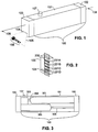
- Fig. 1 illustrates an isometric view of a hand-held laser pointer 100 for displaying holographic images in accordance with the principles of the present invention.
- the illustrated laser pointer 100 includes a longitudinal housing 101 having a hollow cavity (shown in Fig. 3), a cap 102, a substrate housing 103 and a button switch 107.
- the cap 102 and the substrate housing 103 are coupled at opposite ends of the longitudinal housing 101.
- the cap 102 provides means for containing a removable power-supply enclosed within the hollow cavity of the longitudinal housing 101.
- a preferred power-supply is more fully discussed with reference to Fig. 3.
- a preferred laser pointer 100 is the OEM Diode Laser System PM package, which is available from Power Technologies, Inc., located at P.O.
- the substrate housing 103 includes an elongated aperture 104 through which an image beam 105 passes to display the holographic image 106.
- the image beam 105 is produced by illuminating a phase mask, or other substrate, having at least one phase grating.
- the phase grating is preferably illuminated using a coherent beam of radiation, such as a laser beam, which is discussed in detail with reference to Figs. 2 and 3.
- a laser beam more particularly defined, is a narrow beam of coherent, and nearly monochromatic, electromagnetic radiation.
- the button switch 107 extends perpendicularly through an aperture in the longitudinal housing 101 and may be selectively depressed for a time period during which the laser pointer 100 is caused to generate the laser beam.
- the button switch 107 functions as a latch, reversing and maintaining its state each time it is depressed.
- the button switch 107 has been utilized in the illustrated embodiment, any suitably arranged selectably energizing or switching may be readily used in addition to or substituted for the button switch 107.
- Fig. 2 illustrates an isometric view of the substrate housing 103 and a single substrate 200.
- the illustrated substrate 200 includes four phase gratings 201a to 201d, also referred to as beam-splitters. Each of the gratings 201 a-d is representative of a distinct wave disturbance associated with a select object, such as previously mentioned examples, arrow, hand, slogan, etc.
- the substrate 200 is preferably positioned vertically within the substrate housing 103 and capable of being slidably moved, downwardly and upwardly, to exchange the phase gratings 201a-d before the laser beam. In an alternate preferred embodiment, the substrate 200 is positioned horizontally and slidably moved from side to side.
- the substrate 200 is utilized to record and subsequently reconstruct the amplitude and phase distributions of the distinct wave disturbance representative of the select object.
- the amplitude and phase distributions of the wave disturbance are utilized in the optical formation of the select image.
- a single substrate 200 has been utilized herein, it should be realized that a plurality of substrates could be used wherein each substrate includes one or more individual phase gratings 201. Further, two or more of those substrates 200 may be overlapped such that the laser beam intersects portions of at least two phase gratings 201 on at least two substrates 200, to thereby generate the image beam 105.
- the gratings 201a-d is intersected by the laser beam in the illustrated embodiment, it is illuminated and the representative image 106 is produced.
- the preferred technique for deriving the image of the select object 106 and producing the phase mask 200 is more fully discussed with reference to Fig. 6.
- Fig. 3 illustrates a cross-sectional view of the hand-held laser pointer 100 illustrated in Fig. 1 taken along line 108.
- the longitudinal housing 101 similarly includes the cap 102, the substrate housing 103 and the button switch 107. Additionally, illustrated within the hollow cavity of the longitudinal housing 101 are a power-supply 301, switching circuitry 302 and a laser diode system 303.
- the power-supply 301 includes two AAA batteries (3V) positioned in series, although any suitably arranged power supply may be used in addition to or substituted for the AAA batteries.
- the switching circuitry 302 which is responsive to the depression of the button switch 107, is operable to control the supply of power to the laser diode system 303.
- the laser diode system 303 preferably is a model PM 10 (635-15), which is also available from Power Technologies, Inc., located at P.O. Box 191117, Little Rock, Arkansas 72219-1117, USA.
- the PM 10 laser diode supplies 15mw of power at 635 nm.
- the power-supply 301 includes both positive and negative terminals, and is coupled at its positive end with the switching circuitry 302 through contact 304, and at its negative end with the laser diode system 303 through conductive means (not shown) incident to the cap 102 and wiring 305.
- Fig. 4 illustrates an isometric view of an alternate embodiment of the hand-held laser pointer 100 illustrated in Fig. 1.
- the substrate housing 103 is a ferrule which includes a single substrate 200 having at least one grating 201 fixed thereto.
- the laser pointer 100 which has a pen-like shape, is simply inserted into the ferrule 103 and energized, thereby generating the image beam 105 to display the image of the select object 106.
- Utilization of the ferrule embodiment enables the user to quickly and conveniently switch, or alternate, among any number of available substrates 200 and gratings 201 positioned within other suitably arranged substrate housings 103.
- the ferrule 103 includes a plurality of phase gratings 201 on a single substrate 200, wherein the ferrule is rotatable relative to the laser pointer 100 such that two phase gratings 201 may be exchanged with respect to the laser beam.
- One or more such embodiments may utilize an off-center laser beam to illuminate the one or more desired phase gratings 201, alternate preferred embodiments for generating the off-center laser beam are discussed with reference to Figs. 5b and 5c.
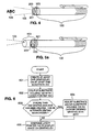
- Fig. 5a illustrates an isometric view of another alternate embodiment of the hand-held laser pointer 100 illustrated in Fig. 1.
- the laser pointer 100 again illustrated having a pen-like shape, is coupled with a cylindrical substrate housing 103 having a rotatable ring 501.
- a circular substrate 200 having one or more gratings 201 is positioned within the cylindrical housing 103 such that rotation of the ring 501 causes the phase gratings 201 to be moved past the laser beam to generate an off-center image beam 105.
- ring 501 has been utilized in this embodiment, any suitably arranged mechanical, electrical or electro-mechanical configuration for exchanging, interchanging, or overlapping a plurality of substrates 200 and/or a plurality of phase gratings 201 may be used in addition to or substituted for ring 501 and/or the substrate housing 103.
- Fig. 5b illustrates one embodiment for generating an off-center image beam 105 in accordance with the embodiment of the hand-held laser pointer illustrated in Fig. 5a.
- An off-center laser beam 500 is generated by positioning a pair of prisms 502 and 503 such that the generated laser beam 500 intersects and is reflected by prisms 502 and 503 causing the laser beam 500 to be stepped off-axis.
- the off-center laser beam 500 then intersects and illuminates one or more select phase gratings 201 on one or more circular substrates 200 in Fig. 5a to generate the off-center image beam 105.
- Fig. 5c illustrates an alternate embodiment for generating an off-center image beam 105 in accordance with the embodiment of the hand-held laser pointer illustrated in Fig. 5a.
- the off-center laser beam 500 is alternately generated by positioning a pair of mirrors 504 and 504 such that the generated laser beam 500 is reflected by the mirrors 504 and 505 to cause the laser beam 500 to be stepped off-axis.
- the off-center laser beam 500 then intersects and illuminates one or more select phase gratings 201 on one or more circular substrates 200 in Fig. 5a to generate the off-center image beam 105.
- Fig. 5d illustrates one embodiment of the rotating ring 501 in accordance with the embodiment of the hand-held laser pointer illustrated in Fig. 5a.
- the off-center laser beam 500 is illustrated as being stepped off-axis to intersect phase grating 201a fixed to circular substrate 200, which in Fig. 5a is located within cylindrical housing 103.
- a plurality of rotating rings 501 may be coupled with the laser pointer 100 such that one or more particular phase gratings 201 may be substituted for, exchanged with or overlapped with one another.
- Fig. 6 illustrates a flow diagram for assembling and using the hand-held laser pointer 100 and substrate 200 in accordance with the principles of the present invention.
- the phase gratings 201 are designed using scaler diffraction theory via a computer optimization process, block 601.
- the computer optimization process generates a data set representative of a desired phase grating 201, or beam array generator, to be fixed to the substrate 200.
- Fixed shall mean one or more of the following, but is not limited to, attached, imprinted, adhered, etched, mounted, inserted, scratched, or otherwise imaged or positioned.
- Phase gratings are desired in optical systems due to their higher diffraction efficiency.
- Diffractive phase gratings are more fully described in "Dammann Gratings for Laser Beam shaping," Optical Engineering, vol. 28, no. 12, pp. 1267-1275, Dec. 1989, by J. Jahns, M.M. Downs, M.E. Prise, N. Streibl, and S.J. Walker, which is incorporated herein by reference.
- the preferred optimization process is more fully described in copending and coassigned United States Patent Application Serial No. (Attorney Docket No. R.L.
- the data set is preferably utilized by conventional processes to generate an amplitude mask, to transfer the pattern resident to the amplitude mask to a photosensitive resist, and to preform reactive ion etching to generate a phase mask, the phase grating 201 and substrate 200 combination.
- the phase mask is then positioned within the substrate housing 103 which is then preferably coupled with laser pointer 100 at a laser beam generating end, block 602. If the embodiment under consideration includes a substrate 200 having more than one grating 201 and a second grating 201 is to be exchanged for or interchanged with a first grating 201, YES branch of decisional block 603, then, depending upon the current embodiment, either the substrate 200 or the substrate housing 103 is re-positioned such that the second grating 201 may be illuminated by the laser pointer 100, block 604.
- the second grating 201 may be resident to a second substrate 200, and it may be desirable to manipulate the first and second substrates 200 such that the second grating 201 is exchanged for, interchanged with, or overlaps the first grating 201 of the first substrate 200.
- the first and/or second substrates 200, and/or the substrate housing 103 will be repositioned such that the desired image is generated.
- the laser pointer 100 is selectively energized, such as by depressing button switch 107 in Figs. 1 and 3, to generate the desired image 106, block 605.
- Fig. 7 illustrates an artist's rendition of a phase grating 201 designed in accordance with the preferred computer optimization process for use with any of the hand-held laser pointers in Figs. 1 and 3-5.
- This phase grating 201 includes both light and dark areas representative of the surface heights on the underlying substrate 200. For example, assuming that the phase grating has been etched into the substrate, the light areas might represent the unetched portions, whereas the dark areas would represent the etched portions. If the substrate is glass, the preferable etching is approximately the wavelength of the laser which is .6 microns in the preferred embodiment, and the phase grating would be approximately a 1mm square or less and would be replicated many times over the substrate 200.
- FIG. 8 there is illustrated an artist's rendition of a holographic image generated utilizing any of the hand-held laser pointers 100 in Figs. 1 and 3-5 to illuminate the phase grating in Fig. 7.
Landscapes
- Physics & Mathematics (AREA)
- General Physics & Mathematics (AREA)
- Optics & Photonics (AREA)
- Holo Graphy (AREA)
- Overhead Projectors And Projection Screens (AREA)
- Diffracting Gratings Or Hologram Optical Elements (AREA)
Abstract
Disclosed are methods and apparatus for generating and displaying a select image (106) utilizing a hand-held device (100) operable to generate a coherent radiation beam and at least one phase mask (200). Each phase mask, having a first side and a second side, includes at least one phase grating (201) fixed thereto. One or more of the phase masks are positioned such that the generated coherent radiation beam from the hand-held device intersects the first side of one or more phase masks, illuminating at least a portion of at least one of the phase gratings to thereby generate an image beam (105) to display the select image (106).
Description
- The present invention is related to United States Patent Application Serial No. 08/312,858, Attorney Docket No. R.L. Morrison 4, entitled "Methods and Systems for Designing Beam Array Generators," commonly assigned to the assignee of the present invention, and filed concurrently herewith. The disclosure of this related Application is incorporated herein by reference.
- The present invention relates in general to laser technology and holography, and more particularly to methods and apparatus for generating and displaying holographic images utilizing a laser pointer.
- Conventional commercial laser pointers typically project a single, simple dot upon a targeted object, exhibit or image projected on a screen. The dot, which is generally quite small, can be utilized, for example, to pinpoint a particular area on the targeted object, to mark a particular word in a textual document projected on the screen, or to draw attention to a particular component in an exhibited diagram.
- The dot, is produced by generating a narrow beam of very bright light, either by firing brief pulses of light or by forming a continuous beam. The beam intersects the targeted object so that the dot, a sectional plane through the beam, is visually apparent. The dot is commercially available in only red or green. Laser light more particularly is coherent, meaning that all the rays of light have the same wavelength and are in phase, vibrating together to produce a single high-intensity light beam.
- Conventional pointers, however, are typically incapable of visual adjustment, as the generated dot can neither be reduced or enlarged in size, nor may it be focused. The beam produced dot is also limited functionally to either pinpointing or marking an area of interest. The dot is incapable of storing or conveying any information other than drawing a viewing audience's attention to a particular area of interest. Due to its size, which is typically smaller than a dime, the dot is difficult to view and perceive. The dot further fails to capture and hold the attention of the viewing audience for any extended period of time. Further, focusing one's attention upon the dot for a time period may cause an increasingly uncomfortable, and even painful, eye strain. This difficulty is compounded should the laser pointer be hand-held, as the user will generally be unable to hold or maintain the laser pointer in one fixed position causing the diminutive dot to bounce erratically.
- In accordance with the principles of the present invention which combine specially designed phase gratings with laser pointer technology, the projection of a select image is facilitated from a hand-held laser pointer, as opposed to merely projecting a single dot as in conventional laser pointers. The phase, or surface relief, gratings, which are also known as holograms, are generated in part utilizing a preferred computer optimization process. The select image may be, for example, as simple as an arrow or a pointing hand, or much more sophisticated, such as a slogan, phrase or corporate logo, or a picture, such as a face or a figure.
- An apparatus in accordance with the principles of the present invention for generating an image beam to display the select image includes a hand-held device operable to generate a coherent beam of radiation, and a phase mask.
The phase mask, which has both a first side and a second side, includes a phase grating, and is positioned such that the generated coherent beam of radiation intersects the first side of the phase mask, illuminating the phase grating to generate the image beam. - Another apparatus in accordance with the principles of the present invention for generating an image beam to display the select image includes a hand-held laser pointer, a substrate and a housing. The hand-held laser pointer is operable to generate and transmit a laser beam. The substrate includes at least one phase grating and is positioned within the housing so that the substrate is intersected by the transmitted laser beam. The transmitted laser beam thus intersects and illuminates the phase grating to generate the image beam.
- A method for generating an image beam to display a select image in accordance with the principles of the present invention concerns positioning a first substrate, which includes a first phase grating at a first location, generating a coherent radiation beam with a hand-held device, thereby illuminating the first phase grating with the generated coherent radiation beam to generate the image beam.
- For a more complete understanding of the present invention, and the advantages thereof, reference is made to the following descriptions taken in conjunction with the accompanying drawings in which like numbers designate like parts, and in which:
- Fig. 1 illustrates an isometric view of a hand-held laser pointer for displaying holographic images in accordance with the principles of the present invention;
- Fig. 2 illustrates an isometric view of a substrate housing illustrated in Fig. 1, and a single substrate which is to be positioned within the substrate housing;
- Fig. 3 illustrates a cross-sectional view of the hand-held laser pointer illustrated in Fig. 1;
- Fig. 4 illustrates an isometric view of an alternate embodiment of the hand-held laser pointer and substrate housing illustrated in Fig. 1;
- Fig. 5a illustrates an isometric view of another alternate embodiment of the hand-held laser pointer and substrate housing illustrated in Fig. 1;
- Fig. 5b illustrates one embodiment for generating an off-center image beam in accordance with the embodiment of the hand-held laser pointer illustrated in Fig. 5a;
- Fig. 5c illustrates another embodiment for generating an off-center image beam in accordance with the embodiment of the hand-held laser pointer illustrated in Fig. 5a;
- Fig. 5d illustrates one embodiment of a rotating ring in accordance with the embodiment of the hand-held laser pointer illustrated in Fig. 5a;
- Fig. 6 illustrates a flow diagram for assembling and using the hand-held laser pointer for displaying holographic images as illustrated in Fig. 1;
- Fig. 7 illustrates an artist's rendition of a phase grating designed in accordance with the principles of the present invention for use with any of the hand-held laser pointers in Figs. 1 and 3-5; and
- Fig. 8 illustrates an artist's rendition of a holographic image generated utilizing any of the hand-held laser pointers in Figs. 1 and 3-5 to illuminate the phase grating in Fig. 7.
- The principles of the present invention, and the features and advantages thereof, are better understood by referring to the illustrated embodiments depicted in Figs. 1-8 of the drawings.
- Fig. 1 illustrates an isometric view of a hand-held
laser pointer 100 for displaying holographic images in accordance with the principles of the present invention. The illustratedlaser pointer 100 includes alongitudinal housing 101 having a hollow cavity (shown in Fig. 3), acap 102, asubstrate housing 103 and abutton switch 107. Thecap 102 and thesubstrate housing 103 are coupled at opposite ends of thelongitudinal housing 101. Thecap 102 provides means for containing a removable power-supply enclosed within the hollow cavity of thelongitudinal housing 101. A preferred power-supply is more fully discussed with reference to Fig. 3. Apreferred laser pointer 100 is the OEM Diode Laser System PM package, which is available from Power Technologies, Inc., located at P.O. Box 191117, Little Rock, Arkansas 72219-1117, USA. Thesubstrate housing 103 includes anelongated aperture 104 through which animage beam 105 passes to display theholographic image 106. Theimage beam 105 is produced by illuminating a phase mask, or other substrate, having at least one phase grating. The phase grating is preferably illuminated using a coherent beam of radiation, such as a laser beam, which is discussed in detail with reference to Figs. 2 and 3. A laser beam, more particularly defined, is a narrow beam of coherent, and nearly monochromatic, electromagnetic radiation. Thebutton switch 107 extends perpendicularly through an aperture in thelongitudinal housing 101 and may be selectively depressed for a time period during which thelaser pointer 100 is caused to generate the laser beam. In an alternate embodiment, thebutton switch 107 functions as a latch, reversing and maintaining its state each time it is depressed. Although thebutton switch 107 has been utilized in the illustrated embodiment, any suitably arranged selectably energizing or switching may be readily used in addition to or substituted for thebutton switch 107. - Fig. 2 illustrates an isometric view of the
substrate housing 103 and asingle substrate 200. The illustratedsubstrate 200 includes fourphase gratings 201a to 201d, also referred to as beam-splitters. Each of thegratings 201 a-d is representative of a distinct wave disturbance associated with a select object, such as previously mentioned examples, arrow, hand, slogan, etc. Thesubstrate 200 is preferably positioned vertically within thesubstrate housing 103 and capable of being slidably moved, downwardly and upwardly, to exchange thephase gratings 201a-d before the laser beam. In an alternate preferred embodiment, thesubstrate 200 is positioned horizontally and slidably moved from side to side. Thesubstrate 200 is utilized to record and subsequently reconstruct the amplitude and phase distributions of the distinct wave disturbance representative of the select object. The amplitude and phase distributions of the wave disturbance are utilized in the optical formation of the select image. Although asingle substrate 200 has been utilized herein, it should be realized that a plurality of substrates could be used wherein each substrate includes one or moreindividual phase gratings 201. Further, two or more of thosesubstrates 200 may be overlapped such that the laser beam intersects portions of at least twophase gratings 201 on at least twosubstrates 200, to thereby generate theimage beam 105. When at least one of thegratings 201a-d is intersected by the laser beam in the illustrated embodiment, it is illuminated and therepresentative image 106 is produced. The preferred technique for deriving the image of theselect object 106 and producing thephase mask 200 is more fully discussed with reference to Fig. 6. - Fig. 3 illustrates a cross-sectional view of the hand-held
laser pointer 100 illustrated in Fig. 1 taken alongline 108. Thelongitudinal housing 101 similarly includes thecap 102, thesubstrate housing 103 and thebutton switch 107. Additionally, illustrated within the hollow cavity of thelongitudinal housing 101 are a power-supply 301, switchingcircuitry 302 and alaser diode system 303. In the illustrated embodiment, the power-supply 301 includes two AAA batteries (3V) positioned in series, although any suitably arranged power supply may be used in addition to or substituted for the AAA batteries. The switchingcircuitry 302, which is responsive to the depression of thebutton switch 107, is operable to control the supply of power to thelaser diode system 303. Thelaser diode system 303 preferably is a model PM 10 (635-15), which is also available from Power Technologies, Inc., located at P.O. Box 191117, Little Rock, Arkansas 72219-1117, USA. The PM 10 laser diode supplies 15mw of power at 635 nm. In the illustrated embodiment, the power-supply 301 includes both positive and negative terminals, and is coupled at its positive end with the switchingcircuitry 302 throughcontact 304, and at its negative end with thelaser diode system 303 through conductive means (not shown) incident to thecap 102 andwiring 305. - Fig. 4 illustrates an isometric view of an alternate embodiment of the hand-held
laser pointer 100 illustrated in Fig. 1. In this embodiment, thesubstrate housing 103 is a ferrule which includes asingle substrate 200 having at least onegrating 201 fixed thereto. Thelaser pointer 100, which has a pen-like shape, is simply inserted into theferrule 103 and energized, thereby generating theimage beam 105 to display the image of theselect object 106. Utilization of the ferrule embodiment enables the user to quickly and conveniently switch, or alternate, among any number ofavailable substrates 200 andgratings 201 positioned within other suitably arrangedsubstrate housings 103. In an alternate embodiment, theferrule 103 includes a plurality ofphase gratings 201 on asingle substrate 200, wherein the ferrule is rotatable relative to thelaser pointer 100 such that twophase gratings 201 may be exchanged with respect to the laser beam. One or more such embodiments may utilize an off-center laser beam to illuminate the one or more desiredphase gratings 201, alternate preferred embodiments for generating the off-center laser beam are discussed with reference to Figs. 5b and 5c. - Fig. 5a illustrates an isometric view of another alternate embodiment of the hand-held
laser pointer 100 illustrated in Fig. 1. In this embodiment, thelaser pointer 100, again illustrated having a pen-like shape, is coupled with acylindrical substrate housing 103 having arotatable ring 501. Acircular substrate 200 having one ormore gratings 201 is positioned within thecylindrical housing 103 such that rotation of thering 501 causes thephase gratings 201 to be moved past the laser beam to generate an off-center image beam 105. Althoughring 501 has been utilized in this embodiment, any suitably arranged mechanical, electrical or electro-mechanical configuration for exchanging, interchanging, or overlapping a plurality ofsubstrates 200 and/or a plurality ofphase gratings 201 may be used in addition to or substituted forring 501 and/or thesubstrate housing 103. - Fig. 5b illustrates one embodiment for generating an off-
center image beam 105 in accordance with the embodiment of the hand-held laser pointer illustrated in Fig. 5a. An off-center laser beam 500 is generated by positioning a pair ofprisms laser beam 500 intersects and is reflected byprisms laser beam 500 to be stepped off-axis. The off-center laser beam 500 then intersects and illuminates one or moreselect phase gratings 201 on one or morecircular substrates 200 in Fig. 5a to generate the off-center image beam 105. - Fig. 5c illustrates an alternate embodiment for generating an off-
center image beam 105 in accordance with the embodiment of the hand-held laser pointer illustrated in Fig. 5a. The off-center laser beam 500 is alternately generated by positioning a pair ofmirrors laser beam 500 is reflected by themirrors laser beam 500 to be stepped off-axis. The off-center laser beam 500 then intersects and illuminates one or moreselect phase gratings 201 on one or morecircular substrates 200 in Fig. 5a to generate the off-center image beam 105. - Fig. 5d illustrates one embodiment of the
rotating ring 501 in accordance with the embodiment of the hand-held laser pointer illustrated in Fig. 5a. The off-center laser beam 500 is illustrated as being stepped off-axis to intersect phase grating 201a fixed tocircular substrate 200, which in Fig. 5a is located withincylindrical housing 103. In an alternate embodiment, a plurality ofrotating rings 501 may be coupled with thelaser pointer 100 such that one or moreparticular phase gratings 201 may be substituted for, exchanged with or overlapped with one another. - Fig. 6 illustrates a flow diagram for assembling and using the hand-held
laser pointer 100 andsubstrate 200 in accordance with the principles of the present invention. Preferably, thephase gratings 201 are designed using scaler diffraction theory via a computer optimization process, block 601. The computer optimization process generates a data set representative of a desired phase grating 201, or beam array generator, to be fixed to thesubstrate 200. Fixed, as used herein, shall mean one or more of the following, but is not limited to, attached, imprinted, adhered, etched, mounted, inserted, scratched, or otherwise imaged or positioned. Phase gratings are desired in optical systems due to their higher diffraction efficiency. Diffractive phase gratings are more fully described in "Dammann Gratings for Laser Beam shaping," Optical Engineering, vol. 28, no. 12, pp. 1267-1275, Dec. 1989, by J. Jahns, M.M. Downs, M.E. Prise, N. Streibl, and S.J. Walker, which is incorporated herein by reference. The preferred optimization process is more fully described in copending and coassigned United States Patent Application Serial No. (Attorney Docket No. R.L. Morrison 4), entitled "Methods and Systems for Designing Beam Array Generators," and in the article, "A Selective Cell-based Algorithm for Designing High Efficiency Beam Array Generators," Diffractive Optics, vol. 1, pp. 76-79, OSA Technical Digest Series, 1994, by R.L. Morrison and M.J. Wojcik, which are both incorporated herein by reference. The data set is preferably utilized by conventional processes to generate an amplitude mask, to transfer the pattern resident to the amplitude mask to a photosensitive resist, and to preform reactive ion etching to generate a phase mask, the phase grating 201 andsubstrate 200 combination. - The phase mask is then positioned within the
substrate housing 103 which is then preferably coupled withlaser pointer 100 at a laser beam generating end, block 602. If the embodiment under consideration includes asubstrate 200 having more than onegrating 201 and asecond grating 201 is to be exchanged for or interchanged with afirst grating 201, YES branch ofdecisional block 603, then, depending upon the current embodiment, either thesubstrate 200 or thesubstrate housing 103 is re-positioned such that thesecond grating 201 may be illuminated by thelaser pointer 100, block 604. In an alternate embodiment, thesecond grating 201 may be resident to asecond substrate 200, and it may be desirable to manipulate the first andsecond substrates 200 such that thesecond grating 201 is exchanged for, interchanged with, or overlaps thefirst grating 201 of thefirst substrate 200. In such an embodiment, the first and/orsecond substrates 200, and/or thesubstrate housing 103 will be repositioned such that the desired image is generated. Thelaser pointer 100 is selectively energized, such as by depressingbutton switch 107 in Figs. 1 and 3, to generate the desiredimage 106, block 605. - Fig. 7 illustrates an artist's rendition of a phase grating 201 designed in accordance with the preferred computer optimization process for use with any of the hand-held laser pointers in Figs. 1 and 3-5. This phase grating 201 includes both light and dark areas representative of the surface heights on the
underlying substrate 200. For example, assuming that the phase grating has been etched into the substrate, the light areas might represent the unetched portions, whereas the dark areas would represent the etched portions. If the substrate is glass, the preferable etching is approximately the wavelength of the laser which is .6 microns in the preferred embodiment, and the phase grating would be approximately a 1mm square or less and would be replicated many times over thesubstrate 200. It should be noted that this illustration represents a two level hologram, and has been included herein for illustrative purposes only. Multi-level designs have higher diffraction efficiencies than the foregoing two-level phase grating, however, rigid submicron alignment tolerances must be maintained during the multi-step fabrication process of the multi-level designs to avoid potentially large fluctuations in beam array intensities. Two-level designs are therefore highly regarded, although multi-level designs are also well suited. Turning to Fig. 8, there is illustrated an artist's rendition of a holographic image generated utilizing any of the hand-heldlaser pointers 100 in Figs. 1 and 3-5 to illuminate the phase grating in Fig. 7. - Although the present invention and its advantages have been described in detail, it should be understood that various changes, substitutions and alterations can be made herein without departing from the spirit and scope of the invention.
Claims (36)
- An apparatus for generating an image beam to display a select image, said apparatus comprising:a hand-held device operable to generate a coherent beam of radiation; anda first phase mask having a first side and a second side, said phase mask positioned such that said generated coherent beam of radiation intersects said first side of said first phase mask to thereby generate said image beam.
- The apparatus as set forth in claim 1 further including means for selectively energizing said hand-held device to generate said coherent beam of radiation.
- The apparatus as set forth in claim 1 wherein the hand-held device further comprises a switch operable to generate selectively the coherent beam.
- The apparatus as set forth in claim 1 further comprising a housing coupled with said hand-held device wherein said first phase mask is positioned within said housing.
- The apparatus as set forth in claim 4 wherein said housing includes means for moving said first phase mask within said housing.
- The apparatus as set forth in claim 4 wherein said first phase mask is movable within said housing.
- The apparatus as set forth in claim 4 wherein said housing is removable from said hand-held device.
- The apparatus as set forth in claim 4 wherein said first phase mask includes a plurality of phase gratings, and further includes means for exchanging a second phase grating for a first phase grating.
- The apparatus as set forth in claim 8 wherein said exchanging means includes a rotating ring.
- The apparatus as set forth in claim 4 further comprising a second phase mask.
- The apparatus as set forth in claim 10 wherein said second phase mask is positioned within said housing such that at least a portion of each of said first phase mask and said second phase mask are intersected by the coherent beam of radiation to generate said image beam.
- An apparatus for generating an image beam to display a select image, comprising:a hand-held laser pointer operable to generate and transmit a laser beam having a beam output end and a housing coupled to said beam output end; anda first substrate including at least a first phase grating positioned in said housing so that said first phase grating is intersected by said transmitted laser beam to generate said image beam.
- The apparatus as set forth in claim 12 further including a switch operable to generate selectively said laser beam.
- The apparatus as set forth in claim 3 or 13 wherein said switch is a button switch.
- The apparatus as set forth in claim 13 wherein said switch further includes a latch having an ON state and an OFF state, said latch operable to reverse and maintain its state each time said switch is operated.
- The apparatus as set forth in claim 12 wherein said substrate includes a second phase grating and said housing further includes means for moving said substrate to position said second phase grating to be intersected by said laser beam to generate said image beam.
- The apparatus as set forth in claim 16 wherein said moving means translates said substrate between a first position corresponding to one of said first and second phase gratings intersecting said laser beam and a second position corresponding to the other of the first and second gratings intersecting said laser beam.
- The apparatus as set forth in claim 17 wherein said moving means performs linear translation.
- The apparatus as set forth in claim 17 wherein said moving means slides said substrate within said housing.
- The apparatus as set forth in claim 17 wherein said moving means performs rotatable translation.
- The apparatus as set forth in claim17 wherein said moving means includes a rotating ring.
- The apparatus as set forth in claim 12 wherein said housing is detachable from said beam output end.
- The apparatus as set forth in claim 7 or 12 wherein said housing is a ferrule.
- The apparatus as set forth in claim 12 wherein said substrate includes a second phase grating, and further includes means for exchanging said second phase grating for said first phase grating.
- The apparatus as set forth in claim 12 further comprising a second substrate including at least one phase grating.
- The apparatus as set forth in claim 25 wherein said second substrate includes a second phase grating, said apparatus further comprising means for overlapping said second substrate with said first substrate such that at least a portion of each of said first phase grating and said second phase grating are intersected by said transmitted laser beam whereby said transmitted laser beam illuminates at least a portion of said first phase grating and said second phase grating to generate said image beam.
- A method for generating an image beam to display a select image, said method comprising the steps of:positioning a first substrate including a first phase grating at a first location; andproducing a coherent radiation beam with a hand-held device, and illuminating said first phase grating with said produced coherent radiation beam to generate said image beam.
- The method as set forth in claim 24 wherein said hand-held device has an ON state and an OFF state and is operable during said ON state to produce a coherent radiation beam and during said OFF state to not produce a coherent radiation beam, and said producing step includes the step of switching from said OFF state to said ON state.
- The method as set forth in claim 27 wherein said producing step includes the step of depressing a switch, operating a latch having an active state and an inactive state, said latch operable to reverse and maintain its state each time said switch is depressed.
- The method as set forth in claim 27 wherein said first substrate includes a second phase grating, and said positioning step includes the step of moving said first substrate to position said second phase grating at said first location to be intersected by said coherent radiation beam, said coherent radiation beam intersecting and illuminating said second phase grating to generate said image beam.
- The method as set forth in claim 30 wherein said moving step includes the step of shifting linearly said first substrate.
- The method as set forth in claim 30 wherein said moving step includes the step of rotating said first substrate.
- The method as set forth in claim 32 wherein said rotating step further includes the step of turning a rotatable ring.
- The method as set forth in claim 27 wherein said first substrate is positioned in a substrate housing coupled with said hand-held device, and said positioning step includes the step of detaching the substrate housing from said hand-held device.
- The method as set forth in claim 27 wherein said first substrate includes a second phase grating, and further includes the step of exchanging said second phase grating for said first phase grating and producing said select image from said second phase grating.
- The method as set forth in claim 27 further including the step of overlapping a second substrate including a second phase grating with said first substrate such that at least a portion of each of said first phase grating and said second phase grating are intersected by said coherent radiation beam, said coherent radiation beam illuminating said portion of said first phase grating and said second phase grating to generate said image beam.
Applications Claiming Priority (2)
| Application Number | Priority Date | Filing Date | Title |
|---|---|---|---|
| US31285994A | 1994-09-27 | 1994-09-27 | |
| US312859 | 1994-09-27 |
Publications (2)
| Publication Number | Publication Date |
|---|---|
| EP0704721A2 true EP0704721A2 (en) | 1996-04-03 |
| EP0704721A3 EP0704721A3 (en) | 1997-12-17 |
Family
ID=23213335
Family Applications (1)
| Application Number | Title | Priority Date | Filing Date |
|---|---|---|---|
| EP95306627A Withdrawn EP0704721A3 (en) | 1994-09-27 | 1995-09-20 | Methods and apparatus for generating and displaying holographic images utilizing a laser pointer |
Country Status (2)
| Country | Link |
|---|---|
| EP (1) | EP0704721A3 (en) |
| JP (1) | JPH08115047A (en) |
Cited By (5)
| Publication number | Priority date | Publication date | Assignee | Title |
|---|---|---|---|---|
| WO1997050011A2 (en) * | 1996-06-25 | 1997-12-31 | Digital Optics Corporation | Diffractive optical elements and use thereof |
| US5938308A (en) * | 1996-06-25 | 1999-08-17 | Digital Opitcs Corporation | Projection pointer |
| US20100049283A1 (en) * | 2008-08-21 | 2010-02-25 | Bliss Holdings, Llc | Illumination-based medical device & methods of use thereof |
| EP2179767A1 (en) * | 2008-10-21 | 2010-04-28 | Yalong Trade, s.r.o. | The nasal applicator for intranasal blood irradiation with laser |
| CN104024920A (en) * | 2011-10-31 | 2014-09-03 | Lg伊诺特有限公司 | Light emitting module |
Families Citing this family (2)
| Publication number | Priority date | Publication date | Assignee | Title |
|---|---|---|---|---|
| JP2003014915A (en) * | 2001-07-03 | 2003-01-15 | Japan Science & Technology Corp | Optical element with dammann grating |
| NO323926B1 (en) * | 2004-11-12 | 2007-07-23 | New Index As | Visual system and control object and apparatus for use in the system. |
Citations (6)
| Publication number | Priority date | Publication date | Assignee | Title |
|---|---|---|---|---|
| EP0443817A1 (en) * | 1990-02-21 | 1991-08-28 | Texas Instruments Incorporated | Focussed light source pointer for three dimensional display |
| US5146463A (en) * | 1991-05-20 | 1992-09-08 | Spectra-Physics Scanning Systems, Inc. | Pointer beam for hand-held laser scanner |
| US5151800A (en) * | 1990-12-17 | 1992-09-29 | Environmental Research Institute Of Michigan | Compact hologram displays & method of making compact hologram |
| JPH06138424A (en) * | 1992-10-26 | 1994-05-20 | Seiko Epson Corp | Spatial optical modulator |
| US5328785A (en) * | 1992-02-10 | 1994-07-12 | Litel Instruments | High power phase masks for imaging systems |
| DE4309667A1 (en) * | 1993-03-26 | 1994-09-29 | Univ Dresden Tech | Optical system for two- and three-dimensional representation of information |
-
1995
- 1995-09-20 EP EP95306627A patent/EP0704721A3/en not_active Withdrawn
- 1995-09-27 JP JP27210095A patent/JPH08115047A/en active Pending
Patent Citations (6)
| Publication number | Priority date | Publication date | Assignee | Title |
|---|---|---|---|---|
| EP0443817A1 (en) * | 1990-02-21 | 1991-08-28 | Texas Instruments Incorporated | Focussed light source pointer for three dimensional display |
| US5151800A (en) * | 1990-12-17 | 1992-09-29 | Environmental Research Institute Of Michigan | Compact hologram displays & method of making compact hologram |
| US5146463A (en) * | 1991-05-20 | 1992-09-08 | Spectra-Physics Scanning Systems, Inc. | Pointer beam for hand-held laser scanner |
| US5328785A (en) * | 1992-02-10 | 1994-07-12 | Litel Instruments | High power phase masks for imaging systems |
| JPH06138424A (en) * | 1992-10-26 | 1994-05-20 | Seiko Epson Corp | Spatial optical modulator |
| DE4309667A1 (en) * | 1993-03-26 | 1994-09-29 | Univ Dresden Tech | Optical system for two- and three-dimensional representation of information |
Non-Patent Citations (1)
| Title |
|---|
| PATENT ABSTRACTS OF JAPAN vol. 18, no. 439 (P-1787) [6779] , 16 August 1994 & JP 06 138424 A (SEIKO EPSON CORP.), 20 May 1994, * |
Cited By (8)
| Publication number | Priority date | Publication date | Assignee | Title |
|---|---|---|---|---|
| WO1997050011A2 (en) * | 1996-06-25 | 1997-12-31 | Digital Optics Corporation | Diffractive optical elements and use thereof |
| WO1997050011A3 (en) * | 1996-06-25 | 1998-03-12 | Digital Optics Corp | Diffractive optical elements and use thereof |
| US5938308A (en) * | 1996-06-25 | 1999-08-17 | Digital Opitcs Corporation | Projection pointer |
| US6008941A (en) * | 1996-06-25 | 1999-12-28 | Digital Optics Corporation | Optical soft aperture and use thereof |
| US20100049283A1 (en) * | 2008-08-21 | 2010-02-25 | Bliss Holdings, Llc | Illumination-based medical device & methods of use thereof |
| EP2179767A1 (en) * | 2008-10-21 | 2010-04-28 | Yalong Trade, s.r.o. | The nasal applicator for intranasal blood irradiation with laser |
| CN104024920A (en) * | 2011-10-31 | 2014-09-03 | Lg伊诺特有限公司 | Light emitting module |
| US9279572B2 (en) | 2011-10-31 | 2016-03-08 | Lg Innotek Co., Ltd. | Light emitting module |
Also Published As
| Publication number | Publication date |
|---|---|
| JPH08115047A (en) | 1996-05-07 |
| EP0704721A3 (en) | 1997-12-17 |
Similar Documents
| Publication | Publication Date | Title |
|---|---|---|
| US10962787B1 (en) | Waveguide display device | |
| CA2271815C (en) | In-line holographic mask for micromachining | |
| US5718496A (en) | Projection pointer | |
| Sinzinger et al. | Microoptics | |
| EP1817655B1 (en) | Visual system | |
| US5633735A (en) | Use of fresnel zone plates for material processing | |
| US6018402A (en) | Apparatus and method for phase-encoding off-axis spatial light modulators within holographic data systems | |
| US20020071472A1 (en) | DOE-based systems and devices for producing laser beams having modified beam characteristics | |
| WO2002079874A1 (en) | Integrated laser diode array and applications | |
| US5570207A (en) | Holographic image identification system | |
| EP0704721A2 (en) | Methods and apparatus for generating and displaying holographic images utilizing a laser pointer | |
| EP0593265A1 (en) | Projection apparatus for holographic stereogram recording | |
| WO1997023859A3 (en) | Picture display device with two microlens arrays | |
| CA2329924C (en) | Diffusing imager and associated methods | |
| US4120559A (en) | Method of establishing secret information | |
| EP0926663B1 (en) | Reproduction of optical data | |
| US20020114076A1 (en) | DOE-based systems and devices for producing laser beams having modified beam characteristics | |
| US6771402B2 (en) | Method and apparatus for generating a hologram | |
| JPS6083916A (en) | Signal generator | |
| CN112004000A (en) | Light-emitting device and image acquisition device using same | |
| US20220381968A1 (en) | Device for projecting an image into the eye of a user | |
| CA2761126C (en) | In-line holographic mask for micromachining | |
| Wood et al. | Multimple-imaging and multiple-focusing Fresnel lenses with high numerical aperture | |
| JP2000507716A (en) | Systems related to light emission | |
| TW403939B (en) | The method and system to apply electric-type control general phase shift mask in the exposure of stepper |
Legal Events
| Date | Code | Title | Description |
|---|---|---|---|
| PUAI | Public reference made under article 153(3) epc to a published international application that has entered the european phase |
Free format text: ORIGINAL CODE: 0009012 |
|
| AK | Designated contracting states |
Kind code of ref document: A2 Designated state(s): DE FR GB IT |
|
| PUAL | Search report despatched |
Free format text: ORIGINAL CODE: 0009013 |
|
| STAA | Information on the status of an ep patent application or granted ep patent |
Free format text: STATUS: THE APPLICATION HAS BEEN WITHDRAWN |
|
| AK | Designated contracting states |
Kind code of ref document: A3 Designated state(s): DE FR GB IT |
|
| 18W | Application withdrawn |
Withdrawal date: 19971103 |