EP0704543A1 - Slide member made of sintered aluminum alloy and method of production thereof - Google Patents
Slide member made of sintered aluminum alloy and method of production thereof Download PDFInfo
- Publication number
- EP0704543A1 EP0704543A1 EP95915312A EP95915312A EP0704543A1 EP 0704543 A1 EP0704543 A1 EP 0704543A1 EP 95915312 A EP95915312 A EP 95915312A EP 95915312 A EP95915312 A EP 95915312A EP 0704543 A1 EP0704543 A1 EP 0704543A1
- Authority
- EP
- European Patent Office
- Prior art keywords
- aluminum alloy
- powder
- sintered
- slide member
- weight
- Prior art date
- Legal status (The legal status is an assumption and is not a legal conclusion. Google has not performed a legal analysis and makes no representation as to the accuracy of the status listed.)
- Granted
Links
Images


Classifications
-
- B—PERFORMING OPERATIONS; TRANSPORTING
- B22—CASTING; POWDER METALLURGY
- B22F—WORKING METALLIC POWDER; MANUFACTURE OF ARTICLES FROM METALLIC POWDER; MAKING METALLIC POWDER; APPARATUS OR DEVICES SPECIALLY ADAPTED FOR METALLIC POWDER
- B22F3/00—Manufacture of workpieces or articles from metallic powder characterised by the manner of compacting or sintering; Apparatus specially adapted therefor ; Presses and furnaces
- B22F3/12—Both compacting and sintering
- B22F3/16—Both compacting and sintering in successive or repeated steps
-
- C—CHEMISTRY; METALLURGY
- C22—METALLURGY; FERROUS OR NON-FERROUS ALLOYS; TREATMENT OF ALLOYS OR NON-FERROUS METALS
- C22C—ALLOYS
- C22C1/00—Making non-ferrous alloys
- C22C1/04—Making non-ferrous alloys by powder metallurgy
- C22C1/05—Mixtures of metal powder with non-metallic powder
-
- B—PERFORMING OPERATIONS; TRANSPORTING
- B22—CASTING; POWDER METALLURGY
- B22F—WORKING METALLIC POWDER; MANUFACTURE OF ARTICLES FROM METALLIC POWDER; MAKING METALLIC POWDER; APPARATUS OR DEVICES SPECIALLY ADAPTED FOR METALLIC POWDER
- B22F1/00—Metallic powder; Treatment of metallic powder, e.g. to facilitate working or to improve properties
- B22F1/16—Metallic particles coated with a non-metal
-
- B—PERFORMING OPERATIONS; TRANSPORTING
- B22—CASTING; POWDER METALLURGY
- B22F—WORKING METALLIC POWDER; MANUFACTURE OF ARTICLES FROM METALLIC POWDER; MAKING METALLIC POWDER; APPARATUS OR DEVICES SPECIALLY ADAPTED FOR METALLIC POWDER
- B22F3/00—Manufacture of workpieces or articles from metallic powder characterised by the manner of compacting or sintering; Apparatus specially adapted therefor ; Presses and furnaces
- B22F3/10—Sintering only
- B22F3/1003—Use of special medium during sintering, e.g. sintering aid
- B22F3/1007—Atmosphere
-
- B—PERFORMING OPERATIONS; TRANSPORTING
- B22—CASTING; POWDER METALLURGY
- B22F—WORKING METALLIC POWDER; MANUFACTURE OF ARTICLES FROM METALLIC POWDER; MAKING METALLIC POWDER; APPARATUS OR DEVICES SPECIALLY ADAPTED FOR METALLIC POWDER
- B22F3/00—Manufacture of workpieces or articles from metallic powder characterised by the manner of compacting or sintering; Apparatus specially adapted therefor ; Presses and furnaces
- B22F3/24—After-treatment of workpieces or articles
-
- C—CHEMISTRY; METALLURGY
- C22—METALLURGY; FERROUS OR NON-FERROUS ALLOYS; TREATMENT OF ALLOYS OR NON-FERROUS METALS
- C22C—ALLOYS
- C22C1/00—Making non-ferrous alloys
- C22C1/10—Alloys containing non-metals
-
- C—CHEMISTRY; METALLURGY
- C22—METALLURGY; FERROUS OR NON-FERROUS ALLOYS; TREATMENT OF ALLOYS OR NON-FERROUS METALS
- C22C—ALLOYS
- C22C32/00—Non-ferrous alloys containing at least 5% by weight but less than 50% by weight of oxides, carbides, borides, nitrides, silicides or other metal compounds, e.g. oxynitrides, sulfides, whether added as such or formed in situ
- C22C32/0047—Non-ferrous alloys containing at least 5% by weight but less than 50% by weight of oxides, carbides, borides, nitrides, silicides or other metal compounds, e.g. oxynitrides, sulfides, whether added as such or formed in situ with carbides, nitrides, borides or silicides as the main non-metallic constituents
- C22C32/0068—Non-ferrous alloys containing at least 5% by weight but less than 50% by weight of oxides, carbides, borides, nitrides, silicides or other metal compounds, e.g. oxynitrides, sulfides, whether added as such or formed in situ with carbides, nitrides, borides or silicides as the main non-metallic constituents only nitrides
-
- C—CHEMISTRY; METALLURGY
- C22—METALLURGY; FERROUS OR NON-FERROUS ALLOYS; TREATMENT OF ALLOYS OR NON-FERROUS METALS
- C22C—ALLOYS
- C22C32/00—Non-ferrous alloys containing at least 5% by weight but less than 50% by weight of oxides, carbides, borides, nitrides, silicides or other metal compounds, e.g. oxynitrides, sulfides, whether added as such or formed in situ
- C22C32/0089—Non-ferrous alloys containing at least 5% by weight but less than 50% by weight of oxides, carbides, borides, nitrides, silicides or other metal compounds, e.g. oxynitrides, sulfides, whether added as such or formed in situ with other, not previously mentioned inorganic compounds as the main non-metallic constituent, e.g. sulfides, glass
-
- F—MECHANICAL ENGINEERING; LIGHTING; HEATING; WEAPONS; BLASTING
- F16—ENGINEERING ELEMENTS AND UNITS; GENERAL MEASURES FOR PRODUCING AND MAINTAINING EFFECTIVE FUNCTIONING OF MACHINES OR INSTALLATIONS; THERMAL INSULATION IN GENERAL
- F16C—SHAFTS; FLEXIBLE SHAFTS; ELEMENTS OR CRANKSHAFT MECHANISMS; ROTARY BODIES OTHER THAN GEARING ELEMENTS; BEARINGS
- F16C33/00—Parts of bearings; Special methods for making bearings or parts thereof
- F16C33/02—Parts of sliding-contact bearings
- F16C33/04—Brasses; Bushes; Linings
- F16C33/06—Sliding surface mainly made of metal
- F16C33/12—Structural composition; Use of special materials or surface treatments, e.g. for rust-proofing
- F16C33/121—Use of special materials
-
- B—PERFORMING OPERATIONS; TRANSPORTING
- B22—CASTING; POWDER METALLURGY
- B22F—WORKING METALLIC POWDER; MANUFACTURE OF ARTICLES FROM METALLIC POWDER; MAKING METALLIC POWDER; APPARATUS OR DEVICES SPECIALLY ADAPTED FOR METALLIC POWDER
- B22F3/00—Manufacture of workpieces or articles from metallic powder characterised by the manner of compacting or sintering; Apparatus specially adapted therefor ; Presses and furnaces
- B22F3/24—After-treatment of workpieces or articles
- B22F2003/245—Making recesses, grooves etc on the surface by removing material
-
- B—PERFORMING OPERATIONS; TRANSPORTING
- B22—CASTING; POWDER METALLURGY
- B22F—WORKING METALLIC POWDER; MANUFACTURE OF ARTICLES FROM METALLIC POWDER; MAKING METALLIC POWDER; APPARATUS OR DEVICES SPECIALLY ADAPTED FOR METALLIC POWDER
- B22F2201/00—Treatment under specific atmosphere
- B22F2201/02—Nitrogen
-
- B—PERFORMING OPERATIONS; TRANSPORTING
- B22—CASTING; POWDER METALLURGY
- B22F—WORKING METALLIC POWDER; MANUFACTURE OF ARTICLES FROM METALLIC POWDER; MAKING METALLIC POWDER; APPARATUS OR DEVICES SPECIALLY ADAPTED FOR METALLIC POWDER
- B22F2998/00—Supplementary information concerning processes or compositions relating to powder metallurgy
- B22F2998/10—Processes characterised by the sequence of their steps
-
- B—PERFORMING OPERATIONS; TRANSPORTING
- B22—CASTING; POWDER METALLURGY
- B22F—WORKING METALLIC POWDER; MANUFACTURE OF ARTICLES FROM METALLIC POWDER; MAKING METALLIC POWDER; APPARATUS OR DEVICES SPECIALLY ADAPTED FOR METALLIC POWDER
- B22F2999/00—Aspects linked to processes or compositions used in powder metallurgy
Definitions
- the present invention relates to a slide member of a sintered aluminum alloy and a method of manufacturing the same, and more particularly, it relates to a slide member of a sintered aluminum alloy which has high strength ⁇ high hardness characteristics, and is further excellent in wear resistance and a method of manufacturing the same.
- slide members of sintered aluminum alloys there are typically parts for compressors such as a vane, a shoe and a side plate, and slide parts such as an oil pump rotor.
- slide members of a sintered aluminum alloy according to the present invention aluminum nitride films which are formed by a direct nitriding method are strongly bonded with an aluminum alloy matrix and dispersed, whereby the slide member exhibits excellent wear resistance and an excellent frictional sliding property. Therefore, no surface treatment such as Ni-P plating or ferrous thermal spraying is necessary.
- a ferrous material is employed for a part for a compressor or a part for an oil part.
- its weight comes into question.
- the ferrous material is employed for a member such as a vane or a rotor which slides at a variable speed ⁇ high speed
- inertial force ⁇ centrifugal force in acceleration ⁇ deceleration following sliding and rotation are increased in proportion to the mass.
- these forces are increased in proportion to the square of an angular speed of rotation.
- the overall appliance or apparatus In order to attain a high speed through a ferrous material, therefore, the overall appliance or apparatus must be increased in size and must be extremely strongly manufactured. In addition, there is such an apprehension that efficiency of the apparatus itself is reduced.
- Magnesium which is the lightest material, cannot attain matching with peripheral members since its thermal expansion coefficient is too large. Further, it cannot withstand employment as a slide member due to low hardness ⁇ low strength.
- the amounts of metal elements which can form fine intermetallic compounds by being bonded with aluminum are limited. Namely, the limit for the total amount of transition metal elements is about 4 weight %, in order to improve wear resistance without deteriorating strength ⁇ toughness in case of dispersing fine intermetallic compounds of an Fe, Ni or Fe-Ni aluminide. If the elements are added in excess of this amount, coarse crystallized substances or deposits are formed at the solidification rate of the fusion casting method, to deteriorate the strength.
- Japanese Patent Application No. 62-59684 Japanese Patent Laying-Open No. 1-132734
- "Aluminum Alloy for Vane Material” is known as a material for a vane of an aluminum alloy employing rapidly solidified aluminum alloy powder.
- a satisfactory result has not been attained also in the case of employing such rapidly solidified aluminum alloy powder.
- switching from the conventional flon medium to a substitutional flon medium represented by R134a is in progress. Consequently, frictional sliding environment between a vane and a cylinder case and between the vane and a rotor in the compressor is further strict due to reduction of the lubrication performance of a solvent. Consequently, abrasion damage and a seizure phenomenon readily take place in the powder aluminum alloy disclosed in Japanese Patent Application No. 62-59684, and further improvement has been awaited as a material for a vane.
- Japanese Patent Application No. 59-169016 Japanese Patent Publication No. 5-33298
- “Vane” discloses means of mixing 2 to 7 weight % of ceramic of SiC or Si3N4 of 5 to 50 ⁇ m in grain size into Al-Si alloy powder, solidifying this mixture and applying the same to a vane.
- Japanese Patent Application No. 1-290696 Japanese Patent Laying-Open No.
- Composite Vane for Compressor and Method of Manufacturing the Same discloses means of mixing 1 to 30 volume % of ceramic such as SiC, Al2O3, K2Pi4O2 or the like in the form of whiskers or grains to Al - 6 to 16 weight % Si alloy powder, solidifying the mixture and applying the same to a forward end portion of a vane.
- Japanese Patent Application No. 60-8894 Japanese Patent Publication No. 6-96188 "Fiber-Reinforced Metal Composite Material” discloses an aluminum alloy prepared by forming a matrix of a hyper-eutectic Al - 13 to 30 weight % Si alloy and making this matrix contain 5 to 15 volume % of alumina fiber or alumina-silica fiber of not more than 10 ⁇ m in mean diameter.
- Japanese Patent Application No. 4-280543 Japanese Patent Laying-Open No. 5-311302 "Low-Frictional Aluminum Alloy Excellent in High-Temperature Strength and Wear Resistance” discloses an aluminum alloy having a matrix of an Al - 10 to 25 weight % Si - 5 to 20 % Ni - 1 to 5 % Cu alloy, which is improved in wear resistance and seizure resistance by mixing ⁇ molding powder or whisker fiber of a nitride, a boride, an oxide, a carbide or the like to the same.
- Vane Type Compressor discloses means of forming an ion plating film of titanium nitride on a forward end portion of a vane which is made of an Al-Si alloy and forming an electric plating layer mainly composed of iron on its side surface.
- Japanese Patent Application No. 63-288508 Japanese Patent Laying-Open No. 2-136586
- Vane Type Compressor discloses means of providing a plating layer mainly composed of iron or nickel on a side surface of a vane of an aluminum alloy.
- Japanese Patent Application No. 62-186826 Japanese Patent Laying-Open No. 64-32087
- Vane Type Compressor discloses means of providing an electrolytic or electroless Ni-P plating layer on an outer surface of a vane which is made of an Al-Si alloy.
- Japanese Patent Application No. 3-82405 Japanese Patent Laying-Open No. 4-314868
- Slide Member discloses means of improving wear resistance and seizure resistance by forming an Ni-P plating or Ni-P/BN or SiC composite plating layer on a surface of a vane of an aluminum alloy.
- An object of the present invention is to provide a slide member of a sintered aluminum alloy which has high strength ⁇ high hardness characteristics, and is excellent in wear resistance.
- Another object of the present invention is to provide a method capable of manufacturing a slide member of a sintered aluminum alloy which has high strength ⁇ high hardness characteristics and is excellent in wear resistance without carrying out surface treatment such as Ni-P plating or thermal spraying efficiently with high economy.
- a slide member of a sintered aluminum alloy which is excellent in wear resistance and seizure resistance can be manufactured by a method which is excellent in economy without carrying out surface treatment, by making various experiments and studies.
- a slide member of a sintered aluminum alloy obtained according to the present invention can be sufficiently used as a vane for a rotary compressor which is employed under substitutional flon environment, for example, having more strict sliding conditions.
- the slide member of a sintered aluminum alloy according to the present invention is obtained by molding and sintering aluminum alloy powder, and includes a matrix of the aluminum alloy, and aluminum nitride films which are dispersed along old powder grain boundaries of this matrix. Assuming that such a state that the aluminum nitride films completely continuously enclose the peripheries of the old powder grain boundaries is at a dispersion ratio of 100 %, the aluminum nitride films are discontinuously dispersed at a dispersion ratio of not more than 80 %.
- the aluminum alloy powder is powder which is rapidly solidified at a solidification rate of at least 102°C/sec.
- the slide member is typically a vane material for a compressor.
- the thickness of the aluminum nitride films is not more than 2 ⁇ m. Assuming that the overall sintered aluminum alloy is 100 weight %, the content of the aluminum nitride films is at least 5 weight % and not more than 25 weight %.
- the matrix contains at least 10 weight % and not more than 30 weight % of Si, at least 2 weight % and not more than 6 weight % of Fe, at least 2 weight % and not more than 6 weight % of Ni, and at least 0.05 weight % of Mg, with the rest of Al and unavoidable impurities, assuming that the overall aluminum alloy matrix excluding the aluminum nitride films is 100 weight %.
- a relational expression of 15 % ⁇ W Si + W AlN ⁇ 50 % is satisfied assuming that the content of Si in the sintered aluminum alloy is W Si on the basis of weight and the content of aluminum nitride is W AlN on the basis of weight.
- the maximum grain size of Si crystals in the sintered aluminum alloy is not more than 15 ⁇ and the mean grain size is not more than 10 ⁇ m.
- the matrix of the aluminum alloy contains Fe and Ni.
- a relational expression of 0.8 ⁇ W Fe /W Ni ⁇ 1.25 is satisfied assuming that the content of Fe in the matrix is W Fe on the basis of weight and the content of Ni is W Ni on the basis of weight.
- spherical intermetallic compounds of Al9FeNi of not more than 5 ⁇ m in mean grain size are dispersed in the sintered aluminum alloy. More preferably, the sintered aluminum alloy has a true density ratio of at least 97 %, hardness (HR-A) of at least 55, transverse rupture strength of at least 600 MPa, and a thermal expansion coefficient of at least 12 x 10 ⁇ 6/°C.
- the slide member of a sintered aluminum alloy according to the present invention is characterized in the following fact. Namely, a sintered body in which aluminum nitride is dispersed and formed on the surface and the interior is formed by heating ⁇ holding a powder compact consisting of aluminum alloy powder which is rapidly solidified at a solidification rate of at least 102°C/sec., and this sintered body is solidified by hot forging or hot extrusion. Films of aluminum nitride are formed on surfaces of aluminum alloy grains by nitriding of the powder compact, whereby aluminum nitride is dispersed and present on the surface and in the interior of the sintered body upon formation of the sintered body.
- the hardness (HR-A) of the slide member of an aluminum alloy is at least 55, and transverse rupture strength is at least 600 MPa.
- the aluminum alloy powder contains 3 to 40 weight % of Si, and the maximum grain size of Si crystals in the sintered body is not more than 15 ⁇ m, and the mean grain size is not more than 10 ⁇ m.
- the aluminum alloy powder contains 2 to 7.5 weight % of Fe and 2 to 7.5 weight % of Ni.
- spherical intermetallic compounds of Al9FeNi of not more than 5 ⁇ m in mean grain size are dispersed and present.
- a method of manufacturing a slide member of a sintered aluminum alloy according to the present invention comprises a step of forming a powder compact by pressure-molding rapidly solidified aluminum alloy powder, a step of facilitating reaction between aluminum and nitrogen through an exothermic phenomenon following deposition of elements which are solidly dissolved in the aluminum alloy by heating ⁇ holding the powder compact in a nitrogen gas atmosphere for forming aluminum nitride on surfaces of the aluminum alloy powder grains, and a step of solidifying the sintered body by hot forging or hot extrusion.
- the aluminum alloy powder employed as a starting material is powder which is rapidly solidified at a solidification rate of at least 102°C/sec.
- the step of forming aluminum nitride on the surfaces of the aluminum alloy powder grains and the step of sintering the powder compact progress at the same time.
- components of the aluminum alloy powder employed as the starting material are expressed in a general formula Al-a ⁇ Fe-b ⁇ Ni, and composition weight ratios thereof satisfy a: 2 to 7.5 %, b: 2 to 7.5 %, rest: Al and unavoidable impurities, and 0.8 ⁇ a/b ⁇ 1.25.
- components of the aluminum alloy powder employed as the starting material are expressed in a general formula Al-a ⁇ Si-b ⁇ Fe-c ⁇ Ni, and composition weight ratios thereof satisfy a: 3 to 40 %, b: 2 to 7.5 %, c: 2 to 7.5 %, rest: Al and unavoidable impurities, and 0.8 ⁇ b/c ⁇ 1.25.
- At least one element selected from a group consisting of Cr, Ti, Mo, Zr and V is added into the aluminum alloy powder in a range of not more than 5 % on the basis of weight.
- At least one element selected from a group consisting of C, BN, MoS2 and CaF2 is added into the aluminum alloy powder in a range of not more than 5 % on the basis of weight.
- Cu is added in a range of 0.4 to 8.0 % on the basis of weight
- Mg is added in a range of 0.5 to 1.5 % on the basis of weight into the sintered aluminum alloy powder.
- the aluminum alloy powder employed as the starting material has fluidity satisfying conditions of not more than 60 seconds/50 g in an orifice tube of 4 mm ⁇ .
- the step of forming a powder compact includes a step of solidifying the aluminum alloy powder to be 50 % to 80 % in true density ratio by cold stamp molding.
- the aluminum nitride forming step and the step of sintering the powder compact include steps of heating ⁇ holding the powder compact in nitrogen gas atmospheres of temperatures of 500°C to 570°C for at least 30 minutes.
- the solidification step by hot forging or hot extrusion includes a step of making the true density ratio of the sintered body at least 97 %.
- the method further comprises a step of heating the sintered body to 400°C to 500°C in advance of the solidification step by hot forging or hot extrusion.
- the method comprises a step of performing solution heat treatment on the sintered body at a temperature of 300°C to 500°C for 0.5 to 4 hours after the solidification step by hot forging or hot extrusion.
- the method preferably comprises a step of carrying out aging treatment on the sintered body at not more than 200°C after the solution heat treatment step.
- the method comprises a step of forming a groove on a pressurized surface of the sintered body in case of solidifying the sintered body by hot forging.
- the sectional shape of the groove is preferably a V shape.
- the method further comprises a step of rupturing the sintered body along the groove by applying a shearing load or a bending load onto the pressurized surface of the solidified said sintered body.
- the step of forming aluminum nitride films on the surfaces of the aluminum alloy powder grains and the step of sintering the powder compact are simultaneously carried out in a nitrogen atmosphere which is controlled in a temperature range of 500 to 570°C, so that aluminum nitride films of at least 5 % and not more than 25 % on the basis of weight are discontinuously dispersed along the old powder grain boundaries in the aluminum alloy sintered body.
- the true density ratio of the sintered body after hot forging or hot extrusion is at least 97 %.
- components of the aluminum alloy powder employed as the starting material are expressed in a general formula Al-a ⁇ Si-b ⁇ Fe-c ⁇ Ni-d ⁇ Mg, and composition weight ratios thereof satisfy a: 10 to 30 %, b: 2 to 6 %, c: 2 to 6 %, d: at least 0.05 %, rest: Al and unavoidable impurities, and 0.8 ⁇ b/c ⁇ 1.25.
- a slide member of a sintered aluminum alloy obtained according to the present invention has excellent wear resistance, and can be applied to a frictional sliding part.
- a vane for a rotary compressor, which is one of frictional sliding parts, used under strict sliding conditions is illustratively picked up, to give an outline up to the present invention.
- the following problem is caused: Namely, mechanical characteristics of the aluminum alloy are reduced since bondability at the interfaces between the ceramic dispersed in the old powder grain boundaries and the aluminum matrix is weak. Further, the thermal expansion coefficient of the aluminum alloy is reduced and difference in thermal expansion coefficient between a rotor member or a cylinder case member forming the compressor and the vane material is increased, to induce efficiency reduction of the compressor caused by the difference in thermal expansion coefficient in high-temperature driving in the vicinity of 150°C as the result.
- the conventional hard grain dispersed type wear resistant aluminum alloy cannot satisfy wear resistance, further cannot satisfy mechanical characteristics required as a vane material, and further cannot solve the problem caused by the difference in thermal expansion coefficient.
- the inventors have sought after the possibility of forming AlN films on the powder grain surfaces by direct reaction of nitrogen gas (N) and aluminum (Al) not by adding ⁇ mixing AlN powder into the aluminum alloy powder but by heating the aluminum alloy powder in a nitrogen gas atmosphere in view of suppressing falling of the hard phases in sliding.
- N nitrogen gas
- Al aluminum
- the inventors have established a method of forming AlN films on surfaces of aluminum alloy powder grains by direct reaction between Al and nitrogen gas and finally homogeneously dispersing AlN in an aluminum alloy sintered body.
- the feature of the present invention resides in that rapidly solidified aluminum alloy powder is employed as raw material powder.
- the aluminum alloy powder is rapidly solidified at a solidification rate of at least 102°C/sec.
- impurity oxygen (O) contained in the nitrogen gas atmosphere, or oxygen in aluminum oxide films on the powder grain surfaces broken by heat generation is bonded with AlN in a process of formation of AlN by nitriding reaction, to form AlN (AlON) containing oxygen.
- AlN containing impurity oxygen is formed in the sintered body, heat conductivity of the sintered aluminum alloy is so reduced that frictional heat in driving readily fills up the vane as the result, and softens the material to cause strength reduction. Further, mismatching at the interfaces between the AlN films and the matrix is so caused that the AlN films fall from the matrix in sliding as the result.
- an extremely small amount of Mg contained in the aluminum alloy powder Namely, an extremely small amount of Mg of about 0.05 weight % is preferably contained in the aluminum alloy powder in the present invention. Then, Mg is preferentially reacted with oxygen (O), and inhibits such reaction that oxygen is bonded with AlN to form AlON in the process of formation of AlN.
- a preferred embodiment of the present invention is characterized in that AlN containing no oxygen is formed by containing an extremely small amount of Mg.
- a slide member consisting of an AlN dispersed aluminum alloy is manufactured in the following manner: Rapidly solidified aluminum alloy powder and solid lubricant components which are added at need are homogeneously mixed with each other and a green compact having porosity of 20 to 50 % is prepared by stamping ⁇ molding of this mixed powder.
- a green compact having porosity of 20 to 50 % is prepared by stamping ⁇ molding of this mixed powder.
- this green compact is thereafter heated ⁇ held in a nitrogen gas atmosphere which is maintained in a temperature area of 500 to 570°C, AlN films of 3 to 40 weight % are formed along old powder grain boundaries of the sintered body in a discontinuously dispersed manner simultaneously with sintering of the green compact.
- a sintered body in which aluminum nitride films are discontinuously dispersed along old powder grain boundaries is again heated at 400°C to 500°C. Thereafter a region of an aluminum alloy in a matrix is plastically deformed in this sintered body by hot forging thereby closing holes in the sintered body and solidifying the same to be at least 97 % in true density ratio for improving strength of the sintered aluminum alloy.
- the sintered aluminum alloy of the present invention it is possible to improve mechanical characteristics at the normal temperature and in a temperature area of about 150°C by conventional heat treatment (T4 treatment or T6 treatment etc., for example) by adding a proper amount of Cu.
- the feature of the present invention resides in that aluminum and nitrogen gas are reacted with each other to form and disperse aluminum nitride (AlN) in a sintered aluminum alloy.
- AlN aluminum nitride
- some experiments and studies have heretofore been made. While the outline of the conventional methods is described below, there are problems in all these conventional methods in points of productivity ⁇ economy, and those obtained by the methods are improper in performance as slide members such as vanes.
- an oxide coating of the aluminum alloy powder of the raw material suppresses nitriding reaction on the powder grain surfaces, and hence extreme reduction of 0.05 weight % is required in relation to the oxygen content of Al powder described in this prior art. Consequently, a specific oxidation suppression mechanism is required in steps of preparing the powder. Therefore, the cost for the raw material powder is increased as the result, to cause a problem in economy.
- the inventors have made various experiments and analyses, in order to solve the aforementioned problems. As the result, they have discovered a method of forming AlN by nitriding reaction while requiring neither a high temperature sintering process exceeding 1000°C nor employment of low oxygen containing aluminum powder and fine powder. This method utilizes a mechanism which is absolutely different from reduction ⁇ breaking effects for oxide coatings on powder grain surfaces by Mg.
- nitriding reaction a step wherein aluminum and nitrogen gas are reacted with each other to form AlN.
- a powder compact is sintered in a relatively low temperature area of 500 to 570°C.
- the inventors have noted an exothermic phenomenon caused when respective elements forcibly solidly dissolved in the powder matrix by rapid solidification are deposited, and discovered that the oxide coatings on the powder grain surfaces can be broken by utilizing this.
- Al + N ⁇ AlN hereinafter referred to as direct nitriding reaction
- direct nitriding reaction is facilitated between aluminum of the powder matrix and the nitrogen gas enclosing the same with no requirement for a catalyst.
- AlN films are formed along old powder grain boundaries of the aluminum sintered body.
- the inventors have made various experiments and analyses, whereby excellent wear resistance ⁇ seizure resistance and mechanical characteristics for serving as a vane material of a sintered aluminum alloy can be exhibited when Si crystals and AlN satisfying the expression (1) described below are dispersed in the sintered body. 10 % ⁇ W Si ⁇ 30 % (weight basis) (1) 15 % ⁇ W Si + W AlN ⁇ 60 % (weight basis) When the Si content is less than 10 weight %, or the total content of Si and AlN is less than 15 weight %, sufficient wear resistance and seizure resistance cannot be attained. Further, it is difficult to ensure hardness required as a vane material, at least 55 in HR-A hardness in more concrete terms.
- Fe and Ni have an effect of improving heat resistance and rigidity of the sintered aluminum alloy by forming fine metastable phases (non-equilibrium phases) with aluminum and being dispersed in the base. Namely, seizure with the counter material in sliding is remarkably suppressed by improving heat resistance, and hence addition of Fe and Ni is effective. Further, it is possible to suppress growth of Si crystals in heating ⁇ sintering by finely and homogeneously dispersing such thermally stable intermetallic compounds, thereby remarkably improving cuttability of the aluminum alloy as the result.
- the content of Fe contained in the matrix is in a range of 2 to 6 weight %, and the content of Ni is in a range of 2 to 6 weight %, assuming that the overall matrix of the sintered body consisting of aluminum alloy powder is 100 weight %. Further, it is preferable to satisfy a relational expression of 0.8 ⁇ W Fe /W Ni ⁇ 1.25 assuming that the content of Fe in the matrix is W Fe on the basis of weight and the content of Ni is W Ni on the basis of weight. With such contents of Fe and Ni, heat resistance of the sintered body is extremely improved.
- These high melting point metal elements are thermally stable and hard, and hence it is possible to improve heat resistance and hardness of the aluminum alloy when the same are homogeneously dispersed in the base in grain sizes of not more than 1 ⁇ m, preferably not more than 0.5 ⁇ m. Therefore, it is preferable to contain one or at least two elements selected from Cr, Ti, Mo, Zr and V in the rapidly solidified aluminum alloy powder in a range not exceeding 5 weight % in total, at need. If the total amount of addition exceeds 5 weight %, there arises a problem of strength reduction caused by conversion of the powder solidified body into a fragile state, and an atomization temperature in powder preparation steps is increased to also cause an economical problem of cost increase of the powder due to increase in power consumption in dissolution.
- the lubricant component When MoS2 is added, the lubricant component is thermally decomposed from around 300°C and reacted with O2 gas to form SO2 gas if oxygen gas is present in the sintering atmosphere, and hence MoS2 as a lubricant component is not sufficiently remained in the sintered body. If so, the aforementioned effect cannot be attained. Further, the SO2 gas shields the powder grain surfaces, and hence there also arises such a problem that the aforementioned direct nitriding reaction is suppressed and formation of AlN films is hindered. In order to avoid such problems, it is necessary to control oxygen concentration in the nitrogen gas atmosphere in case of adding MoS2.
- raw material powder is first supplied to a mold and formed into a shape which is in line with the final product shape, i.e., which is similar to the final product shape.
- economical effects such as improvement of the raw material yield and reduction of the working cost can be expected.
- flowability and chargeability with respect to the powder are required.
- the grain size of the powder is fine, fluidity of the powder to the mold particularly comes into question, and the amount of flowing of nitrogen gas differs in the interior of the compact since density distribution in the powder compact is heterogeneous.
- the amount of AlN formed ⁇ dispersed by direct nitriding reaction is heterogeneous in the interior of the sintered body, and hence the aforementioned wear resistance and seizure resistance cannot be ensured.
- the powder is hard to charge in mold corner portions, and hence there arises such a problem that corner portions of the powder compact are chipped if fluidity of the powder is inferior.
- fluidity of the powder is an important required characteristic in the slide member of an aluminum alloy according to the method of the present invention.
- the flow rate of the powder in an orifice 4 mm ⁇ is not more than 60 seconds/50 g, in order to make the slide member producible with no economical problem in mass production steps.
- the employed rapidly solidified aluminum alloy powder does not satisfy this condition, however, it is preferable to improve the fluidity in a state of sufficiently maintaining the degree of quenching and physical characteristics of the powder by mechanically granulating ⁇ mixing the powder.
- Fig. 3 shows an example of a method of manufacturing a slide member of a sintered aluminum alloy according to the present invention.
- the green compact In a green compact which is less than 50 % in true density ratio, on the other hand, the green compact lacks in handleability since strength thereof is small and productivity is extremely reduced by such a problem that chipping is caused in the green compact in a carriage process, although nitriding reaction homogeneously progresses in a short time. Therefore, the green compact is preferably 50 % to 80 % in true density ratio.
- Stamping ⁇ molding are preferably carried out in a temperature area where the temperature of the powder is the normal temperature, or in a temperature area where the temperature does not exceed 300°C. Atmosphere control is required for oxidation suppression if the temperature exceeds 300°C, while the characteristics of the aluminum alloy may be reduced if the temperature exceeds about 450°C, since the rapidly solidified structure of the powder may be broken depending on the heat treatment conditions.
- Objects of carrying out hot forging are to finely pulverize the AlN films which are formed on the old powder grain boundaries or the old powder grain surfaces in the first place, to attain improvement in strength and hardness of the sintered body by closing holes in the sintered body, diffusion-bonding metal (Al) parts with each other on interfaces thereof and solidifying the same to at least 97 % in true density ratio in the second place, and to provide a V-shaped groove in a pressurized surface of the powder solidified body in the third place.
- Al diffusion-bonding metal
- the aforementioned objects can be attained either by immediately solidifying the nitride green compact which is heated by sintering by hot forging or by re-heating a temporarily cooled sintered body to 400°C to 570°C and thereafter solidifying the same by hot forging.
- a temporarily cooled sintered body to 400°C to 570°C and thereafter solidifying the same by hot forging.
- an extremely high forging pressure is necessary for making plastic deformation since deformation resistance of the sintered body is large in heating of less than 400°C. Consequently, a problem of abrasion damage of the mold is caused or introduction of a large press is required, to reduce economy.
- With a re-heating temperature exceeding 500°C there arises necessity for controlling the heating atmosphere in view of prevention of oxidation of the sintered body in the heating process. In excess of 570°C, further, the characteristics of the sintered body are reduced since Si and deposits are coarsed.
- the re-heating temperature is preferably 400°C to 570°C
- Grooves which are formed in a pressurized surface of a forged solidified sintered aluminum alloy define recesses, whereby a powder solidified body can be readily ruptured along the grooves when a shearing load or a bending load is applied to the pressurized surface of the solidified sintered body. In this case, cracking of the rupture progresses substantially perpendicularly to a plate thickness direction. On the other hand, it has been recognized that no small cracking is caused.
- V-shaped grooves can be provided to a large powder solidified body through a single hot forging step by employing the aforementioned manufacturing method, and it is possible to manufacture two or more vane materials from one sintered body.
- the aim is to prepare products which are engaged along ruptured surfaces thereof after division, in the method of the prior art.
- that in the form of a rectangular parallellopiped having no grooves is employed for a preliminary powder compact, and V-shaped grooves are provided in the forging step after sintering for rupturing the final compact under a low load through this recess effect.
- grooves are formed in the preliminary compact and the grooves are temporarily closed in the forging step after sintering to rupture the final compact by employing insufficient bondability (tears) thereof as propagation paths of cracking.
- the method of the present invention and the method disclosed in Japanese Patent Laying-Open No. 1-272705 are different in object of the invention from each other, while there is extreme difference in steps of providing the grooves necessary for rupturing the final compacts and the methods thereof.
- the recess effect of the hot forged body is attained as the angles of forward ends of projections of a punch for providing the grooves are reduced.
- the forward angles of the projections are preferably at least 45°.
- the compact can be readily ruptured in an extremely short time as compared with a cutting work time for an extruded member, and [2] such an effect in an economical view that cutting margins of the material can be remarkably reduced in the present invention, as compared with the case of manufacturing an aluminum alloy part on the basis of the conventional hot extrusion method.
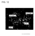
- Rapidly solidified aluminum alloy powder (43 ⁇ m in mean grain size) having a composition of Al - 4 Fe - 4 Ni - 1 Mg (weight basis) of 7 x 10²°C/sec. in degree of quenching was brought into a powder compact of 65 % in true density ratio by cold stamp molding.
- the dimensions of the powder compact were 10 x 30 x 10 mm.
- This powder compact was heated and held in an atmosphere which was fed with nitrogen gas (20 l/min.) under sintering conditions of 540°C x 30 minutes, and thereafter immediately worked into a powder solidified body of 100 % in true density ratio by hot forging (7 tons/cm in surface pressure).
- the dimensions of the powder solidified body were 11 x 31 x 5 mm.
- Fig. 12 shows a metallographic photograph with an optical microscope
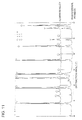
- Fig. 13 shows the results of analysis of raw material powder and its alloy by X-ray diffraction.
- Rapidly solidified aluminum alloy powder materials having the compositions shown in Table 3 were worked into powder compacts of 65 % in true density ratio by cold stamp molding.
- the dimensions of each powder compact were 15 x 40 x 10 mm.
- These powder compacts were heated and held in an atmosphere which was fed with nitrogen gas (20 l/min.) under sintering conditions of 540°C x 1 hour, and thereafter immediately worked into powder solidified bodies of 100 % in true density ratio by hot forging (6 tons/cm2 in surface pressure).
- the dimensions of the powder solidified bodies were 16 x 41 x 5 mm.
- the samples No. 20 and No. 21 were subjected to hot solidification under conditions described in Table 3.
- Table 4 shows characteristics of Si and AlN in aluminum alloys obtained in the aforementioned manner and material characteristics of the alloys.
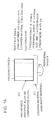
- Table 5 shows results of evaluation of wear resistance (counter material: A390 ingot aluminum alloy) of the alloys of the present invention and comparative alloys by an abrasion test method shown in Fig. 14.
- a ring member 20 consists of the inventive alloy or the comparative alloy, and a counter material 21 consists of an A390 ingot aluminum alloy. Pressing force P is applied to the ring member 20. The counter material 21 rotates at a peripheral speed V.
- Powder charging was not homogeneously performed in powder molding since flowability of the powder was inferior, whereby AlN formation amounts in the interior of the sintered body were varied with respective portions, and hence strength of the hot solidified alloy was reduced while breakage of the test piece in the abrasion test and chipping of respective portions of the vane material in compressor actual machine evaluation were recognized as the result.
- powder compacts consisting of the rapidly solidified aluminum alloy powder of the sample No. 7 in Table 3 were prepared.
- the dimensions of the powder compacts were 16 x 41 x 5 mm.
- Table 7 shows characteristics of Si and AlN in the aluminum alloys thus obtained and material characteristics of the alloys.
- Table 8 shows results of evaluation of wear resistance (counter material: A390 ingot aluminum alloy) of the inventive alloys and the comparative alloys by the abrasion test method shown in Fig. 14.
- each aluminum alloy was worked into the shape of a vane of 15 x 40 x 4 mm, and thereafter wear resistance and durability in relation to counter attackability were evaluated through the rotary compressor shown in Fig. 15 (cylinder part: A390 ingot aluminum alloy, rotor part: powder aluminum alloy of Al - 17 Si - 5 Fe - 4 Cu - 1 Mg composition).
- the test conditions were set at a rotational frequency of 5000 rpm and a test time of 100 hr. under an R134a substitutional flon atmosphere (15 atoms). Table 8 shows the results of the evaluation.
- the samples Nos. 1 to 12 are alloys according to the inventive manufacturing method, which had excellent mechanical characteristics and wear resistance and caused neither abrasion damage nor seizure in the durability evaluation test through the compressor actual machine but attained excellent results in wear resistance and counter attackability.
- the compact Since the true density ratio of the compact was small at 40 %, the compact had no sufficient compact strength but was broken during handling, and it was impossible to prepare a sample.
- AlN formed by direct nitriding reaction was not sufficiently obtained since the sintering temperature was low at 460°C, whereby wear resistance of the alloy was so reduced that seizure was caused on the vane forward end portion in the actual machine compressor evaluation as the result.
- Si crystals and intermetallic compounds dispersed in the base were coarsely grown since the sintering temperature was high at 600°C, whereby strength ⁇ toughness of the alloy were reduced to cause cracking of the sample in the abrasion test and breakage of the vane in actual machine compressor evaluation.
- AlN formed by direct nitriding reaction was not sufficiently obtained since the sintering time was short at 0.2 hours (12 minutes), whereby wear resistance of the alloy was so reduced that seizure was caused on the vane forward end portion in the actual machine compressor evaluation as the result.
- AlN formed in the sintered body was not finely dispersed and holes in the sintered body were not sufficiently closed since the forging surface pressure was low at 2 tons/cm2 in the hot forging process, whereby strength ⁇ toughness of the alloy were so reduced that cracking of the sample in the abrasion test and breakage of the vane in the actual machine compressor evaluation were caused as the result.
- AlN formed in the sintered body was not finely dispersed and holes in the sintered body were not sufficiently closed since the extrusion ratio was low at 4 in the hot extrusion process, whereby strength ⁇ toughness of the alloy were so reduced that cracking of the sample in the abrasion test and breakage of the vane in the actual machine compressor evaluation were caused as the result.
- Si crystals and intermetallic compounds dispersed in the base were coarsely grown since the heating temperature in case of re-heating the sintered body was high at 560°C, whereby strength ⁇ toughness of the alloy were so reduced that cracking of the sample in the abrasion test and breakage of the vane in the actual machine compressor evaluation were caused as the result.
- rapidly solidified aluminum alloy powder is employed as a starting material for homogeneously forming AlN in a powder compact by directly reacting Al of a base and nitrogen gas through an exothermic phenomenon thereof when the same heated in a nitrogen gas atmosphere after being stamped ⁇ molded. Further, it is possible to obtain a slide member of a sintered aluminum alloy which is excellent in wear resistance, seizure resistance and high temperature strength by solidifying this powder compact by hot forging working.
- a frictional coefficient ⁇ value in an abrasion test is 0.03 to 0.07, which is extremely low as compared with a conventional sliding material.
- Rapidly solidified aluminum alloy powder materials having the compositions shown in Table 9 were worked into powder compacts of 65 % in true density ratio by cold stamp molding.
- the dimensions of each powder compact were 95 in length x 40 in width x 10 mm in thickness.
- These powder compacts were heated and held in an atmosphere which was fed with nitrogen gas (20 l/min.) under sintering conditions of 540°C x 1 hour, and thereafter immediately worked into powder solidified bodies of 100 % in true density ratio by hot forging (7 tons/cm2 in surface pressure).
- the dimensions of the powder solidified bodies were 96 x 41 x 5 mm.
- a plurality of V-shaped projecting wedges each having a cross-directional length of 40 mm, a height of 2 mm and a forward end angle of 60° are provided on a pressurizing surface of an upper punch mold. These wedges are provided in six portions at intervals of 15 mm along the longitudinal direction. Therefore, V grooves of the same shapes of 40 mm in width are formed in a pressurized surface of each powder solidified body in hot forging. Then, each powder solidified body was ruptured by applying a shearing load to the pressurized surface, for continuously preparing six aluminum powder alloys having prescribed shapes (15 x 40 x 5 mm) from one base. However, the sample No. 20 was prepared by hot forging under the conditions described in Table 9.
- Table 10 shows characteristics of Si and AlN in the aluminum alloys obtained in the aforementioned manner and material characteristics of the alloys.
- Table 11 shows the results of evaluating wear resistance (counter material: A390 ingot aluminum alloy) of the inventive alloys and comparative alloys by the abrasion test method shown in Fig. 14.
- each aluminum alloy was worked into the shape of a vane of 15 x 40 x 4 mm, and thereafter wear resistance and durability in relation to counter attackability were evaluated through the rotary compressor shown in Fig. 15 (cylinder part: A390 ingot aluminum alloy, rotor part: powder aluminum alloy of Al - 17 Si - - Fe - 4 Cu - 1 Mg composition).
- the test conditions were set at a rotational frequency of 5000 rpm and a test time of 100 hr. under an R134a substitutional flon atmosphere (15 atoms). Table 11 shows the results of the evaluation.
- the powder compositions Nos. 1 to 12 are aluminum alloys obtained according to the manufacturing method of the present invention, had prescribed vane shapes (40 x 15 x 5 mm) with neither chipping of end portions in rupture steps nor presence of fine cracks, had excellent mechanical characteristics and wear resistance, caused neither abrasion damage nor seizure in the durability evaluation test through the compressor actual machine, and attained excellent results in wear resistance and counter attackability.
- Fine pulverization of AlN and closure of holes were not sufficient since the forging surface pressure in the hot forging process was not sufficient at 3 tons/cm2, whereby strength of the alloy was so reduced that breaking of the test piece in the abrasion test and chipping of respective portions of the vane material in the actual machine compressor evaluation were recognized as the result.
- the powder was not homogeneously charged in powder molding since flowability of the powder was inferior, whereby AlN formation amounts in the interior of the sintered body were varied with respective portions, and hence strength of the hot solidified alloy was reduced while breakage of the test piece in the abrasion test and chipping of respective portions of the vane material in compressor actual machine evaluation were recognized.
- the rapidly solidified aluminum alloy powder having the composition of the sample No. 7 in Table 9 was cold stamp molded, to prepare a powder compact of 65 % in true density ratio (the dimensions were 95 in length x 40 in width x 10 mm in thickness). Then, a powder solidified body was prepared by hot forging on this powder compact on the basis of the manufacturing conditions shown in Table 12, and then the powder solidified body was ruptured by applying a shearing load to the pressurized surface, for continuously preparing six aluminum powder alloys having prescribed shapes (15 x 40 x 5 mm) from one base.
- Table 13 shows characteristics of Si and AlN in the aluminum alloys thus obtained and material characteristics of the alloys.
- Table 14 shows the results of evaluating wear resistance (counter material: A390 ingot aluminum alloy) of the inventive alloys and comparative alloys by the abrasion test method shown in Fig. 14.
- each aluminum alloy was worked into the shape of a vane of 15 x 40 x 4 mm, and thereafter wear resistance and durability in relation to counter attackability were evaluated through the rotary compressor shown in Fig. 15 (cylinder part: A390 ingot aluminum alloy, rotor part: powder aluminum alloy of Al - 17 Si - 5 Fe - 4 Cu - 1 Mg composition).
- the test conditions were set at a rotational frequency of 5000 rpm and a test time of 100 hr. under an R134a substitutional flon atmosphere (15 atoms). Table 14 shows the results of the evaluation.
- V groove is a V-shaped groove having a depth of 2 mm and a forward end angle of 60°
- oblique V groove is an oblique V-shaped groove having a depth of 1.5 mm and a forward end angle of 45°.
- Samples Nos. 1 to 9 are aluminum alloys obtained by the manufacturing method of the present invention, had prescribed vane shapes (40 x 15 x 5 mm) with neither chipping of end portions in rupture steps nor presence of fine cracks, had excellent mechanical characteristics and wear resistance, caused neither abrasion damage nor seizure in the durability evaluation test through the compressor actual machine, and attained excellent results in wear resistance and counter attackability.
- the compact Since the true density ratio of the compact was small at 40 %, the compact had no sufficient compact strength but was broken during handling, and it was impossible to prepare a sample. Thus, no actual machine test evaluation was achieved.
- AlN formed by direct nitriding reaction was not sufficiently obtained since the sintering temperature was low at 460°C, whereby wear resistance of the alloy was so reduced that seizure was caused on the vane forward end portion in the actual machine compressor evaluation as the result.
- Si crystals and intermetallic compounds dispersed in the base were coarsely grown since the sintering temperature was high at 600°C, whereby strength ⁇ toughness of the alloy were reduced to cause cracking of the sample in the abrasion test and vane breakage in actual machine compressor evaluation as the result.
- AlN formed by direct nitriding reaction was not sufficiently obtained since the sintering time was short at 0.2 hours (12 minutes), whereby wear resistance of the alloy was so reduced that seizure was caused on the vane forward end portion in the actual machine compressor evaluation as the result.
- AlN formed in the sintered body was not finely dispersed and holes in the sintered body were not sufficiently closed since the forging surface pressure was low at 2 tons/cm2 in the hot forging process, whereby strength ⁇ toughness of the alloy were so reduced that cracking of the sample in the abrasion test and breakage of the vane in the actual machine compressor evaluation were caused as the result.
- Si crystals and intermetallic compounds dispersed in the base were coarsely grown since the heating temperature in case of re-heating the sintered body was high at 560°C, whereby strength ⁇ toughness of the alloy were so reduced that cracking of the sample in the abrasion test and breakage of the vane in the actual machine compressor evaluation were caused as the result.
- Rapidly solidified aluminum alloy powder (43 ⁇ m in mean grain size) having a composition of Al - 25 Si - 3.5 Fe - 3.5 Ni -0.1 Mg (weight % indication) of a solidification rate of 8 x 10²°C/sec. was stamp molded, to prepare a powder compact (dimensions: 10 x 30 x 10 mm) of 75 % in true density ratio.
- This powder compact was heated ⁇ held in an atmosphere which was fed with nitrogen (10 l/min.) under sintering conditions of 550°C x 60 minutes, and thereafter a sintered aluminum powder alloy of at least 97 % in true density ratio was immediately prepared by hot forging (8 tons/cm in surface pressure).
- Fig. 16 shows a metal structure photograph with an optical microscope.
- the photograph of Fig. 16 has a magnification of 1000.
- AlN films have a mean film thickness of about 1.1 ⁇ m, and are discontinuously formed ⁇ dispersed on old powder grain boundaries or old powder grain surfaces of the sintered aluminum alloy.
- the amount of formation of aluminum nitride films in this case is 13 weight %, and a dispersion ratio thereof is about 55 %.
- the maximum grain size of Si crystals dispersed in the matrix of the aluminum alloy is about 12 ⁇ m and the mean grain size is about 7 ⁇ m, while it is recognized that fine spherical intermetallic compounds of Al9FeNi having a mean grain size of about 2 ⁇ m are homogeneously dispersed in the alloy.
- Table 16 shows results of investigation as to Si grain sizes in the alloys, amounts of formation and film thicknesses of AlN films, and material characteristics (HR-A hardness ⁇ transverse rupture strength ⁇ thermal expansion coefficient).
- Granulating treatment was performed in order to improve flowability of the raw material powder, whereby the fluidity was extremely improved, and an excellent result was attained in actual machine evaluation with the compressor with no reduction of mechanical characteristics ⁇ frictional slidability of the sintered body.
- Powder compacts of 65 % in true density ratio were prepared by stamping ⁇ molding rapidly solidified aluminum alloy powder materials having the composition shown at No. 3 in Table 15. These powder compacts were heated ⁇ held in a nitrogen atmosphere (15 l/min. in gas flow rate) under conditions shown in Table 18, and thereafter hot forging was immediately performed to prepare sintered aluminum powder alloys of at least 97 % in true density ratio.
- the powder compositions Nos. 1 to 8 are aluminum alloys of the present invention, which have mechanical characteristics and thermal expansibility required for serving as vane materials. Further, neither abrasion damage nor seizure was caused also in durability ⁇ performance evaluation tests with a compressor actual machine and excellent results were attained in wear resistance and counter attackability, while no performance reduction of the compressor was recognized also in high temperature driving, but target performance (efficiency) was attained.
- Si crystals in the sintered body were so coarsed that sufficient transverse rupture strength for serving as a vane material was not attained since the sintering conditions were improper at 590°C x 1 hr, whereby the vane was broken in actual machine evaluation with the compressor as the result.
- Si crystals in the sintered body were coarsed while the amount of formation and film thicknesses of AlN films were so increased beyond proper ranges that sufficient transverse rupture strength for serving as a vane material was not attained since sintering conditions were improper at 600°C x 2 hr, whereby the vane was broken in actual machine evaluation with the compressor as the result. Further, a problem on performance as a vane material such that the thermal expansion coefficient was below 12 x 10 ⁇ 6/°C was caused since the total content of AlN coatings and Si crystals in the sintered body exceeded 50 weight %.
- the dispersion ratio of AlN coatings was increased to 92 % by long-time nitriding processing, whereby bondability between powder grains was inhibited, sufficient transverse rupture strength for serving as a vane material was not attained, and hence the vane was broken in actual machine evaluation with the compressor as the result. Further, a problem on performance as a vane material such that the thermal expansion coefficient was below 12 x 10 ⁇ 6/°C was caused since the total content of AlN coatings and Si crystals in the sintered body exceeded 50 weight %.
- Powder compacts of 70 % in true density ratio were prepared by stamping ⁇ molding rapidly solidified aluminum alloy powder having the composition shown at No. 4 in Table 15. These powder compacts were heated ⁇ held in a nitrogen atmosphere (flow rate: 15 l/min.) under conditions shown in Table 20, and thereafter hot forging was immediately performed to prepare sintered aluminum powder alloys. In the respective sintered aluminum alloys, results of investigation as to amounts of formation, film thicknesses and dispersion ratios of AlN films and material characteristics (HR-A hardness ⁇ transverse rupture strength ⁇ thermal expansion coefficient ⁇ true density ratio) are shown in Table 20.
- Samples Nos. 1 and 2 are aluminum alloys of the present invention, which have mechanical characteristics and thermal expansibility required as vane materials. Further, neither abrasion damage nor seizure was caused also in durability ⁇ performance evaluation tests with a compressor actual machine and excellent results were attained in wear resistance and counter attackability, while no performance reduction of the compressor was recognized also in high temperature driving, but target performance (efficiency) was attained.
- the thermal expansion coefficient was below 12 x 10 ⁇ 6/°C since the total content of AlN films and Si crystals in the sintered body exceeded 50 weight %, and the efficiency of the compressor was achievable to only 80 % of the target value.
- the true density ratio of the forged body was 90 % and sufficient hardness and transverse rupture strength for serving as a vane material were not attained, whereby the vane was broken in actual machine evaluation with a compressor as the result.
- a slide member of a sintered aluminum alloy obtained according to the present invention has high strength and high hardness, and is excellent in wear resistance.
- Typical usages of this slide member are sliding parts for compressors such as a vane, a shoe and a side plate, and a rotor for an oil pump.
- As other usages application to automobile parts such as a piston, a cylinder and a con'rod to which wear resistance slidability and heat resistance are required and household electric parts is possible.
Abstract
Description
- The present invention relates to a slide member of a sintered aluminum alloy and a method of manufacturing the same, and more particularly, it relates to a slide member of a sintered aluminum alloy which has high strength·high hardness characteristics, and is further excellent in wear resistance and a method of manufacturing the same.
- As slide members of sintered aluminum alloys, there are typically parts for compressors such as a vane, a shoe and a side plate, and slide parts such as an oil pump rotor. In the slide member of a sintered aluminum alloy according to the present invention, aluminum nitride films which are formed by a direct nitriding method are strongly bonded with an aluminum alloy matrix and dispersed, whereby the slide member exhibits excellent wear resistance and an excellent frictional sliding property. Therefore, no surface treatment such as Ni-P plating or ferrous thermal spraying is necessary.
- In general, a ferrous material is employed for a part for a compressor or a part for an oil part. In the case of the ferrous material, however, its weight comes into question. Particularly when the ferrous material is employed for a member such as a vane or a rotor which slides at a variable speed·high speed, inertial force·centrifugal force in acceleration·deceleration following sliding and rotation are increased in proportion to the mass. Further, these forces are increased in proportion to the square of an angular speed of rotation. In order to attain a high speed through a ferrous material, therefore, the overall appliance or apparatus must be increased in size and must be extremely strongly manufactured. In addition, there is such an apprehension that efficiency of the apparatus itself is reduced.
- Thus, a low specific gravity material has been watched with interest. Magnesium, which is the lightest material, cannot attain matching with peripheral members since its thermal expansion coefficient is too large. Further, it cannot withstand employment as a slide member due to low hardness·low strength.
- Then, employment of a lightweight aluminum alloy has been studied. In order to reduce thermal expansion and improve wear resistance in the aluminum alloy, means of adding mainly Si in a large amount has been attempted by various manufacturing methods.
- First, means of adding Si by an ingot technique such as fusion casting, fusion rolling, continuous casting or the like has been studied, while no satisfactory slide member has been obtained only by dispersion of Si primary crystals. Namely, it has been impossible to provide a slide member which can substitute for a ferrous material unless surface treatment such as hard alumite treatment or Ni-P plating is carried out. Particularly in the case of a vane for a compressor which is subjected to a high speed·a high load and used under a strict sliding condition such as a substitutional flon atmosphere, abrasion damage or seizure takes place. After all, it has been impossible to obtain a wear resistant slide member which can withstand strict environment even if Si is mainly added in a large amount by the ingot technique such as fusion casting, fusion rolling or continuous casting.
- Then, an attempt has been made to increase amounts of addition of alloy components of transition metal elements such as Fe, Ni, Cr and the like by improving the solidification rate of the fusion casting method. However, the amounts of metal elements which can form fine intermetallic compounds by being bonded with aluminum are limited. Namely, the limit for the total amount of transition metal elements is about 4 weight %, in order to improve wear resistance without deteriorating strength·toughness in case of dispersing fine intermetallic compounds of an Fe, Ni or Fe-Ni aluminide. If the elements are added in excess of this amount, coarse crystallized substances or deposits are formed at the solidification rate of the fusion casting method, to deteriorate the strength.
- When elements of Zr, Ti, Mo and V are added, a matrix is hardened by fine deposits and hence wear resistance can be further improved. When the fusion casting method is employed, however, reduction of the strength is caused if the total sum of the amounts of addition thereof exceeds 1 weight %. It is difficult to add the elements such as Fe, Ni, Mo, Ti, Zr, V and the like in practice due to a problem of segregation in the molten metal and the like, and it has been impossible to implement an aluminum alloy which is so excellent in wear resistance that the same can substitute for a ferrous material with no surface treatment, even if the same are added simultaneously with Si.
- In powder metallurgy, on the other hand, it is possible to obtain dispersion-strengthened alloy powder which is fine and has a homogeneous structure by adding the aforementioned transition metal elements in large amounts simultaneously with a large amount of Si by employing a rapid solidification method. If rapidly solidified aluminum alloy powder is employed as a raw material and solidified by powder metallurgy, enabled is preparation of a high silicon containing aluminum alloy or a high transition element containing aluminum alloy, which has been impossible to obtain in a fusion method. When fine crystallized substances and deposits thereof are homogeneously dispersed in a matrix, further, wear resistance is improved. It is known that the structure is further refined by increasing the solidification rate for the raw material powder and excellent characteristics are attained in this case.
- For example, Japanese Patent Application No. 62-59684 (Japanese Patent Laying-Open No. 1-132734) "Aluminum Alloy for Vane Material" is known as a material for a vane of an aluminum alloy employing rapidly solidified aluminum alloy powder. However, a satisfactory result has not been attained also in the case of employing such rapidly solidified aluminum alloy powder. In a present rotary compressor for a car air conditioner, switching from the conventional flon medium to a substitutional flon medium represented by R134a is in progress. Consequently, frictional sliding environment between a vane and a cylinder case and between the vane and a rotor in the compressor is further strict due to reduction of the lubrication performance of a solvent. Consequently, abrasion damage and a seizure phenomenon readily take place in the powder aluminum alloy disclosed in Japanese Patent Application No. 62-59684, and further improvement has been awaited as a material for a vane.
- As another method of improving wear resistance and seizure resistance of an aluminum alloy, development of a composite material dispersing hard grains such as ceramic or whisker short fiber in an aluminum alloy has been studied.
- In Japanese Utility Model Application No. 59-141396 (Japanese Utility Model Laying-Open No. 61-55188) "Vane for Rotary Compressor", for example, the following method has been proposed: SiC, Al₂O₃ and Si₃N₄ are selected as hard grains, and 3 to 30 volume % of these hard grains are added·mixed into Al-Si-Fe alloy powder, and a green compact is prepared by cold isostatic pressing (CIP). Thereafter the composite material is solidified by hot extrusion so that this composite material is positioned on a forward end portion of a vane which is under more strict frictional sliding conditions.
- Further, Japanese Patent Application No. 59-169016 (Japanese Patent Publication No. 5-33298) "Vane" discloses means of mixing 2 to 7 weight % of ceramic of SiC or Si₃N₄ of 5 to 50 µm in grain size into Al-Si alloy powder, solidifying this mixture and applying the same to a vane. Japanese Patent Application No. 1-290696 (Japanese Patent Laying-Open No. 3-151589) "Composite Vane for Compressor and Method of Manufacturing the Same" discloses means of mixing 1 to 30 volume % of ceramic such as SiC, Al₂O₃, K₂Pi₄O₂ or the like in the form of whiskers or grains to Al - 6 to 16 weight % Si alloy powder, solidifying the mixture and applying the same to a forward end portion of a vane.
- Further, Japanese Patent Application No. 60-8894 (Japanese Patent Publication No. 6-96188) "Fiber-Reinforced Metal Composite Material" discloses an aluminum alloy prepared by forming a matrix of a hyper-eutectic Al - 13 to 30 weight % Si alloy and making this matrix contain 5 to 15 volume % of alumina fiber or alumina-silica fiber of not more than 10 µm in mean diameter.
- Further, Japanese Patent Application No. 4-280543 (Japanese Patent Laying-Open No. 5-311302) "Low-Frictional Aluminum Alloy Excellent in High-Temperature Strength and Wear Resistance" discloses an aluminum alloy having a matrix of an Al - 10 to 25 weight % Si - 5 to 20 % Ni - 1 to 5 % Cu alloy, which is improved in wear resistance and seizure resistance by mixing·molding powder or whisker fiber of a nitride, a boride, an oxide, a carbide or the like to the same.
- In every ceramic dispersed aluminum alloy or fiber-reinforced aluminum alloy proposed in the aforementioned manner, however, abrasion damage and seizure of an A390 ingot aluminum alloy of a cylinder case member and an Al-Si-Fe powder alloy of a rotor material readily take place in evaluation of durability wear resistance under unprecedentedly severe substitutional flon environment, and further improvement has been demanded. The cause for this is conceivable as follows: The added ceramic is extremely hard and has an effect of remarkably improving heat resistance and hardness by being composed with the aluminum alloy. However, the hard ceramic is weak in adhesion in the interface between the same and the matrix, and hence the ceramic may fall from the matrix in sliding. In this case, the ceramic serves as an abrasive along the sliding surface and hence the vane of the ceramic dispersed aluminum alloy itself is readily worn while seizure to the counter material is readily caused by a new sliding surface. Further, it wears the counter material too.
- In the aforementioned method, further, there have been a problem of economy, a problem on production and the like since the high-priced ceramic is employed and the so-called two-layer structurization is made on the forward end portion and the plate type portion through different materials.
- To this end, development of a vane of an aluminum alloy in substitutional flon has been studied. As the result, a method of forming a hard plating layer or a plating layer containing a self-lubricant component on an outer peripheral portion of a vane and a method of forming an ion plating film consisting of a mixed phase of a metal and a nitride are employed at present in view of improving wear resistance and seizure resistance. For example, Japanese Patent Application No. 61-311256 (Japanese Patent Laying-Open No. 63-167092) "Vane Type Compressor" discloses means of forming an ion plating film of titanium nitride on a forward end portion of a vane which is made of an Al-Si alloy and forming an electric plating layer mainly composed of iron on its side surface. Japanese Patent Application No. 63-288508 (Japanese Patent Laying-Open No. 2-136586) "Vane Type Compressor" discloses means of providing a plating layer mainly composed of iron or nickel on a side surface of a vane of an aluminum alloy.
- Further, Japanese Patent Application No. 62-186826 (Japanese Patent Laying-Open No. 64-32087) "Vane Type Compressor" discloses means of providing an electrolytic or electroless Ni-P plating layer on an outer surface of a vane which is made of an Al-Si alloy. Japanese Patent Application No. 3-82405 (Japanese Patent Laying-Open No. 4-314868) "Slide Member" discloses means of improving wear resistance and seizure resistance by forming an Ni-P plating or Ni-P/BN or SiC composite plating layer on a surface of a vane of an aluminum alloy.
- When surface coating treatment is performed, however, it is necessary to first carry out rough working (primary working) of the surface of the vane material for ensuring dimensional accuracy for providing a surface treated coat. Then, it is necessary to carry out high-priced surface treatment (pretreatment, as the case may be). In a vane requiring further strict dimensional accuracy, finish working (secondary working) by polishing·grinding etc. is finally required. In the current method of manufacturing a vane of an aluminum alloy requiring a number of steps of primary working → pretreatment → surface treatment → secondary working for finishing a final product from the material of the aluminum alloy, therefore, omission of the surface treatment is the most important subject in view of economy. If the surface treated layer is separated during employment, the vane immediately loses its reliability, as a matter of course.
- An object of the present invention is to provide a slide member of a sintered aluminum alloy which has high strength·high hardness characteristics, and is excellent in wear resistance.
- Another object of the present invention is to provide a method capable of manufacturing a slide member of a sintered aluminum alloy which has high strength·high hardness characteristics and is excellent in wear resistance without carrying out surface treatment such as Ni-P plating or thermal spraying efficiently with high economy.
- The inventors have discovered that a slide member of a sintered aluminum alloy which is excellent in wear resistance and seizure resistance can be manufactured by a method which is excellent in economy without carrying out surface treatment, by making various experiments and studies. A slide member of a sintered aluminum alloy obtained according to the present invention can be sufficiently used as a vane for a rotary compressor which is employed under substitutional flon environment, for example, having more strict sliding conditions.
- In one aspect, the slide member of a sintered aluminum alloy according to the present invention is obtained by molding and sintering aluminum alloy powder, and includes a matrix of the aluminum alloy, and aluminum nitride films which are dispersed along old powder grain boundaries of this matrix. Assuming that such a state that the aluminum nitride films completely continuously enclose the peripheries of the old powder grain boundaries is at a dispersion ratio of 100 %, the aluminum nitride films are discontinuously dispersed at a dispersion ratio of not more than 80 %.
- Preferably, the aluminum alloy powder is powder which is rapidly solidified at a solidification rate of at least 10²°C/sec. Further, the slide member is typically a vane material for a compressor.
- Preferably, the thickness of the aluminum nitride films is not more than 2 µm. Assuming that the overall sintered aluminum alloy is 100 weight %, the content of the aluminum nitride films is at least 5 weight % and not more than 25 weight %.
- In a preferred embodiment, the matrix contains at least 10 weight % and not more than 30 weight % of Si, at least 2 weight % and not more than 6 weight % of Fe, at least 2 weight % and not more than 6 weight % of Ni, and at least 0.05 weight % of Mg, with the rest of Al and unavoidable impurities, assuming that the overall aluminum alloy matrix excluding the aluminum nitride films is 100 weight %.
- Preferably, a relational expression of 15 % ≦ WSi + WAlN ≦ 50 % is satisfied assuming that the content of Si in the sintered aluminum alloy is WSi on the basis of weight and the content of aluminum nitride is WAlN on the basis of weight. Preferably, the maximum grain size of Si crystals in the sintered aluminum alloy is not more than 15 µ and the mean grain size is not more than 10 µm.
- In the preferred embodiment, the matrix of the aluminum alloy contains Fe and Ni. A relational expression of 0.8 ≦ WFe/WNi ≦ 1.25 is satisfied assuming that the content of Fe in the matrix is WFe on the basis of weight and the content of Ni is WNi on the basis of weight.
- Preferably, spherical intermetallic compounds of Al₉FeNi of not more than 5 µm in mean grain size are dispersed in the sintered aluminum alloy. More preferably, the sintered aluminum alloy has a true density ratio of at least 97 %, hardness (HR-A) of at least 55, transverse rupture strength of at least 600 MPa, and a thermal expansion coefficient of at least 12 x 10⁻⁶/°C.
- In another aspect, the slide member of a sintered aluminum alloy according to the present invention is characterized in the following fact. Namely, a sintered body in which aluminum nitride is dispersed and formed on the surface and the interior is formed by heating·holding a powder compact consisting of aluminum alloy powder which is rapidly solidified at a solidification rate of at least 10²°C/sec., and this sintered body is solidified by hot forging or hot extrusion. Films of aluminum nitride are formed on surfaces of aluminum alloy grains by nitriding of the powder compact, whereby aluminum nitride is dispersed and present on the surface and in the interior of the sintered body upon formation of the sintered body.
- In a preferred embodiment, the hardness (HR-A) of the slide member of an aluminum alloy is at least 55, and transverse rupture strength is at least 600 MPa.
- In one embodiment, the aluminum alloy powder contains 3 to 40 weight % of Si, and the maximum grain size of Si crystals in the sintered body is not more than 15 µm, and the mean grain size is not more than 10 µm.
- In another embodiment, the aluminum alloy powder contains 2 to 7.5 weight % of Fe and 2 to 7.5 weight % of Ni. In the sintered body, spherical intermetallic compounds of Al₉FeNi of not more than 5 µm in mean grain size are dispersed and present.
- In one aspect, a method of manufacturing a slide member of a sintered aluminum alloy according to the present invention comprises a step of forming a powder compact by pressure-molding rapidly solidified aluminum alloy powder, a step of facilitating reaction between aluminum and nitrogen through an exothermic phenomenon following deposition of elements which are solidly dissolved in the aluminum alloy by heating·holding the powder compact in a nitrogen gas atmosphere for forming aluminum nitride on surfaces of the aluminum alloy powder grains, and a step of solidifying the sintered body by hot forging or hot extrusion.
- Preferably, the aluminum alloy powder employed as a starting material is powder which is rapidly solidified at a solidification rate of at least 10²°C/sec. In a preferred embodiment, the step of forming aluminum nitride on the surfaces of the aluminum alloy powder grains and the step of sintering the powder compact progress at the same time.
- In one embodiment, components of the aluminum alloy powder employed as the starting material are expressed in a general formula Al-a·Fe-b·Ni, and composition weight ratios thereof satisfy a: 2 to 7.5 %, b: 2 to 7.5 %, rest: Al and unavoidable impurities, and 0.8 ≦ a/b ≦ 1.25.
- In another embodiment, components of the aluminum alloy powder employed as the starting material are expressed in a general formula Al-a·Si-b·Fe-c·Ni, and composition weight ratios thereof satisfy a: 3 to 40 %, b: 2 to 7.5 %, c: 2 to 7.5 %, rest: Al and unavoidable impurities, and 0.8 ≦ b/c ≦ 1.25.
- In still another embodiment, at least one element selected from a group consisting of Cr, Ti, Mo, Zr and V is added into the aluminum alloy powder in a range of not more than 5 % on the basis of weight.
- In a further embodiment, at least one element selected from a group consisting of C, BN, MoS₂ and CaF₂ is added into the aluminum alloy powder in a range of not more than 5 % on the basis of weight.
- In a further embodiment, Cu is added in a range of 0.4 to 8.0 % on the basis of weight, and/or Mg is added in a range of 0.5 to 1.5 % on the basis of weight into the sintered aluminum alloy powder.
- In a further embodiment, the aluminum alloy powder employed as the starting material has fluidity satisfying conditions of not more than 60 seconds/50 g in an orifice tube of 4 mm⌀.
- In a further embodiment, the step of forming a powder compact includes a step of solidifying the aluminum alloy powder to be 50 % to 80 % in true density ratio by cold stamp molding. The aluminum nitride forming step and the step of sintering the powder compact include steps of heating·holding the powder compact in nitrogen gas atmospheres of temperatures of 500°C to 570°C for at least 30 minutes. The solidification step by hot forging or hot extrusion includes a step of making the true density ratio of the sintered body at least 97 %.
- In a further embodiment, the method further comprises a step of heating the sintered body to 400°C to 500°C in advance of the solidification step by hot forging or hot extrusion.
- In a further embodiment, the method comprises a step of performing solution heat treatment on the sintered body at a temperature of 300°C to 500°C for 0.5 to 4 hours after the solidification step by hot forging or hot extrusion. In this case, the method preferably comprises a step of carrying out aging treatment on the sintered body at not more than 200°C after the solution heat treatment step.
- In a further embodiment, the method comprises a step of forming a groove on a pressurized surface of the sintered body in case of solidifying the sintered body by hot forging. The sectional shape of the groove is preferably a V shape. More preferably, the method further comprises a step of rupturing the sintered body along the groove by applying a shearing load or a bending load onto the pressurized surface of the solidified said sintered body.
- Preferably, the step of forming aluminum nitride films on the surfaces of the aluminum alloy powder grains and the step of sintering the powder compact are simultaneously carried out in a nitrogen atmosphere which is controlled in a temperature range of 500 to 570°C, so that aluminum nitride films of at least 5 % and not more than 25 % on the basis of weight are discontinuously dispersed along the old powder grain boundaries in the aluminum alloy sintered body.
- The true density ratio of the sintered body after hot forging or hot extrusion is at least 97 %.
- In one embodiment, components of the aluminum alloy powder employed as the starting material are expressed in a general formula Al-a·Si-b·Fe-c·Ni-d·Mg, and composition weight ratios thereof satisfy a: 10 to 30 %, b: 2 to 6 %, c: 2 to 6 %, d: at least 0.05 %, rest: Al and unavoidable impurities, and 0.8 ≦ b/c ≦ 1.25.
-
- Fig. 1 is a diagram showing such a state that the dispersion ratio of aluminum nitride films is 100 %.
- Fig. 2 is a diagram showing such a state that the dispersion ratio of aluminum nitride films is not more than 80 %.
- Fig. 3 is a diagram showing an example of a manufacturing method according to the present invention.
- Fig. 4 is a diagram showing another example of a manufacturing method according to the present invention.
- Fig. 5 is a diagram illustratively showing a hot forging method of providing grooves.
- Fig. 6 shows photographs of sections of a powder-forged aluminum alloy having a V-shaped groove before and after rupture;
- Fig. 7 is a sectional photograph of a powder-forged aluminum alloy having a V-shaped groove after rupture;
- Fig. 8 is a metallographic photograph through an optical microscope.
- Fig. 9 is a diagram showing results of X-ray diffraction.
- Fig. 10 is a metallographic photograph through an optical microscope.
- Fig. 11 is a diagram showing results of X-ray diffraction.
- Fig. 12 is a metallographic photograph through an optical microscope.
- Fig. 13 is a diagram showing results of X-ray diffraction.
- Fig. 14 is a diagram showing an abrasion test method.
- Fig. 15 is a side elevational view of a compressor.
- Fig. 16 is a metallographic photograph through an optical microscope.
- A slide member of a sintered aluminum alloy obtained according to the present invention has excellent wear resistance, and can be applied to a frictional sliding part. A vane for a rotary compressor, which is one of frictional sliding parts, used under strict sliding conditions is illustratively picked up, to give an outline up to the present invention.
- When a vane material, for example, is formed by a conventional ceramic dispersed or fiber-reinforced aluminum alloy which is not subjected to surface treatment such as hard plating or thermal spraying and this is employed for a compressor in practice, the following problems are caused: Namely, in the first place, hard phases of ceramic grains or whisker fiber which are added·dispersed in an alloy matrix for improving wear resistance and seizure resistance fall in sliding, to abrasion-damage the vane material itself and the counter material.
- When, in the second place, the content of the ceramic which is added for improving wear resistance and seizure resistance is increased, the following problem is caused: Namely, mechanical characteristics of the aluminum alloy are reduced since bondability at the interfaces between the ceramic dispersed in the old powder grain boundaries and the aluminum matrix is weak. Further, the thermal expansion coefficient of the aluminum alloy is reduced and difference in thermal expansion coefficient between a rotor member or a cylinder case member forming the compressor and the vane material is increased, to induce efficiency reduction of the compressor caused by the difference in thermal expansion coefficient in high-temperature driving in the vicinity of 150°C as the result. Thus, the conventional hard grain dispersed type wear resistant aluminum alloy cannot satisfy wear resistance, further cannot satisfy mechanical characteristics required as a vane material, and further cannot solve the problem caused by the difference in thermal expansion coefficient.
- The inventors have made various types of abrasion tests for evaluating wear resistance, seizure resistance and attackability of aluminum alloys, and discovered that aluminum nitride (AlN) is proper as hard phases to be dispersed in an alloy matrix as the result. In the powder metallurgy of simply adding·mixing this AlN as grains or whisker fiber similarly to the conventional case, however, AlN falls from the matrix in sliding since adhesion in the interfaces between the matrix (Al) and AlN is weak as described above.
- Then, the inventors have sought after the possibility of forming AlN films on the powder grain surfaces by direct reaction of nitrogen gas (N) and aluminum (Al) not by adding·mixing AlN powder into the aluminum alloy powder but by heating the aluminum alloy powder in a nitrogen gas atmosphere in view of suppressing falling of the hard phases in sliding. As the result of energetically making experiments and studies, the inventors have established a method of forming AlN films on surfaces of aluminum alloy powder grains by direct reaction between Al and nitrogen gas and finally homogeneously dispersing AlN in an aluminum alloy sintered body.
- The feature of the present invention resides in that rapidly solidified aluminum alloy powder is employed as raw material powder. Preferably, the aluminum alloy powder is rapidly solidified at a solidification rate of at least 10²°C/sec.
- When aluminum alloy powder in which various types of elements are forcibly solidly dissolved in a matrix in a large amount by a rapid solidification method, an exothermic phenomenon is caused when the solidly dissolved elements are deposited. The inventors have noted this exothermic phenomenon. Namely, the inventors have discovered that it is possible to manifest·facilitate the aforementioned direct nitriding reaction

- The AlN films which are formed in the powder in the aforementioned method strongly adhere to Al of the matrix, and such a problem that AlN falls from the matrix in sliding is completely solved. Since the powder is heated in the relatively low temperature area (500 to 570°C) not coarsing the rapidly solidified structure, whereby a fine structure originally provided in the raw material powder can be maintained and a wear-resistant sintered aluminum alloy having both of high strength·high hardness characteristics can be obtained.
- In the aforementioned direct nitriding method, impurity oxygen (O) contained in the nitrogen gas atmosphere, or oxygen in aluminum oxide films on the powder grain surfaces broken by heat generation is bonded with AlN in a process of formation of AlN by nitriding reaction, to form AlN (AlON) containing oxygen. When such AlN containing impurity oxygen is formed in the sintered body, heat conductivity of the sintered aluminum alloy is so reduced that frictional heat in driving readily fills up the vane as the result, and softens the material to cause strength reduction. Further, mismatching at the interfaces between the AlN films and the matrix is so caused that the AlN films fall from the matrix in sliding as the result.
- With respect to such a problem, the inventors have discovered that it is effective to make an extremely small amount of Mg contained in the aluminum alloy powder. Namely, an extremely small amount of Mg of about 0.05 weight % is preferably contained in the aluminum alloy powder in the present invention. Then, Mg is preferentially reacted with oxygen (O), and inhibits such reaction that oxygen is bonded with AlN to form AlON in the process of formation of AlN. A preferred embodiment of the present invention is characterized in that AlN containing no oxygen is formed by containing an extremely small amount of Mg.
- A slide member consisting of an AlN dispersed aluminum alloy is manufactured in the following manner: Rapidly solidified aluminum alloy powder and solid lubricant components which are added at need are homogeneously mixed with each other and a green compact having porosity of 20 to 50 % is prepared by stamping·molding of this mixed powder. When this green compact is thereafter heated·held in a nitrogen gas atmosphere which is maintained in a temperature area of 500 to 570°C, AlN films of 3 to 40 weight % are formed along old powder grain boundaries of the sintered body in a discontinuously dispersed manner simultaneously with sintering of the green compact.
- In order to ensure mechanical characteristics as a vane material, the following method is effective: A sintered body in which aluminum nitride films are discontinuously dispersed along old powder grain boundaries is again heated at 400°C to 500°C. Thereafter a region of an aluminum alloy in a matrix is plastically deformed in this sintered body by hot forging thereby closing holes in the sintered body and solidifying the same to be at least 97 % in true density ratio for improving strength of the sintered aluminum alloy.
- In order to further improve productivity and economy in the method of manufacturing the vane material, preferably the green compact is solidified by hot forging immediately after the same is sintered in nitrogen gas. In such a method, the aforementioned re-heating step can be omitted. It is possible to reduce the nitriding treatment time by making the nitrogen gas atmosphere not a normal pressure but a pressurizing atmosphere, and improvement of economy is enabled.
- While it is possible to make the slide member of the sintered aluminum alloy exhibit target performance by hot extrusion, hot forging described later is more preferable in order to manufacture a vane material having a strip shape under more excellent productivity.
- In the sintered aluminum alloy of the present invention, it is possible to improve mechanical characteristics at the normal temperature and in a temperature area of about 150°C by conventional heat treatment (T4 treatment or T6 treatment etc., for example) by adding a proper amount of Cu.
- The feature of the present invention resides in that aluminum and nitrogen gas are reacted with each other to form and disperse aluminum nitride (AlN) in a sintered aluminum alloy. In relation to direct nitriding reaction, some experiments and studies have heretofore been made. While the outline of the conventional methods is described below, there are problems in all these conventional methods in points of productivity·economy, and those obtained by the methods are improper in performance as slide members such as vanes.
- "Synthesis of High Purity AlN by Nitridation of Li-Doped Al-Melt" (J. of the European Ceramic Society 6 (1990) 237 - 242) discloses that direct nitriding reaction of

- "Various Synthesizing Methods for Aluminum Nitride Powder" (Nihon Kinzoku Gakkai Kaiho Vol. 29, No. 7 (1990)) discloses a direct nitriding method of forming AlN by heating Al powder in nitrogen gas in a temperature area of 1150° to 1550°C. According to this method, however, high temperature sintering of 1150°C to 1550°C is necessary. When rapidly solidified aluminum alloy powder is employed, therefore, it is predicted that the fine structure of the powder is broken and becomes a coarse structure, and the characteristics of the alloy are extremely reduced. Further, an oxide coating of the aluminum alloy powder of the raw material suppresses nitriding reaction on the powder grain surfaces, and hence extreme reduction of 0.05 weight % is required in relation to the oxygen content of Al powder described in this prior art. Consequently, a specific oxidation suppression mechanism is required in steps of preparing the powder. Therefore, the cost for the raw material powder is increased as the result, to cause a problem in economy.
- In a method of preparing a sintered aluminum alloy disclosed in Japanese Patent Laying-Open No. 6-57363 "Nitrogen Compounded Aluminum Sintered Alloy and Method of Preparing the Same" or Japanese Patent Laying-Open No. 6-33164 "Method of Manufacturing Nitride Dispersed Al Alloy Member", aluminum alloy powder containing about 0.2 to 5 weight % of Mg as an essentially contained element is heated in a nitrogen gas atmosphere at 500 to 600°C. Due to this heating, AlN is formed on the powder grain surfaces by reaction between aluminum and nitrogen gas, and this is solidified thereby obtaining a sintered aluminum alloy in which AlN is dispersed. The feature of the preparation method disclosed in this prior art resides in that AlN is formed through a function of Mg reducing·breaking oxide coatings on the powder grain surfaces in sintering by containing Mg in the aluminum powder. This preparation method is absolutely different from the function·effect of Mg addition in the method of the present invention.
- While a solidification rate of at least 10²°C/sec. is required in relation to the raw material aluminum alloy powder which is disclosed in Japanese Patent Laying-Open No. 6-57363, this is aimed at solidifying a metastable phase in sintering and liquid-phase sintering the same. To this end, it is an effective method of forming the metastable phase in the powder to make the solidification rate at least 10²°C/sec. Therefore, this differs from the objects and the functional effect of the present invention.
- The inventors have made various experiments and analyses, in order to solve the aforementioned problems. As the result, they have discovered a method of forming AlN by nitriding reaction while requiring neither a high temperature sintering process exceeding 1000°C nor employment of low oxygen containing aluminum powder and fine powder. This method utilizes a mechanism which is absolutely different from reduction·breaking effects for oxide coatings on powder grain surfaces by Mg.
- Namely, direct nitriding reaction is facilitated in a relatively low sintering temperature area by utilizing a self exothermic phenomenon which is caused when rapidly solidified aluminum powder is heated, to form AlN films in a matrix. Such a method is absolutely different from conventional methods.
- It is said that strong oxide coatings are present on the surfaces of aluminum alloy powder grains and these oxide coatings inhibit nitriding reaction (a step wherein aluminum and nitrogen gas are reacted with each other to form AlN). According to the present invention, a powder compact is sintered in a relatively low temperature area of 500 to 570°C. At this time, the inventors have noted an exothermic phenomenon caused when respective elements forcibly solidly dissolved in the powder matrix by rapid solidification are deposited, and discovered that the oxide coatings on the powder grain surfaces can be broken by utilizing this. As the result,

- When raw material powder containing at least 0.05 weight % of Mg is employed assuming that the overall matrix of the sintered body is 100 weight %, it is possible to inhibit such reaction that oxygen is bonded with AlN to form AlON in the process of forming AlN, by preferentially reacting Mg and oxygen with each other. In particular, a range of 0.07 to 0.15 weight % is preferable as the content of Mg. If the Mg content is less than 0.05 weight %, there is a possibility that AlN (AlON) containing impurity oxygen is formed.
- In order to facilitate direct nitriding reaction through a self exothermic phenomenon, it is necessary to make the degree of quenching (solidification rate) for the rapidly solidified aluminum alloy powder which is raw material powder at least 10²°C/sec. The amount of elements which can be forcibly solidly dissolved in the matrix is small if the degree of quenching is less than 10²°C/sec., and hence a heating value which is sufficient for facilitating the direct nitriding reaction when the same are deposited by heating, and the aluminum oxide films covering the surfaces of the powder grains cannot be sufficiently broken. Consequently, the direct nitriding reaction does not sufficiently progress in the relatively low temperature area of 500 to 570°C, and a target amount of AlN cannot be formed.
- With respect to Al - 35 weight % Si rapidly solidified powder, for example, several types of samples whose degrees of quenching (solidification rates) were varied were prepared, molded to true density ratios of 65 % as to the respective types, and thereafter sintered in a nitrogen gas atmosphere at 540°C x 1 hr. Table 1 shows results of analysis of AlN amounts in these sintered bodies.
[Table 1] Degree of Quenching (°C/sec.) 5×10 7×10 1×10² 2×10² 7×10² 1×10³ 2×10³ AlN (wt.%) 0.1 0.7 8.3 16.6 22.4 27.2 35.4 - As obvious from Table 1, it is understood that a target amount of AlN cannot be formed when powder having a degree of quenching of less than 1 x 10²°C/sec. is employed.
- Preferably, the rapidly solidified aluminum alloy powder contains at least 0.05 weight % of Mg. If the Mg content is less than 0.05 weight %, oxygen which is present in the alloy cannot be completely fixed by reaction with Mg, and hence remaining oxygen is contained in AlN as an impurity. Consequently, there arise problems such as reduction of vane material strength caused by reduction in thermal conductivity of the sintered body and reduction of frictional slidability caused by mismatching of the AlN coatings and the matrix.
- It is possible to homogeneously form AlN layers containing no oxygen in the sintered body by controlling the solidification rate for the rapidly solidified aluminum alloy powder which is employed as raw material powder and an extremely small amount of Mg contained therein thereby facilitating direct nitriding reaction in a relatively low sintering temperature area of 500 to 570°C through a self exothermic phenomenon caused in sintering.
- The relation between solidification rates for rapidly solidified aluminum alloy powder containing a small amount of Mg and amounts of formation of AlN were investigated. In more concrete terms, Al - 40 weight % Si alloy powder (Mg content: 0.05 weight %) was employed to prepare several types of samples whose solidification rates were varied were prepared and molded to true density ratios of 70 % in relation to the respective types, and thereafter subjected to sintering in a nitrogen gas atmosphere at 540°C x 4 hr. Table 2 shows results of analysis of AlN formation amounts in the sintered bodies. As obvious from Table 2, it is understood that a target amount of AlN cannot be formed when aluminum alloy powder having a degree of quenching of less than 1 x 10²°C/sec. is employed.
[Table 2] Degree of Quenching (°C/sec.) 6x10 8x10 1x10² 2x10² 7x10² 1x10³ 2x10³ AlN (wt.%) 0.4 2.8 6.4 12.4 18.0 24.3 29.8 - AlN films formed by the direct nitriding method according to the present invention are discontinuously formed and dispersed along old powder grain boundaries or on old powder grain surfaces in the sintered aluminum alloy. Referring to Figs. 1 and 2,
reference numeral 1 denotes aluminum alloy powder grains, andreference numeral 2 denotes aluminum nitride films. Assuming that such a state that theAlN films 2 completely continuously enclose the peripheries of old powder grain boundaries of the aluminumalloy powder grains 1 as shown in Fig. 1 is at a dispersion ratio of 100 %, the AlN films are discontinuously formed and dispersed along old powder grain boundaries of the aluminumalloy powder grains 1 at a dispersion ratio of not more than 80 % in the sintered aluminum alloy of the present invention, as shown in Fig. 2. In regions where no AlN films are present, diffusion·sintering phenomenons between the aluminum alloy powder grains progress. - Preferably, the film thicknesses of the AlN films are not more than 2 µm. Preferably, the amount of formation of AlN is at least 5 weight % and not more than 25 weight %, assuming that the overall sintered aluminum alloy is 100 weight %.
- The reason for the aforementioned limitation as preferable ranges is now described. The AlN films improve wear resistance and seizure resistance of the sintered aluminum alloy, while the same may reduce mechanical characteristics to the contrary. Namely, the AlN films are formed on the old powder grain boundaries or the old powder grain surfaces, and hence there is such a possibility that the same inhibit bondability between the aluminum alloy powder grains and reduce the mechanical characteristics of the sintered body, depending on the amount of formation, the shapes or the dispersion ratio etc. of the AlN films.
- In more concrete terms, it has been confirmed that bondability between raw material powder grains is inhibited and strength for serving as a vane material (in more concrete terms, transverse rupture strength of at least 600 MPa) cannot be attained as the result when the thicknesses of the AlN films exceed 200 µm, or when the dispersion ratio of the AlN films covering the powder grain surfaces exceeds 80 %.
- The amount of formation of AlN is related to the total content with Si dispersed in the matrix described later. In order to ensure wear resistance·seizure resistance for serving as a vane material, however, at least 5 weight % of AlN is required. If the AlN formation amount is less than 5 weight %, wear resistance·seizure resistance for serving as a vane material cannot be sufficiently attained, and hence the vane material is abrasion-damaged or causes seizure with the counter material, to be incapable of withstanding practical use.
- As to the upper limit value of the AlN formation amount, 25 weight % is preferable due to restriction in mechanical characteristics and workability of the vane material. When the AlN formation amount exceeds 25 weight %, bondability between the raw material aluminum alloy powder grains is inhibited and the strength for serving as a vane material is reduced as the result, while there arises such a problem that chipping is caused in regions having weak bondability between the powder grains when a sample is worked.
- In order to satisfy all of wear resistance, seizure resistance, mechanical characteristics and workability for serving as a vane material, preferably the thicknesses of the AlN films are not more than 2 µm, the dispersion ratio of the AlN films is not more than 80 %, and the amount of formation of the AlN films is at least 5 weight % and not more than 25 weight %.
- It is possible to improve wear resistance and seizure resistance of the sintered body by homogeneously dispersing Si in the powder base, similarly to the AlN films. In order to sufficiently provide this effect, preferably it is desired to set sizes of Si crystals not more than 15 µm in maximum grain size while setting the mean grain size not more than 10 µm. When the maximum grain size of the Si crystals exceeds 15 µm, or the mean grain size exceeds 10 µm, there arises such a problem that the Si crystals attack the counter material in sliding, or breakage·falling of the Si crystals take place to cause seizure with the counter material. When coarse Si crystals are dispersed, further, it results in chipping (stress concentration) upon action of a load, to induce reduction in strength of the alloy.
- In relation to the content (WSi) of Si, Si which is present in the sintered body influences the mechanical characteristics, wear resistance·seizure resistance and the thermal expansibility of the sintered body. The Si content is closely related with the AlN formation amount (WAlN) in the sintered body. In order to employ the sintered aluminum alloy of the present invention as a vane material in practice, it is necessary to satisfy all of the aforementioned characteristics by optimizing the total content of Si and AlN.
- The inventors have made various experiments and analyses, whereby excellent wear resistance·seizure resistance and mechanical characteristics for serving as a vane material of a sintered aluminum alloy can be exhibited when Si crystals and AlN satisfying the expression (1) described below are dispersed in the sintered body.

- The thermal expansibility is now studied. When difference in thermal expansion coefficient between a rotor or a cylinder case and the vane material is increased, a clearance between the vane and the rotor or between the vane and the cylinder is increased in high-speed driving, and there arises a problem of reduction in performance of a compressor as the result. In such a point of view, the thermal expansion coefficient of the vane material is preferably at least 12 x 10⁻⁶/°C.
- Since elements greatly contributing to reduction of the thermal expansion coefficient are Si and AlN in the slide member of a sintered aluminum alloy, restriction is caused as to the upper limit value of the total content of these elements in view of the thermal expansion coefficient. In more concrete terms, it is necessary to satisfy the following expression (2), in order to ensure a thermal expansion coefficient of at least 12 x 10⁻⁶/°C which is required for the vane material:


- Fe and Ni have an effect of improving heat resistance and rigidity of the sintered aluminum alloy by forming fine metastable phases (non-equilibrium phases) with aluminum and being dispersed in the base. Namely, seizure with the counter material in sliding is remarkably suppressed by improving heat resistance, and hence addition of Fe and Ni is effective. Further, it is possible to suppress growth of Si crystals in heating·sintering by finely and homogeneously dispersing such thermally stable intermetallic compounds, thereby remarkably improving cuttability of the aluminum alloy as the result.
- According to the present invention, desirably the content of Fe contained in the matrix is in a range of 2 to 6 weight %, and the content of Ni is in a range of 2 to 6 weight %, assuming that the overall matrix of the sintered body consisting of aluminum alloy powder is 100 weight %. Further, it is preferable to satisfy a relational expression of 0.8 ≦ WFe/WNi ≦ 1.25 assuming that the content of Fe in the matrix is WFe on the basis of weight and the content of Ni is WNi on the basis of weight. With such contents of Fe and Ni, heat resistance of the sintered body is extremely improved.
- When rapidly solidified aluminum alloy powder having the aforementioned composition is prepared by an atomization method (a spraying method) and this green compact is sintered, spherical intermetallic compounds consisting of fine Al₉FeNi of not more than 5 µm in grain size are homogeneously dispersed in the matrix in the sintered body, whereby the sintered body has excellent heat resistance strength in a temperature range of 150 to 200°C as the result.
- When the content of either one or both of Fe and Ni is less than 2 weight %, or the content ratio (WFe/WNi) thereof is less than 0.8 or exceeds 1.25, the aforementioned intermetallic compounds of fine Al₉FeNi are not formed and hence it is difficult to attain excellent heat resistance strength. While Al-Ni and Al-Fe intermetallic compounds are also formed in the aforementioned preferable range, the inventors have also discovered that the effect by the intermetallic compounds of Al₉FeNi is by far superior to an effect of improvement of heat resistance by these dispersion effects.
- On the other hand, the effect related to heat resistance is not improved when either one or both of Fe and Ni are added in excess of 6 weight %, but the intermetallic compounds dispersed in the matrix are coarsed or brought into needle states on the contrary, and hence there arises such a problem that strength·toughness of the solidified sintered aluminum alloy are reduced.
- These high melting point metal elements are thermally stable and hard, and hence it is possible to improve heat resistance and hardness of the aluminum alloy when the same are homogeneously dispersed in the base in grain sizes of not more than 1 µm, preferably not more than 0.5 µm. Therefore, it is preferable to contain one or at least two elements selected from Cr, Ti, Mo, Zr and V in the rapidly solidified aluminum alloy powder in a range not exceeding 5 weight % in total, at need. If the total amount of addition exceeds 5 weight %, there arises a problem of strength reduction caused by conversion of the powder solidified body into a fragile state, and an atomization temperature in powder preparation steps is increased to also cause an economical problem of cost increase of the powder due to increase in power consumption in dissolution.
- When the aluminum alloy is used as a sliding part such as a vane or a pump rotor, it is important to ensure slidability (conformability) with a cylinder part or a pump case part in an initial stage of starting. To this end, means of adding these solid lubricants having effects as self-lubricant components in at least one or two in a range not exceeding 5 weight % at need is one of effective methods. The effect is not improved if the same are added in excess of 5 weight %, but there arises such a problem that the strength of the alloy is reduced, on the contrary.
- When MoS₂ is added, the lubricant component is thermally decomposed from around 300°C and reacted with O₂ gas to form SO₂ gas if oxygen gas is present in the sintering atmosphere, and hence MoS₂ as a lubricant component is not sufficiently remained in the sintered body. If so, the aforementioned effect cannot be attained. Further, the SO₂ gas shields the powder grain surfaces, and hence there also arises such a problem that the aforementioned direct nitriding reaction is suppressed and formation of AlN films is hindered. In order to avoid such problems, it is necessary to control oxygen concentration in the nitrogen gas atmosphere in case of adding MoS₂.
- When mechanical characteristics and corrosion resistance of the powder aluminum alloy are improved at need, it is effective to contain 4 to 8 weight % of Cu. In more concrete terms, it is possible to improve the mechanical characteristics by performing solution heat treatment at 300 to 500°C for 0.5 to 4 hr., or further performing aging treatment at not more than 200°C. The aforementioned functional effect is insufficient if the amount of addition of Cu is less than 0.4 weight %. If Cu exceeds 8 weight %, on the other hand, influence by a temperature in environment of use is readily exerted and heat resistance and hardness of the base are reduced.
- In the method according to the present invention, raw material powder is first supplied to a mold and formed into a shape which is in line with the final product shape, i.e., which is similar to the final product shape. Thus, economical effects such as improvement of the raw material yield and reduction of the working cost can be expected. In order to implement this, however, flowability and chargeability with respect to the powder are required. When the grain size of the powder is fine, fluidity of the powder to the mold particularly comes into question, and the amount of flowing of nitrogen gas differs in the interior of the compact since density distribution in the powder compact is heterogeneous. Consequently, the amount of AlN formed·dispersed by direct nitriding reaction is heterogeneous in the interior of the sintered body, and hence the aforementioned wear resistance and seizure resistance cannot be ensured. On the other hand, the powder is hard to charge in mold corner portions, and hence there arises such a problem that corner portions of the powder compact are chipped if fluidity of the powder is inferior. Thus, fluidity of the powder is an important required characteristic in the slide member of an aluminum alloy according to the method of the present invention.
- In more concrete terms, it is preferable to set flowability of the powder so that the flow rate of the powder in an orifice 4 mm⌀ is not more than 60 seconds/50 g, in order to make the slide member producible with no economical problem in mass production steps. When the employed rapidly solidified aluminum alloy powder does not satisfy this condition, however, it is preferable to improve the fluidity in a state of sufficiently maintaining the degree of quenching and physical characteristics of the powder by mechanically granulating·mixing the powder.
- Fig. 3 shows an example of a method of manufacturing a slide member of a sintered aluminum alloy according to the present invention.
- A green compact (powder compact) formed by molding raw material powder is prepared. This green compact is sintered in a nitrogen gas atmosphere, thereby forming AlN films on old powder grain boundaries or old powder grain surfaces in the sintered body in a discontinuously dispersed state. The green compact must be that of not more than 80 % in true density ratio, so that the nitrogen gas homogeneously flows into the interior of the green compact in the sintering process. If it exceeds 80 %, flowing of the nitrogen gas into the green compact is difficult, and hence it is difficult to homogeneously form the AlN films in a short time. In a green compact which is less than 50 % in true density ratio, on the other hand, the green compact lacks in handleability since strength thereof is small and productivity is extremely reduced by such a problem that chipping is caused in the green compact in a carriage process, although nitriding reaction homogeneously progresses in a short time. Therefore, the green compact is preferably 50 % to 80 % in true density ratio.
- Stamping·molding are preferably carried out in a temperature area where the temperature of the powder is the normal temperature, or in a temperature area where the temperature does not exceed 300°C. Atmosphere control is required for oxidation suppression if the temperature exceeds 300°C, while the characteristics of the aluminum alloy may be reduced if the temperature exceeds about 450°C, since the rapidly solidified structure of the powder may be broken depending on the heat treatment conditions.
- It is possible to form 3 to 40 weight % of AlN films in the sintered body by heating·sintering the green compact in a nitrogen gas atmosphere which is maintained at a temperature of 500°C to 570°C. As to the formation mechanism of the AlN films, the green compact is heated in a nitrogen gas atmosphere of 500°C to 570°C as described above, thereby facilitating direct nitriding reaction of aluminum of the powder base and nitrogen gas enclosing the same through exothermic reaction at the time when respective elements which are forcibly solidly dissolved in the powder base by rapid solidification are deposited, for forming the AlN films along the old powder grain boundaries in the sintered body in a discontinuously dispersed state as the result.
- In relation to the sintering temperature, a long-time sintering process exceeding about 20 hours is necessary for facilitating direct nitriding reaction of

- Then, the sintering time is studied. It has been possible to confirm formation of about 10 weight % of AlN films when heating·sintering were carried out for 5 minutes under a nitrogen gas atmosphere of 500°C to 570°C employing a relatively small green compact sample (a rectangular parallelopiped of 10 x 10 x 50 mm, for example) in a precedent experiment. However, temperature difference between the interior and a surface layer part is caused when the green compact is further increased, and hence heating of at least 30 minutes is necessary in order to homogeneously form AlN films in the sintered body. In order to form a target amount of AlN by direct nitriding reaction, therefore, sintering of at least 30 minutes is preferable.
- In relation to the used nitrogen gas, the manufacturing method of the present invention has absolutely no problem in economy since it is possible to sufficiently facilitate direct nitriding reaction even with nitrogen gas which is employed for industrial use in general.
- Objects of carrying out hot forging are to finely pulverize the AlN films which are formed on the old powder grain boundaries or the old powder grain surfaces in the first place, to attain improvement in strength and hardness of the sintered body by closing holes in the sintered body, diffusion-bonding metal (Al) parts with each other on interfaces thereof and solidifying the same to at least 97 % in true density ratio in the second place, and to provide a V-shaped groove in a pressurized surface of the powder solidified body in the third place.
- The aforementioned objects can be attained either by immediately solidifying the nitride green compact which is heated by sintering by hot forging or by re-heating a temporarily cooled sintered body to 400°C to 570°C and thereafter solidifying the same by hot forging. In the case of re-heating, however, an extremely high forging pressure is necessary for making plastic deformation since deformation resistance of the sintered body is large in heating of less than 400°C. Consequently, a problem of abrasion damage of the mold is caused or introduction of a large press is required, to reduce economy. With a re-heating temperature exceeding 500°C, there arises necessity for controlling the heating atmosphere in view of prevention of oxidation of the sintered body in the heating process. In excess of 570°C, further, the characteristics of the sintered body are reduced since Si and deposits are coarsed. From the above, the re-heating temperature is preferably 400°C to 570°C, particularly preferably 450°C to 500°C.
- Then, hot forging conditions are studied. It is possible to attain refinement pulverization of the aforementioned AlN films and increase of strength·increase of hardness of the sintered body by applying a forging pressure of at least 4 tons/cm² to the sintered body. Concrete characteristics which can be put into practice as a vane material are transverse rupture strength of at least 600 MPa and HR-A hardness of at least 55. Under a forging pressure of less than 4 tons/cm², the density of the sintered aluminum alloy is less than 97 % in true density ratio, and hence there arises such a problem that the vane material is readily influenced by the environment of usage due to bonding holes, in addition to the fact that sufficient strength·hardness for serving as the vane material cannot be attained as the result. Further, a target frictional slidability cannot be implemented since refinement pulverization of the AlN films is not sufficient.
- Fig. 4 shows another example of the manufacturing method according to the present invention. A point which is different from the method shown in Fig. 3 is that it comprises a rupture step after a solidification step by hot forging. In advance of this rupture, V-shaped grooves are provided in the pressurized surface of the sintered body in hot forging. This operation is described with reference to Fig. 5.
- First, in a stamping·molding step, rapidly solidified aluminum alloy powder 11 is pressure-molded by an
upper punch 12 and alower punch 13, to form apowder compact 14. In a sintering nitriding step, thepowder compact 14 is sintered. At the same time, aluminum nitride films are formed along old powder grain boundaries in the sintered body. In a hot forging step, thesintered body 15 is pressurized and solidified by anupper punch 16 and alower punch 17. In this solidification, grooves are formed in a pressurized surface of thesintered body 15. Theupper punch 16 haswedge portions 16a, for groove formation. Thus, V grooves 18a are formed in the surface of a forged solidifiedbody 18. A shearing load or a bending load is applied to the pressurized surface of the solidified sintered body, thereby rupturing the forged solidifiedbody 18 along the V grooves 18a, although this is not shown in Fig. 5. - Grooves which are formed in a pressurized surface of a forged solidified sintered aluminum alloy define recesses, whereby a powder solidified body can be readily ruptured along the grooves when a shearing load or a bending load is applied to the pressurized surface of the solidified sintered body. In this case, cracking of the rupture progresses substantially perpendicularly to a plate thickness direction. On the other hand, it has been recognized that no small cracking is caused.
- Fig. 6 shows sectional photographs before and after rupture of a powder forged aluminum alloy in which AlN is dispersed. As obvious from Fig. 6, it is possible to rupture a sintered body with a low load of about 40 kgf by having a V groove, and it is recognized that cracking thereof substantially perpendicularly progresses with respect to the pressurized surface of the aluminum alloy.
- Fig. 7 shows a sectional photograph of a powder forged aluminum alloy having no V groove after rupture. As obvious from Fig. 7, it has been recognized that cracking bently progresses in a test piece and a rupture load is extremely large at about 260 kgf when no V groove is provided.
- V-shaped grooves can be provided to a large powder solidified body through a single hot forging step by employing the aforementioned manufacturing method, and it is possible to manufacture two or more vane materials from one sintered body.
- Japanese Patent Laying-Open No. 1-272705 "Method of Preparing Powder Forged Part" discloses the following method of manufacturing a sintered part: Namely, a marking groove is provided in a preliminary powder compact, and exposed into the atmosphere after sintering before forging to form an oxide coating on the marking groove part. Then, this groove is closed in forging, but powder grains are not completely bonded with each other but remain as tears due to the presence of the oxide coating. A load is applied to this portion, thereby rupturing (separating) the compact along the tears.
- The method of the aforementioned prior art and the manufacturing method of the present invention are compared with each other. First, the object of the present invention is to efficiently prepare at least two final powder solidified bodies from a single solidified body by rupturing·dividing the same.
- On the other hand, the aim is to prepare products which are engaged along ruptured surfaces thereof after division, in the method of the prior art. In the present invention, further, that in the form of a rectangular paralellopiped having no grooves is employed for a preliminary powder compact, and V-shaped grooves are provided in the forging step after sintering for rupturing the final compact under a low load through this recess effect. In the method of the aforementioned prior art, on the other hand, grooves are formed in the preliminary compact and the grooves are temporarily closed in the forging step after sintering to rupture the final compact by employing insufficient bondability (tears) thereof as propagation paths of cracking.
- As hereinabove described, the method of the present invention and the method disclosed in Japanese Patent Laying-Open No. 1-272705 are different in object of the invention from each other, while there is extreme difference in steps of providing the grooves necessary for rupturing the final compacts and the methods thereof.
- When a powder aluminum alloy is prepared by the method of the present invention, there is no particular restriction in the shapes·sizes of the grooves which are provided in the pressurized surface of the powder solidified body. In relation to the angle of the grooves, it is possible to perpendicularly rupture the solidified body with no problem so far as the same is smaller than 180°.
- The grooves may be formed only in one pressurized surface of the powder solidified body, or the grooves may be formed in both pressurized surfaces. When the grooves are provided in both surfaces, it is necessary to control the positions of the both grooves. In order to make cracking progress perpendicularly to the plate thickness direction in rupturing, straight lines connecting groove bottoms of grooves formed on both surfaces are preferably perpendicular to the pressurized surface of the solidified body.
- The recess effect of the hot forged body is attained as the angles of forward ends of projections of a punch for providing the grooves are reduced. On the other hand, however, abrasion damage on the forward ends of the projections is readily caused, and hence the forward angles of the projections are preferably at least 45°.
- As obvious from the above, [1] the compact can be readily ruptured in an extremely short time as compared with a cutting work time for an extruded member, and [2] such an effect in an economical view that cutting margins of the material can be remarkably reduced in the present invention, as compared with the case of manufacturing an aluminum alloy part on the basis of the conventional hot extrusion method.
- When a vane of an aluminum alloy is manufactured by the method of the present invention, the same is obtained by rupturing an aluminum alloy material having grooves, and hence corner portions are removed in the obtained aluminum alloy member as shown in Fig. 6, for example. When a forward end portion (blade portion) or a rear tail portion of a vane material having a curvature is worked, therefore, the working margin (cutting margin) thereof is reduced and hence it is possible to also expect such an effect in economy that the working time can be reduced.
- Also in the case of solidifying a sintered body subjected to nitriding by the conventional hot extrusion method for preparing a vane material, however, it can form an excellent vane material with absolutely no problem in performance. In order to attain strength required for serving as a vane material by improving bondability between the powder grains, it is preferable to apply an extrusion ratio of at least 6.
- Rapidly solidified aluminum alloy powder (43 µm in mean grain size) having a composition of Al - 40 Si (weight basis) of 7 x 10²°C/sec. in degree of quenching was brought into a powder compact of 60 % in true density ratio by cold stamp molding. The dimensions of the powder compact were 10 x 30 x 10 mm. The powder compact was heated and held in an atmosphere which was fed with nitrogen gas (20 l/min.) under sintering conditions of 540°C x 30 minutes, and thereafter immediately worked into a powder solidified body of 100 % in true density ratio by hot forging (7 tons/cm
 in surface pressure). The dimensions of the powder solidified body were 11 x 31 x 5 mm. As to such an aluminum alloy obtained by the manufacturing method of the present invention, Fig. 8 shows a metallographic photograph with an optical microscope, and Fig. 9 shows the results of analysis of raw material powder and its alloy by X-ray diffraction.
 - The metallographic photograph of Fig. 8 has a magnification of 1000. As obvious from Fig. 8, AlN layers have a mean grain size of 6 µm and Si crystals have a mean grain size of 8 µm. It is recognized that both of these are finely and homogeneously formed·dispersed in the alloy. From Fig. 9, further, AlN is identified in the aluminum alloy subjected to sintering treatment although no AlN is detected in the raw material powder, and it is recognized that direct nitriding reaction progressed under the aforementioned sintering conditions also from this.
- Rapidly solidified aluminum alloy powder (43 µm in mean grain size) having a composition of Al - 35 Si - 2 Fe - 2 Ni (weight basis) of 7 x 10²°C/sec. in degree of quenching was brought into a powder compact of 60 % in true density ratio by cold stamp molding. The dimensions of the powder compact were 10 x 30 x 10 mm. This powder compact was heated and held in an atmosphere which was fed with nitrogen gas (20 l/min.) under sintering conditions of 540°C x 30 minutes, and thereafter immediately worked into a powder solidified body of 100 % in true density ratio by hot forging (7 tons/cmin surface pressure). The dimensions of the powder solidified body were 11 x 31 x 5 mm. As to the aluminum alloy thus obtained, Fig. 10 shows a metallographic photograph with an optical microscope, and Fig. 11 shows the results of analysis of raw material powder and its alloy by X-ray diffraction.
- The metallographic photograph of Fig. 10 has a magnification of 1000. As understood from the photograph of Fig. 10, AlN layers have a mean grain size of 5 µm, and Si crystals have a mean grain size of 7 µm. From Fig. 11, further, AlN is identified in the aluminum alloy subjected to sintering processing although no AlN is detected in the raw material powder, and it is recognized that direct nitriding reaction progressed under the aforementioned sintering conditions also from this. Further, it has been recognized that fine spherical intermetallic compounds of Al₉FeNi were homogeneously dispersed in the alloy in Fig. 10 and Fig. 11.
- Rapidly solidified aluminum alloy powder (43 µm in mean grain size) having a composition of Al - 4 Fe - 4 Ni - 1 Mg (weight basis) of 7 x 10²°C/sec. in degree of quenching was brought into a powder compact of 65 % in true density ratio by cold stamp molding. The dimensions of the powder compact were 10 x 30 x 10 mm. This powder compact was heated and held in an atmosphere which was fed with nitrogen gas (20 l/min.) under sintering conditions of 540°C x 30 minutes, and thereafter immediately worked into a powder solidified body of 100 % in true density ratio by hot forging (7 tons/cmin surface pressure). The dimensions of the powder solidified body were 11 x 31 x 5 mm. As to the aluminum alloy thus obtained, Fig. 12 shows a metallographic photograph with an optical microscope, and Fig. 13 shows the results of analysis of raw material powder and its alloy by X-ray diffraction.
- The metallographic photograph of Fig. 12 has a magnification of 1000. As understood from the photograph of Fig. 12, it is recognized that AlN layers have a mean grain size of about 8 µm, and are finely and homogeneously formed·dispersed in the alloy. From Fig. 13, further, AlN is identified in the aluminum alloy subjected to sintering processing although no AlN is detected in the raw material powder, and it is recognized that direct nitriding reaction progressed under the aforementioned sintering conditions also from this. Further, it has been recognized that fine spherical intermetallic compounds of Al₉FeNi were homogeneously dispersed in the alloy in Fig. 12 and Fig. 13.
- First, Table 3 is shown.

- Rapidly solidified aluminum alloy powder materials having the compositions shown in Table 3 were worked into powder compacts of 65 % in true density ratio by cold stamp molding. The dimensions of each powder compact were 15 x 40 x 10 mm. These powder compacts were heated and held in an atmosphere which was fed with nitrogen gas (20 l/min.) under sintering conditions of 540°C x 1 hour, and thereafter immediately worked into powder solidified bodies of 100 % in true density ratio by hot forging (6 tons/cm² in surface pressure). The dimensions of the powder solidified bodies were 16 x 41 x 5 mm. However, the samples No. 20 and No. 21 were subjected to hot solidification under conditions described in Table 3.
- Table 4 shows characteristics of Si and AlN in aluminum alloys obtained in the aforementioned manner and material characteristics of the alloys.

- Further, Table 5 shows results of evaluation of wear resistance (counter material: A390 ingot aluminum alloy) of the alloys of the present invention and comparative alloys by an abrasion test method shown in Fig. 14.
- Referring to Fig. 14, a
ring member 20 consists of the inventive alloy or the comparative alloy, and acounter material 21 consists of an A390 ingot aluminum alloy. Pressing force P is applied to thering member 20. Thecounter material 21 rotates at a peripheral speed V.
- Further, each aluminum alloy was worked into the shape of a vane of 15 x 40 x 4 mm, and thereafter wear resistance and durability in relation to counter attackability were evaluated through a rotary compressor shown in Fig. 15. Referring to Fig. 15, numeral 30 denotes a cylinder, which consists of an A390 ingot aluminum alloy.
Numeral 31 denotes a rotor, which consists of powder aluminum alloy of Al - 17 Si - 5 Fe - 4 Cu - 1 Mg.Numeral 32 denotes a vane, which consists of the inventive alloy or a comparative aluminum alloy. The test conditions were set at a rotational frequency of 5000 rpm and a test time of 100 hr. under an R134a substitutional flon atmosphere (15 atoms). Table 5 shows the results of this evaluation. - The powder compositions Nos. 1 to 12 are aluminum alloys according to the present invention, which had excellent mechanical characteristics and wear resistance, and caused neither abrasion damage nor seizure in the durability evaluation test through the compressor actual machine but attained excellent results in wear resistance and counter attackability.
- In relation to comparative examples Nos. 13 to 23, on the other hand, it has been recognized that these are not suitable for vane members, for the following reasons:
- Since pure aluminum powder was nitrided, no AlN was formed and it was impossible to ensure sufficient hardness and wear resistance, and hence seizure was caused on the forward end portion of the vane sliding with the cylinder inner wall in the compressor actual machine evaluation as the result.
- Since the degree of quenching of the powder was small at 2 x 10°C/sec., direct nitriding reaction was not sufficiently facilitated and hence no AlN was formed and it was impossible to ensure sufficient hardness and wear resistance. Consequently, seizure was caused on the vane forward end portion sliding with the cylinder inner wall in compressor actual machine evaluation.
- Since the degree of quenching of the powder was small at 7 x 10°C/sec., direct nitriding reaction was not sufficiently facilitated and hence no AlN was formed and it was impossible to ensure sufficient hardness and wear resistance. Consequently, seizure was caused on the vane forward end portion sliding with the cylinder inner wall in compressor actual machine evaluation.
- Since the content of AlN and the content ratio (Fe/Ni) of Fe and Ni were not proper, intermetallic compounds dispersed in the base were converted into needle states·coarsed, whereby strength of the alloy was reduced and chipping was further recognized in respective portions of the vane in compressor actual machine evaluation.
- Since the content ratio (Fe/Ni) of Fe and Ni was not proper, intermetallic compounds dispersed in the base were converted into needle states·coarsed, whereby strength of the alloy was reduced and chipping was further recognized in respective portions of the vane in compressor actual machine evaluation.
- Since the total amount of addition of high melting point metal elements was large at 6 weight %, strength·toughness of the alloy were reduced, and hence chipping was recognized in respective portions of the vane in compressor actual machine evaluation as the result.
- Since the amount of addition of the solid lubricant component (graphite) was large at 6 weight %, strength of the alloy was reduced, whereby chipping was recognized in respective portions of the vane in compressor actual machine evaluation as the result.
- Since the extrusion ratio in hot extrusion was not sufficient at 4, fine pulverization of AlN and closure of holes were not sufficient, whereby strength of the alloy was reduced while breakage of the test piece in the abrasion test and chipping of respective portions of the vane material in compressor actual machine evaluation were recognized as the result.
- Since the forging surface pressure in hot forging was not sufficient at 3 tons/cm², fine pulverization of AlN and closure of holes were not sufficient, whereby strength of the alloy was reduced while breakage of the test piece in the abrasion test and chipping of respective portions of the vane material in compressor actual machine evaluation were recognized as the result.
- Powder charging was not homogeneously performed in powder molding since flowability of the powder was inferior, whereby AlN formation amounts in the interior of the sintered body were varied with respective portions, and hence strength of the hot solidified alloy was reduced while breakage of the test piece in the abrasion test and chipping of respective portions of the vane material in compressor actual machine evaluation were recognized as the result.
- Since the total of the Si amount and the AlN formation amount was large at 70 weight %, strength·toughness of the alloy were reduced as the result, and breakage of the test piece in the abrasion test and chipping of respective portions of the vane material in compressor actual machine evaluation were recognized.
- Table 6 is shown below.

- On the basis of the manufacturing conditions shown in Table 6, powder compacts consisting of the rapidly solidified aluminum alloy powder of the sample No. 7 in Table 3 were prepared. The dimensions of the powder compacts were 16 x 41 x 5 mm.
- Table 7 shows characteristics of Si and AlN in the aluminum alloys thus obtained and material characteristics of the alloys.

- Table 8 shows results of evaluation of wear resistance (counter material: A390 ingot aluminum alloy) of the inventive alloys and the comparative alloys by the abrasion test method shown in Fig. 14.

- Further, each aluminum alloy was worked into the shape of a vane of 15 x 40 x 4 mm, and thereafter wear resistance and durability in relation to counter attackability were evaluated through the rotary compressor shown in Fig. 15 (cylinder part: A390 ingot aluminum alloy, rotor part: powder aluminum alloy of Al - 17 Si - 5 Fe - 4 Cu - 1 Mg composition). The test conditions were set at a rotational frequency of 5000 rpm and a test time of 100 hr. under an R134a substitutional flon atmosphere (15 atoms). Table 8 shows the results of the evaluation.
- The samples Nos. 1 to 12 are alloys according to the inventive manufacturing method, which had excellent mechanical characteristics and wear resistance and caused neither abrasion damage nor seizure in the durability evaluation test through the compressor actual machine but attained excellent results in wear resistance and counter attackability.
- In comparative examples Nos. 13 to 22, on the other hand, it has been recognized that these are not suitable for vane members, for the following reasons:
- Since the true density ratio of the compact was small at 40 %, the compact had no sufficient compact strength but was broken during handling, and it was impossible to prepare a sample.
- It was not possible to form sufficient AlN since the true density ratio of the compact was large at 88 % and nitrogen gas did not homogeneously flow into the interior of the compact in the sintering process, whereby wear resistance of the alloy was so reduced that seizure was caused on the vane forward end portion in the actual machine compressor evaluation as the result.
- AlN formed by direct nitriding reaction was not sufficiently obtained since the sintering temperature was low at 460°C, whereby wear resistance of the alloy was so reduced that seizure was caused on the vane forward end portion in the actual machine compressor evaluation as the result.
- Si crystals and intermetallic compounds dispersed in the base were coarsely grown since the sintering temperature was high at 600°C, whereby strength·toughness of the alloy were reduced to cause cracking of the sample in the abrasion test and breakage of the vane in actual machine compressor evaluation.
- AlN formed by direct nitriding reaction was not sufficiently obtained since the sintering time was short at 0.2 hours (12 minutes), whereby wear resistance of the alloy was so reduced that seizure was caused on the vane forward end portion in the actual machine compressor evaluation as the result.
- It was absolutely impossible to form AlN since the sintering was performed in the atmosphere, whereby wear resistance of the alloy was reduced to cause problems such as seizure with the counter material in the abrasion test and seizure of the vane forward end portion in the actual machine compressor evaluation.
- AlN formed in the sintered body was not finely dispersed and holes in the sintered body were not sufficiently closed since the forging surface pressure was low at 2 tons/cm² in the hot forging process, whereby strength·toughness of the alloy were so reduced that cracking of the sample in the abrasion test and breakage of the vane in the actual machine compressor evaluation were caused as the result.
- AlN formed in the sintered body was not finely dispersed and holes in the sintered body were not sufficiently closed since the extrusion ratio was low at 4 in the hot extrusion process, whereby strength·toughness of the alloy were so reduced that cracking of the sample in the abrasion test and breakage of the vane in the actual machine compressor evaluation were caused as the result.
- Holes in the sintered body were not sufficiently closed since the heating temperature in case of re-heating the sintered body was low at 350°C, whereby strength·toughness of the alloy were so reduced that cracking of the sample in the abrasion test and breakage of the vane in the actual machine compressor evaluation were caused as the result.
- Si crystals and intermetallic compounds dispersed in the base were coarsely grown since the heating temperature in case of re-heating the sintered body was high at 560°C, whereby strength·toughness of the alloy were so reduced that cracking of the sample in the abrasion test and breakage of the vane in the actual machine compressor evaluation were caused as the result.
- According to the present invention, rapidly solidified aluminum alloy powder is employed as a starting material for homogeneously forming AlN in a powder compact by directly reacting Al of a base and nitrogen gas through an exothermic phenomenon thereof when the same heated in a nitrogen gas atmosphere after being stamped·molded. Further, it is possible to obtain a slide member of a sintered aluminum alloy which is excellent in wear resistance, seizure resistance and high temperature strength by solidifying this powder compact by hot forging working. In the slide member of an aluminum alloy according to the present invention, in addition, a frictional coefficient µ value in an abrasion test is 0.03 to 0.07, which is extremely low as compared with a conventional sliding material.
- First, Table 9 is shown.

- Rapidly solidified aluminum alloy powder materials having the compositions shown in Table 9 were worked into powder compacts of 65 % in true density ratio by cold stamp molding. The dimensions of each powder compact were 95 in length x 40 in width x 10 mm in thickness. These powder compacts were heated and held in an atmosphere which was fed with nitrogen gas (20 l/min.) under sintering conditions of 540°C x 1 hour, and thereafter immediately worked into powder solidified bodies of 100 % in true density ratio by hot forging (7 tons/cm² in surface pressure). The dimensions of the powder solidified bodies were 96 x 41 x 5 mm.
- A plurality of V-shaped projecting wedges each having a cross-directional length of 40 mm, a height of 2 mm and a forward end angle of 60° are provided on a pressurizing surface of an upper punch mold. These wedges are provided in six portions at intervals of 15 mm along the longitudinal direction. Therefore, V grooves of the same shapes of 40 mm in width are formed in a pressurized surface of each powder solidified body in hot forging. Then, each powder solidified body was ruptured by applying a shearing load to the pressurized surface, for continuously preparing six aluminum powder alloys having prescribed shapes (15 x 40 x 5 mm) from one base. However, the sample No. 20 was prepared by hot forging under the conditions described in Table 9.
- Table 10 shows characteristics of Si and AlN in the aluminum alloys obtained in the aforementioned manner and material characteristics of the alloys.

- Further, Table 11 shows the results of evaluating wear resistance (counter material: A390 ingot aluminum alloy) of the inventive alloys and comparative alloys by the abrasion test method shown in Fig. 14.

- Further, each aluminum alloy was worked into the shape of a vane of 15 x 40 x 4 mm, and thereafter wear resistance and durability in relation to counter attackability were evaluated through the rotary compressor shown in Fig. 15 (cylinder part: A390 ingot aluminum alloy, rotor part: powder aluminum alloy of Al - 17 Si - - Fe - 4 Cu - 1 Mg composition). The test conditions were set at a rotational frequency of 5000 rpm and a test time of 100 hr. under an R134a substitutional flon atmosphere (15 atoms). Table 11 shows the results of the evaluation.
- The powder compositions Nos. 1 to 12 are aluminum alloys obtained according to the manufacturing method of the present invention, had prescribed vane shapes (40 x 15 x 5 mm) with neither chipping of end portions in rupture steps nor presence of fine cracks, had excellent mechanical characteristics and wear resistance, caused neither abrasion damage nor seizure in the durability evaluation test through the compressor actual machine, and attained excellent results in wear resistance and counter attackability.
- In relation to comparative examples Nos. 13 to 22, on the other hand, it has been recognized that these are not suitable for vane members, for the following reasons:
- No AlN was formed and it was impossible to ensure sufficient hardness and wear resistance since pure aluminum powder was nitrided, whereby seizure was caused on the vane forward end portion sliding with the cylinder inner wall in compressor actual machine evaluation.
- Direct nitriding reaction was not sufficiently facilitated since the degree of quenching of the powder was small at 2 x 10°C/sec., and hence no AlN was formed and it was impossible to ensure sufficient hardness and wear resistance. As the result, seizure was caused on the vane forward end portion sliding with the cylinder inner wall in compressor actual machine evaluation.
- Direct nitriding reaction was not sufficiently facilitated since the degree of quenching of the powder was small at 7 x 10°C/sec., and hence no AlN was formed and it was impossible to ensure sufficient hardness and wear resistance. As the result, seizure was caused on the vane forward end portion sliding with the cylinder inner wall in compressor actual machine evaluation.
- Since the content of AlN and the content ratio (Fe/Ni) of Fe and Ni were not proper, intermetallic compounds dispersed in the base were converted into needle states·coarsed, whereby strength of the alloy was reduced and chipping was further recognized in respective portions of the vane in compressor actual machine evaluation.
- Since the content ratio (Fe/Ni) of Fe and Ni was not proper, intermetallic compounds dispersed in the base were converted into needle states·coarsed, whereby strength of the alloy was reduced and chipping was further recognized in respective portions of the vane in compressor actual machine evaluation.
- Since the total amount of addition of high melting point metal elements was large at 6 weight %, strength·toughness of the alloy were reduced, whereby chipping was recognized in respective portions of the vane in compressor actual machine evaluation as the result.
- Since the amount of addition of the solid lubricant component (graphite) was large at 6 weight %, strength of the alloy was reduced, whereby chipping was recognized in respective portions of the vane in compressor actual machine evaluation as the result.
- Fine pulverization of AlN and closure of holes were not sufficient since the forging surface pressure in the hot forging process was not sufficient at 3 tons/cm², whereby strength of the alloy was so reduced that breaking of the test piece in the abrasion test and chipping of respective portions of the vane material in the actual machine compressor evaluation were recognized as the result.
- The powder was not homogeneously charged in powder molding since flowability of the powder was inferior, whereby AlN formation amounts in the interior of the sintered body were varied with respective portions, and hence strength of the hot solidified alloy was reduced while breakage of the test piece in the abrasion test and chipping of respective portions of the vane material in compressor actual machine evaluation were recognized.
- Since the total of the Si amount and the AlN formation amount was large at 70 weight %, strength·toughness of the alloy were so reduced that breakage of the test piece in the abrasion test and chipping of respective portions of the vane material in compressor actual machine evaluation were recognized.
- Table 12 is shown below.

- The rapidly solidified aluminum alloy powder having the composition of the sample No. 7 in Table 9 was cold stamp molded, to prepare a powder compact of 65 % in true density ratio (the dimensions were 95 in length x 40 in width x 10 mm in thickness). Then, a powder solidified body was prepared by hot forging on this powder compact on the basis of the manufacturing conditions shown in Table 12, and then the powder solidified body was ruptured by applying a shearing load to the pressurized surface, for continuously preparing six aluminum powder alloys having prescribed shapes (15 x 40 x 5 mm) from one base.
- Table 13 shows characteristics of Si and AlN in the aluminum alloys thus obtained and material characteristics of the alloys.

- On the other hand, Table 14 shows the results of evaluating wear resistance (counter material: A390 ingot aluminum alloy) of the inventive alloys and comparative alloys by the abrasion test method shown in Fig. 14.

- Further, each aluminum alloy was worked into the shape of a vane of 15 x 40 x 4 mm, and thereafter wear resistance and durability in relation to counter attackability were evaluated through the rotary compressor shown in Fig. 15 (cylinder part: A390 ingot aluminum alloy, rotor part: powder aluminum alloy of Al - 17 Si - 5 Fe - 4 Cu - 1 Mg composition). The test conditions were set at a rotational frequency of 5000 rpm and a test time of 100 hr. under an R134a substitutional flon atmosphere (15 atoms). Table 14 shows the results of the evaluation.
- As described in Table 12 with respect to grooves provided in pressurized surfaces of the powder solidified bodies in hot forging, "one side": means provision of grooves only on single surfaces, and "both sides": means provision of grooves on both surfaces. In the case of "both sides", however, straight lines connecting bottom forward ends of both grooves are perpendicular to the pressurized surfaces of the powder solidified bodies. As to shapes of the grooves provided in the pressurized surfaces of the powder solidified bodies, "V groove" is a V-shaped groove having a depth of 2 mm and a forward end angle of 60°, and "oblique V groove" is an oblique V-shaped groove having a depth of 1.5 mm and a forward end angle of 45°.
- Samples Nos. 1 to 9 are aluminum alloys obtained by the manufacturing method of the present invention, had prescribed vane shapes (40 x 15 x 5 mm) with neither chipping of end portions in rupture steps nor presence of fine cracks, had excellent mechanical characteristics and wear resistance, caused neither abrasion damage nor seizure in the durability evaluation test through the compressor actual machine, and attained excellent results in wear resistance and counter attackability.
- In relation to comparative examples Nos. 10 to 19, on the other hand, it has been recognized that these are not suitable for vane members, for the following reasons:
- Since the true density ratio of the compact was small at 40 %, the compact had no sufficient compact strength but was broken during handling, and it was impossible to prepare a sample. Thus, no actual machine test evaluation was achieved.
- It was not possible to form sufficient AlN since the true density ratio of the compact was large at 88 % and nitrogen gas did not homogeneously flow into the interior of the compact in the sintering process, whereby wear resistance of the alloy was so reduced that seizure was caused on the vane forward end portion in the actual machine compressor evaluation as the result.
- AlN formed by direct nitriding reaction was not sufficiently obtained since the sintering temperature was low at 460°C, whereby wear resistance of the alloy was so reduced that seizure was caused on the vane forward end portion in the actual machine compressor evaluation as the result.
- Si crystals and intermetallic compounds dispersed in the base were coarsely grown since the sintering temperature was high at 600°C, whereby strength·toughness of the alloy were reduced to cause cracking of the sample in the abrasion test and vane breakage in actual machine compressor evaluation as the result.
- AlN formed by direct nitriding reaction was not sufficiently obtained since the sintering time was short at 0.2 hours (12 minutes), whereby wear resistance of the alloy was so reduced that seizure was caused on the vane forward end portion in the actual machine compressor evaluation as the result.
- It was absolutely impossible to form AlN since the sintering was performed in the atmosphere, whereby wear resistance of the alloy was reduced to cause problems such as seizure with the counter material in the abrasion test and seizure of the vane forward end portion in the actual machine compressor evaluation as the result.
- AlN formed in the sintered body was not finely dispersed and holes in the sintered body were not sufficiently closed since the forging surface pressure was low at 2 tons/cm² in the hot forging process, whereby strength·toughness of the alloy were so reduced that cracking of the sample in the abrasion test and breakage of the vane in the actual machine compressor evaluation were caused as the result.
- Neither V grooves nor oblique V grooves were provided in the pressurized surface of the powder solidified body in hot forging but a shearing load was applied in the subsequent rupture step, whereby cracking did not progress in the thickness direction but the powder solidified body was finely pulverized. As the result, it was impossible to prepare an aluminum alloy having a prescribed vane shape, and no actual machine test evaluation was achieved.
- Holes in the sintered body were not sufficiently closed since the heating temperature in case of re-heating the sintered body was low at 350°C, whereby strength·toughness of the alloy were so reduced that cracking of the sample in the abrasion test and vane breakage in the actual machine compressor evaluation were caused as the result.
- Si crystals and intermetallic compounds dispersed in the base were coarsely grown since the heating temperature in case of re-heating the sintered body was high at 560°C, whereby strength·toughness of the alloy were so reduced that cracking of the sample in the abrasion test and breakage of the vane in the actual machine compressor evaluation were caused as the result.
- Rapidly solidified aluminum alloy powder (43 µm in mean grain size) having a composition of Al - 25 Si - 3.5 Fe - 3.5 Ni -0.1 Mg (weight % indication) of a solidification rate of 8 x 10²°C/sec. was stamp molded, to prepare a powder compact (dimensions: 10 x 30 x 10 mm) of 75 % in true density ratio. This powder compact was heated·held in an atmosphere which was fed with nitrogen (10 l/min.) under sintering conditions of 550°C x 60 minutes, and thereafter a sintered aluminum powder alloy of at least 97 % in true density ratio was immediately prepared by hot forging (8 tons/cmin surface pressure). As to the aluminum alloy obtained by such a method of the present invention, Fig. 16 shows a metal structure photograph with an optical microscope.
- The photograph of Fig. 16 has a magnification of 1000. As obvious from Fig. 16, it is recognized that AlN films have a mean film thickness of about 1.1 µm, and are discontinuously formed·dispersed on old powder grain boundaries or old powder grain surfaces of the sintered aluminum alloy. The amount of formation of aluminum nitride films in this case is 13 weight %, and a dispersion ratio thereof is about 55 %.
- Referring to Fig. 16, the maximum grain size of Si crystals dispersed in the matrix of the aluminum alloy is about 12 µm and the mean grain size is about 7 µm, while it is recognized that fine spherical intermetallic compounds of Al₉FeNi having a mean grain size of about 2 µm are homogeneously dispersed in the alloy.
- Table 15 is shown below.


- Rapidly solidified aluminum alloy powder materials having the compositions shown in Table 15 were stamped·molded thereby preparing powder compacts of 70 % in true density ratio. These powder compacts were heated·held in an atmosphere which was fed with nitrogen gas (15 l/min.) under sintering conditions of 550°C x 1 hour, and thereafter sintered aluminum powder alloys of at least 97 % in true density ratio were immediately prepared by hot forging (8 tons/cm² in surface pressure).
- In the respective sintered aluminum alloys, Table 16 shows results of investigation as to Si grain sizes in the alloys, amounts of formation and film thicknesses of AlN films, and material characteristics (HR-A hardness·transverse rupture strength·thermal expansion coefficient).

- Then, respective materials were worked into prescribed vane shapes (15 in width x 40 in length x 4 mm in thickness). As to the vane materials thus obtained, a durability test in relation to wear resistance and counter attackability of the materials and a compressor performance test were carried out through the rotary compressor shown in Fig. 15 (cylinder part: A390 ingot aluminum alloy, rotor part: powder aluminum alloy of Al - 17 Si - 5 Fe - 4 Cu - 1 Mg composition). Table 17 shows the results of the tests.

- In the actual machine test, continuous 100 hr. driving was carried out in such a situation that the rotor was rotated at a rotational frequency of 500 rpm under an atmosphere mixing R134a substitutional flon (15 atoms) and fog lubrication oil. The atmosphere temperature in the driving was about 160°C.
- The powder compositions Nos. 1 to 12 are aluminum alloys of the present invention, which have mechanical characteristics and thermal expansibility required for serving as vane materials. Also in durability·performance evaluation tests with the compressor actual machine, neither abrasion damage nor seizure was caused and excellent results were attained in wear resistance and counter attackability, while no performance reduction of the compressor was recognized also in high temperature driving. It has also been confirmed that hardness of the sintered aluminum alloy is improved by containing high melting point metal elements such as Cr, Ti, Mo, Zr and V in the aluminum alloy of the present invention.
- In relation to comparative examples Nos. 13 to 23, on the other hand, it has been recognized that these are not suitable for vane members, for the following reasons:
- Sufficient wear resistance·seizure resistance were not attained since the Si content in the sintered body was small at 4 weight %, whereby seizure was caused on the vane forward end portion in the actual machine evaluation with the compressor, and the sample was locked and stopped in 12 hr. after starting of driving.
- Sufficient mechanical characteristics were not attained since the Si content in the sintered body was large at 35 weight %, whereby the vane was broken in the actual machine evaluation with the compressor as the result.
- Sufficient wear resistance·seizure resistance were not attained since Fe and Ni were not contained in the sintered body, whereby seizure was caused on the vane forward end portion in the actual machine evaluation with the compressor, and the sample was locked and stopped in 22 hr. after starting of driving.
- Sufficient mechanical characteristics were not attained since contents of Si and Ni were large at 8 weight % each in the sintered body, whereby the vane was broken in the actual machine evaluation with the compressor as the result.
- Sufficient mechanical characteristics were not attained since the content ratio of Fe and Ni was at 0.5 out of the proper range in the sintered body, whereby the vane was broken in the actual machine evaluation with the compressor as the result.
- Sufficient mechanical characteristics were not attained since the content ratio of Fe and Ni was at 2.5 out of the proper range in the sintered body, whereby the vane was broken in the actual machine evaluation with the compressor as the result.
- This sample extremely attacked the counter material since the total content of high melting point metal elements (Cr and Zr) in the sintered body was large at 6 weight %, whereby seizure was caused on the vane forward end portion in the actual machine evaluation with the compressor, and the sample was locked and stopped in 15 hr. after starting of driving.
- Sufficient mechanical characteristics were not attained since the content of graphite (C) was large at 6 weight % in the sintered body, whereby the vane was broken in actual machine evaluation with the compressor as the result.
- It was not able to form a proper amount of AlN coatings and sufficient wear resistance·seizure resistance were not attained since no Mg was contained in the raw material powder, whereby seizure was caused on the vane forward end portion in actual machine evaluation with the compressor, and the sample was locked and stopped in 5 hr.
- It was not able to form a proper amount of AlN coatings and sufficient wear resistance·seizure resistance were not attained since the solidification rate in the raw material powder was small at 80°C/sec., whereby seizure was caused on the vane forward end portion in actual machine evaluation with the compressor, and the sample was locked and stopped in 3 hr.
- Granulating treatment was performed in order to improve flowability of the raw material powder, whereby the fluidity was extremely improved, and an excellent result was attained in actual machine evaluation with the compressor with no reduction of mechanical characteristics·frictional slidability of the sintered body.
- Powder compacts of 65 % in true density ratio were prepared by stamping·molding rapidly solidified aluminum alloy powder materials having the composition shown at No. 3 in Table 15. These powder compacts were heated·held in a nitrogen atmosphere (15 l/min. in gas flow rate) under conditions shown in Table 18, and thereafter hot forging was immediately performed to prepare sintered aluminum powder alloys of at least 97 % in true density ratio.

- First, results of investigation in relation to the amounts of formation, film thicknesses and dispersion ratios of AlN films and material characteristics (HR-A hardness·transverse rupture strength·thermal expansion coefficient) are shown in Table 18 in the respective sintered aluminum alloys.
- Then, the respective materials were finished into prescribed vane shapes (15 in width x 40 in length x 4 mm in thickness) by machine work. A continuous 100 hr. durability test and a performance test were performed on the obtained vane materials in relation to wear resistance and counter attackability of the materials under conditions similar to those in Example 9 with a rotary compressor. Table 19 shows the results of the rest.

- The powder compositions Nos. 1 to 8 are aluminum alloys of the present invention, which have mechanical characteristics and thermal expansibility required for serving as vane materials. Further, neither abrasion damage nor seizure was caused also in durability·performance evaluation tests with a compressor actual machine and excellent results were attained in wear resistance and counter attackability, while no performance reduction of the compressor was recognized also in high temperature driving, but target performance (efficiency) was attained.
- In relation to comparative examples Nos. 9 to 13, on the other hand, it has been recognized that these are not suitable for vane members, for the following reasons:
- A proper amount of AlN coatings cannot be formed since the sintering temperature is low at 480°C, and sufficient wear resistance·seizure resistance cannot be attained. As the result, seizure was caused on the vane forward end portion in the actual machine evaluation with the compressor, and the sample was locked and stopped in 2 hr.
- Si crystals in the sintered body were so coarsed that sufficient transverse rupture strength for serving as a vane material was not attained since the sintering conditions were improper at 590°C x 1 hr, whereby the vane was broken in actual machine evaluation with the compressor as the result.
- The amount of formation and film thicknesses of AlN coatings were increased beyond proper ranges and sufficient transverse rupture strength for serving as a vane material was not attained since the sintering conditions were improper at 600°C x 0.5 hr, whereby the vane was broken in actual machine evaluation with the compressor as the result. Further, a problem on performance as a vane material such that the thermal expansion coefficient was below 12 x 10⁻⁶/°C was caused since the total content of AlN coatings and Si crystals in the sintered body exceeded 50 weight %.
- Si crystals in the sintered body were coarsed while the amount of formation and film thicknesses of AlN films were so increased beyond proper ranges that sufficient transverse rupture strength for serving as a vane material was not attained since sintering conditions were improper at 600°C x 2 hr, whereby the vane was broken in actual machine evaluation with the compressor as the result. Further, a problem on performance as a vane material such that the thermal expansion coefficient was below 12 x 10⁻⁶/°C was caused since the total content of AlN coatings and Si crystals in the sintered body exceeded 50 weight %.
- The dispersion ratio of AlN coatings was increased to 92 % by long-time nitriding processing, whereby bondability between powder grains was inhibited, sufficient transverse rupture strength for serving as a vane material was not attained, and hence the vane was broken in actual machine evaluation with the compressor as the result. Further, a problem on performance as a vane material such that the thermal expansion coefficient was below 12 x 10⁻⁶/°C was caused since the total content of AlN coatings and Si crystals in the sintered body exceeded 50 weight %.
- Powder compacts of 70 % in true density ratio were prepared by stamping·molding rapidly solidified aluminum alloy powder having the composition shown at No. 4 in Table 15. These powder compacts were heated·held in a nitrogen atmosphere (flow rate: 15 l/min.) under conditions shown in Table 20, and thereafter hot forging was immediately performed to prepare sintered aluminum powder alloys. In the respective sintered aluminum alloys, results of investigation as to amounts of formation, film thicknesses and dispersion ratios of AlN films and material characteristics (HR-A hardness·transverse rupture strength·thermal expansion coefficient·true density ratio) are shown in Table 20.

- Then, the respective materials were finished into prescribed vane shapes (15 in width x 40 in length x 4 mm in thickness) by machine work. A continuous 100 hr. durability test and a performance test were performed on the obtained vane materials under conditions similar to those of Example 9 with a rotary compressor in relation to wear resistance and counter attackability of the materials. Table 21 shows the test results.

- Samples Nos. 1 and 2 are aluminum alloys of the present invention, which have mechanical characteristics and thermal expansibility required as vane materials. Further, neither abrasion damage nor seizure was caused also in durability·performance evaluation tests with a compressor actual machine and excellent results were attained in wear resistance and counter attackability, while no performance reduction of the compressor was recognized also in high temperature driving, but target performance (efficiency) was attained.
- In relation to comparative examples Nos. 3 and 4, on the other hand, it has been recognized that these are not suitable for vane members, for the following reasons:
- The thermal expansion coefficient was below 12 x 10⁻⁶/°C since the total content of AlN films and Si crystals in the sintered body exceeded 50 weight %, and the efficiency of the compressor was achievable to only 80 % of the target value.
- Since the surface pressure in hot forging was reduced to 3 tons/cm², the true density ratio of the forged body was 90 % and sufficient hardness and transverse rupture strength for serving as a vane material were not attained, whereby the vane was broken in actual machine evaluation with a compressor as the result.
- A slide member of a sintered aluminum alloy obtained according to the present invention has high strength and high hardness, and is excellent in wear resistance. Typical usages of this slide member are sliding parts for compressors such as a vane, a shoe and a side plate, and a rotor for an oil pump. As other usages, application to automobile parts such as a piston, a cylinder and a con'rod to which wear resistance slidability and heat resistance are required and household electric parts is possible.
Claims (30)
said aluminum nitride films being discontinuously dispersed at a dispersion ratio of not more than 80 % assuming that such a state that aluminum nitride films completely continuously enclose the peripheries of old powder grain boundaries is at a dispersion ratio of 100 %.
the content of said aluminum nitride films being at least 5 weight % and not more than 25 weight % assuming that the overall said sintered aluminum alloy is 100 weight %.
said slide member satisfying the relational expression:
the maximum grain size of Si crystals in said sintered body is not more than 15 µm, and the mean grain size is not more than 10 µm.
spherical intermetallic compounds of Al₉FeNi of not more than 5 µm in mean grain size being dispersed and present in said sintered aluminum alloy.
a step of pressure-molding rapidly solidified aluminum alloy powder for forming a powder compact;
a step of heating·holding said powder compact in a nitrogen gas atmosphere thereby facilitating reaction between aluminum and nitrogen through an exothermic phenomenon following deposition of elements being solidly dissolved in said aluminum alloy for forming aluminum nitride films on aluminum alloy powder grain surfaces;
a step of sintering said powder compact for forming a sintered body in which aluminum nitride is dispersed and present; and
solidifying said sintered body by hot forging or hot extrusion.
c: 2 to 7.5 %
rest: Al and unavoidable impurities
said step of forming aluminum nitride and said step of sintering said powder compact include steps of heating·holding said powder compact in a nitrogen gas atmosphere of a temperature of 500°C to 570°C for at least 30 minutes, and
said solidification step by hot forging or hot extrusion includes a step of making the true density ratio of said sintered body at least 97 %.
a: 10 to 30 %
b: 2 to 6 %
c: 2 to 6 %
d: at least 0.05 %
rest: Al and unavoidable impurities
Applications Claiming Priority (7)
| Application Number | Priority Date | Filing Date | Title |
|---|---|---|---|
| JP10185094 | 1994-04-14 | ||
| JP10185094 | 1994-04-14 | ||
| JP101850/94 | 1994-04-14 | ||
| JP22964494 | 1994-09-26 | ||
| JP229644/94 | 1994-09-26 | ||
| JP22964494 | 1994-09-26 | ||
| PCT/JP1995/000720 WO1995028505A1 (en) | 1994-04-14 | 1995-04-13 | Slide member made of sintered aluminum alloy and method of production thereof |
Publications (3)
| Publication Number | Publication Date |
|---|---|
| EP0704543A1 true EP0704543A1 (en) | 1996-04-03 |
| EP0704543A4 EP0704543A4 (en) | 1999-10-13 |
| EP0704543B1 EP0704543B1 (en) | 2003-01-29 |
Family
ID=26442631
Family Applications (1)
| Application Number | Title | Priority Date | Filing Date |
|---|---|---|---|
| EP95915312A Expired - Lifetime EP0704543B1 (en) | 1994-04-14 | 1995-04-13 | Slide member made of sintered aluminium alloy |
Country Status (7)
| Country | Link |
|---|---|
| US (1) | US5976214A (en) |
| EP (1) | EP0704543B1 (en) |
| KR (1) | KR100197324B1 (en) |
| AT (1) | ATE231927T1 (en) |
| DE (1) | DE69529502T2 (en) |
| ES (1) | ES2192575T3 (en) |
| WO (1) | WO1995028505A1 (en) |
Cited By (2)
| Publication number | Priority date | Publication date | Assignee | Title |
|---|---|---|---|---|
| EP0859066A1 (en) * | 1997-02-07 | 1998-08-19 | Sumitomo Electric Industries, Ltd. | AlN dispersed powder aluminum alloy and method of preparing the same |
| EP0907023A1 (en) * | 1997-10-03 | 1999-04-07 | Sumitomo Electric Industries, Ltd. | Sliding member made of sintered aluminum alloy and oil pump |
Families Citing this family (21)
| Publication number | Priority date | Publication date | Assignee | Title |
|---|---|---|---|---|
| FR2805583B1 (en) * | 2000-02-28 | 2002-05-17 | Renault | METAL FRICTION PIECE HAVING A LAYER WITH IMPROVED FRICTION AND WEAR PROPERTIES |
| FR2805582B1 (en) * | 2000-02-28 | 2002-05-17 | Renault | FRICTION MATERIALS FOR A BRAKE AND CLUTCH SYSTEM COMPRISING A MULTIFUNCTIONAL MATERIAL |
| WO2001065135A1 (en) * | 2000-02-28 | 2001-09-07 | Vaw Aluminium Ag | Surface-alloyed cylindrical, partially cylindrical or hollow cylindrical component |
| DE10053664A1 (en) * | 2000-10-28 | 2002-05-08 | Leybold Vakuum Gmbh | Mechanical kinetic vacuum pump |
| JP4185364B2 (en) * | 2001-03-23 | 2008-11-26 | 住友電工焼結合金株式会社 | Heat-resistant creep-resistant aluminum alloy, billet thereof, and production method thereof |
| DE502004004579D1 (en) * | 2003-06-30 | 2007-09-20 | Mahle Motorkomponenten Schweiz | ROTOR OF SINTERED METAL OF A ROTARY PISTON PUMP |
| ES2378430T3 (en) | 2003-10-02 | 2012-04-12 | Hitachi Powdered Metals Co., Ltd. | Manufacturing procedure of sintered forged aluminum parts with high strength |
| JP2008266680A (en) * | 2007-04-17 | 2008-11-06 | Tama Tlo Kk | Method for producing aluminum nitride-containing material |
| JP5584397B2 (en) * | 2008-03-27 | 2014-09-03 | タマティーエルオー株式会社 | Method for producing a massive mixture of aluminum nitride and aluminum |
| BR112012031413A2 (en) * | 2010-06-10 | 2016-11-08 | Federal Mogul Wiesbaden Gmbh | method of making a lead free bearing |
| US9453272B2 (en) | 2014-03-12 | 2016-09-27 | NanoAL LLC | Aluminum superalloys for use in high temperature applications |
| US10822675B2 (en) | 2015-03-06 | 2020-11-03 | NanoAL LLC | High temperature creep resistant aluminum superalloys |
| WO2017066609A1 (en) | 2015-10-14 | 2017-04-20 | NanoAL LLC | Aluminum-iron-zirconium alloys |
| US11603583B2 (en) | 2016-07-05 | 2023-03-14 | NanoAL LLC | Ribbons and powders from high strength corrosion resistant aluminum alloys |
| US10697046B2 (en) | 2016-07-07 | 2020-06-30 | NanoAL LLC | High-performance 5000-series aluminum alloys and methods for making and using them |
| WO2018165012A1 (en) | 2017-03-08 | 2018-09-13 | NanoAL LLC | High-performance 5000-series aluminum alloys |
| WO2018183721A1 (en) | 2017-03-30 | 2018-10-04 | NanoAL LLC | High-performance 6000-series aluminum alloy structures |
| CA3028195A1 (en) * | 2018-01-10 | 2019-07-10 | Gkn Sinter Metals, Llc | Method for improving fatigue strength on sized aluminum powder metal components |
| US20220126367A1 (en) * | 2019-02-15 | 2022-04-28 | C-Tec Constellium Technology Center | Process for manufacturing an aluminum alloy part |
| FR3092777A1 (en) * | 2019-02-15 | 2020-08-21 | C-Tec Constellium Technology Center | Manufacturing process of an aluminum alloy part |
| CN116904942A (en) * | 2023-08-01 | 2023-10-20 | 苏州六九新材料科技有限公司 | Aluminum-based alloy target and preparation method thereof |
Citations (1)
| Publication number | Priority date | Publication date | Assignee | Title |
|---|---|---|---|---|
| EP0577436A1 (en) * | 1992-07-02 | 1994-01-05 | Sumitomo Electric Industries, Limited | Nitrogen-combined aluminum sintered alloys and method of producing the same |
Family Cites Families (7)
| Publication number | Priority date | Publication date | Assignee | Title |
|---|---|---|---|---|
| JPH04308002A (en) * | 1991-04-03 | 1992-10-30 | Sumitomo Electric Ind Ltd | Composite aluminum alloy powder sinterable under ordinary pressure and production thereof |
| US5637541A (en) * | 1991-06-19 | 1997-06-10 | Lanxide Technology Company, Lp | Aluminum nitride refractory materials and methods for using the same |
| JP2509052B2 (en) * | 1991-09-20 | 1996-06-19 | 住友電気工業株式会社 | Nitrogen compound aluminum sintered alloy and method for producing the same |
| JPH05311302A (en) * | 1991-10-22 | 1993-11-22 | Toyota Motor Corp | Aluminum alloy excellent in strength at high temperature and wear resistance and reduced in friction |
| DE69330509T2 (en) * | 1992-03-31 | 2002-04-11 | Sumitomo Electric Industries | SLIDING COMPONENT AND ITS PRODUCTION |
| JPH0633164A (en) * | 1992-07-13 | 1994-02-08 | Toyota Central Res & Dev Lab Inc | Production of nitride dispersed al alloy member |
| JPH06316702A (en) * | 1993-04-30 | 1994-11-15 | Toyota Motor Corp | Aluminum alloy power and aluminum alloy for sliding member |
-
1995
- 1995-04-13 WO PCT/JP1995/000720 patent/WO1995028505A1/en active IP Right Grant
- 1995-04-13 AT AT95915312T patent/ATE231927T1/en not_active IP Right Cessation
- 1995-04-13 DE DE69529502T patent/DE69529502T2/en not_active Expired - Fee Related
- 1995-04-13 KR KR1019950705678A patent/KR100197324B1/en not_active IP Right Cessation
- 1995-04-13 EP EP95915312A patent/EP0704543B1/en not_active Expired - Lifetime
- 1995-04-13 ES ES95915312T patent/ES2192575T3/en not_active Expired - Lifetime
- 1995-04-13 US US08/571,903 patent/US5976214A/en not_active Expired - Fee Related
Patent Citations (1)
| Publication number | Priority date | Publication date | Assignee | Title |
|---|---|---|---|---|
| EP0577436A1 (en) * | 1992-07-02 | 1994-01-05 | Sumitomo Electric Industries, Limited | Nitrogen-combined aluminum sintered alloys and method of producing the same |
Non-Patent Citations (1)
| Title |
|---|
| See also references of WO9528505A1 * |
Cited By (5)
| Publication number | Priority date | Publication date | Assignee | Title |
|---|---|---|---|---|
| EP0859066A1 (en) * | 1997-02-07 | 1998-08-19 | Sumitomo Electric Industries, Ltd. | AlN dispersed powder aluminum alloy and method of preparing the same |
| US6042631A (en) * | 1997-02-07 | 2000-03-28 | Sumitomo Electric Industries, Ltd. | ALN dispersed powder aluminum alloy and method of preparing the same |
| US6159419A (en) * | 1997-02-07 | 2000-12-12 | Sumitomo Electric Industries, Ltd. | ALN dispersed powder aluminum alloy and method of preparing the same |
| EP0907023A1 (en) * | 1997-10-03 | 1999-04-07 | Sumitomo Electric Industries, Ltd. | Sliding member made of sintered aluminum alloy and oil pump |
| US6089843A (en) * | 1997-10-03 | 2000-07-18 | Sumitomo Electric Industries, Ltd. | Sliding member and oil pump |
Also Published As
| Publication number | Publication date |
|---|---|
| KR960703176A (en) | 1996-06-19 |
| EP0704543B1 (en) | 2003-01-29 |
| US5976214A (en) | 1999-11-02 |
| EP0704543A4 (en) | 1999-10-13 |
| WO1995028505A1 (en) | 1995-10-26 |
| DE69529502D1 (en) | 2003-03-06 |
| DE69529502T2 (en) | 2003-12-11 |
| KR100197324B1 (en) | 1999-06-15 |
| ES2192575T3 (en) | 2003-10-16 |
| ATE231927T1 (en) | 2003-02-15 |
Similar Documents
| Publication | Publication Date | Title |
|---|---|---|
| EP0704543B1 (en) | Slide member made of sintered aluminium alloy | |
| EP0100470B1 (en) | Heat-resistant, wear-resistant, and high-strength aluminum alloy powder and body shaped therefrom | |
| US4838936A (en) | Forged aluminum alloy spiral parts and method of fabrication thereof | |
| EP0577062B1 (en) | Oil pump made of aluminum alloys | |
| US20080219882A1 (en) | Method for Producing a Wear-Resistant Aluminum Alloy,An Aluminum Alloy Obtained According to the Method, and Ues Thereof | |
| EP0821072B1 (en) | Highly wear-resistant aluminium-based composite alloy and wear-resistant parts | |
| EP0577436B1 (en) | Nitrogen-combined aluminum sintered alloys and method of producing the same | |
| EP3170594B1 (en) | Aluminum alloy powder for hot forging of sliding component, method of producing the same, aluminum alloy forged product for sliding component, and method of producing the same | |
| EP0859066B1 (en) | AlN dispersed powder aluminum alloy and method of preparing the same | |
| EP0864660A2 (en) | Piston for internal combustion engine and method for producing same | |
| JPS6320298B2 (en) | ||
| JPH05501429A (en) | Dual processing of aluminum-based metal matrix composites | |
| EP0892075B1 (en) | Method of manufacturing a piston from an aluminium alloy. | |
| US20040208772A1 (en) | Sinter metal parts with homogeneous distribution of non-homogeneously melting components as method for the production thereof | |
| JPH04325648A (en) | Production of sintered aluminum alloy | |
| JPH06330214A (en) | Aluminum power alloy having high hardness and wear resistnce and its production | |
| US6531089B1 (en) | Alloy and method for producing objects therefrom | |
| JPS6150132B2 (en) | ||
| JPS6320297B2 (en) | ||
| JP2509052B2 (en) | Nitrogen compound aluminum sintered alloy and method for producing the same | |
| Saravanan et al. | Processing of aluminium metal matrix composites-a review | |
| JP3128041B2 (en) | Cylinder block and its manufacturing method | |
| JP3368178B2 (en) | Manufacturing method of composite sintered alloy for non-ferrous metal melt | |
| JPS62255591A (en) | Combination of sliding members | |
| JPH10298684A (en) | Aluminum matrix alloy-hard particle composite material excellent in strength, wear resistance and heat resistance |
Legal Events
| Date | Code | Title | Description |
|---|---|---|---|
| PUAI | Public reference made under article 153(3) epc to a published international application that has entered the european phase |
Free format text: ORIGINAL CODE: 0009012 |
|
| 17P | Request for examination filed |
Effective date: 19951207 |
|
| AK | Designated contracting states |
Kind code of ref document: A1 Designated state(s): AT DE ES FR GB IT |
|
| A4 | Supplementary search report drawn up and despatched |
Effective date: 19990901 |
|
| AK | Designated contracting states |
Kind code of ref document: A4 Designated state(s): AT DE ES FR GB IT |
|
| 17Q | First examination report despatched |
Effective date: 20001002 |
|
| GRAG | Despatch of communication of intention to grant |
Free format text: ORIGINAL CODE: EPIDOS AGRA |
|
| RTI1 | Title (correction) |
Free format text: SLIDE MEMBER MADE OF SINTERED ALUMINIUM ALLOY |
|
| RTI1 | Title (correction) |
Free format text: SLIDE MEMBER MADE OF SINTERED ALUMINIUM ALLOY |
|
| GRAG | Despatch of communication of intention to grant |
Free format text: ORIGINAL CODE: EPIDOS AGRA |
|
| GRAH | Despatch of communication of intention to grant a patent |
Free format text: ORIGINAL CODE: EPIDOS IGRA |
|
| GRAH | Despatch of communication of intention to grant a patent |
Free format text: ORIGINAL CODE: EPIDOS IGRA |
|
| GRAA | (expected) grant |
Free format text: ORIGINAL CODE: 0009210 |
|
| AK | Designated contracting states |
Designated state(s): AT DE ES FR GB IT |
|
| REG | Reference to a national code |
Ref country code: GB Ref legal event code: FG4D |
|
| REF | Corresponds to: |
Ref document number: 69529502 Country of ref document: DE Date of ref document: 20030306 Kind code of ref document: P |
|
| PGFP | Annual fee paid to national office [announced via postgrant information from national office to epo] |
Ref country code: GB Payment date: 20030320 Year of fee payment: 9 |
|
| GRAH | Despatch of communication of intention to grant a patent |
Free format text: ORIGINAL CODE: EPIDOS IGRA |
|
| PGFP | Annual fee paid to national office [announced via postgrant information from national office to epo] |
Ref country code: FR Payment date: 20030417 Year of fee payment: 9 |
|
| PGFP | Annual fee paid to national office [announced via postgrant information from national office to epo] |
Ref country code: ES Payment date: 20030422 Year of fee payment: 9 |
|
| PGFP | Annual fee paid to national office [announced via postgrant information from national office to epo] |
Ref country code: AT Payment date: 20030424 Year of fee payment: 9 |
|
| PGFP | Annual fee paid to national office [announced via postgrant information from national office to epo] |
Ref country code: DE Payment date: 20030627 Year of fee payment: 9 |
|
| ET | Fr: translation filed | ||
| REG | Reference to a national code |
Ref country code: ES Ref legal event code: FG2A Ref document number: 2192575 Country of ref document: ES Kind code of ref document: T3 |
|
| PLBE | No opposition filed within time limit |
Free format text: ORIGINAL CODE: 0009261 |
|
| STAA | Information on the status of an ep patent application or granted ep patent |
Free format text: STATUS: NO OPPOSITION FILED WITHIN TIME LIMIT |
|
| 26N | No opposition filed |
Effective date: 20031030 |
|
| PG25 | Lapsed in a contracting state [announced via postgrant information from national office to epo] |
Ref country code: GB Free format text: LAPSE BECAUSE OF NON-PAYMENT OF DUE FEES Effective date: 20040413 Ref country code: AT Free format text: LAPSE BECAUSE OF NON-PAYMENT OF DUE FEES Effective date: 20040413 |
|
| PG25 | Lapsed in a contracting state [announced via postgrant information from national office to epo] |
Ref country code: ES Free format text: LAPSE BECAUSE OF NON-PAYMENT OF DUE FEES Effective date: 20040414 |
|
| PG25 | Lapsed in a contracting state [announced via postgrant information from national office to epo] |
Ref country code: FR Free format text: LAPSE BECAUSE OF NON-PAYMENT OF DUE FEES Effective date: 20041029 |
|
| PG25 | Lapsed in a contracting state [announced via postgrant information from national office to epo] |
Ref country code: DE Free format text: LAPSE BECAUSE OF NON-PAYMENT OF DUE FEES Effective date: 20041103 |
|
| GBPC | Gb: european patent ceased through non-payment of renewal fee |
Effective date: 20040413 |
|
| REG | Reference to a national code |
Ref country code: FR Ref legal event code: ST |
|
| PG25 | Lapsed in a contracting state [announced via postgrant information from national office to epo] |
Ref country code: IT Free format text: LAPSE BECAUSE OF NON-PAYMENT OF DUE FEES Effective date: 20050413 |
|
| REG | Reference to a national code |
Ref country code: ES Ref legal event code: FD2A Effective date: 20040414 |