EP0703153A2 - Multi-chamber container - Google Patents
Multi-chamber container Download PDFInfo
- Publication number
- EP0703153A2 EP0703153A2 EP19950202539 EP95202539A EP0703153A2 EP 0703153 A2 EP0703153 A2 EP 0703153A2 EP 19950202539 EP19950202539 EP 19950202539 EP 95202539 A EP95202539 A EP 95202539A EP 0703153 A2 EP0703153 A2 EP 0703153A2
- Authority
- EP
- European Patent Office
- Prior art keywords
- container
- chamber
- plastic
- mold
- base
- Prior art date
- Legal status (The legal status is an assumption and is not a legal conclusion. Google has not performed a legal analysis and makes no representation as to the accuracy of the status listed.)
- Granted
Links
- 230000006835 compression Effects 0.000 claims abstract 2
- 238000007906 compression Methods 0.000 claims abstract 2
- 239000004033 plastic Substances 0.000 claims description 33
- 229920003023 plastic Polymers 0.000 claims description 33
- 238000000071 blow moulding Methods 0.000 claims description 17
- 238000000034 method Methods 0.000 claims description 11
- 238000002347 injection Methods 0.000 claims description 9
- 239000007924 injection Substances 0.000 claims description 9
- 238000000465 moulding Methods 0.000 claims description 2
- 238000001746 injection moulding Methods 0.000 abstract description 6
- 230000000295 complement effect Effects 0.000 abstract description 2
- 230000007704 transition Effects 0.000 abstract 1
- 238000007664 blowing Methods 0.000 description 5
- -1 polyethylene terephthalate Polymers 0.000 description 5
- 239000007788 liquid Substances 0.000 description 4
- 239000000463 material Substances 0.000 description 3
- 229920000139 polyethylene terephthalate Polymers 0.000 description 3
- 239000005020 polyethylene terephthalate Substances 0.000 description 3
- 241000239290 Araneae Species 0.000 description 2
- 229920001577 copolymer Polymers 0.000 description 2
- 230000003247 decreasing effect Effects 0.000 description 2
- 238000000926 separation method Methods 0.000 description 2
- 239000004743 Polypropylene Substances 0.000 description 1
- 229920001893 acrylonitrile styrene Polymers 0.000 description 1
- 235000014171 carbonated beverage Nutrition 0.000 description 1
- 239000007795 chemical reaction product Substances 0.000 description 1
- 238000010276 construction Methods 0.000 description 1
- 230000000694 effects Effects 0.000 description 1
- 230000002349 favourable effect Effects 0.000 description 1
- 239000012530 fluid Substances 0.000 description 1
- 238000010438 heat treatment Methods 0.000 description 1
- 238000003780 insertion Methods 0.000 description 1
- 230000037431 insertion Effects 0.000 description 1
- 230000001788 irregular Effects 0.000 description 1
- 239000000155 melt Substances 0.000 description 1
- 239000000203 mixture Substances 0.000 description 1
- 229920003207 poly(ethylene-2,6-naphthalate) Polymers 0.000 description 1
- 229920001707 polybutylene terephthalate Polymers 0.000 description 1
- 239000011112 polyethylene naphthalate Substances 0.000 description 1
- 229920001155 polypropylene Polymers 0.000 description 1
- 229920000915 polyvinyl chloride Polymers 0.000 description 1
- 239000004800 polyvinyl chloride Substances 0.000 description 1
- 239000000047 product Substances 0.000 description 1
- SCUZVMOVTVSBLE-UHFFFAOYSA-N prop-2-enenitrile;styrene Chemical compound C=CC#N.C=CC1=CC=CC=C1 SCUZVMOVTVSBLE-UHFFFAOYSA-N 0.000 description 1
- 230000003014 reinforcing effect Effects 0.000 description 1
- 239000000126 substance Substances 0.000 description 1
- 229920001897 terpolymer Polymers 0.000 description 1
- 239000011800 void material Substances 0.000 description 1
Images


Classifications
-
- B—PERFORMING OPERATIONS; TRANSPORTING
- B65—CONVEYING; PACKING; STORING; HANDLING THIN OR FILAMENTARY MATERIAL
- B65D—CONTAINERS FOR STORAGE OR TRANSPORT OF ARTICLES OR MATERIALS, e.g. BAGS, BARRELS, BOTTLES, BOXES, CANS, CARTONS, CRATES, DRUMS, JARS, TANKS, HOPPERS, FORWARDING CONTAINERS; ACCESSORIES, CLOSURES, OR FITTINGS THEREFOR; PACKAGING ELEMENTS; PACKAGES
- B65D1/00—Containers having bodies formed in one piece, e.g. by casting metallic material, by moulding plastics, by blowing vitreous material, by throwing ceramic material, by moulding pulped fibrous material, by deep-drawing operations performed on sheet material
- B65D1/02—Bottles or similar containers with necks or like restricted apertures, designed for pouring contents
- B65D1/0223—Bottles or similar containers with necks or like restricted apertures, designed for pouring contents characterised by shape
- B65D1/0261—Bottom construction
- B65D1/0276—Bottom construction having a continuous contact surface, e.g. Champagne-type bottom
-
- B—PERFORMING OPERATIONS; TRANSPORTING
- B29—WORKING OF PLASTICS; WORKING OF SUBSTANCES IN A PLASTIC STATE IN GENERAL
- B29C—SHAPING OR JOINING OF PLASTICS; SHAPING OF MATERIAL IN A PLASTIC STATE, NOT OTHERWISE PROVIDED FOR; AFTER-TREATMENT OF THE SHAPED PRODUCTS, e.g. REPAIRING
- B29C45/00—Injection moulding, i.e. forcing the required volume of moulding material through a nozzle into a closed mould; Apparatus therefor
- B29C45/17—Component parts, details or accessories; Auxiliary operations
- B29C45/26—Moulds
-
- B—PERFORMING OPERATIONS; TRANSPORTING
- B29—WORKING OF PLASTICS; WORKING OF SUBSTANCES IN A PLASTIC STATE IN GENERAL
- B29C—SHAPING OR JOINING OF PLASTICS; SHAPING OF MATERIAL IN A PLASTIC STATE, NOT OTHERWISE PROVIDED FOR; AFTER-TREATMENT OF THE SHAPED PRODUCTS, e.g. REPAIRING
- B29C49/00—Blow-moulding, i.e. blowing a preform or parison to a desired shape within a mould; Apparatus therefor
- B29C49/08—Biaxial stretching during blow-moulding
- B29C49/10—Biaxial stretching during blow-moulding using mechanical means for prestretching
- B29C49/12—Stretching rods
-
- B—PERFORMING OPERATIONS; TRANSPORTING
- B29—WORKING OF PLASTICS; WORKING OF SUBSTANCES IN A PLASTIC STATE IN GENERAL
- B29C—SHAPING OR JOINING OF PLASTICS; SHAPING OF MATERIAL IN A PLASTIC STATE, NOT OTHERWISE PROVIDED FOR; AFTER-TREATMENT OF THE SHAPED PRODUCTS, e.g. REPAIRING
- B29C49/00—Blow-moulding, i.e. blowing a preform or parison to a desired shape within a mould; Apparatus therefor
- B29C49/42—Component parts, details or accessories; Auxiliary operations
- B29C49/48—Moulds
-
- B—PERFORMING OPERATIONS; TRANSPORTING
- B65—CONVEYING; PACKING; STORING; HANDLING THIN OR FILAMENTARY MATERIAL
- B65D—CONTAINERS FOR STORAGE OR TRANSPORT OF ARTICLES OR MATERIALS, e.g. BAGS, BARRELS, BOTTLES, BOXES, CANS, CARTONS, CRATES, DRUMS, JARS, TANKS, HOPPERS, FORWARDING CONTAINERS; ACCESSORIES, CLOSURES, OR FITTINGS THEREFOR; PACKAGING ELEMENTS; PACKAGES
- B65D1/00—Containers having bodies formed in one piece, e.g. by casting metallic material, by moulding plastics, by blowing vitreous material, by throwing ceramic material, by moulding pulped fibrous material, by deep-drawing operations performed on sheet material
- B65D1/02—Bottles or similar containers with necks or like restricted apertures, designed for pouring contents
- B65D1/0223—Bottles or similar containers with necks or like restricted apertures, designed for pouring contents characterised by shape
- B65D1/0261—Bottom construction
- B65D1/0284—Bottom construction having a discontinuous contact surface, e.g. discrete feet
-
- B—PERFORMING OPERATIONS; TRANSPORTING
- B65—CONVEYING; PACKING; STORING; HANDLING THIN OR FILAMENTARY MATERIAL
- B65D—CONTAINERS FOR STORAGE OR TRANSPORT OF ARTICLES OR MATERIALS, e.g. BAGS, BARRELS, BOTTLES, BOXES, CANS, CARTONS, CRATES, DRUMS, JARS, TANKS, HOPPERS, FORWARDING CONTAINERS; ACCESSORIES, CLOSURES, OR FITTINGS THEREFOR; PACKAGING ELEMENTS; PACKAGES
- B65D1/00—Containers having bodies formed in one piece, e.g. by casting metallic material, by moulding plastics, by blowing vitreous material, by throwing ceramic material, by moulding pulped fibrous material, by deep-drawing operations performed on sheet material
- B65D1/02—Bottles or similar containers with necks or like restricted apertures, designed for pouring contents
- B65D1/04—Multi-cavity bottles
-
- G—PHYSICS
- G01—MEASURING; TESTING
- G01F—MEASURING VOLUME, VOLUME FLOW, MASS FLOW OR LIQUID LEVEL; METERING BY VOLUME
- G01F11/00—Apparatus requiring external operation adapted at each repeated and identical operation to measure and separate a predetermined volume of fluid or fluent solid material from a supply or container, without regard to weight, and to deliver it
- G01F11/28—Apparatus requiring external operation adapted at each repeated and identical operation to measure and separate a predetermined volume of fluid or fluent solid material from a supply or container, without regard to weight, and to deliver it with stationary measuring chambers having constant volume during measurement
- G01F11/286—Apparatus requiring external operation adapted at each repeated and identical operation to measure and separate a predetermined volume of fluid or fluent solid material from a supply or container, without regard to weight, and to deliver it with stationary measuring chambers having constant volume during measurement where filling of the measuring chamber is effected by squeezing a supply container that is in fluid connection with the measuring chamber and excess fluid is sucked back from the measuring chamber during relaxation of the supply container
-
- B—PERFORMING OPERATIONS; TRANSPORTING
- B29—WORKING OF PLASTICS; WORKING OF SUBSTANCES IN A PLASTIC STATE IN GENERAL
- B29C—SHAPING OR JOINING OF PLASTICS; SHAPING OF MATERIAL IN A PLASTIC STATE, NOT OTHERWISE PROVIDED FOR; AFTER-TREATMENT OF THE SHAPED PRODUCTS, e.g. REPAIRING
- B29C2949/00—Indexing scheme relating to blow-moulding
- B29C2949/07—Preforms or parisons characterised by their configuration
- B29C2949/0715—Preforms or parisons characterised by their configuration the preform having one end closed
-
- B—PERFORMING OPERATIONS; TRANSPORTING
- B29—WORKING OF PLASTICS; WORKING OF SUBSTANCES IN A PLASTIC STATE IN GENERAL
- B29C—SHAPING OR JOINING OF PLASTICS; SHAPING OF MATERIAL IN A PLASTIC STATE, NOT OTHERWISE PROVIDED FOR; AFTER-TREATMENT OF THE SHAPED PRODUCTS, e.g. REPAIRING
- B29C2949/00—Indexing scheme relating to blow-moulding
- B29C2949/07—Preforms or parisons characterised by their configuration
- B29C2949/072—Preforms or parisons characterised by their configuration having variable wall thickness
-
- B—PERFORMING OPERATIONS; TRANSPORTING
- B29—WORKING OF PLASTICS; WORKING OF SUBSTANCES IN A PLASTIC STATE IN GENERAL
- B29C—SHAPING OR JOINING OF PLASTICS; SHAPING OF MATERIAL IN A PLASTIC STATE, NOT OTHERWISE PROVIDED FOR; AFTER-TREATMENT OF THE SHAPED PRODUCTS, e.g. REPAIRING
- B29C2949/00—Indexing scheme relating to blow-moulding
- B29C2949/07—Preforms or parisons characterised by their configuration
- B29C2949/073—Preforms or parisons characterised by their configuration having variable diameter
- B29C2949/0733—Preforms or parisons characterised by their configuration having variable diameter at body portion
-
- B—PERFORMING OPERATIONS; TRANSPORTING
- B29—WORKING OF PLASTICS; WORKING OF SUBSTANCES IN A PLASTIC STATE IN GENERAL
- B29C—SHAPING OR JOINING OF PLASTICS; SHAPING OF MATERIAL IN A PLASTIC STATE, NOT OTHERWISE PROVIDED FOR; AFTER-TREATMENT OF THE SHAPED PRODUCTS, e.g. REPAIRING
- B29C2949/00—Indexing scheme relating to blow-moulding
- B29C2949/07—Preforms or parisons characterised by their configuration
- B29C2949/074—Preforms or parisons characterised by their configuration having ribs or protrusions
-
- B—PERFORMING OPERATIONS; TRANSPORTING
- B29—WORKING OF PLASTICS; WORKING OF SUBSTANCES IN A PLASTIC STATE IN GENERAL
- B29C—SHAPING OR JOINING OF PLASTICS; SHAPING OF MATERIAL IN A PLASTIC STATE, NOT OTHERWISE PROVIDED FOR; AFTER-TREATMENT OF THE SHAPED PRODUCTS, e.g. REPAIRING
- B29C2949/00—Indexing scheme relating to blow-moulding
- B29C2949/07—Preforms or parisons characterised by their configuration
- B29C2949/075—Preforms or parisons characterised by their configuration having at least one internal separating wall
- B29C2949/0751—Preforms or parisons characterised by their configuration having at least one internal separating wall at neck portion
-
- B—PERFORMING OPERATIONS; TRANSPORTING
- B29—WORKING OF PLASTICS; WORKING OF SUBSTANCES IN A PLASTIC STATE IN GENERAL
- B29C—SHAPING OR JOINING OF PLASTICS; SHAPING OF MATERIAL IN A PLASTIC STATE, NOT OTHERWISE PROVIDED FOR; AFTER-TREATMENT OF THE SHAPED PRODUCTS, e.g. REPAIRING
- B29C2949/00—Indexing scheme relating to blow-moulding
- B29C2949/07—Preforms or parisons characterised by their configuration
- B29C2949/075—Preforms or parisons characterised by their configuration having at least one internal separating wall
- B29C2949/0752—Preforms or parisons characterised by their configuration having at least one internal separating wall at flange portion
-
- B—PERFORMING OPERATIONS; TRANSPORTING
- B29—WORKING OF PLASTICS; WORKING OF SUBSTANCES IN A PLASTIC STATE IN GENERAL
- B29C—SHAPING OR JOINING OF PLASTICS; SHAPING OF MATERIAL IN A PLASTIC STATE, NOT OTHERWISE PROVIDED FOR; AFTER-TREATMENT OF THE SHAPED PRODUCTS, e.g. REPAIRING
- B29C2949/00—Indexing scheme relating to blow-moulding
- B29C2949/07—Preforms or parisons characterised by their configuration
- B29C2949/075—Preforms or parisons characterised by their configuration having at least one internal separating wall
- B29C2949/0753—Preforms or parisons characterised by their configuration having at least one internal separating wall at body portion
-
- B—PERFORMING OPERATIONS; TRANSPORTING
- B29—WORKING OF PLASTICS; WORKING OF SUBSTANCES IN A PLASTIC STATE IN GENERAL
- B29C—SHAPING OR JOINING OF PLASTICS; SHAPING OF MATERIAL IN A PLASTIC STATE, NOT OTHERWISE PROVIDED FOR; AFTER-TREATMENT OF THE SHAPED PRODUCTS, e.g. REPAIRING
- B29C2949/00—Indexing scheme relating to blow-moulding
- B29C2949/07—Preforms or parisons characterised by their configuration
- B29C2949/075—Preforms or parisons characterised by their configuration having at least one internal separating wall
- B29C2949/0754—Preforms or parisons characterised by their configuration having at least one internal separating wall at bottom portion
-
- B—PERFORMING OPERATIONS; TRANSPORTING
- B29—WORKING OF PLASTICS; WORKING OF SUBSTANCES IN A PLASTIC STATE IN GENERAL
- B29C—SHAPING OR JOINING OF PLASTICS; SHAPING OF MATERIAL IN A PLASTIC STATE, NOT OTHERWISE PROVIDED FOR; AFTER-TREATMENT OF THE SHAPED PRODUCTS, e.g. REPAIRING
- B29C2949/00—Indexing scheme relating to blow-moulding
- B29C2949/07—Preforms or parisons characterised by their configuration
- B29C2949/076—Preforms or parisons characterised by their configuration characterised by the shape
- B29C2949/0768—Preforms or parisons characterised by their configuration characterised by the shape characterised by the shape of specific parts of preform
- B29C2949/077—Preforms or parisons characterised by their configuration characterised by the shape characterised by the shape of specific parts of preform characterised by the neck
- B29C2949/0772—Closure retaining means
- B29C2949/0773—Threads
-
- B—PERFORMING OPERATIONS; TRANSPORTING
- B29—WORKING OF PLASTICS; WORKING OF SUBSTANCES IN A PLASTIC STATE IN GENERAL
- B29C—SHAPING OR JOINING OF PLASTICS; SHAPING OF MATERIAL IN A PLASTIC STATE, NOT OTHERWISE PROVIDED FOR; AFTER-TREATMENT OF THE SHAPED PRODUCTS, e.g. REPAIRING
- B29C2949/00—Indexing scheme relating to blow-moulding
- B29C2949/07—Preforms or parisons characterised by their configuration
- B29C2949/076—Preforms or parisons characterised by their configuration characterised by the shape
- B29C2949/0768—Preforms or parisons characterised by their configuration characterised by the shape characterised by the shape of specific parts of preform
- B29C2949/0778—Preforms or parisons characterised by their configuration characterised by the shape characterised by the shape of specific parts of preform characterised by the flange
-
- B—PERFORMING OPERATIONS; TRANSPORTING
- B29—WORKING OF PLASTICS; WORKING OF SUBSTANCES IN A PLASTIC STATE IN GENERAL
- B29C—SHAPING OR JOINING OF PLASTICS; SHAPING OF MATERIAL IN A PLASTIC STATE, NOT OTHERWISE PROVIDED FOR; AFTER-TREATMENT OF THE SHAPED PRODUCTS, e.g. REPAIRING
- B29C2949/00—Indexing scheme relating to blow-moulding
- B29C2949/20—Preforms or parisons whereby a specific part is made of only one component, e.g. only one layer
- B29C2949/22—Preforms or parisons whereby a specific part is made of only one component, e.g. only one layer at neck portion
-
- B—PERFORMING OPERATIONS; TRANSPORTING
- B29—WORKING OF PLASTICS; WORKING OF SUBSTANCES IN A PLASTIC STATE IN GENERAL
- B29C—SHAPING OR JOINING OF PLASTICS; SHAPING OF MATERIAL IN A PLASTIC STATE, NOT OTHERWISE PROVIDED FOR; AFTER-TREATMENT OF THE SHAPED PRODUCTS, e.g. REPAIRING
- B29C2949/00—Indexing scheme relating to blow-moulding
- B29C2949/20—Preforms or parisons whereby a specific part is made of only one component, e.g. only one layer
- B29C2949/24—Preforms or parisons whereby a specific part is made of only one component, e.g. only one layer at flange portion
-
- B—PERFORMING OPERATIONS; TRANSPORTING
- B29—WORKING OF PLASTICS; WORKING OF SUBSTANCES IN A PLASTIC STATE IN GENERAL
- B29C—SHAPING OR JOINING OF PLASTICS; SHAPING OF MATERIAL IN A PLASTIC STATE, NOT OTHERWISE PROVIDED FOR; AFTER-TREATMENT OF THE SHAPED PRODUCTS, e.g. REPAIRING
- B29C2949/00—Indexing scheme relating to blow-moulding
- B29C2949/20—Preforms or parisons whereby a specific part is made of only one component, e.g. only one layer
- B29C2949/26—Preforms or parisons whereby a specific part is made of only one component, e.g. only one layer at body portion
-
- B—PERFORMING OPERATIONS; TRANSPORTING
- B29—WORKING OF PLASTICS; WORKING OF SUBSTANCES IN A PLASTIC STATE IN GENERAL
- B29C—SHAPING OR JOINING OF PLASTICS; SHAPING OF MATERIAL IN A PLASTIC STATE, NOT OTHERWISE PROVIDED FOR; AFTER-TREATMENT OF THE SHAPED PRODUCTS, e.g. REPAIRING
- B29C2949/00—Indexing scheme relating to blow-moulding
- B29C2949/20—Preforms or parisons whereby a specific part is made of only one component, e.g. only one layer
- B29C2949/28—Preforms or parisons whereby a specific part is made of only one component, e.g. only one layer at bottom portion
-
- B—PERFORMING OPERATIONS; TRANSPORTING
- B29—WORKING OF PLASTICS; WORKING OF SUBSTANCES IN A PLASTIC STATE IN GENERAL
- B29C—SHAPING OR JOINING OF PLASTICS; SHAPING OF MATERIAL IN A PLASTIC STATE, NOT OTHERWISE PROVIDED FOR; AFTER-TREATMENT OF THE SHAPED PRODUCTS, e.g. REPAIRING
- B29C49/00—Blow-moulding, i.e. blowing a preform or parison to a desired shape within a mould; Apparatus therefor
- B29C49/02—Combined blow-moulding and manufacture of the preform or the parison
- B29C49/06—Injection blow-moulding
-
- B—PERFORMING OPERATIONS; TRANSPORTING
- B29—WORKING OF PLASTICS; WORKING OF SUBSTANCES IN A PLASTIC STATE IN GENERAL
- B29K—INDEXING SCHEME ASSOCIATED WITH SUBCLASSES B29B, B29C OR B29D, RELATING TO MOULDING MATERIALS OR TO MATERIALS FOR MOULDS, REINFORCEMENTS, FILLERS OR PREFORMED PARTS, e.g. INSERTS
- B29K2105/00—Condition, form or state of moulded material or of the material to be shaped
- B29K2105/25—Solid
- B29K2105/253—Preform
-
- B—PERFORMING OPERATIONS; TRANSPORTING
- B65—CONVEYING; PACKING; STORING; HANDLING THIN OR FILAMENTARY MATERIAL
- B65D—CONTAINERS FOR STORAGE OR TRANSPORT OF ARTICLES OR MATERIALS, e.g. BAGS, BARRELS, BOTTLES, BOXES, CANS, CARTONS, CRATES, DRUMS, JARS, TANKS, HOPPERS, FORWARDING CONTAINERS; ACCESSORIES, CLOSURES, OR FITTINGS THEREFOR; PACKAGING ELEMENTS; PACKAGES
- B65D2501/00—Containers having bodies formed in one piece
- B65D2501/0009—Bottles or similar containers with necks or like restricted apertures designed for pouring contents
- B65D2501/0081—Bottles of non-circular cross-section
Definitions
- This invention relates to blow molded multi-chamber dispensing containers, the methods for blow molding multi-chamber dispensing containers, and molds for use in making preforms and for blow molding multi-chamber dispensing containers. More particularly this invention relates to multi-chamber containers which have an elliptical cross-section and where in dispensing the substances are kept separate through the point of flowing into a receptacle.
- Multi-chamber containers are of two general types.
- a first type is where the chambers are separate containers which then are interfitted together or held together with a shrink band.
- a multi-chamber container of this type is disclosed in U.S. Patent 5,158,191. This patent shows two bottles held together with an interfitting arrangement. Whether the bottles are interfitted together or held together with a shrink band there is a lack of stability. There always will be some inter-container movement.
- a preferred container is one that has multiple chambers as a part of its basic structure. The most effective way to make such containers is by blow molding. However, it is difficult to produce multi-chambered containers by blow molding. Techniques for blow molding multi-chamber containers are disclosed in Japanese Application No. 11430/1968, as well as in U.S.
- Patent 5,232,108 and U.S. Patent 5,242,066 disclose Japanese Application No. 11430/1968 discloses injection molding a preform having a center wall and then blowing this preform to a container with two compartments. This container can be round or elliptical.
- U.S. Patent 5,232,108 discloses a round multi-chamber container which has been blown from a preform that has multiple chambers. This patent discloses a technique for maintaining the integrity of the center wall during the blow molding phase.
- U.S. Patent 5,242,066 discloses plastic bottles that have internal reinforcing spiders or webs. The objective in this patent is to reinforce the wall of a bottle that is to contain a carbonated beverage. These spiders or webs usually will not extend fully from the bottom of the bottle to the bottle exit since there is no need to keep the liquid portions separate. The liquid throughout the bottle is the same.
- the preferred multi-chamber container is one that is made in one piece and that is of an integral structure.
- the container costs less to make and to fill. It also has more structural integrity.
- it is difficult to blow mold multi-chamber container which includes an integral dispensing arrangement where the fluids from each chamber of the containers do not mix until flowed from the container into a receptacle.
- multi-chamber dispensing and dosing containers that are of an integral structure. Such containers may be blow-molded from an injected perform and assembly only including the insertion of delivery dip tube fitments and providing a closure. This multi-chamber container is easily filled and has full structural integrity during storage, handling and use.
- failures include lifting and separation of the dividing web at the juncture thereof with the base of the container.
- the present invention is directed to multi-chamber dispensing and dosing containers which are of an integral one-piece construction.
- the multi-chamber container is blow molded having separate multiple chambers which are separate from the base of the container through the dispensing and dosing section.
- the container is preferably elliptical and the webs which form the chamber dividing walls have a decreased thickness in the central region of the web.
- the dispensing and dosing arrangement is an integral part of the container structure with the dosing and dispensing portion being divided into separate chambers, the same as in the container.
- the webs that form the separating walls in the container are continued into and throughout the dispenser/doser region to maintain the chambers separate throughout the container and dispenser/doser.
- the chamber forming web must flex when the bottle side walls are compressed. This flexing will be at a center region of each web where it is at its decreased thickness.
- the container has a base which is formed to protect the dividing web from lifting in the region of the juncture between the web and the base.
- the container has a petaloid base configuration including energy absorbing feet adjacent the juncture of a dividing web and the base.
- a high impact strength base of the container is achieved by the base comprising a generally outwardly convex bottom wall having an axial inwardly arched lineal impression the under surface of which forms a juncture web the bottom-most edge of the internal web dividing the interior of the container into separate chambers, and at least a pair of outwardly extending footed portions providing compact support for the container.
- each dip tube for each chamber.
- the lower end of each dip tube is irregular, and preferably V-shaped.
- the preform to produce the multi-chamber containers will have a web structure that is to be the web structure of the multi-chamber bottle.
- the preform is injection molded.
- the mold core is comprised of three sections for increased stability. There is the core base section and two core projections.
- the base section holds the core projections that form the multiple chambers.
- the gate pad of the injection mold is of an elongated shape to further enhance the flow of plastic and to prevent core projection deflection during molding.
- the container and consequently the blow mold have vertically oriented discontinuities in order to promote the expansion during preform blowing only in a vertical and a horizontal direction with no angular movement of the plastic during blowing. This will maintain the chamber web walls in a vertical orientation.
- a container 10 having a sidewall 12, a base 14, a sidewall shoulder 16, a neck portion 18, and an aperture 20.
- a web 30 is disposed within the interior of the container 10 and is adapted to extend upwardly from the base 14 traversing the sidewall 12, the sidewall shoulder 16, the neck 18 and terminates at the aperture 20.
- the web 30 effectively divides the interior of the container 10 into two discrete chambers 32 and 34.
- the upper end of the container 10 is provided with a locking ring 36 and typically will include a suitable closure, not shown, to cooperate with the locking ring 36 to effectively close the container 10.
- the base 14 is generally outwardly convex in shape and is provided with an axial inwardly arched lineal impression 40, the inner surface of which forms a juncture with the bottom-most edge of the internal web 30. It will be readily apparent that the opposing side edges 42 and 44 are integrally joined with the inner surface of the sidewall 12, the sidewall shoulder 16, and the neck portion 18. The interior of the container 10 is thereby formed into the chambers 32 and 34 and separately communicate with the exterior of the container 10 through the aperture 20.
- footed portions 46 and 48 On opposite sides of the lineal impression 40 there is formed a pair of opposed outwardly extending petaloid footed portions 46 and 48.
- the footed portions 46 and 48 normally provide support for the container 10 and further provide impact protection for the lineal juncture between the bottom-most edge of the central web 30 and the base 14.
- the footed portions 46 and 48 will function to protect the juncture of the web 30 and the base 14 from direct impact and the possible resultant lifting and separation of the edge of the web 30 from the base 14 which would allow the otherwise discrete liquids to mix.
- PET polyethylene terephthalate
- Such plastic material may be formulated to allow the plastic material which defines the footed portions 46 and 48 to absorb impact energy at a given rate to prevent any lifting of the central web 30 from the base 14.
- FIG. 5 through 9 Another embodiment of the invention is illustrated in Figures 5 through 9.
- the embodiment is very similar to the embodiment of the invention illustrated in Figures 1 through 4 and primed references are used to illustrate structural elements which are the same as those illustrated in Figures 5 through 9.
- the container 10' has a base 14' which is generally outwardly convex in shape similar to the earlier described embodiment but is provided with a petaloid configuration having a four-footed support rather than the two-footed support described hereinbefore.
- the base 14' of the container 10' is provided with an axial inwardly arched lineal impression 40' and a generally laterally disposed axial inwardly arched lineal impression 40''.
- the resultant base structure includes spaced apart footed portions 46' and 48' disposed on opposite sides of the impression 40', and spaced apart footed portions 50 and 52 disposed on opposite sides of the impression 40''. It has been found that under certain circumstances, the four-footed structure of Figures 5 through 9 has additional inherent stability and resistance to tipping.
- Container 50 has sidewall 52, base 54 and sidewall shoulder area 56.
- web 62 which separates the container into two chambers.
- the web has a minimum thickness in the central region, that is, a region equidistant from the sidewalls. This will be a thickness of less than about 0.4 mmd, and preferably less than 0.2 mm.
- Each chamber has a dip tube 54, 56 extending from the sidewall shoulder to near the base.
- a vertical projection 55 and a vertical recess 53 are ornamental in the end product bottle but are used to stabilize the plastic material distribution after contact with the mold during blow molding.
- At the upper end of the bottle is locking ring 58 and closure 60.
- each of dip tubes 54 and 56 are connected into fitments 70 which also seal upper dispensing/doser chambers 71, 73 from the lower containment 72 and 74.
- Each of these dip tube extensions has an opening 76.
- the dispensing/doser chambers are formed by web 62 and wall 80.
- Threads 82 attach the closure to the container.
- the web 62 extends from the base of the bottle to the dispenser/doser exit 84.
- FIG 12 shows the top dispensing/doser section of the container.
- dip tube extensions 72 and 74 have side openings 78 for dispensing product.
- Lugs 86 are locking lugs that are used to hold the closure securely in place.
- the discharge openings 78 are shown in more detail.
- Figure 14 is a top plan view of the container showing the D-shaped fitments 70 that hold the dip tube extensions and also which seal the dip tubes in the shoulder of bottle 50.
- Figure 15 discloses a preform for making the container of Figure 10.
- This preform consists of a plastic tube 90 having a sidewall 92 and an inner wall 96.
- Wall 98 will be the outer wall of the dispenser/doser and of the blown container.
- the lugs 86 or the inner wall 96 can be used to align the preform in the mold. Alignment is important.
- the blow mold will be elliptical in shape.
- the preform will be placed in the mold in different orientations to produce a blow bottle with a web along the major axis, along the minor axis or at an angle to the major axis or minor axis. Since in injection molding the preform the lugs 86 and the center wall 96 will always be in the same locations these are useful for reference pionts in aligning the preform in the blow mold.
- Figure 16 is a horizontal section of the preform of Figure 15.
- Figure 17 is a top plan view of the preform.
- Figure 18 shows the core mold for making the preform.
- the core mold 100 is comprised of three parts. These are core base 106 and core projections 102 and 104.
- the center void space 108 will produce the inner wall of the preform.
- surfaces 110 and 112 are recessed at the lower end to produce recesses 114 and 116.
- Figure 19 shows core mold 100 in the injection mold 120. This consists of mold body 122 and mold gate 124. A gate pad covers part of gate 124 and regulates the flow of plastic during injection molding. Injection mold 120 is vented at 107 at the top of inner wall 96.
- Figure 20 shows gate pad 124 with an elongated aperture 126.
- the objective in Figure 20 is to use a gate pad which will allow for the flow of plastic to control the deflection of the core projections during injection molding. It also is an objective to control any movement of core projections 122 and 124 and thus produce a uniform preform. This control can also be achieved through the use of recesses 114 and 116 and a gate pad with a circular aperture. This control is increased by the use of recesses 114 and 116 in combination with an elongated aperture. A preform that is out of specification will produce a bottle that is out of specification.
- Figure 21 shows a half section 132 of a blow mold 130 with various recesses 131 and 135 or protrusions 133 and 137.
- Section 134 forms the dispenser/doser of the container.
- the preform is formed by injection molding by heating the plastic so that it flows and applying a melt pressure of about 2,000 to 20,000 psi.
- the useful plastics include polypropylene, polyvinyl chloride, acrylonitrile - styrene or their copolymers, polyethylene terephthalate or copolymers or terpolymers thereof, polyethylene naphthalate and polybutylene terephthalate.
- the preform is placed in a blow mold and with an internal air pressure of about 100 to 1000 psi in a blow mold and with an internal air pressure of about 100 to 1000 psi is blown to the shape of the mold.
- the pressure is about 600 psi.
- dip tubes An option with regard to the dip tubes is to mold the dip tubes onto the bottle inner wall as the bottle is made and solely then to insert a seal fitment between the dispenser/doser portion. This reduces the number of parts.
- a further option is to use a telescoping stretch rod technique in blow molding the containers.
- a telescoping stretch technique provides advantages in the distribution of the air during blowing. This can produce a container with a more uniform web.
Abstract
Description
- This invention relates to blow molded multi-chamber dispensing containers, the methods for blow molding multi-chamber dispensing containers, and molds for use in making preforms and for blow molding multi-chamber dispensing containers. More particularly this invention relates to multi-chamber containers which have an elliptical cross-section and where in dispensing the substances are kept separate through the point of flowing into a receptacle.
- Multi-chamber containers are of two general types. A first type is where the chambers are separate containers which then are interfitted together or held together with a shrink band. A multi-chamber container of this type is disclosed in U.S. Patent 5,158,191. This patent shows two bottles held together with an interfitting arrangement. Whether the bottles are interfitted together or held together with a shrink band there is a lack of stability. There always will be some inter-container movement. A preferred container is one that has multiple chambers as a part of its basic structure. The most effective way to make such containers is by blow molding. However, it is difficult to produce multi-chambered containers by blow molding. Techniques for blow molding multi-chamber containers are disclosed in Japanese Application No. 11430/1968, as well as in U.S. Patent 5,232,108 and U.S. Patent 5,242,066. Japanese Application No. 11430/1968 discloses injection molding a preform having a center wall and then blowing this preform to a container with two compartments. This container can be round or elliptical. U.S. Patent 5,232,108 discloses a round multi-chamber container which has been blown from a preform that has multiple chambers. This patent discloses a technique for maintaining the integrity of the center wall during the blow molding phase. U.S. Patent 5,242,066 discloses plastic bottles that have internal reinforcing spiders or webs. The objective in this patent is to reinforce the wall of a bottle that is to contain a carbonated beverage. These spiders or webs usually will not extend fully from the bottom of the bottle to the bottle exit since there is no need to keep the liquid portions separate. The liquid throughout the bottle is the same.
- The preferred multi-chamber container is one that is made in one piece and that is of an integral structure. The container costs less to make and to fill. It also has more structural integrity. However, it is difficult to blow mold multi-chamber container which includes an integral dispensing arrangement where the fluids from each chamber of the containers do not mix until flowed from the container into a receptacle.
- Attempts have been made to overcome the problems of the prior art and discloses multi-chamber dispensing and dosing containers that are of an integral structure. Such containers may be blow-molded from an injected perform and assembly only including the insertion of delivery dip tube fitments and providing a closure. This multi-chamber container is easily filled and has full structural integrity during storage, handling and use.
- However, it has been found that due to the inherent structure should much multi-chambered containers drop and impact a surface, failures may occur. The failures include lifting and separation of the dividing web at the juncture thereof with the base of the container.
- The present invention is directed to multi-chamber dispensing and dosing containers which are of an integral one-piece construction. The multi-chamber container is blow molded having separate multiple chambers which are separate from the base of the container through the dispensing and dosing section. The container is preferably elliptical and the webs which form the chamber dividing walls have a decreased thickness in the central region of the web. The dispensing and dosing arrangement is an integral part of the container structure with the dosing and dispensing portion being divided into separate chambers, the same as in the container. The webs that form the separating walls in the container are continued into and throughout the dispenser/doser region to maintain the chambers separate throughout the container and dispenser/doser.
- The chamber forming web must flex when the bottle side walls are compressed. This flexing will be at a center region of each web where it is at its decreased thickness.
- Also, the container has a base which is formed to protect the dividing web from lifting in the region of the juncture between the web and the base.
- Further, the container has a petaloid base configuration including energy absorbing feet adjacent the juncture of a dividing web and the base. A high impact strength base of the container is achieved by the base comprising a generally outwardly convex bottom wall having an axial inwardly arched lineal impression the under surface of which forms a juncture web the bottom-most edge of the internal web dividing the interior of the container into separate chambers, and at least a pair of outwardly extending footed portions providing compact support for the container.
- There is a dip tube for each chamber. The lower end of each dip tube is irregular, and preferably V-shaped.
- The preform to produce the multi-chamber containers will have a web structure that is to be the web structure of the multi-chamber bottle. The preform is injection molded. The mold core is comprised of three sections for increased stability. There is the core base section and two core projections. The base section holds the core projections that form the multiple chambers. At a lower end of the core projections there preferably are recesses to enhance the flow of plastic with a complementary gate pad. The gate pad of the injection mold is of an elongated shape to further enhance the flow of plastic and to prevent core projection deflection during molding.
- It is preferred that the container and consequently the blow mold have vertically oriented discontinuities in order to promote the expansion during preform blowing only in a vertical and a horizontal direction with no angular movement of the plastic during blowing. This will maintain the chamber web walls in a vertical orientation.
-
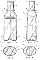
- Figure 1 is a front and rear elevational view of a container embodying the features of the invention illustrating a two-footed support therefore;
- Figure 2 is a left and right side elevational view thereof;
- Figure 3 is a sectional view taken along line 3-3 of Figure 1;
- Figure 4 is a bottom plan view of the embodiment illustrated in Figures 1, 2 and 3;
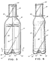
- Figure 5 is a front and rear elevational view of a container embodying the features of the invention illustrating a four-footed support therefore;
- Figure 6 is a left and right side elevational view of the embodiment illustrated in Figure 5;
- Figure 7 is a sectional view taken along line 7-7 of Figure 5;
- Figure 8 is a bottom plan view thereof; and
- Figure 9 is a sectional view taken along line 9-9 of Figure 7.
- Figure 10 is an elevational view of the container with a closure.
- Figure 11 is a horizontal sectional view of the container of Figure 10 without the closure.
- Figure 12 is an elevational view of the dispenser/doser parts of the container of Figure 11 showing side delivery from the dip tubes.
- Figure 13 is an elevational view of the dispenser/doser part of the container of Figure 12 rotated 90 degrees.
- Figure 14 is a top plan view of the container of Figure 11.
- Figure 15 is an elevational view of the container preform.
- Figure 16 is an elevational view of the preform of Figure 15 in a horizontal section.
- Figure 17 is a top plan view of the preform of Figure 15.
- Figure 18 is an elevational view of the core of the mold for the preform.
- Figure 19 is an elevational view in section of the injection mold for making preforms.
- Figure 20 is a bottom view of the injection mold of Figure 19 with an elongated gate pad.
- Figure 21 is an inner surface of a blow mold showing recesses and projections to promote a vertical downward flow of plastic during blow molding.
- With reference to the embodiment illustrated in Figures 1 through 4, there is shown a
container 10 having asidewall 12, abase 14, asidewall shoulder 16, aneck portion 18, and anaperture 20. - A
web 30 is disposed within the interior of thecontainer 10 and is adapted to extend upwardly from the base 14 traversing thesidewall 12, thesidewall shoulder 16, theneck 18 and terminates at theaperture 20. Theweb 30 effectively divides the interior of thecontainer 10 into twodiscrete chambers - The upper end of the
container 10 is provided with a lockingring 36 and typically will include a suitable closure, not shown, to cooperate with the lockingring 36 to effectively close thecontainer 10. - The
base 14 is generally outwardly convex in shape and is provided with an axial inwardly archedlineal impression 40, the inner surface of which forms a juncture with the bottom-most edge of theinternal web 30. It will be readily apparent that the opposing side edges 42 and 44 are integrally joined with the inner surface of thesidewall 12, thesidewall shoulder 16, and theneck portion 18. The interior of thecontainer 10 is thereby formed into thechambers container 10 through theaperture 20. - On opposite sides of the
lineal impression 40 there is formed a pair of opposed outwardly extending petaloidfooted portions footed portions container 10 and further provide impact protection for the lineal juncture between the bottom-most edge of thecentral web 30 and thebase 14. - It will be appreciated should the
container 10 filled with separate liquids, for example, be accidentally allowed to drop on a hard surface, thefooted portions web 30 and the base 14 from direct impact and the possible resultant lifting and separation of the edge of theweb 30 from the base 14 which would allow the otherwise discrete liquids to mix. - Further, it will be understood favorable results have been achieved by forming the
container 10 of polyethylene terephthalate (PET), for example. Such plastic material may be formulated to allow the plastic material which defines thefooted portions central web 30 from thebase 14. - Another embodiment of the invention is illustrated in Figures 5 through 9. The embodiment is very similar to the embodiment of the invention illustrated in Figures 1 through 4 and primed references are used to illustrate structural elements which are the same as those illustrated in Figures 5 through 9. The container 10' has a base 14' which is generally outwardly convex in shape similar to the earlier described embodiment but is provided with a petaloid configuration having a four-footed support rather than the two-footed support described hereinbefore.
- More specfically, the base 14' of the container 10' is provided with an axial inwardly arched lineal impression 40' and a generally laterally disposed axial inwardly arched lineal impression 40''. The resultant base structure includes spaced apart footed portions 46' and 48' disposed on opposite sides of the impression 40', and spaced apart footed
portions - Another embodiment is shown in Figure 10.
Container 50 hassidewall 52,base 54 andsidewall shoulder area 56. Within the container isweb 62 which separates the container into two chambers. The web has a minimum thickness in the central region, that is, a region equidistant from the sidewalls. This will be a thickness of less than about 0.4 mmd, and preferably less than 0.2 mm. Each chamber has adip tube vertical projection 55 and avertical recess 53. These are ornamental in the end product bottle but are used to stabilize the plastic material distribution after contact with the mold during blow molding. At the upper end of the bottle is lockingring 58 andclosure 60. - This bottle is shown in cross-section and without the closure in Figure 11. It is shown that each of
dip tubes fitments 70 which also seal upper dispensing/doser chambers lower containment opening 76. The dispensing/doser chambers are formed byweb 62 andwall 80. The exit of the dispenser/doser section inaperture 84.Threads 82 attach the closure to the container. Theweb 62 extends from the base of the bottle to the dispenser/doser exit 84. - Figure 12 shows the top dispensing/doser section of the container. In this embodiment
dip tube extensions side openings 78 for dispensing product. Lugs 86 (see also Figure 13) are locking lugs that are used to hold the closure securely in place. In Figure 13 thedischarge openings 78 are shown in more detail. - Figure 14 is a top plan view of the container showing the D-shaped
fitments 70 that hold the dip tube extensions and also which seal the dip tubes in the shoulder ofbottle 50. - Figure 15 discloses a preform for making the container of Figure 10. This preform consists of a
plastic tube 90 having asidewall 92 and aninner wall 96.Wall 98 will be the outer wall of the dispenser/doser and of the blown container. In blowing the container thelugs 86 or theinner wall 96 can be used to align the preform in the mold. Alignment is important. For an elliptical bottle the blow mold will be elliptical in shape. The preform will be placed in the mold in different orientations to produce a blow bottle with a web along the major axis, along the minor axis or at an angle to the major axis or minor axis. Since in injection molding the preform thelugs 86 and thecenter wall 96 will always be in the same locations these are useful for reference pionts in aligning the preform in the blow mold. - Figure 16 is a horizontal section of the preform of Figure 15. Figure 17 is a top plan view of the preform.
- Figure 18 shows the core mold for making the preform. The
core mold 100 is comprised of three parts. These arecore base 106 andcore projections void space 108 will produce the inner wall of the preform. In a preferred embodiment surfaces 110 and 112 are recessed at the lower end to producerecesses - Figure 19 shows
core mold 100 in theinjection mold 120. This consists ofmold body 122 andmold gate 124. A gate pad covers part ofgate 124 and regulates the flow of plastic during injection molding.Injection mold 120 is vented at 107 at the top ofinner wall 96. - Figure 20 shows
gate pad 124 with anelongated aperture 126. The objective in Figure 20 is to use a gate pad which will allow for the flow of plastic to control the deflection of the core projections during injection molding. It also is an objective to control any movement ofcore projections recesses recesses - Figure 21 shows a half section 132 of a
blow mold 130 withvarious recesses protrusions Section 134 forms the dispenser/doser of the container. These features will result in the opposite effect in the blown bottle. The objective of these recesses and projections is to promote a vertical flow of plastic along the blow mold wall during the blow mold process. If the plastic does not flow vertically, but at an angle, there can result a spiraling of theinner wall 106 of the preform as the bottle is being formed. - The preform is formed by injection molding by heating the plastic so that it flows and applying a melt pressure of about 2,000 to 20,000 psi. The useful plastics include polypropylene, polyvinyl chloride, acrylonitrile - styrene or their copolymers, polyethylene terephthalate or copolymers or terpolymers thereof, polyethylene naphthalate and polybutylene terephthalate. After being formed the preform is placed in a blow mold and with an internal air pressure of about 100 to 1000 psi in a blow mold and with an internal air pressure of about 100 to 1000 psi is blown to the shape of the mold. Preferably the pressure is about 600 psi.
- The foregoing description describes the preferred and best mode for practicing the present invention. Modifictions to the disclosed embodiments are contemplated to produce particular containers and are considered to be within the scope of the present invention.
- An option with regard to the dip tubes is to mold the dip tubes onto the bottle inner wall as the bottle is made and solely then to insert a seal fitment between the dispenser/doser portion. This reduces the number of parts.
- A further option is to use a telescoping stretch rod technique in blow molding the containers. A telescoping stretch technique provides advantages in the distribution of the air during blowing. This can produce a container with a more uniform web.
Claims (20)
- A plastic blow molded multi-chamber container, said container having sidewalls, a base at one end of said sidewalls with a dispensing means at the other end of said sidewalls and a plurality of separate chambers within said container, each chamber being separate from the base through to a container aperture at said other end, continuous webs within said container and extending from said base to said aperture and separating said container into said plurality of separate chambers, the base having a generally outward convex bottom wall, an axial inwardly arched lineal impression in said base the inner surface of said base in the region of the lineal impression forming a juncture with the bottom-most edge of the webs and outwardly extending footed portions from said base providing impact support for the container.
- A plastic blow molded multi-chamber container as in claim 1 wherein said dispensing means is an integral part of said container and is comprised of an upwardly extending dispensing means sidewall extending from said container sidewall to an exit to form a dispensing chamber, said dispensing chamber having cross-sectional area less than that of said container, said continuous webs extending as a singular unit to an exit of said dispensing chamber to divide said dispensing chamber into a plurality of separate chambers.
- A plastic blow molded multi-chamber container as in claim 2 wherein within said dispensing means there is at least one dip tube sealably supported in the dispensing means between the dispensing means sidewall and said webs, said dip tube extending into said container to adjacent the base of said container, the product to be dispensed flowing up said dip tube upon compression of the container sidewalls and being maintained separated by said web within said dispensing means until flowed therefrom.
- A plastic blow molded multi-chamber container as in claim 2 wherein said container has an elliptical cross-section.
- A plastic blow molded multi-chamber container as in claim 2 wherein said web has the least thickness at a center region thereof.
- A plastic blow molded multi-chamber container as in claim 1 wherein said outwardly extending footed impressions are disposed on opposite sides of the lineal impression formed in said base.
- A plastic blow molded multi-chamber container as in claim 1 wherein said outwardly extending footed portions include at least one footed portion on opposite sides of the lineal impression.
- A plastic blow molded multi-chamber container as in claim 1 including a second axial inwardly arched lineal impression in said base at an angle to said first axial inwardly arched lineal impression.
- The invention defined in claim 8 wherein at least four outwardly extending footed portions are formed.
- A plastic blow molded container as in claim 2 including a closure that is threadedly attached to said dispensing means, said closure having a seal to contact the exit of said dispensing chamber, said seal being rotatable with respect to said closure.
- A method of blow molding a plastic container having a plurality of chambers and a dispensing means comprising:a. forming a preform of said container in a preform mold, said preform including a web to create separate chambers within said container and a closure securing means;b. placing said preform in said blow mold and orienting said preform in said blow mold by one of said web and said closure securing means;c. placing a stretch rod into each separate chamber, said stretch rod contacting said web and supporting said web; andd. injecting air into said perform to produce said container.
- A method of blow molding a plastic container as in claim 11 wherein said web is used to orient said preform within said blow mold.
- A method of blow molding a plastic container as in claim 11 wherein said closure securing means comprises at least two upward by extending projections, said upwardly extending projections aligning said preform in said blow mold.
- A method of blow molding a plastic container in claim 11 wherein said preform mold is vented at the uppermost surface of said web.
- A method of blow molding a plastic container as in claim 11 wherein a separate stretch rod is inserted into each chamber.
- An injection mold for a multi-chamber preform container comprising:a. a mold body;b. a mold core comprised of at least a base and a plurality of separate projections extending from said base having a shape related to the shape of said multi-chamber container; andc. a gate pad at the bottom of said mold body for the injection of plastic into said mold body, said gate pad having an elongated shape.
- An injection mold as in claim 16 wherein each of said projections has a recess adjacent the end thereof.
- A blow mold for molding multi-chamber containers, said blow mold having on a surface for forming a container at least one of vertically oriented projections and vertically oriented recesses to guide the flow of plastic vertically during blow molding.
- A blow mold as in claim 18 wherein there are vertically oriented projections to guide the flow of plastic during blow molding.
- A blow mold as in claim 18 wherein there are vertically oriented recesses to guide the flow of plastic during blow molding.
Applications Claiming Priority (4)
| Application Number | Priority Date | Filing Date | Title |
|---|---|---|---|
| US08/310,557 US5573143A (en) | 1994-09-21 | 1994-09-21 | Blow molded multi-chamber containers with dispenser/doser |
| US310557 | 1994-09-21 | ||
| US08/339,940 US5482170A (en) | 1994-11-15 | 1994-11-15 | Multi-chamber containers |
| US339940 | 1994-11-15 |
Publications (3)
| Publication Number | Publication Date |
|---|---|
| EP0703153A2 true EP0703153A2 (en) | 1996-03-27 |
| EP0703153A3 EP0703153A3 (en) | 1996-08-14 |
| EP0703153B1 EP0703153B1 (en) | 2001-01-03 |
Family
ID=26977468
Family Applications (1)
| Application Number | Title | Priority Date | Filing Date |
|---|---|---|---|
| EP19950202539 Expired - Lifetime EP0703153B1 (en) | 1994-09-21 | 1995-09-20 | Multi-chamber container |
Country Status (10)
| Country | Link |
|---|---|
| EP (1) | EP0703153B1 (en) |
| AT (1) | ATE198454T1 (en) |
| AU (1) | AU689292B2 (en) |
| BR (1) | BR9504069A (en) |
| CA (1) | CA2158705C (en) |
| DE (1) | DE69519778T2 (en) |
| GR (1) | GR3035696T3 (en) |
| HU (1) | HUT72722A (en) |
| PT (1) | PT703153E (en) |
| RO (1) | RO117168B1 (en) |
Cited By (7)
| Publication number | Priority date | Publication date | Assignee | Title |
|---|---|---|---|---|
| WO1998019928A1 (en) * | 1996-11-01 | 1998-05-14 | Colgate-Palmolive Company | Injection stretch blow molded tubular containers |
| WO1998028121A1 (en) * | 1996-12-20 | 1998-07-02 | Colgate-Palmolive Company | Multichamber container with expanded interior walls |
| US6039215A (en) * | 1998-06-12 | 2000-03-21 | The Procter & Gamble Company | Dual product pump dispenser with multi-outlet closure for product separation |
| WO2000071478A2 (en) * | 1999-05-24 | 2000-11-30 | Perez San Vicente Ruiz Jose Ar | Methods for producing internally divided containers, bottles, glasses and the like and bifurcated straws and resulting products |
| WO2002022467A1 (en) * | 2000-09-15 | 2002-03-21 | The Procter & Gamble Company | Multi-compartment container and dispensing device |
| KR100437877B1 (en) * | 1997-05-09 | 2004-10-14 | 주식회사 엘지생활건강 | Dispense type double container capable of separately receiving liquids and using the liquids at the same time and method for manufacturing thereof |
| WO2007038071A3 (en) * | 2005-09-23 | 2008-07-03 | Graham Packaging Co | Blow molded container, dispenser, and closure |
Citations (3)
| Publication number | Priority date | Publication date | Assignee | Title |
|---|---|---|---|---|
| US5158191A (en) | 1991-03-01 | 1992-10-27 | Plastic Processing Corporation | Dual bottle container having a dual outlet cap |
| US5232108A (en) | 1991-02-09 | 1993-08-03 | Nissei Asb Machine Co., Ltd. | Preform having inner partition wall and process of making plastic vessel having inner partition wall |
| US5242066A (en) | 1988-11-16 | 1993-09-07 | Whitbread & Company Plc | Plastic bottles and similar containers having internal spiders |
Family Cites Families (5)
| Publication number | Priority date | Publication date | Assignee | Title |
|---|---|---|---|---|
| US873955A (en) * | 1907-06-25 | 1907-12-17 | Charles C Mcclintock | Trolley-head. |
| US3347420A (en) * | 1965-08-16 | 1967-10-17 | Robert J Donoghue | Multi-compartment container for dispensing measured quantities of a plurality of liquids |
| US4070140A (en) * | 1974-07-31 | 1978-01-24 | The Procter & Gamble Company | Apparatus for making precisely partitioned bulbous-shape container |
| JPH03236932A (en) * | 1990-02-15 | 1991-10-22 | Yoshida Kogyo Kk <Ykk> | Container and method and apparatus for preparing the same |
| US5024340A (en) * | 1990-07-23 | 1991-06-18 | Sewell Plastics, Inc. | Wide stance footed bottle |
-
1995
- 1995-09-06 AU AU30499/95A patent/AU689292B2/en not_active Expired
- 1995-09-14 HU HU9502689A patent/HUT72722A/en unknown
- 1995-09-19 BR BR9504069A patent/BR9504069A/en not_active IP Right Cessation
- 1995-09-20 RO RO95-01643A patent/RO117168B1/en unknown
- 1995-09-20 EP EP19950202539 patent/EP0703153B1/en not_active Expired - Lifetime
- 1995-09-20 DE DE1995619778 patent/DE69519778T2/en not_active Expired - Lifetime
- 1995-09-20 PT PT95202539T patent/PT703153E/en unknown
- 1995-09-20 AT AT95202539T patent/ATE198454T1/en not_active IP Right Cessation
- 1995-09-20 CA CA 2158705 patent/CA2158705C/en not_active Expired - Lifetime
-
2001
- 2001-04-03 GR GR20010400547T patent/GR3035696T3/en not_active IP Right Cessation
Patent Citations (3)
| Publication number | Priority date | Publication date | Assignee | Title |
|---|---|---|---|---|
| US5242066A (en) | 1988-11-16 | 1993-09-07 | Whitbread & Company Plc | Plastic bottles and similar containers having internal spiders |
| US5232108A (en) | 1991-02-09 | 1993-08-03 | Nissei Asb Machine Co., Ltd. | Preform having inner partition wall and process of making plastic vessel having inner partition wall |
| US5158191A (en) | 1991-03-01 | 1992-10-27 | Plastic Processing Corporation | Dual bottle container having a dual outlet cap |
Cited By (12)
| Publication number | Priority date | Publication date | Assignee | Title |
|---|---|---|---|---|
| WO1998019928A1 (en) * | 1996-11-01 | 1998-05-14 | Colgate-Palmolive Company | Injection stretch blow molded tubular containers |
| US5954224A (en) * | 1996-11-01 | 1999-09-21 | Colgate-Palmolive Company | Injection stretch blow molded tubular containers |
| US6168041B1 (en) | 1996-11-01 | 2001-01-02 | Colgate-Palmolive Company | Injection stretch blow molded tubular containers |
| WO1998028121A1 (en) * | 1996-12-20 | 1998-07-02 | Colgate-Palmolive Company | Multichamber container with expanded interior walls |
| US5849241A (en) * | 1996-12-20 | 1998-12-15 | Colgate-Palmolive Company | Multichamber container with expanded interior walls |
| CN1065814C (en) * | 1996-12-20 | 2001-05-16 | 科尔加特·帕尔莫利弗公司 | Multichamber container with expanded interior walls |
| KR100437877B1 (en) * | 1997-05-09 | 2004-10-14 | 주식회사 엘지생활건강 | Dispense type double container capable of separately receiving liquids and using the liquids at the same time and method for manufacturing thereof |
| US6039215A (en) * | 1998-06-12 | 2000-03-21 | The Procter & Gamble Company | Dual product pump dispenser with multi-outlet closure for product separation |
| WO2000071478A2 (en) * | 1999-05-24 | 2000-11-30 | Perez San Vicente Ruiz Jose Ar | Methods for producing internally divided containers, bottles, glasses and the like and bifurcated straws and resulting products |
| WO2000071478A3 (en) * | 1999-05-24 | 2001-04-26 | San Vicente Ruiz Jose Ar Perez | Methods for producing internally divided containers, bottles, glasses and the like and bifurcated straws and resulting products |
| WO2002022467A1 (en) * | 2000-09-15 | 2002-03-21 | The Procter & Gamble Company | Multi-compartment container and dispensing device |
| WO2007038071A3 (en) * | 2005-09-23 | 2008-07-03 | Graham Packaging Co | Blow molded container, dispenser, and closure |
Also Published As
| Publication number | Publication date |
|---|---|
| CA2158705A1 (en) | 1996-03-22 |
| HUT72722A (en) | 1996-05-28 |
| DE69519778D1 (en) | 2001-02-08 |
| EP0703153B1 (en) | 2001-01-03 |
| HU9502689D0 (en) | 1995-11-28 |
| AU689292B2 (en) | 1998-03-26 |
| AU3049995A (en) | 1996-04-04 |
| CA2158705C (en) | 2007-02-06 |
| EP0703153A3 (en) | 1996-08-14 |
| RO117168B1 (en) | 2001-11-30 |
| ATE198454T1 (en) | 2001-01-15 |
| DE69519778T2 (en) | 2001-08-16 |
| BR9504069A (en) | 1996-09-24 |
| PT703153E (en) | 2001-06-29 |
| GR3035696T3 (en) | 2001-07-31 |
Similar Documents
| Publication | Publication Date | Title |
|---|---|---|
| US5804227A (en) | Inspection mold for a multi-chamber container preform | |
| US5482170A (en) | Multi-chamber containers | |
| AU605139B2 (en) | Improvements in or relating to plastics containers | |
| US9387971B2 (en) | Plastic container having a deep-set invertible base and related methods | |
| US7882971B2 (en) | Rectangular container with vacuum panels | |
| CN1042817C (en) | Blow molded plastic container including handgrip | |
| US8087525B2 (en) | Multi-panel plastic container | |
| US6179143B1 (en) | Handled plastic container | |
| EP0348029B1 (en) | Blow moulded container with self- supporting base | |
| CA1206896A (en) | Container with a catenary-formed contour | |
| US4603831A (en) | Mold core member for use in a mold unit for injection molding a plastic material preform for a blow molded container | |
| EP2738108B1 (en) | Plastics container | |
| MXPA97003516A (en) | Plastic container with ma | |
| US6550627B2 (en) | Container | |
| EP0703153B1 (en) | Multi-chamber container | |
| CA2690157C (en) | Container with recessed removable venting tab | |
| AU688043B2 (en) | Venting thermoplastic container for a package with a bladder system | |
| EP1710166A2 (en) | Handled plastic container | |
| EP0620795A1 (en) | Cap for a bottle. | |
| JPH0834422A (en) | Bottle-like container for liquid | |
| CA2265546A1 (en) | Non-rocking, webbed container for carbonated beverages |
Legal Events
| Date | Code | Title | Description |
|---|---|---|---|
| PUAI | Public reference made under article 153(3) epc to a published international application that has entered the european phase |
Free format text: ORIGINAL CODE: 0009012 |
|
| AK | Designated contracting states |
Kind code of ref document: A2 Designated state(s): AT BE CH DE DK ES FR GB GR IE IT LI NL PT SE |
|
| PUAL | Search report despatched |
Free format text: ORIGINAL CODE: 0009013 |
|
| AK | Designated contracting states |
Kind code of ref document: A3 Designated state(s): AT BE CH DE DK ES FR GB GR IE IT LI NL PT SE |
|
| 17P | Request for examination filed |
Effective date: 19970128 |
|
| 17Q | First examination report despatched |
Effective date: 19980130 |
|
| GRAG | Despatch of communication of intention to grant |
Free format text: ORIGINAL CODE: EPIDOS AGRA |
|
| GRAG | Despatch of communication of intention to grant |
Free format text: ORIGINAL CODE: EPIDOS AGRA |
|
| GRAH | Despatch of communication of intention to grant a patent |
Free format text: ORIGINAL CODE: EPIDOS IGRA |
|
| GRAH | Despatch of communication of intention to grant a patent |
Free format text: ORIGINAL CODE: EPIDOS IGRA |
|
| GRAA | (expected) grant |
Free format text: ORIGINAL CODE: 0009210 |
|
| AK | Designated contracting states |
Kind code of ref document: B1 Designated state(s): AT BE CH DE DK ES FR GB GR IE IT LI NL PT SE |
|
| PG25 | Lapsed in a contracting state [announced via postgrant information from national office to epo] |
Ref country code: SE Free format text: THE PATENT HAS BEEN ANNULLED BY A DECISION OF A NATIONAL AUTHORITY Effective date: 20010103 Ref country code: NL Free format text: LAPSE BECAUSE OF FAILURE TO SUBMIT A TRANSLATION OF THE DESCRIPTION OR TO PAY THE FEE WITHIN THE PRESCRIBED TIME-LIMIT Effective date: 20010103 Ref country code: LI Free format text: LAPSE BECAUSE OF FAILURE TO SUBMIT A TRANSLATION OF THE DESCRIPTION OR TO PAY THE FEE WITHIN THE PRESCRIBED TIME-LIMIT Effective date: 20010103 Ref country code: ES Free format text: THE PATENT HAS BEEN ANNULLED BY A DECISION OF A NATIONAL AUTHORITY Effective date: 20010103 Ref country code: CH Free format text: LAPSE BECAUSE OF FAILURE TO SUBMIT A TRANSLATION OF THE DESCRIPTION OR TO PAY THE FEE WITHIN THE PRESCRIBED TIME-LIMIT Effective date: 20010103 Ref country code: BE Free format text: LAPSE BECAUSE OF FAILURE TO SUBMIT A TRANSLATION OF THE DESCRIPTION OR TO PAY THE FEE WITHIN THE PRESCRIBED TIME-LIMIT Effective date: 20010103 Ref country code: AT Free format text: LAPSE BECAUSE OF FAILURE TO SUBMIT A TRANSLATION OF THE DESCRIPTION OR TO PAY THE FEE WITHIN THE PRESCRIBED TIME-LIMIT Effective date: 20010103 |
|
| REF | Corresponds to: |
Ref document number: 198454 Country of ref document: AT Date of ref document: 20010115 Kind code of ref document: T |
|
| REG | Reference to a national code |
Ref country code: CH Ref legal event code: EP |
|
| REG | Reference to a national code |
Ref country code: IE Ref legal event code: FG4D |
|
| REF | Corresponds to: |
Ref document number: 69519778 Country of ref document: DE Date of ref document: 20010208 |
|
| ITF | It: translation for a ep patent filed |
Owner name: BARZANO' E ZANARDO ROMA S.P.A. |
|
| PG25 | Lapsed in a contracting state [announced via postgrant information from national office to epo] |
Ref country code: DK Free format text: LAPSE BECAUSE OF FAILURE TO SUBMIT A TRANSLATION OF THE DESCRIPTION OR TO PAY THE FEE WITHIN THE PRESCRIBED TIME-LIMIT Effective date: 20010403 |
|
| ET | Fr: translation filed | ||
| NLV1 | Nl: lapsed or annulled due to failure to fulfill the requirements of art. 29p and 29m of the patents act | ||
| REG | Reference to a national code |
Ref country code: PT Ref legal event code: SC4A Free format text: AVAILABILITY OF NATIONAL TRANSLATION Effective date: 20010330 |
|
| REG | Reference to a national code |
Ref country code: CH Ref legal event code: PL |
|
| PG25 | Lapsed in a contracting state [announced via postgrant information from national office to epo] |
Ref country code: IE Free format text: LAPSE BECAUSE OF NON-PAYMENT OF DUE FEES Effective date: 20010920 |
|
| PLBE | No opposition filed within time limit |
Free format text: ORIGINAL CODE: 0009261 |
|
| STAA | Information on the status of an ep patent application or granted ep patent |
Free format text: STATUS: NO OPPOSITION FILED WITHIN TIME LIMIT |
|
| REG | Reference to a national code |
Ref country code: GB Ref legal event code: IF02 |
|
| 26N | No opposition filed | ||
| REG | Reference to a national code |
Ref country code: IE Ref legal event code: MM4A |
|
| PGFP | Annual fee paid to national office [announced via postgrant information from national office to epo] |
Ref country code: GR Payment date: 20040727 Year of fee payment: 10 |
|
| PGFP | Annual fee paid to national office [announced via postgrant information from national office to epo] |
Ref country code: PT Payment date: 20040827 Year of fee payment: 10 |
|
| PG25 | Lapsed in a contracting state [announced via postgrant information from national office to epo] |
Ref country code: PT Free format text: LAPSE BECAUSE OF NON-PAYMENT OF DUE FEES Effective date: 20060320 |
|
| REG | Reference to a national code |
Ref country code: PT Ref legal event code: MM4A Effective date: 20060320 |
|
| PG25 | Lapsed in a contracting state [announced via postgrant information from national office to epo] |
Ref country code: GR Free format text: LAPSE BECAUSE OF NON-PAYMENT OF DUE FEES Effective date: 20010103 |
|
| PGFP | Annual fee paid to national office [announced via postgrant information from national office to epo] |
Ref country code: FR Payment date: 20140825 Year of fee payment: 20 Ref country code: GB Payment date: 20140826 Year of fee payment: 20 |
|
| PGFP | Annual fee paid to national office [announced via postgrant information from national office to epo] |
Ref country code: IT Payment date: 20140918 Year of fee payment: 20 |
|
| PGFP | Annual fee paid to national office [announced via postgrant information from national office to epo] |
Ref country code: DE Payment date: 20140930 Year of fee payment: 20 |
|
| REG | Reference to a national code |
Ref country code: DE Ref legal event code: R071 Ref document number: 69519778 Country of ref document: DE |
|
| REG | Reference to a national code |
Ref country code: GB Ref legal event code: PE20 Expiry date: 20150919 |
|
| PG25 | Lapsed in a contracting state [announced via postgrant information from national office to epo] |
Ref country code: GB Free format text: LAPSE BECAUSE OF EXPIRATION OF PROTECTION Effective date: 20150919 |