EP0702807B1 - Systeme et dispositif de pre-automatisation des installations d'un batiment - Google Patents
Systeme et dispositif de pre-automatisation des installations d'un batiment Download PDFInfo
- Publication number
- EP0702807B1 EP0702807B1 EP95916719A EP95916719A EP0702807B1 EP 0702807 B1 EP0702807 B1 EP 0702807B1 EP 95916719 A EP95916719 A EP 95916719A EP 95916719 A EP95916719 A EP 95916719A EP 0702807 B1 EP0702807 B1 EP 0702807B1
- Authority
- EP
- European Patent Office
- Prior art keywords
- sensors
- mentioned
- cables
- actuators
- building
- Prior art date
- Legal status (The legal status is an assumption and is not a legal conclusion. Google has not performed a legal analysis and makes no representation as to the accuracy of the status listed.)
- Expired - Lifetime
Links
Images

Classifications
-
- G—PHYSICS
- G05—CONTROLLING; REGULATING
- G05B—CONTROL OR REGULATING SYSTEMS IN GENERAL; FUNCTIONAL ELEMENTS OF SUCH SYSTEMS; MONITORING OR TESTING ARRANGEMENTS FOR SUCH SYSTEMS OR ELEMENTS
- G05B19/00—Programme-control systems
- G05B19/02—Programme-control systems electric
- G05B19/04—Programme control other than numerical control, i.e. in sequence controllers or logic controllers
- G05B19/042—Programme control other than numerical control, i.e. in sequence controllers or logic controllers using digital processors
Definitions
- the invention relates, in general, building automation and more in particular, a system which allows pre-automate industrial, tertiary or others with a view to installing various equipment and facilities.
- industrial and tertiary buildings or others include equipment and facilities to ensure their technical and administrative management in the fields of air conditioning, security, access control, schedule management and visitors.
- These equipments and installations include sensors that provide, in each cited area, information to a dedicated controller that develops control signals from actuators in the same domain located at different locations in the building.
- a unit supervision which centralizes information for their surveillance, this unit can be common to several installations.
- US-A-4,567,557 describes a system for monitoring sensors and actuators in a building comprising a monitoring system for collecting information centrally from the sensors and controlling the actuators and also comprising devices interconnection devices which connect to actuators and sensors by a terminal block connected via input / output devices to a microprocessor.
- each of the equipment and installations can be pre-wired in a similar way to computer and telephone equipment but it for each device, it is a pre-wired network different which only includes passive elements such only cables and terminal blocks.
- One of the aims of the present invention is therefore to realize a pre-automation system of a industrial, tertiary or other building that allows supervise all or part of all the sensors and actuators from at least one management domain located in a certain area of the building.
- Another object of the present invention is to provide a pre-automation system for an industrial building, tertiary or other including several devices interconnection distributed in the building which are connected to each other and to at least one unit of supervision by a pre-wiring network.
- the subject of the invention is a system for monitoring sensors and actuators as defined in claim 1.
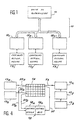
- Each interconnection device 12 1 to 12 n is respectively connected to sensors and actuators referenced 13 1 to 13 n .
- Each interconnection device 12 comprises at least (FIGS. 2 and 3) a terminal block 14, 14 'whose terminals are connected on the one hand as indicated above, by conductors 15, 15' to sensors 13 and actuators 13 'and, on the other hand, by conductors 16, 16' to an automaton 17.
- the automaton 17 comprises an input / output circuit 18 which is connected, on the one hand, to terminals 14, 14 'and , on the other hand, to a microprogrammed unit 19 such as a microprocessor.
- the input / output circuit 18 is also connected to the supervision unit 11 (FIG. 1) by the network of cables 10. Furthermore, the microprocessor 19 can be connected to a laptop 20 by a cable 21.
- the input / output circuit 18 is designed to be connected, via the terminal block 14, to sensors 13 a , 13 b (FIG. 4) by conductors 22 a , 27 a and 22 b , 27 b in a star and to sensors 13 x , 13 y and 13 z in series by a bus 23, 30.
- the microprocessor of the microprocessor 19 can be carried out either from the supervision unit 11, either from the laptop 20.
- the microprocessor 19 comprises in known manner a mainframe, RAM and ROM which contains the function processing program defined above.
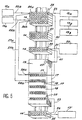
- the different elements of a device interconnection according to the invention are mounted on a pre-wiring farm 25 in which the pre-wiring network cables as shown in the figure 5.
- the sensors 13 a and 13 b are connected respectively by cables 22 a , 22 b to terminals 24 a , 24 b of the terminal block 14 by its rear face. These terminals 24 a , 24 b are connected, by the front face of the terminal block, respectively by cables 27 a , 27 b to two inputs 28 a , 28 b of the input / output circuit 18.
- the sensors 13 x , 13 y and 13 z are connected by a bus 23 to a terminal 28, by its rear face of the terminal block; the latter is connected by the front face of the terminal block to an input terminal 31 of the input / output circuit 18 by a cable 30.
- an actuator 13 ' receives a signal electric via an output terminal 32 of the input / output circuit 18, of a first, cable 33 which connects it to a terminal 35 of the terminal block 14 'by its front face, and a second cable 36 between the face rear of terminal 35 and actuator 13 '.
- Cables 22 a , 22 b , 23 and 36 are part of the pre-wiring network and are connected to terminal block 14, 14 'by the rear face while cables 27 a , 27 b , 30 and 33 are installed at demand and are connected to the terminal block by the front panel.
- the input / output terminals of the input / output circuit 18 can be of any known type and present each a coded marking 37 and a warning light signage 38.
- the laptop 20 is connected to the microprocessor 19 via cable 21, an input terminal 39 of terminal block 14, an output terminal 40 and a cable 41 connected to a special socket 42 of the microprocessor 19.
- the cable 21 can be connected directly to the special socket 42.
- each interconnection device is intended to be connected to twenty-five sensors and / or actuators and it is therefore necessary to install forty devices for a system a thousand measuring points.
Description
- la figure 1 est un schéma fonctionnel d'un système de pré-automatisation des installations d'un bâtiment industriel, tertiaire ou autre, selon l'invention;
- les figures 2 et 3 sont des schémas fonctionnels d'un appareil d'interconnexion selon la présente invention;
- la fiqure 4 est une vue schématique de câblages en étoile et en bus d'un appareil d'interconnexion, et
- la figure 5 est une vue d'un appareil d'interconnexion selon l'invention tel qu'il est monté sur un support de pré-câblage.
- l'acquisition d'informations en provenance des capteurs 13,
- la mémorisation des informations en provenance des capteurs 13 avec leur date et leur heure d'acquisition,
- la gestion des communications avec l'unité de supervision 11,
- le contrôle d'accès, la gestion des horaires et la régulation, en local, sans l'intervention de l'unité de supervision 11, et
- toutes autres fonctions qui peuvent être nécessaires pour une Gestion Technique du Bâtiment ou une Gestion Administrative Centralisée.
Claims (3)
- Un système permettant de superviser des capteurs (13) et des actionneurs (13) dans un bâtiment, composé:d'un système de supervision (11) permettant de recueillir les informations au niveau central à partir desdits capteurs (13) et de contrôler lesdits actionneurs (13')de divers appareils d'interconnexion (121, 122, ...12n) qui se connectent aux actionneurs (13') et aux capteurs précités, comprenant:a) divers borniers (14, 14') reliées aux capteurs précités (13) et aux actionneurs (13') par des conducteurs d'une première série de câbles (15, 15');b) un microprocesseur (19) présentant diverses connexions entrée/sortie, une partie d'entre elles étant reliée aux borniers précités (14, 14') par des conducteurs d'une seconde série de câbles (16, 16') afin de transmettre des signaux permettant de contrôler lesdits actionneurs (13') et de recevoir des signaux à partir des capteurs précités (13); ainsi qu'un système de précâblage (10) se trouvant dans ledit bâtiment, reliant le système de supervision précité (11) à une partie restante desdites connexions entrée/sortie, dans lequelc) lesdits signaux peuvent être transférés vers et à partir des appareils d'interconnexion et du système de supervision précité (11) et la première série de câbles précitée (15) correspond à des câbles précâblés dans ledit bâtiment etd) dans lequel ladite partie des connexions entrée/sortie précitées comprend une connexion étoile avec certains capteurs précités (13) et une connexion bus avec d'autres capteurs précités (13).
- Le système conformément à la revendication 1, dans lequel ledit microprocesseur (19) comprend une douille pour un branchement à un ordinateur portable qui programme ledit microprocesseur.
- Le système conformément à la revendication 2, dans lequel lesdits appareils d'interconnexion sont soutenus sur ledit système de précâblage (10).
Applications Claiming Priority (3)
| Application Number | Priority Date | Filing Date | Title |
|---|---|---|---|
| FR9404157A FR2718543B1 (fr) | 1994-04-08 | 1994-04-08 | Système et dispositif de pré-automatisation des installations d'un bâtiment. |
| FR9404157 | 1994-04-08 | ||
| PCT/FR1995/000442 WO1995027929A1 (fr) | 1994-04-08 | 1995-04-06 | Systeme et dispositif de pre-automatisation des installations d'un batiment |
Publications (2)
| Publication Number | Publication Date |
|---|---|
| EP0702807A1 EP0702807A1 (fr) | 1996-03-27 |
| EP0702807B1 true EP0702807B1 (fr) | 2002-08-28 |
Family
ID=9461888
Family Applications (1)
| Application Number | Title | Priority Date | Filing Date |
|---|---|---|---|
| EP95916719A Expired - Lifetime EP0702807B1 (fr) | 1994-04-08 | 1995-04-06 | Systeme et dispositif de pre-automatisation des installations d'un batiment |
Country Status (8)
| Country | Link |
|---|---|
| US (1) | US6059439A (fr) |
| EP (1) | EP0702807B1 (fr) |
| JP (1) | JP3058448B2 (fr) |
| AT (1) | ATE223077T1 (fr) |
| CA (1) | CA2164611C (fr) |
| DE (1) | DE69527902T2 (fr) |
| FR (1) | FR2718543B1 (fr) |
| WO (1) | WO1995027929A1 (fr) |
Families Citing this family (9)
| Publication number | Priority date | Publication date | Assignee | Title |
|---|---|---|---|---|
| RU2133490C1 (ru) * | 1998-09-21 | 1999-07-20 | Гинзбург Виталий Вениаминович | Структурированная система мониторинга и управления инженерным оборудованием объекта |
| DE19964156B4 (de) * | 1999-01-25 | 2004-07-15 | Weidmüller Interface Gmbh & Co. | Elektrisches Gerät |
| ATE287101T1 (de) * | 1999-11-01 | 2005-01-15 | Abb Research Ltd | Integration eines feldleitgerätes in ein anlagenleitsystem |
| US20040000503A1 (en) * | 2002-06-28 | 2004-01-01 | Shah Ketan N. | Recloseable storage bag with porous evacuation portal |
| US6812848B2 (en) | 2002-08-12 | 2004-11-02 | Flo-Guard Water Leak Mitigation Systems, Llc | Water leak mitigation system |
| US7030767B2 (en) * | 2002-08-12 | 2006-04-18 | Flo-Guard Water Leak Mitigation Systems, L.L.C. | Water leak mitigation system |
| US7413336B2 (en) | 2003-08-29 | 2008-08-19 | 3M Innovative Properties Company | Adhesive stacking for multiple optical films |
| US7777832B2 (en) | 2005-11-18 | 2010-08-17 | 3M Innovative Properties Company | Multi-function enhancement film |
| US20100109577A1 (en) * | 2008-11-05 | 2010-05-06 | Loughrey James F | Cascading addressable mastering protocol-based lighting system |
Family Cites Families (14)
| Publication number | Priority date | Publication date | Assignee | Title |
|---|---|---|---|---|
| US4275455A (en) * | 1977-07-11 | 1981-06-23 | Automation Systems, Inc. | Output interface card suitable for use with a programmable logic controller |
| CH629059A5 (de) * | 1978-02-08 | 1982-03-31 | Landis & Gyr Ag | Mit anschlussorganen fuer anschlussdraehte versehene elektrische anschlussplatte. |
| US4567557A (en) * | 1983-02-23 | 1986-01-28 | Burns Martin J | Building intelligence system |
| FR2589259B1 (fr) * | 1985-10-24 | 1988-08-26 | Frachet Jean Paul | Dispositif de raccordement modulaire des organes d'une installation industrielle a une unite de commande programmable |
| US5001358A (en) * | 1988-02-19 | 1991-03-19 | Omron Tateisi Electronics Co. | Interface device |
| EP0345493B1 (fr) * | 1988-06-08 | 1994-03-09 | Landis & Gyr Technology Innovation AG | Dispositif de surveillance, de commande et de régulation d'une installation technique de systèmes d'automation de bâtiments |
| JPH0278341A (ja) * | 1988-09-14 | 1990-03-19 | Secom Co Ltd | 階層化バス・スター型複合通信システム |
| US5086385A (en) * | 1989-01-31 | 1992-02-04 | Custom Command Systems | Expandable home automation system |
| SE466931B (sv) * | 1990-08-29 | 1992-04-27 | Asea Brown Boveri | Processanpassningssystem |
| DE4223193A1 (de) * | 1992-07-15 | 1994-01-20 | Abb Patent Gmbh | Programmierbare Steuerung mit Anschlußeinheiten zur Verbindung mit analogen und/oder digitalen Peripheriegeräten |
| US5621662A (en) * | 1994-02-15 | 1997-04-15 | Intellinet, Inc. | Home automation system |
| US5528215A (en) * | 1994-05-31 | 1996-06-18 | Landis & Gyr Powers, Inc. | Building automation system having expansion modules |
| US5510975A (en) * | 1994-07-01 | 1996-04-23 | Atlantic Software, Inc. | Method of logical operations in home automation |
| DE4438804C1 (de) * | 1994-10-31 | 1996-03-28 | Weidmueller Interface | Modulare Steuerungsanlage mit Busleiter z. B. zur Gebäudeautomatisierung |
-
1994
- 1994-04-08 FR FR9404157A patent/FR2718543B1/fr not_active Expired - Fee Related
-
1995
- 1995-04-06 JP JP7526121A patent/JP3058448B2/ja not_active Expired - Fee Related
- 1995-04-06 CA CA002164611A patent/CA2164611C/fr not_active Expired - Fee Related
- 1995-04-06 US US08/557,043 patent/US6059439A/en not_active Expired - Fee Related
- 1995-04-06 EP EP95916719A patent/EP0702807B1/fr not_active Expired - Lifetime
- 1995-04-06 DE DE69527902T patent/DE69527902T2/de not_active Expired - Fee Related
- 1995-04-06 WO PCT/FR1995/000442 patent/WO1995027929A1/fr active IP Right Grant
- 1995-04-06 AT AT95916719T patent/ATE223077T1/de not_active IP Right Cessation
Also Published As
| Publication number | Publication date |
|---|---|
| CA2164611C (fr) | 2000-10-31 |
| ATE223077T1 (de) | 2002-09-15 |
| DE69527902T2 (de) | 2003-01-02 |
| FR2718543A1 (fr) | 1995-10-13 |
| FR2718543B1 (fr) | 1996-06-21 |
| JP3058448B2 (ja) | 2000-07-04 |
| US6059439A (en) | 2000-05-09 |
| EP0702807A1 (fr) | 1996-03-27 |
| DE69527902D1 (de) | 2002-10-02 |
| JPH09504400A (ja) | 1997-04-28 |
| WO1995027929A1 (fr) | 1995-10-19 |
Similar Documents
| Publication | Publication Date | Title |
|---|---|---|
| US4771865A (en) | System for the remote management of elevator installations | |
| EP0702807B1 (fr) | Systeme et dispositif de pre-automatisation des installations d'un batiment | |
| CN101490632B (zh) | 楼宇自动化系统 | |
| EP1117018B1 (fr) | Systeme structure de controle et de commande de l'equipement technique d'une installation | |
| FR2922664A1 (fr) | Procede de generation automatique d'un fichier ssd. | |
| GB2396920A (en) | Real-time viewing of turbine monitoring system data | |
| FR2904486A1 (fr) | Procede et systeme de gestion et de modulation en temps reel de consommation electrique. | |
| CN102027330A (zh) | 数据采集模块以及系统 | |
| FR2962617A1 (fr) | Reseau de communication distribue, modulaire et configurable pour un systeme avionique embarque. | |
| CN104050807A (zh) | 一种在线停车场管理系统 | |
| WO2020027538A1 (fr) | Dispositif et procédé de détermination d'anomalie éventuelle de système de génération de puissance | |
| CN111612930B (zh) | 一种考勤系统及方法 | |
| US20160299515A1 (en) | Unitary telematic system for space management, with a universal general purpose | |
| CN114755223A (zh) | 一种电子设备接线监测方法、装置和系统 | |
| Atanassov | Advanced software architecture of an automatic vehicle number plate recognition system | |
| EP0410873B1 (fr) | Dispositif d'interconnexion et d'extension de bus dans un réseau de transmission d'informations | |
| CN103926906A (zh) | 一种工业现场总线系统 | |
| FR2695279A1 (fr) | Dispositif de répartition automatique de liaisons téléphoniques et informatiques. | |
| CN113160468A (zh) | 一种油气站场无人值守系统 | |
| FR3074344A1 (fr) | Systeme et procede de supervision de batiment | |
| EP3672107B1 (fr) | Appareillage de distribution électrique équipé de modules amovibles communiquant par faisceaux optiques sans fils | |
| CN117239938B (zh) | 一种配电站的巡检控制方法、装置、系统、设备及介质 | |
| FR2744868A1 (fr) | Systeme de brassage informatique | |
| CN116566968A (zh) | 一种基于云技术的分布式网络数据远程抓取系统 | |
| Wiecha et al. | Fully integrated control system for the Discovery Channel Telescope |
Legal Events
| Date | Code | Title | Description |
|---|---|---|---|
| PUAI | Public reference made under article 153(3) epc to a published international application that has entered the european phase |
Free format text: ORIGINAL CODE: 0009012 |
|
| AK | Designated contracting states |
Kind code of ref document: A1 Designated state(s): AT BE CH DE DK ES FR GB IE IT LI LU MC NL SE |
|
| 17P | Request for examination filed |
Effective date: 19960328 |
|
| 17Q | First examination report despatched |
Effective date: 19990616 |
|
| GRAG | Despatch of communication of intention to grant |
Free format text: ORIGINAL CODE: EPIDOS AGRA |
|
| GRAG | Despatch of communication of intention to grant |
Free format text: ORIGINAL CODE: EPIDOS AGRA |
|
| GRAH | Despatch of communication of intention to grant a patent |
Free format text: ORIGINAL CODE: EPIDOS IGRA |
|
| GRAH | Despatch of communication of intention to grant a patent |
Free format text: ORIGINAL CODE: EPIDOS IGRA |
|
| GRAA | (expected) grant |
Free format text: ORIGINAL CODE: 0009210 |
|
| AK | Designated contracting states |
Kind code of ref document: B1 Designated state(s): AT BE CH DE DK ES FR GB IE IT LI LU MC NL SE |
|
| PG25 | Lapsed in a contracting state [announced via postgrant information from national office to epo] |
Ref country code: NL Free format text: LAPSE BECAUSE OF FAILURE TO SUBMIT A TRANSLATION OF THE DESCRIPTION OR TO PAY THE FEE WITHIN THE PRESCRIBED TIME-LIMIT Effective date: 20020828 Ref country code: IT Free format text: LAPSE BECAUSE OF FAILURE TO SUBMIT A TRANSLATION OF THE DESCRIPTION OR TO PAY THE FEE WITHIN THE PRESCRIBED TIME-LIMIT;WARNING: LAPSES OF ITALIAN PATENTS WITH EFFECTIVE DATE BEFORE 2007 MAY HAVE OCCURRED AT ANY TIME BEFORE 2007. THE CORRECT EFFECTIVE DATE MAY BE DIFFERENT FROM THE ONE RECORDED. Effective date: 20020828 Ref country code: IE Free format text: LAPSE BECAUSE OF FAILURE TO SUBMIT A TRANSLATION OF THE DESCRIPTION OR TO PAY THE FEE WITHIN THE PRESCRIBED TIME-LIMIT Effective date: 20020828 Ref country code: AT Free format text: LAPSE BECAUSE OF FAILURE TO SUBMIT A TRANSLATION OF THE DESCRIPTION OR TO PAY THE FEE WITHIN THE PRESCRIBED TIME-LIMIT Effective date: 20020828 |
|
| REF | Corresponds to: |
Ref document number: 223077 Country of ref document: AT Date of ref document: 20020915 Kind code of ref document: T |
|
| REG | Reference to a national code |
Ref country code: GB Ref legal event code: FG4D Free format text: NOT ENGLISH |
|
| REG | Reference to a national code |
Ref country code: CH Ref legal event code: EP |
|
| REF | Corresponds to: |
Ref document number: 69527902 Country of ref document: DE Date of ref document: 20021002 |
|
| REG | Reference to a national code |
Ref country code: IE Ref legal event code: FG4D Free format text: FRENCH |
|
| GBT | Gb: translation of ep patent filed (gb section 77(6)(a)/1977) |
Effective date: 20020919 |
|
| PG25 | Lapsed in a contracting state [announced via postgrant information from national office to epo] |
Ref country code: DK Free format text: LAPSE BECAUSE OF FAILURE TO SUBMIT A TRANSLATION OF THE DESCRIPTION OR TO PAY THE FEE WITHIN THE PRESCRIBED TIME-LIMIT Effective date: 20021128 |
|
| NLV1 | Nl: lapsed or annulled due to failure to fulfill the requirements of art. 29p and 29m of the patents act | ||
| PG25 | Lapsed in a contracting state [announced via postgrant information from national office to epo] |
Ref country code: ES Free format text: LAPSE BECAUSE OF FAILURE TO SUBMIT A TRANSLATION OF THE DESCRIPTION OR TO PAY THE FEE WITHIN THE PRESCRIBED TIME-LIMIT Effective date: 20030228 |
|
| PGFP | Annual fee paid to national office [announced via postgrant information from national office to epo] |
Ref country code: GB Payment date: 20030402 Year of fee payment: 9 |
|
| PG25 | Lapsed in a contracting state [announced via postgrant information from national office to epo] |
Ref country code: LU Free format text: LAPSE BECAUSE OF NON-PAYMENT OF DUE FEES Effective date: 20030406 |
|
| PGFP | Annual fee paid to national office [announced via postgrant information from national office to epo] |
Ref country code: FR Payment date: 20030418 Year of fee payment: 9 |
|
| PGFP | Annual fee paid to national office [announced via postgrant information from national office to epo] |
Ref country code: SE Payment date: 20030422 Year of fee payment: 9 |
|
| PG25 | Lapsed in a contracting state [announced via postgrant information from national office to epo] |
Ref country code: MC Free format text: LAPSE BECAUSE OF NON-PAYMENT OF DUE FEES Effective date: 20030430 Ref country code: LI Free format text: LAPSE BECAUSE OF NON-PAYMENT OF DUE FEES Effective date: 20030430 Ref country code: CH Free format text: LAPSE BECAUSE OF NON-PAYMENT OF DUE FEES Effective date: 20030430 Ref country code: BE Free format text: LAPSE BECAUSE OF NON-PAYMENT OF DUE FEES Effective date: 20030430 |
|
| PGFP | Annual fee paid to national office [announced via postgrant information from national office to epo] |
Ref country code: DE Payment date: 20030430 Year of fee payment: 9 |
|
| REG | Reference to a national code |
Ref country code: IE Ref legal event code: FD4D Ref document number: 0702807E Country of ref document: IE |
|
| PLBE | No opposition filed within time limit |
Free format text: ORIGINAL CODE: 0009261 |
|
| STAA | Information on the status of an ep patent application or granted ep patent |
Free format text: STATUS: NO OPPOSITION FILED WITHIN TIME LIMIT |
|
| 26N | No opposition filed |
Effective date: 20030530 |
|
| BERE | Be: lapsed |
Owner name: *ROBOT CONSULT Effective date: 20030430 |
|
| REG | Reference to a national code |
Ref country code: CH Ref legal event code: PL |
|
| PG25 | Lapsed in a contracting state [announced via postgrant information from national office to epo] |
Ref country code: GB Free format text: LAPSE BECAUSE OF NON-PAYMENT OF DUE FEES Effective date: 20040406 |
|
| PG25 | Lapsed in a contracting state [announced via postgrant information from national office to epo] |
Ref country code: SE Free format text: LAPSE BECAUSE OF NON-PAYMENT OF DUE FEES Effective date: 20040407 |
|
| PG25 | Lapsed in a contracting state [announced via postgrant information from national office to epo] |
Ref country code: DE Free format text: LAPSE BECAUSE OF NON-PAYMENT OF DUE FEES Effective date: 20041103 |
|
| GBPC | Gb: european patent ceased through non-payment of renewal fee | ||
| EUG | Se: european patent has lapsed | ||
| PG25 | Lapsed in a contracting state [announced via postgrant information from national office to epo] |
Ref country code: FR Free format text: LAPSE BECAUSE OF NON-PAYMENT OF DUE FEES Effective date: 20041231 |
|
| REG | Reference to a national code |
Ref country code: FR Ref legal event code: ST |