EP0701865A1 - Spotting tip - Google Patents
Spotting tip Download PDFInfo
- Publication number
- EP0701865A1 EP0701865A1 EP95114301A EP95114301A EP0701865A1 EP 0701865 A1 EP0701865 A1 EP 0701865A1 EP 95114301 A EP95114301 A EP 95114301A EP 95114301 A EP95114301 A EP 95114301A EP 0701865 A1 EP0701865 A1 EP 0701865A1
- Authority
- EP
- European Patent Office
- Prior art keywords
- container
- tip
- liquid
- lid member
- spotting
- Prior art date
- Legal status (The legal status is an assumption and is not a legal conclusion. Google has not performed a legal analysis and makes no representation as to the accuracy of the status listed.)
- Granted
Links
Images


Classifications
-
- G—PHYSICS
- G01—MEASURING; TESTING
- G01N—INVESTIGATING OR ANALYSING MATERIALS BY DETERMINING THEIR CHEMICAL OR PHYSICAL PROPERTIES
- G01N35/00—Automatic analysis not limited to methods or materials provided for in any single one of groups G01N1/00 - G01N33/00; Handling materials therefor
- G01N35/10—Devices for transferring samples or any liquids to, in, or from, the analysis apparatus, e.g. suction devices, injection devices
- G01N35/1002—Reagent dispensers
-
- B—PERFORMING OPERATIONS; TRANSPORTING
- B01—PHYSICAL OR CHEMICAL PROCESSES OR APPARATUS IN GENERAL
- B01L—CHEMICAL OR PHYSICAL LABORATORY APPARATUS FOR GENERAL USE
- B01L3/00—Containers or dishes for laboratory use, e.g. laboratory glassware; Droppers
- B01L3/02—Burettes; Pipettes
- B01L3/0275—Interchangeable or disposable dispensing tips
-
- B—PERFORMING OPERATIONS; TRANSPORTING
- B01—PHYSICAL OR CHEMICAL PROCESSES OR APPARATUS IN GENERAL
- B01L—CHEMICAL OR PHYSICAL LABORATORY APPARATUS FOR GENERAL USE
- B01L3/00—Containers or dishes for laboratory use, e.g. laboratory glassware; Droppers
- B01L3/02—Burettes; Pipettes
- B01L3/0282—Burettes; Pipettes mounted within a receptacle
-
- B—PERFORMING OPERATIONS; TRANSPORTING
- B65—CONVEYING; PACKING; STORING; HANDLING THIN OR FILAMENTARY MATERIAL
- B65D—CONTAINERS FOR STORAGE OR TRANSPORT OF ARTICLES OR MATERIALS, e.g. BAGS, BARRELS, BOTTLES, BOXES, CANS, CARTONS, CRATES, DRUMS, JARS, TANKS, HOPPERS, FORWARDING CONTAINERS; ACCESSORIES, CLOSURES, OR FITTINGS THEREFOR; PACKAGING ELEMENTS; PACKAGES
- B65D51/00—Closures not otherwise provided for
- B65D51/16—Closures not otherwise provided for with means for venting air or gas
- B65D51/1605—Closures not otherwise provided for with means for venting air or gas whereby the interior of the container is maintained in permanent gaseous communication with the exterior
- B65D51/1611—Closures not otherwise provided for with means for venting air or gas whereby the interior of the container is maintained in permanent gaseous communication with the exterior by means of an orifice, capillary or labyrinth passage
-
- G—PHYSICS
- G01—MEASURING; TESTING
- G01N—INVESTIGATING OR ANALYSING MATERIALS BY DETERMINING THEIR CHEMICAL OR PHYSICAL PROPERTIES
- G01N35/00—Automatic analysis not limited to methods or materials provided for in any single one of groups G01N1/00 - G01N33/00; Handling materials therefor
- G01N35/10—Devices for transferring samples or any liquids to, in, or from, the analysis apparatus, e.g. suction devices, injection devices
- G01N2035/1027—General features of the devices
- G01N2035/103—General features of the devices using disposable tips
Definitions
- This invention relates to a spotting tip which is fitted on a liquid sucking nozzle for sucking liquid in a container, and more particularly to a spotting tip which sucks liquid to be subjected to a biochemical analysis or the like and spots the liquid on an element, device or the like for biochemical analysis.
- Quantitative analysis of a particular chemical component in a sample liquid is commonly carried out in various industrial fields.
- various methods of potentiometrically analyzing an activity (or concentration) of a particular ionic substances contained in a spotted sample liquid such as liquors, beverages, city water or a body fluid such as blood, urine or saliva.
- Ionic activity measuring devices for measuring an activity of an ionic substance in a spotted sample liquid are disclosed, for instance, in Japanese Unexamined Patent Publication Nos. 59(1984)-30055 and 6(1994)-66759, and U.S. Patent No. 4,437,973.
- such an ionic activity measuring device includes at least a set of ion selective electrode pair each having an outermost layer composed of an ion selective layer which selectively responds to a particular ion such as Na, K, Cl or the like.
- the ion selective electrode pair are supported between an upper frame and a lower support frame, and a pair of liquid spotting holes are provided in the upper frame respectively opposed to the electrodes.
- a porous bridge which establishes an electrical connection between a sample liquid spotted to one of the spotting holes and a reference liquid spotted to the other spotting hole is provided in the upper frame.
- the porous bridge is formed of twisted yarn of fibers.
- the ionic activity measuring device is very useful for analysis of aqueous sample liquid, especially for clinical analysis of a sample liquid from a human body such as blood since the ionic activity can be easily determined by only spotting droplets of the sample liquid and the reference liquid.
- the liquids are sucked in different spotting tips and dropped onto the respective spotting holes from the ends of the tips.
- Each tip is fitted on a liquid sucking nozzle and dipped into the sample liquid or the reference liquid and then the sample liquid or the reference liquid is sucked into the tip in a predetermined amount in response to a sucking operation of the liquid sucking nozzle and then held there. Then the tips on the sucking nozzles are moved to predetermined positions above the ionic activity measuring device and then discharge the sample liquid and the reference liquid onto the spotting holes in response to a discharging operation of the nozzles.
- the sample liquid and the reference liquid may be spotted either simultaneously or in sequence generally within 60 seconds.
- the mouth of the container is normally covered with a lid and is opened only when the liquid therein is to be sucked.
- the lid is put on again immediately thereafter.
- the tip is provided with a lid member which is brought into contact with the mouth of the container and closes the space between the tip and the edge of the mouth when the tip is inserted into the container to a predetermined depth.
- the tip is normally held in the container with the lid member in contact with the mouth except when the liquid in the container is to be spotted, whereby the container is held air-tight and the liquid in the container is suppressed from evaporating and diffusing outside.
- the liquid in the container flowed back into the tip and in extreme case even into the nozzle after the tip was held in the container for a long time.
- the liquid cannot be spotted in an accurate amount due to liquid remaining in the tip or nozzle and there is a possibility of the concentration of the liquid changing.
- the reason why the back flow occurs is considered to be that when the temperature in the container is raised while the container is held air-tight by the lid member for a long time, gases including vapor expand and raise the liquid in the container into the tip or the nozzle.
- the primary object of the present invention is to provide a spotting tip for aspirating and precision dispensing liquid which can minimize evaporation of the liquid in the container and at the same time can prevent back flow of the liquid into the tip or the nozzle.
- the present invention accomplishes the above object by forming a fine communicating passage which communicates the inside and the outside of the container in at least one of the lid member and the tip body.
- a spotting tip comprising a tip body which is fitted on the end of a nozzle of a liquid sucking means for sucking liquid contained in a container and inserted into the liquid in the container through a mouth of the container, and a lid member which is brought into contact with the mouth of the container and closes the space between the tip and the edge of the mouth when the tip is inserted into the container to a predetermined depth, the liquid sucking means operating to suck a predetermined amount of the liquid into the tip body with the tip body held in the liquid, wherein the improvement comprises at least one fine communicating passage which is formed in at least one of the lid member and the tip body to communicate the inside and outside spaces of the container on opposite sides of the lid member.
- the lid member may be formed integrally with the tip body. Otherwise the lid member may be formed separately from the tip body and attached thereto.
- the tip body and the lid member may be formed of any material so long as it does not modify nor deteriorate the liquid in the container.
- the tip body may be formed of an organic polymer material such as polyethylene, polypropylene, fluoropolymer, silicone resin or the like.
- the lid member may be formed of an organic polymer material such as polyethylene, polypropylene, fluoropolymer, silicone resin or the like or a rubber material such as silicone rubber.
- the fine communicating passage may be of any shape and any size so long as it can nullify the pressure difference between the space inside of the container and the space outside of the same on opposite sides of the lid member without largely deteriorating the function of the lid member to suppress evaporation of the liquid in the container. Further a plurality of the fine communicating passages may be provided unless the function of the lid member to suppress evaporation of the liquid in the container is largely deteriorated. However, in order to enhance the function of the lid member, it is preferred that the communicating passage be long to a certain extent. Further when there is only one communicating passage, communication between the inside and outside spaces can be broken if the passage is blocked with foreign matter such as dust, fine cuttings of the lid member or the like or by accident. Accordingly preferably a plurality of the fine communicating passage are be provided.
- the container can be held air-tight and the liquid in the container is suppressed from evaporating and diffusing outside the container by normally holding the tip body in the container with the lid member in contact with the mouth of the container, whereby the liquid is prevented from being concentrated . Further since the ingress of foreign matters is prevented, the liquid in the container can be prevented from being contaminated and spoiling. Accordingly, even in a biochemical analysis where a fine change in the concentration of the components gives rise to a problem, the accuracy of measurement can be held high.
- the fine communicating passage equalizes the pressures inside and outside the container, the liquid in the container cannot flow into the tip body or the nozzle even if the tip body is held inside the liquid with the lid member in contact with the mouth of the container for a long time. Accordingly the liquid can be constantly spotted in an accurate amount and the change in the concentration of the liquid due to back flow can be prevented.
- the outer surface of the tip near the liquid intake/discharge port thereof be subjected to a water-repellent treatment or hydrophobicity treatment to prevent the liquid from adhering to the outer surface of the tip body to be carried out, whereby concentration of the liquid in the container is further prevented.
- a spotting tip 12 in accordance with an embodiment of the present invention comprises a tip body 14 which is shaped like a cone tapered downward and an annular lid member 16 fitted on the tip body 14 at an intermediate portion thereof.
- the spotting tip 12 is mounted on a nozzle 18 of a liquid sucking means (not shown) by press-fitting the upper end portion 14a of the tip body 14 on the lower end portion 18a of the nozzle 18.
- An O-ring 30 is fitted on the lower end portion 18a of the nozzle 18 and is brought into close contact with the inner peripheral surface of the tip body 14, when the upper end portion 14a of the tip body 14 is fitted on the lower end portion 18a of the nozzle 18, to seal the space between the outer peripheral surface of the nozzle 18 and the inner peripheral surface of the tip body 14 in an air-tight fashion.
- a reference liquid L is contained in a container 20 having a mouth 20a. With the spotting tip 12 on the nozzle 18, the tip body 14 is inserted into the container 20 through the mouth 20a so that the lower end portion 14b (having a diameter smaller than the upper end portion 14a) of the tip body 14 is dipped into the reference liquid L. When the reference liquid L is to be spotted, a predetermined amount of the reference liquid L is sucked into the tip body 14 of the spotting tip 12 through the opening at the end of the lower end portion 14b.
- the lid member 16 comprises a larger diameter upper portion and a smaller diameter lower portion which is tapered downward.
- the lid member 16 is formed of elastic silicone rubber so that the space between the mouth 20a and the tip body 14 is surely shut.
- Four grooves 16a are formed in the inner peripheral surface 16a of the lid member 16 at intervals of 90° to extend through the lid member 16 in the longitudinal direction thereof.
- the grooves 16a form four fine communicating passages which communicate the space Si inside the container 20 and the space So outside the container 20 when the spotting tip 12 is inserted into the container 20 so that the lid member 16 closes the mouth 20a.
- Each groove 16a is semi-circular in cross-section and has a radius of 0.1 to 1.0mm (e.g., 0.5mm).
- An annular shoulder 14c is formed on the outer peripheral surface of the tip body 14 at an intermediate portion thereof.
- the shoulder 14c is for limiting the position of the lid member 16 relative to the tip body 14 when the lid member 16 is fitted on the spotting tip 12 and has a width of about 0.3mm. Even when the tip body 14 is inserted into the lid member 16 until the shoulder 14c is brought into abutment against the lid member 16, the lid member 16 is held away from the shoulder 14c at a distance of about 0.5 to 1.0mm by virtue of the elasticity (spring back) of the lid member 16. Accordingly the fine communicating passages cannot be closed by the shoulder 14c.
- the container 20 can be held air-tight and the reference liquid L in the container 20 is suppressed from evaporating and diffusing outside the container 20 by normally holding the tip body 14 in the container 20 with the lid member 14 in contact with the mouth 20a of the container 20 except when the liquid L is to be spotted, whereby the liquid L is prevented from being concentrated . Further since the ingress of foreign matters into the container 20 is prevented, the liquid L in the container 20 can be prevented from being contaminated and spoiling. Accordingly, even in a biochemical analysis where a fine change in the concentration of the components gives rise to a problem, the accuracy of measurement can be held high.
- the liquid L in the container 20 cannot flow into the tip body 14 or the nozzle 18 even if the tip body 14 is held inside the liquid L with the lid member 16 in contact with the mouth 20a of the container 20 for a long time. Accordingly the liquid L can be constantly spotted in an accurate amount and the change in the concentration of the liquid L due to back flow can be prevented.
- evaporation of the reference liquid L outside the container 20 can be minimized and at the same time back flow of the reference liquid L into the tip body 14 or the nozzle 18 can be prevented.
- the inside space Si and the outside space So of the container 20 are communicated through the fine communicating passages formed by four grooves 22 which are formed in the inner peripheral surface 16a of the lid member 16 to extend through the lid member 16 in the longitudinal direction thereof and are semi-circular in cross-section
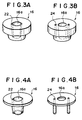
- the spaces Si and So may be communicated through only a pair of like grooves 22 as shown in Figure 3A or through a plurality of (e.g., two or four) through holes 24 formed away from the inner peripheral surface 16a of the lid member 16 as shown in Figure 3B.
- the diameter of each through hole may be, for instance, 0.2 to 1.0mm.
- the lid member 16 is formed of silicone rubber in the embodiment described above, the lid member 16 may be formed of inexpensive plastic.
- the plastic lid member 16 may comprise an annular collar portion and a tubular portion extending downward from the collar portion and semi-circular grooves 22 (e.g., 2 or 4) may be formed along the inner peripheral surface 16a of the tubular portion as shown in Figure 4A.
- the plastic lid member 16 may comprise an annular collar portion and columns (e.g., 2 or 4) extending downward from the collar portion away from the inner peripheral surface 16a of the lid member 16, and a through hole 24 may be formed in each of the columns to extend therethrough as shown in Figure 4B.
- the communicating passage is formed between the lower surface of the lid member 16 and the upper surface of the mouth 20a of the container 20 by one or more radial grooves formed in the lower surface of the lid member 16.
- the communicating passage is formed in the lid member 16
- the communicating passage may be formed in the tip body 14.
- the communicating passage is formed by one or more grooves 28 formed on the outer surface of the tip body 14 to extend in the longitudinal direction of the tip body 14 from above the upper surface of the lid member 16 to below the lower surface of the same.
- the outer surface (including the bottom surface) of the lower end portion 14b of the tip body 14 near the liquid intake/discharge port thereof be subjected to a water-repellent treatment or hydrophobicity treatment with silicone resin, fluorinated resin, fluorine-containing surface-active agent or the like. Since the tip body 14 is held at a constant height from the bottom of the container 20, the tip body 14 is dipped relatively deep into the reference liquid L when the container 20 contains a large amount of reference liquid L. The water-repellent treatment or hydrophobicity treatment prevents the reference liquid L from adhering to the outer surface of the tip body 14 and being carried out.
- the shape of the lid member 16 need not be limited to those described above but may be properly selected according the shape of the tip body 14 and/or the shape of the container 20.
- the container 20 contains reference liquid L by way of example, the present invention may be applied to containers containing therein various liquids such as sample liquids, reagent solutions and the like.
- the experiment was made in the following manner.
- the spotting tip 12 comprised a tip body 14 formed of polypropylene and a lid member 16 formed of silicone rubber.
- a container 20 containing therein reference liquid L was prepared and the lid and the inner plug on the container 20 were removed.
- the spotting tip 12 was inserted into the container 20 through the mouth 20a thereof and the upper open end of the tip body 14 was closed with a weight 32 of 200g so that the inside space Si and the outside space So of the container 20 were communicated only through the fine communicating passages (grooves 22).
- the experimental device was then caused to stand in a room which was kept at a temperature of 32 ⁇ 0.1°C and a relative humidity of 30 ⁇ 2% for 24 hours. Then reduction in the weight was measured and the evaporation loss was calculated.
- FUJI DRI-CHEM ELECTROLYTE REFERENCE FLUID ® (trade name) was employed as the reference liquid L.
- FUJI DRI-CHEM CLEAN TIPS ® (trade name) was used as the tip body 14.
- the tip was a pipette tip coated with silicone resin on the outer surface of the lower end portion (water-repellent treatment).
- Containers 20 each containing reference liquid L of 6g and containers 20 each containing reference liquid L of 8g were prepared.
- test numbers #1 to #6 were for containers containing reference liquid L of 6g and test numbers #7 to #12 were for containers containing reference liquid L of 8g.
- Figure 9A is for the containers containing reference liquid L of 6g and Figure 9B is for the containers containing reference liquid L of 8g.
- the evaporation loss increased substantially in proportional to the area of the communicating passages and the rate of increase was larger in the containers containing less liquid.
- the evaporation loss is not more than about 1% after elapse of 24 hours, it may be considered that concentration of the liquid is well prevented. In this regard, the evaporation loss was not more than 0.6% in any of the test samples, which proved the effect of the invention.
- the reference liquid L did not flow back into the spotting tip 12 or the nozzle 18 and the evaporation loss was not more than 0.7% with any of the spotting tips.
Abstract
Description
- This invention relates to a spotting tip which is fitted on a liquid sucking nozzle for sucking liquid in a container, and more particularly to a spotting tip which sucks liquid to be subjected to a biochemical analysis or the like and spots the liquid on an element, device or the like for biochemical analysis.
- Quantitative analysis of a particular chemical component in a sample liquid is commonly carried out in various industrial fields. For example, there have been known various methods of potentiometrically analyzing an activity (or concentration) of a particular ionic substances contained in a spotted sample liquid such as liquors, beverages, city water or a body fluid such as blood, urine or saliva. Ionic activity measuring devices for measuring an activity of an ionic substance in a spotted sample liquid are disclosed, for instance, in Japanese Unexamined Patent Publication Nos. 59(1984)-30055 and 6(1994)-66759, and U.S. Patent No. 4,437,973.
- Generally such an ionic activity measuring device includes at least a set of ion selective electrode pair each having an outermost layer composed of an ion selective layer which selectively responds to a particular ion such as Na, K, Cl or the like. The ion selective electrode pair are supported between an upper frame and a lower support frame, and a pair of liquid spotting holes are provided in the upper frame respectively opposed to the electrodes. A porous bridge which establishes an electrical connection between a sample liquid spotted to one of the spotting holes and a reference liquid spotted to the other spotting hole is provided in the upper frame. Preferably the porous bridge is formed of twisted yarn of fibers.
- In such an ionic activity measuring device, when a reference liquid containing therein an ionic substance whose ionic activity is known is spotted to one of the spotting holes and a sample liquid containing therein the ionic substance whose ionic activity is unknown is spotted to the other spotting hole, the liquids soak into porous liquid distributing members and reach the corresponding ion selective electrodes while the interfaces of the liquids are brought into an electrical contact with each other near the middle of the porous bridge. As a result, there is produced a potential difference between the electrodes according to the difference between the activity of the ionic substance in the sample liquid and that in the reference liquid. By measuring the potential difference, the activity of the ionic substance in the sample liquid can be determined on the basis of a calibration curve or a standard curve which has been determined in advance on the basis of Nernst equation.
- The ionic activity measuring device is very useful for analysis of aqueous sample liquid, especially for clinical analysis of a sample liquid from a human body such as blood since the ionic activity can be easily determined by only spotting droplets of the sample liquid and the reference liquid.
- When spotting the sample liquid and the reference liquid, the liquids are sucked in different spotting tips and dropped onto the respective spotting holes from the ends of the tips. Each tip is fitted on a liquid sucking nozzle and dipped into the sample liquid or the reference liquid and then the sample liquid or the reference liquid is sucked into the tip in a predetermined amount in response to a sucking operation of the liquid sucking nozzle and then held there. Then the tips on the sucking nozzles are moved to predetermined positions above the ionic activity measuring device and then discharge the sample liquid and the reference liquid onto the spotting holes in response to a discharging operation of the nozzles. The sample liquid and the reference liquid may be spotted either simultaneously or in sequence generally within 60 seconds.
- In the container containing the sample liquid or the reference liquid, when the mouth of the container through which the spotting tip is inserted into the container is kept open for a long time, there is a possibility of the liquid evaporating to change the concentrations of the components and spoiling.
- Accordingly conventionally the mouth of the container is normally covered with a lid and is opened only when the liquid therein is to be sucked. The lid is put on again immediately thereafter.
- However shutting and opening the mouth is very troublesome and puts an obstacle in automating the liquid sucking operation.
- In order to overcome the problem, we have proposed a novel tip in our Japanese Unexamined Patent Publication No. 7(1995)-80331. The tip is provided with a lid member which is brought into contact with the mouth of the container and closes the space between the tip and the edge of the mouth when the tip is inserted into the container to a predetermined depth. The tip is normally held in the container with the lid member in contact with the mouth except when the liquid in the container is to be spotted, whereby the container is held air-tight and the liquid in the container is suppressed from evaporating and diffusing outside.
- However when the tip was actually used, the liquid in the container flowed back into the tip and in extreme case even into the nozzle after the tip was held in the container for a long time. When such a back flow of the liquid occurs, the liquid cannot be spotted in an accurate amount due to liquid remaining in the tip or nozzle and there is a possibility of the concentration of the liquid changing.
- Though not clear, the reason why the back flow occurs is considered to be that when the temperature in the container is raised while the container is held air-tight by the lid member for a long time, gases including vapor expand and raise the liquid in the container into the tip or the nozzle.
- In view of the foregoing observations and description, the primary object of the present invention is to provide a spotting tip for aspirating and precision dispensing liquid which can minimize evaporation of the liquid in the container and at the same time can prevent back flow of the liquid into the tip or the nozzle.
- Based on the recognition that the back flow of the liquid in the container can be prevented if the pressure difference between the space inside of the container and the space outside of the same on opposite sides of the lid member can be nullified, the present invention accomplishes the above object by forming a fine communicating passage which communicates the inside and the outside of the container in at least one of the lid member and the tip body.
- That is, in accordance with the present invention, there is provided a spotting tip comprising a tip body which is fitted on the end of a nozzle of a liquid sucking means for sucking liquid contained in a container and inserted into the liquid in the container through a mouth of the container, and a lid member which is brought into contact with the mouth of the container and closes the space between the tip and the edge of the mouth when the tip is inserted into the container to a predetermined depth, the liquid sucking means operating to suck a predetermined amount of the liquid into the tip body with the tip body held in the liquid, wherein the improvement comprises
at least one fine communicating passage which is formed in at least one of the lid member and the tip body to communicate the inside and outside spaces of the container on opposite sides of the lid member. - The lid member may be formed integrally with the tip body. Otherwise the lid member may be formed separately from the tip body and attached thereto.
- The tip body and the lid member may be formed of any material so long as it does not modify nor deteriorate the liquid in the container. For example, the tip body may be formed of an organic polymer material such as polyethylene, polypropylene, fluoropolymer, silicone resin or the like. The lid member may be formed of an organic polymer material such as polyethylene, polypropylene, fluoropolymer, silicone resin or the like or a rubber material such as silicone rubber.
- The fine communicating passage may be of any shape and any size so long as it can nullify the pressure difference between the space inside of the container and the space outside of the same on opposite sides of the lid member without largely deteriorating the function of the lid member to suppress evaporation of the liquid in the container. Further a plurality of the fine communicating passages may be provided unless the function of the lid member to suppress evaporation of the liquid in the container is largely deteriorated. However, in order to enhance the function of the lid member, it is preferred that the communicating passage be long to a certain extent. Further when there is only one communicating passage, communication between the inside and outside spaces can be broken if the passage is blocked with foreign matter such as dust, fine cuttings of the lid member or the like or by accident. Accordingly preferably a plurality of the fine communicating passage are be provided.
- With the arrangement described above, the container can be held air-tight and the liquid in the container is suppressed from evaporating and diffusing outside the container by normally holding the tip body in the container with the lid member in contact with the mouth of the container, whereby the liquid is prevented from being concentrated . Further since the ingress of foreign matters is prevented, the liquid in the container can be prevented from being contaminated and spoiling. Accordingly, even in a biochemical analysis where a fine change in the concentration of the components gives rise to a problem, the accuracy of measurement can be held high.
- Further since the fine communicating passage equalizes the pressures inside and outside the container, the liquid in the container cannot flow into the tip body or the nozzle even if the tip body is held inside the liquid with the lid member in contact with the mouth of the container for a long time. Accordingly the liquid can be constantly spotted in an accurate amount and the change in the concentration of the liquid due to back flow can be prevented.
- Further since the mouth of the container is opened and closed by the spotting tip itself, necessity of putting on and off the lid as in the conventional system can be eliminated and the spotting operation is facilitated.
- It is preferred that the outer surface of the tip near the liquid intake/discharge port thereof be subjected to a water-repellent treatment or hydrophobicity treatment to prevent the liquid from adhering to the outer surface of the tip body to be carried out, whereby concentration of the liquid in the container is further prevented.
-
- Figure 1 is a cross-sectional view of a spotting tip in accordance with an embodiment of the present invention with the tip inserted into a container,
- Figure 2 is a perspective view of the spotting tip away from the container,
- Figures 3A, 3B, 4A and 4B are perspective views respectively showing modifications of the lid members employed in the spotting tip of the embodiment,
- Figures 5 and 6 are views similar to Figure 1 respectively showing modifications of the lid members employed in the spotting tip of the embodiment,
- Figure 7 is a cross-sectional view showing an experimental device which was employed in an experiment for proving the result of the invention,
- Figures 8A and 8B are plan views for illustrating the structures of the lid members employed in the experiment, and
- Figures 9A and 9B are graphs showing the result of the experiment.
- In Figures 1 and 2, a
spotting tip 12 in accordance with an embodiment of the present invention comprises atip body 14 which is shaped like a cone tapered downward and anannular lid member 16 fitted on thetip body 14 at an intermediate portion thereof. - The
spotting tip 12 is mounted on anozzle 18 of a liquid sucking means (not shown) by press-fitting theupper end portion 14a of thetip body 14 on thelower end portion 18a of thenozzle 18. An O-ring 30 is fitted on thelower end portion 18a of thenozzle 18 and is brought into close contact with the inner peripheral surface of thetip body 14, when theupper end portion 14a of thetip body 14 is fitted on thelower end portion 18a of thenozzle 18, to seal the space between the outer peripheral surface of thenozzle 18 and the inner peripheral surface of thetip body 14 in an air-tight fashion. - A reference liquid L is contained in a
container 20 having amouth 20a. With thespotting tip 12 on thenozzle 18, thetip body 14 is inserted into thecontainer 20 through themouth 20a so that thelower end portion 14b (having a diameter smaller than theupper end portion 14a) of thetip body 14 is dipped into the reference liquid L. When the reference liquid L is to be spotted, a predetermined amount of the reference liquid L is sucked into thetip body 14 of thespotting tip 12 through the opening at the end of thelower end portion 14b. - The
lid member 16 comprises a larger diameter upper portion and a smaller diameter lower portion which is tapered downward. When thetip body 14 is inserted into thecontainer 20 to a predetermined depth, the lower surface of the upper portion of thelid member 16 is brought into contact with the inner peripheral edge of themouth 20a of thecontainer 20 to shut the space between themouth 20a and thetip body 14. Thelid member 16 is formed of elastic silicone rubber so that the space between themouth 20a and thetip body 14 is surely shut. Fourgrooves 16a are formed in the innerperipheral surface 16a of thelid member 16 at intervals of 90° to extend through thelid member 16 in the longitudinal direction thereof. Thegrooves 16a form four fine communicating passages which communicate the space Si inside thecontainer 20 and the space So outside thecontainer 20 when the spottingtip 12 is inserted into thecontainer 20 so that thelid member 16 closes themouth 20a. Eachgroove 16a is semi-circular in cross-section and has a radius of 0.1 to 1.0mm (e.g., 0.5mm). - An
annular shoulder 14c is formed on the outer peripheral surface of thetip body 14 at an intermediate portion thereof. Theshoulder 14c is for limiting the position of thelid member 16 relative to thetip body 14 when thelid member 16 is fitted on the spottingtip 12 and has a width of about 0.3mm. Even when thetip body 14 is inserted into thelid member 16 until theshoulder 14c is brought into abutment against thelid member 16, thelid member 16 is held away from theshoulder 14c at a distance of about 0.5 to 1.0mm by virtue of the elasticity (spring back) of thelid member 16. Accordingly the fine communicating passages cannot be closed by theshoulder 14c. - As can be understood from the description above, the
container 20 can be held air-tight and the reference liquid L in thecontainer 20 is suppressed from evaporating and diffusing outside thecontainer 20 by normally holding thetip body 14 in thecontainer 20 with thelid member 14 in contact with themouth 20a of thecontainer 20 except when the liquid L is to be spotted, whereby the liquid L is prevented from being concentrated . Further since the ingress of foreign matters into thecontainer 20 is prevented, the liquid L in thecontainer 20 can be prevented from being contaminated and spoiling. Accordingly, even in a biochemical analysis where a fine change in the concentration of the components gives rise to a problem, the accuracy of measurement can be held high. - Further since the fine communicating passages formed by the
grooves 22 on the innerperipheral surface 16a of thelid member 16 communicate the inside space Si and the outside space So and equalize the pressures inside and outside the container, the liquid L in thecontainer 20 cannot flow into thetip body 14 or thenozzle 18 even if thetip body 14 is held inside the liquid L with thelid member 16 in contact with themouth 20a of thecontainer 20 for a long time. Accordingly the liquid L can be constantly spotted in an accurate amount and the change in the concentration of the liquid L due to back flow can be prevented. - In this particular embodiment, since the fine communicating passages are formed by
elongated grooves 22, even if the liquid L evaporates and enters the passages, all most all the vapor is condensed, whereby evaporation of the liquid L outside thecontainer 20 can be effectively prevented. - Thus in accordance with the embodiment described above, evaporation of the reference liquid L outside the
container 20 can be minimized and at the same time back flow of the reference liquid L into thetip body 14 or thenozzle 18 can be prevented. - Further since the
mouth 20a of thecontainer 20 is opened and closed by the spottingtip 12 itself, necessity of putting on and off the lid as in the conventional system can be eliminated and the spotting operation is facilitated. - Though, in the embodiment described above, the inside space Si and the outside space So of the
container 20 are communicated through the fine communicating passages formed by fourgrooves 22 which are formed in the innerperipheral surface 16a of thelid member 16 to extend through thelid member 16 in the longitudinal direction thereof and are semi-circular in cross-section, the spaces Si and So may be communicated through only a pair oflike grooves 22 as shown in Figure 3A or through a plurality of (e.g., two or four) throughholes 24 formed away from the innerperipheral surface 16a of thelid member 16 as shown in Figure 3B. In the latter case, the diameter of each through hole may be, for instance, 0.2 to 1.0mm. - Though the
lid member 16 is formed of silicone rubber in the embodiment described above, thelid member 16 may be formed of inexpensive plastic. In this case, theplastic lid member 16 may comprise an annular collar portion and a tubular portion extending downward from the collar portion and semi-circular grooves 22 (e.g., 2 or 4) may be formed along the innerperipheral surface 16a of the tubular portion as shown in Figure 4A. Further theplastic lid member 16 may comprise an annular collar portion and columns (e.g., 2 or 4) extending downward from the collar portion away from the innerperipheral surface 16a of thelid member 16, and a throughhole 24 may be formed in each of the columns to extend therethrough as shown in Figure 4B. - In another modification of the
lid member 16 shown in Figure 5, the communicating passage is formed between the lower surface of thelid member 16 and the upper surface of themouth 20a of thecontainer 20 by one or more radial grooves formed in the lower surface of thelid member 16. - Though in the embodiment and the modifications described above, the communicating passage is formed in the
lid member 16, the communicating passage may be formed in thetip body 14. For example, in the modification shown in Figure 6, the communicating passage is formed by one ormore grooves 28 formed on the outer surface of thetip body 14 to extend in the longitudinal direction of thetip body 14 from above the upper surface of thelid member 16 to below the lower surface of the same. - It is preferred that the outer surface (including the bottom surface) of the
lower end portion 14b of thetip body 14 near the liquid intake/discharge port thereof be subjected to a water-repellent treatment or hydrophobicity treatment with silicone resin, fluorinated resin, fluorine-containing surface-active agent or the like. Since thetip body 14 is held at a constant height from the bottom of thecontainer 20, thetip body 14 is dipped relatively deep into the reference liquid L when thecontainer 20 contains a large amount of reference liquid L. The water-repellent treatment or hydrophobicity treatment prevents the reference liquid L from adhering to the outer surface of thetip body 14 and being carried out. - The shape of the
lid member 16 need not be limited to those described above but may be properly selected according the shape of thetip body 14 and/or the shape of thecontainer 20. - Though in the embodiment described above, the
container 20 contains reference liquid L by way of example, the present invention may be applied to containers containing therein various liquids such as sample liquids, reagent solutions and the like. - In order to prove the result of the invention, an experiment was made using an experimental device shown in Figure 7. In the experiment, the evaporation loss of the reference liquid L in the
container 20 was measured. - The experiment was made in the following manner. The spotting
tip 12 comprised atip body 14 formed of polypropylene and alid member 16 formed of silicone rubber. Acontainer 20 containing therein reference liquid L was prepared and the lid and the inner plug on thecontainer 20 were removed. The spottingtip 12 was inserted into thecontainer 20 through themouth 20a thereof and the upper open end of thetip body 14 was closed with aweight 32 of 200g so that the inside space Si and the outside space So of thecontainer 20 were communicated only through the fine communicating passages (grooves 22). - The experimental device was then caused to stand in a room which was kept at a temperature of 32±0.1°C and a relative humidity of 30±2% for 24 hours. Then reduction in the weight was measured and the evaporation loss was calculated.
- FUJI DRI-CHEM ELECTROLYTE REFERENCE FLUID ® (trade name) was employed as the reference liquid L. FUJI DRI-CHEM CLEAN TIPS ® (trade name) was used as the
tip body 14. The tip was a pipette tip coated with silicone resin on the outer surface of the lower end portion (water-repellent treatment). -
Containers 20 each containing reference liquid L of 6g andcontainers 20 each containing reference liquid L of 8g were prepared. - As the
lid members 16, those having foursemi-circular grooves 22 as shown in Figure 8A, those having twosemi-circular grooves 22, those having four circular throughholes 24 as shown in Figure 8B and those having two circular throughholes 24 were prepared. The radii or diameters of the grooves or holes were as shown in the following table.Table test # #1 & 7 #2 & 8 #3 & 9 #4 & 10 #5 & 11 #6 & 12 R or φ R0.1mm R0.25mm R0.8mm φ0.2mm φ0.5mm φ1.0mm area 1.32mm² 1.88mm² 2.4mm² 0.52mm² 0.52mm² 1.11mm² number 4 4 2 4 2 2 % evp. 6g 0.3817 0.3887 0.5765 0.2209 0.1819 0.3474 8g 0.2760 0.2820 0.3650 0.1660 0.1390 0.2410 - In the table, "area" means measured areas of the grooves or holes and "number" means the number of the grooves or holes. Test numbers #1 to #6 were for containers containing reference liquid L of 6g and test numbers #7 to #12 were for containers containing reference liquid L of 8g.
- The result of the experiment were as shown in the above table and Figures 9A and 9B. Figure 9A is for the containers containing reference liquid L of 6g and Figure 9B is for the containers containing reference liquid L of 8g.
- As can be understood from the table and Figures 9A and 9B, the evaporation loss increased substantially in proportional to the area of the communicating passages and the rate of increase was larger in the containers containing less liquid.
- When the evaporation loss is not more than about 1% after elapse of 24 hours, it may be considered that concentration of the liquid is well prevented. In this regard, the evaporation loss was not more than 0.6% in any of the test samples, which proved the effect of the invention.
- Employing the spotting tips employed in tests No.1 to No.12 in an electrolyte measuring system, measurement of electrolyte was repeated, and the evaporation loss was measured and occurrence of back flow was observed.
- The reference liquid L did not flow back into the spotting
tip 12 or thenozzle 18 and the evaporation loss was not more than 0.7% with any of the spotting tips.
Claims (6)
- A spotting tip comprising a tip body which is fitted on the end of a nozzle of a liquid sucking means for sucking liquid contained in a container and inserted into the liquid in the container through a mouth of the container, and a lid member which is brought into contact with the mouth of the container and closes the space between the tip and the edge of the mouth when the tip is inserted into the container to a predetermined depth, the liquid sucking means operating to suck a predetermined amount of the liquid into the tip body with the tip body held in the liquid, wherein the improvement comprises
at least one fine communicating passage which is formed in at least one of the lid member and the tip body to communicate the inside and outside spaces of the container on opposite sides of the lid member. - A spotting tip as defined in Claim 1 in which a plurality of the fine communicating passages are provided
- A spotting tip as defined in Claim 1 in which said communicating passage is in the form of a groove formed in the inner peripheral surface of the lid member to extend from the lower surface of the lid member to the upper surface of the same.
- A spotting tip as defined in Claim 1 in which said communicating passage is in the form of a through hole formed in the lid member to extend from the lower surface of the lid member to the upper surface of the same.
- A spotting tip as defined in Claim 1 in which said communicating passage is in the form of a groove formed in the lower surface of the lid member to extend in a radial direction of the lid member.
- A spotting tip as defined in Claim 1 in which said communicating passage is in the form of a groove which is formed on the outer surface of the tip body in the longitudinal direction thereof from the lower surface of the lid member to the upper surface of the same.
Applications Claiming Priority (3)
| Application Number | Priority Date | Filing Date | Title |
|---|---|---|---|
| JP22176294 | 1994-09-16 | ||
| JP22176294A JP3387649B2 (en) | 1994-09-16 | 1994-09-16 | Spotted tip |
| JP221762/94 | 1994-09-16 |
Publications (2)
| Publication Number | Publication Date |
|---|---|
| EP0701865A1 true EP0701865A1 (en) | 1996-03-20 |
| EP0701865B1 EP0701865B1 (en) | 2001-12-05 |
Family
ID=16771808
Family Applications (1)
| Application Number | Title | Priority Date | Filing Date |
|---|---|---|---|
| EP95114301A Expired - Lifetime EP0701865B1 (en) | 1994-09-16 | 1995-09-12 | Spotting tip |
Country Status (4)
| Country | Link |
|---|---|
| US (1) | US5874048A (en) |
| EP (1) | EP0701865B1 (en) |
| JP (1) | JP3387649B2 (en) |
| DE (1) | DE69524324T2 (en) |
Cited By (15)
| Publication number | Priority date | Publication date | Assignee | Title |
|---|---|---|---|---|
| WO1997048491A1 (en) * | 1996-06-20 | 1997-12-24 | Hamilton Bonaduz Ag | Method for achieving chemical, in particular biochemical reactions and pipette tip with reaction vessel and with optional additional receiving component for said pipette tip |
| EP0849584A2 (en) * | 1996-12-19 | 1998-06-24 | Dade Behring Marburg GmbH | Apparatus (cuvette) for receiving and storing liquids and for performing optical measurements |
| EP0856298A1 (en) * | 1997-01-31 | 1998-08-05 | Instruments De Medecine Veterinaire | Filler pipe for biological liquid containers, in particular for artificial insemination |
| FR2762910A1 (en) * | 1997-05-05 | 1998-11-06 | Bio Merieux | DEVICE FOR TRANSFERRING A LIQUID |
| WO1999043434A1 (en) | 1998-02-27 | 1999-09-02 | Ventana Medical Systems, Inc. | System and method of aspirating and dispensing reagent |
| GB2346096A (en) * | 1999-01-29 | 2000-08-02 | Jenoptik Jena Gmbh | Pipette tip with end seal |
| DE10013511A1 (en) * | 2000-03-20 | 2001-10-11 | Brand Gmbh & Co Kg | Multiple channel pipetting arrangement used for microtitration plates has pipette shafts each having a sealing receiver on the upper end with a plunger seal arranged in it |
| US6305585B1 (en) | 1997-01-31 | 2001-10-23 | Instruments De Medecine Veterinaire | Filler nozzle for packaging for biological liquids, in particular for artificial insemination |
| WO2002039916A1 (en) * | 2000-11-17 | 2002-05-23 | Ilia Borisovitch Izvoztchikov | Medium dispenser for enclosing histological and biological samples |
| US7396508B1 (en) | 2000-07-12 | 2008-07-08 | Ventana Medical Systems, Inc. | Automated molecular pathology apparatus having independent slide heaters |
| WO2009058952A1 (en) * | 2007-11-02 | 2009-05-07 | Viaflo Corporation | Locking pipette tip and mounting shaft |
| US8277757B2 (en) | 2009-09-29 | 2012-10-02 | Integra Biosciences Corp. | Pipette tip mounting shaft |
| WO2014140640A1 (en) * | 2013-03-15 | 2014-09-18 | Diagnostics For The Real World, Ltd | Apparatus and method for automated sample preparation and adaptor for use in the apparatus |
| US10143623B2 (en) | 2014-10-31 | 2018-12-04 | Yoshino Kogyosho Co., Ltd. | Syringe container |
| WO2020127897A1 (en) * | 2018-12-20 | 2020-06-25 | Tecan Trading Ag | Tip cup |
Families Citing this family (27)
| Publication number | Priority date | Publication date | Assignee | Title |
|---|---|---|---|---|
| US6056135A (en) * | 1997-12-16 | 2000-05-02 | Widman; Michael L. | Liquid transfer device to facilitate removal of liquid from a container by a syringe |
| US6431476B1 (en) | 1999-12-21 | 2002-08-13 | Cepheid | Apparatus and method for rapid ultrasonic disruption of cells or viruses |
| JP3670503B2 (en) * | 1999-01-12 | 2005-07-13 | 株式会社日立製作所 | Dispensing device |
| DE19917375C2 (en) | 1999-04-16 | 2001-09-27 | Hamilton Bonaduz Ag Bonaduz | Pipetting unit |
| ATE427159T1 (en) * | 1999-05-14 | 2009-04-15 | Gen Probe Inc | FLUID TRANSFER DEVICE FOR USE WITH PENETRABLE CAP |
| US6716396B1 (en) * | 1999-05-14 | 2004-04-06 | Gen-Probe Incorporated | Penetrable cap |
| EP1101532B1 (en) * | 1999-10-22 | 2006-09-20 | Ngk Insulators, Ltd. | Dispenser for producing DNA microarray |
| DE19963032A1 (en) * | 1999-12-24 | 2001-06-28 | Roche Diagnostics Gmbh | System for processing samples in a multi-chamber arrangement |
| US20080148872A1 (en) * | 2000-05-12 | 2008-06-26 | Gen-Probe Incorporated | Method for accessing the contents of an assembly |
| US20040110301A1 (en) * | 2000-11-17 | 2004-06-10 | Neilson Andy C | Apparatus and methods for measuring reaction byproducts |
| US6821787B2 (en) * | 2000-11-17 | 2004-11-23 | Thermogenic Imaging, Inc. | Apparatus and methods for infrared calorimetric measurements |
| US20020132360A1 (en) * | 2000-11-17 | 2002-09-19 | Flir Systems Boston, Inc. | Apparatus and methods for infrared calorimetric measurements |
| DE60214829T2 (en) | 2001-03-09 | 2007-04-26 | Gen-Probe Inc., San Diego | PUNCHABLE CLOSURE |
| US6783737B2 (en) * | 2002-01-25 | 2004-08-31 | Bristol-Myers Squibb Company | High pressure chemistry reactor |
| JP3648487B2 (en) * | 2002-03-01 | 2005-05-18 | アロカ株式会社 | Nozzle tip for dispensing equipment |
| US7378057B2 (en) * | 2002-04-01 | 2008-05-27 | Ortho-Clinical Diagnostics, Inc. | Evaporation control for a fluid supply |
| US20040191923A1 (en) * | 2003-03-31 | 2004-09-30 | Tomasso David Angelo | Test element holder with a probe guide for an analyzer |
| US20050101025A1 (en) * | 2003-11-12 | 2005-05-12 | Ho Winston Z. | Apparatus for proteins and nucleic acids analysis |
| WO2007103691A2 (en) * | 2006-03-01 | 2007-09-13 | James Benjamin Hobbins | Modular reinforced soft bait lure system |
| US7722822B2 (en) * | 2006-03-23 | 2010-05-25 | Agilent Technologies, Inc. | Sample tube and vial processing system, and method for processing the sample |
| US8387811B2 (en) | 2007-04-16 | 2013-03-05 | Bd Diagnostics | Pierceable cap having piercing extensions |
| US8387810B2 (en) * | 2007-04-16 | 2013-03-05 | Becton, Dickinson And Company | Pierceable cap having piercing extensions for a sample container |
| US8480645B1 (en) * | 2008-08-22 | 2013-07-09 | Sambhu N. Choudhury | Multi-dose device for insertion into a vial and method of using the same |
| DE102010031240A1 (en) * | 2010-07-12 | 2012-01-12 | Hamilton Bonaduz Ag | Pipette tip with hydrophobic surface formation |
| JP2015175837A (en) * | 2014-03-18 | 2015-10-05 | ソニー株式会社 | Plate-like member for pipette tips, pipette tip, liquid agitation kit and liquid agitation apparatus |
| CN110582260B (en) * | 2017-05-05 | 2023-03-28 | 豪夫迈·罗氏有限公司 | Pharmaceutical preparation kit and method for preparing a medicament |
| CN113262832B (en) * | 2021-05-17 | 2022-04-19 | 睿科集团(厦门)股份有限公司 | Compatible sample introduction base rod structure |
Citations (10)
| Publication number | Priority date | Publication date | Assignee | Title |
|---|---|---|---|---|
| US1920335A (en) * | 1931-10-06 | 1933-08-01 | Edwin C Wood | Bottle stopping liquid lifter and dispenser |
| JPS5930055A (en) | 1982-08-13 | 1984-02-17 | Fuji Photo Film Co Ltd | Ion activity measuring apparatus |
| US4437973A (en) | 1982-04-05 | 1984-03-20 | Hri, Inc. | Coal hydrogenation process with direct coal feed and improved residuum conversion |
| US4648519A (en) * | 1986-04-28 | 1987-03-10 | Sunbeam Plastics Corporation | Vented closure |
| EP0331057A2 (en) * | 1988-02-29 | 1989-09-06 | Pharmacia- Eni Diagnostics, Inc. | Automatic reagent dispenser |
| DE4011584A1 (en) * | 1989-04-12 | 1990-10-18 | Olympus Optical Co | AUTOMATIC CHEMICAL ANALYZER |
| EP0504697A1 (en) * | 1991-03-19 | 1992-09-23 | F. Hoffmann-La Roche Ag | Reagent container closure |
| JPH0666759A (en) | 1992-08-19 | 1994-03-11 | Fuji Photo Film Co Ltd | Ion selecting electrode for analyzing potassium ion |
| JPH06182234A (en) * | 1992-12-22 | 1994-07-05 | Aloka Co Ltd | Disposable tip |
| JPH0780331A (en) * | 1993-09-14 | 1995-03-28 | Fuji Photo Film Co Ltd | Spot sticking tip and liquid concentration preventive method using the same |
Family Cites Families (12)
| Publication number | Priority date | Publication date | Assignee | Title |
|---|---|---|---|---|
| US4210255A (en) * | 1978-06-30 | 1980-07-01 | The Continental Group, Inc. | Self-venting end unit for pressure packaging |
| US4478095A (en) * | 1981-03-09 | 1984-10-23 | Spectra-Physics, Inc. | Autosampler mechanism |
| US4713974A (en) * | 1986-04-18 | 1987-12-22 | Varian Associates, Inc./Scientific Systems, Inc. | Autosampler |
| US4787898A (en) * | 1987-05-12 | 1988-11-29 | Burron Medical Inc. | Vented needle with sideport |
| JPH03131351A (en) * | 1989-10-16 | 1991-06-04 | Fuji Photo Film Co Ltd | Pipette tip subjected to water-repellent treatment |
| US5038958A (en) * | 1990-03-02 | 1991-08-13 | Norfolk Scientific, Inc. | Vented microscale centrifuge tube |
| US5036992A (en) * | 1990-03-27 | 1991-08-06 | Mouchawar Marvin L | Medicine vial cap for needleless syringe |
| US5078970A (en) * | 1990-06-28 | 1992-01-07 | Belona Laboratory Supplies And Development, Inc. | Apparatus for withdrawing a liquid sample from a sample vessel and transferring it |
| CA2046813A1 (en) * | 1990-10-02 | 1992-04-03 | Ueli Stettler | Apparatus for introducing pipetting inserts through sample cup closures |
| US5188628A (en) * | 1990-11-06 | 1993-02-23 | Sandoz Ltd. | Closure device for enteral fluid containers |
| US5483843A (en) * | 1992-06-01 | 1996-01-16 | Thermo Separation Products Inc. | Transport apparatus |
| US5232109A (en) * | 1992-06-02 | 1993-08-03 | Sterling Winthrop Inc. | Double-seal stopper for parenteral bottle |
-
1994
- 1994-09-16 JP JP22176294A patent/JP3387649B2/en not_active Expired - Fee Related
-
1995
- 1995-09-12 DE DE69524324T patent/DE69524324T2/en not_active Expired - Fee Related
- 1995-09-12 EP EP95114301A patent/EP0701865B1/en not_active Expired - Lifetime
-
1997
- 1997-08-04 US US08/906,006 patent/US5874048A/en not_active Expired - Fee Related
Patent Citations (10)
| Publication number | Priority date | Publication date | Assignee | Title |
|---|---|---|---|---|
| US1920335A (en) * | 1931-10-06 | 1933-08-01 | Edwin C Wood | Bottle stopping liquid lifter and dispenser |
| US4437973A (en) | 1982-04-05 | 1984-03-20 | Hri, Inc. | Coal hydrogenation process with direct coal feed and improved residuum conversion |
| JPS5930055A (en) | 1982-08-13 | 1984-02-17 | Fuji Photo Film Co Ltd | Ion activity measuring apparatus |
| US4648519A (en) * | 1986-04-28 | 1987-03-10 | Sunbeam Plastics Corporation | Vented closure |
| EP0331057A2 (en) * | 1988-02-29 | 1989-09-06 | Pharmacia- Eni Diagnostics, Inc. | Automatic reagent dispenser |
| DE4011584A1 (en) * | 1989-04-12 | 1990-10-18 | Olympus Optical Co | AUTOMATIC CHEMICAL ANALYZER |
| EP0504697A1 (en) * | 1991-03-19 | 1992-09-23 | F. Hoffmann-La Roche Ag | Reagent container closure |
| JPH0666759A (en) | 1992-08-19 | 1994-03-11 | Fuji Photo Film Co Ltd | Ion selecting electrode for analyzing potassium ion |
| JPH06182234A (en) * | 1992-12-22 | 1994-07-05 | Aloka Co Ltd | Disposable tip |
| JPH0780331A (en) * | 1993-09-14 | 1995-03-28 | Fuji Photo Film Co Ltd | Spot sticking tip and liquid concentration preventive method using the same |
Non-Patent Citations (2)
| Title |
|---|
| PATENT ABSTRACTS OF JAPAN vol. 018, no. 525 (C - 1257) 5 October 1994 (1994-10-05) * |
| PATENT ABSTRACTS OF JAPAN vol. 950, no. 003 * |
Cited By (31)
| Publication number | Priority date | Publication date | Assignee | Title |
|---|---|---|---|---|
| WO1997048491A1 (en) * | 1996-06-20 | 1997-12-24 | Hamilton Bonaduz Ag | Method for achieving chemical, in particular biochemical reactions and pipette tip with reaction vessel and with optional additional receiving component for said pipette tip |
| US6214626B1 (en) | 1996-12-19 | 2001-04-10 | Dade Behring Marburg Gmbh | Apparatus (cuvette) for taking up and storing liquids and for carrying out optical measurements |
| EP0849584A2 (en) * | 1996-12-19 | 1998-06-24 | Dade Behring Marburg GmbH | Apparatus (cuvette) for receiving and storing liquids and for performing optical measurements |
| EP0849584A3 (en) * | 1996-12-19 | 1999-06-16 | Dade Behring Marburg GmbH | Apparatus (cuvette) for receiving and storing liquids and for performing optical measurements |
| EP0856298A1 (en) * | 1997-01-31 | 1998-08-05 | Instruments De Medecine Veterinaire | Filler pipe for biological liquid containers, in particular for artificial insemination |
| FR2758973A1 (en) * | 1997-01-31 | 1998-08-07 | Instr Medecine Veterinaire | FILLING TIP FOR BIOLOGICAL LIQUID PACKAGING ELEMENTS, IN PARTICULAR FOR ARTIFICIAL INSEMINATION |
| US6305585B1 (en) | 1997-01-31 | 2001-10-23 | Instruments De Medecine Veterinaire | Filler nozzle for packaging for biological liquids, in particular for artificial insemination |
| FR2762910A1 (en) * | 1997-05-05 | 1998-11-06 | Bio Merieux | DEVICE FOR TRANSFERRING A LIQUID |
| WO1998050155A1 (en) * | 1997-05-05 | 1998-11-12 | Bio Merieux | Liquid transferring device |
| AU721005B2 (en) * | 1997-05-05 | 2000-06-22 | Bio Merieux | Liquid-transferring device |
| US6263743B1 (en) | 1997-05-05 | 2001-07-24 | Bio Merieux | Liquid transferring device |
| WO1999043434A1 (en) | 1998-02-27 | 1999-09-02 | Ventana Medical Systems, Inc. | System and method of aspirating and dispensing reagent |
| EP1056541A1 (en) * | 1998-02-27 | 2000-12-06 | Ventana Medical Systems, Inc. | System and method of aspirating and dispensing reagent |
| EP1056541A4 (en) * | 1998-02-27 | 2005-11-30 | Ventana Med Syst Inc | System and method of aspirating and dispensing reagent |
| EP2284543A3 (en) * | 1998-02-27 | 2015-05-27 | Ventana Medical Systems, Inc. | System and method of aspirating and dispensing reagent |
| GB2346096A (en) * | 1999-01-29 | 2000-08-02 | Jenoptik Jena Gmbh | Pipette tip with end seal |
| DE10013511A1 (en) * | 2000-03-20 | 2001-10-11 | Brand Gmbh & Co Kg | Multiple channel pipetting arrangement used for microtitration plates has pipette shafts each having a sealing receiver on the upper end with a plunger seal arranged in it |
| US6627160B2 (en) | 2000-03-20 | 2003-09-30 | Brand Gmbh + Co. Kg | Multiple channel pipetting device |
| US7396508B1 (en) | 2000-07-12 | 2008-07-08 | Ventana Medical Systems, Inc. | Automated molecular pathology apparatus having independent slide heaters |
| WO2002039916A1 (en) * | 2000-11-17 | 2002-05-23 | Ilia Borisovitch Izvoztchikov | Medium dispenser for enclosing histological and biological samples |
| US7662344B2 (en) | 2006-10-24 | 2010-02-16 | Viaflo Corporation | Locking pipette tip and mounting shaft |
| US8501118B2 (en) | 2006-10-24 | 2013-08-06 | Integra Biosciences Corp. | Disposable pipette tip |
| US8877513B2 (en) | 2006-10-24 | 2014-11-04 | Integra Biosciences Ag | Method of using a disposable pipette tip |
| US9333500B2 (en) | 2006-10-24 | 2016-05-10 | Integra Biosciences Ag | Locking pipette tip and mounting shaft in hand-held manual pipette |
| WO2009058952A1 (en) * | 2007-11-02 | 2009-05-07 | Viaflo Corporation | Locking pipette tip and mounting shaft |
| US8277757B2 (en) | 2009-09-29 | 2012-10-02 | Integra Biosciences Corp. | Pipette tip mounting shaft |
| WO2014140640A1 (en) * | 2013-03-15 | 2014-09-18 | Diagnostics For The Real World, Ltd | Apparatus and method for automated sample preparation and adaptor for use in the apparatus |
| US10184950B2 (en) | 2013-03-15 | 2019-01-22 | Diagnostics For The Real World, Ltd | HIV viral load testing |
| US10330694B2 (en) | 2013-03-15 | 2019-06-25 | Diagnostics For The Real World, Ltd | Apparatus and method for automated sample preparation and adaptor for use in the apparatus |
| US10143623B2 (en) | 2014-10-31 | 2018-12-04 | Yoshino Kogyosho Co., Ltd. | Syringe container |
| WO2020127897A1 (en) * | 2018-12-20 | 2020-06-25 | Tecan Trading Ag | Tip cup |
Also Published As
| Publication number | Publication date |
|---|---|
| JP3387649B2 (en) | 2003-03-17 |
| JPH0884934A (en) | 1996-04-02 |
| DE69524324T2 (en) | 2002-07-18 |
| DE69524324D1 (en) | 2002-01-17 |
| EP0701865B1 (en) | 2001-12-05 |
| US5874048A (en) | 1999-02-23 |
Similar Documents
| Publication | Publication Date | Title |
|---|---|---|
| EP0701865A1 (en) | Spotting tip | |
| US5496523A (en) | Filtered micropipette tip for high/low volume pipettors | |
| JP2790359B2 (en) | Dilution and mixing cartridges | |
| US5366902A (en) | Collection and display device | |
| KR101009447B1 (en) | Device for sampling and preprocessing biological fluids and method thereof | |
| AU742823B2 (en) | Capillary active test element having an intermediate layer situated between the support and the covering | |
| US5091153A (en) | Chemical analysis test device | |
| JP4811267B2 (en) | Microchip and analytical device using the same | |
| EP1206692B1 (en) | Particle characterisation apparatus | |
| JPH07148441A (en) | Pipette device for preventing contamination caused by aerosol and excessive suction | |
| WO1999041147A1 (en) | Capillary fill device with improved fluid delivery | |
| US4952516A (en) | Self-venting diagnostic test device | |
| CA2040920C (en) | Capillary inoculator and assembly for inoculating multiple test sites and method of inoculation test sites therewith | |
| US20090101681A1 (en) | Liquid Dispensing Tip With Reservoir | |
| JP4520468B2 (en) | Coated test element | |
| US4461181A (en) | Control for sample volume metering apparatus | |
| US4789435A (en) | Method and device of measuring ion activity | |
| JPS58140635A (en) | Liquid transfer and distirbution apparatus and measuring instrument of ion activity | |
| EP1490176B1 (en) | Bottle with evaporation limitation | |
| JP2668815B2 (en) | Transport collection container | |
| EP0295069B1 (en) | Diagnostic test device | |
| EP0023157B1 (en) | Liquid transport device | |
| US5389338A (en) | Apparatus for dry chemical analysis of fluids | |
| JP3323294B2 (en) | Spotting tip and liquid concentration preventing method using the spotting tip | |
| JP3425829B2 (en) | Sample suction and discharge method |
Legal Events
| Date | Code | Title | Description |
|---|---|---|---|
| PUAI | Public reference made under article 153(3) epc to a published international application that has entered the european phase |
Free format text: ORIGINAL CODE: 0009012 |
|
| AK | Designated contracting states |
Kind code of ref document: A1 Designated state(s): DE FR GB |
|
| 17P | Request for examination filed |
Effective date: 19960827 |
|
| 17Q | First examination report despatched |
Effective date: 19981223 |
|
| GRAG | Despatch of communication of intention to grant |
Free format text: ORIGINAL CODE: EPIDOS AGRA |
|
| GRAG | Despatch of communication of intention to grant |
Free format text: ORIGINAL CODE: EPIDOS AGRA |
|
| GRAH | Despatch of communication of intention to grant a patent |
Free format text: ORIGINAL CODE: EPIDOS IGRA |
|
| GRAH | Despatch of communication of intention to grant a patent |
Free format text: ORIGINAL CODE: EPIDOS IGRA |
|
| GRAA | (expected) grant |
Free format text: ORIGINAL CODE: 0009210 |
|
| AK | Designated contracting states |
Kind code of ref document: B1 Designated state(s): DE FR GB |
|
| REG | Reference to a national code |
Ref country code: GB Ref legal event code: IF02 |
|
| REF | Corresponds to: |
Ref document number: 69524324 Country of ref document: DE Date of ref document: 20020117 |
|
| ET | Fr: translation filed | ||
| PLBE | No opposition filed within time limit |
Free format text: ORIGINAL CODE: 0009261 |
|
| STAA | Information on the status of an ep patent application or granted ep patent |
Free format text: STATUS: NO OPPOSITION FILED WITHIN TIME LIMIT |
|
| 26N | No opposition filed | ||
| REG | Reference to a national code |
Ref country code: FR Ref legal event code: TP Ref country code: FR Ref legal event code: CD |
|
| PGFP | Annual fee paid to national office [announced via postgrant information from national office to epo] |
Ref country code: GB Payment date: 20070926 Year of fee payment: 13 |
|
| PGFP | Annual fee paid to national office [announced via postgrant information from national office to epo] |
Ref country code: DE Payment date: 20071031 Year of fee payment: 13 |
|
| PGFP | Annual fee paid to national office [announced via postgrant information from national office to epo] |
Ref country code: FR Payment date: 20070917 Year of fee payment: 13 |
|
| GBPC | Gb: european patent ceased through non-payment of renewal fee |
Effective date: 20080912 |
|
| REG | Reference to a national code |
Ref country code: FR Ref legal event code: ST Effective date: 20090529 |
|
| PG25 | Lapsed in a contracting state [announced via postgrant information from national office to epo] |
Ref country code: DE Free format text: LAPSE BECAUSE OF NON-PAYMENT OF DUE FEES Effective date: 20090401 |
|
| PG25 | Lapsed in a contracting state [announced via postgrant information from national office to epo] |
Ref country code: FR Free format text: LAPSE BECAUSE OF NON-PAYMENT OF DUE FEES Effective date: 20080930 |
|
| PG25 | Lapsed in a contracting state [announced via postgrant information from national office to epo] |
Ref country code: GB Free format text: LAPSE BECAUSE OF NON-PAYMENT OF DUE FEES Effective date: 20080912 |