EP0701838A2 - Atrial defibrillator having patient activated modality - Google Patents
Atrial defibrillator having patient activated modality Download PDFInfo
- Publication number
- EP0701838A2 EP0701838A2 EP95250216A EP95250216A EP0701838A2 EP 0701838 A2 EP0701838 A2 EP 0701838A2 EP 95250216 A EP95250216 A EP 95250216A EP 95250216 A EP95250216 A EP 95250216A EP 0701838 A2 EP0701838 A2 EP 0701838A2
- Authority
- EP
- European Patent Office
- Prior art keywords
- sequence
- patient
- intervention
- atrial
- atrial fibrillation
- Prior art date
- Legal status (The legal status is an assumption and is not a legal conclusion. Google has not performed a legal analysis and makes no representation as to the accuracy of the status listed.)
- Withdrawn
Links
Images

Classifications
-
- A—HUMAN NECESSITIES
- A61—MEDICAL OR VETERINARY SCIENCE; HYGIENE
- A61N—ELECTROTHERAPY; MAGNETOTHERAPY; RADIATION THERAPY; ULTRASOUND THERAPY
- A61N1/00—Electrotherapy; Circuits therefor
- A61N1/02—Details
- A61N1/04—Electrodes
- A61N1/05—Electrodes for implantation or insertion into the body, e.g. heart electrode
- A61N1/056—Transvascular endocardial electrode systems
- A61N1/0563—Transvascular endocardial electrode systems specially adapted for defibrillation or cardioversion
-
- A—HUMAN NECESSITIES
- A61—MEDICAL OR VETERINARY SCIENCE; HYGIENE
- A61N—ELECTROTHERAPY; MAGNETOTHERAPY; RADIATION THERAPY; ULTRASOUND THERAPY
- A61N1/00—Electrotherapy; Circuits therefor
- A61N1/18—Applying electric currents by contact electrodes
- A61N1/32—Applying electric currents by contact electrodes alternating or intermittent currents
- A61N1/38—Applying electric currents by contact electrodes alternating or intermittent currents for producing shock effects
- A61N1/39—Heart defibrillators
- A61N1/3918—Heart defibrillators characterised by shock pathway, e.g. by electrode configuration
-
- A—HUMAN NECESSITIES
- A61—MEDICAL OR VETERINARY SCIENCE; HYGIENE
- A61N—ELECTROTHERAPY; MAGNETOTHERAPY; RADIATION THERAPY; ULTRASOUND THERAPY
- A61N1/00—Electrotherapy; Circuits therefor
- A61N1/18—Applying electric currents by contact electrodes
- A61N1/32—Applying electric currents by contact electrodes alternating or intermittent currents
- A61N1/38—Applying electric currents by contact electrodes alternating or intermittent currents for producing shock effects
- A61N1/39—Heart defibrillators
- A61N1/3956—Implantable devices for applying electric shocks to the heart, e.g. for cardioversion
- A61N1/3962—Implantable devices for applying electric shocks to the heart, e.g. for cardioversion in combination with another heart therapy
- A61N1/39622—Pacing therapy
-
- A—HUMAN NECESSITIES
- A61—MEDICAL OR VETERINARY SCIENCE; HYGIENE
- A61N—ELECTROTHERAPY; MAGNETOTHERAPY; RADIATION THERAPY; ULTRASOUND THERAPY
- A61N1/00—Electrotherapy; Circuits therefor
- A61N1/18—Applying electric currents by contact electrodes
- A61N1/32—Applying electric currents by contact electrodes alternating or intermittent currents
- A61N1/38—Applying electric currents by contact electrodes alternating or intermittent currents for producing shock effects
- A61N1/39—Heart defibrillators
- A61N1/395—Heart defibrillators for treating atrial fibrillation
-
- A—HUMAN NECESSITIES
- A61—MEDICAL OR VETERINARY SCIENCE; HYGIENE
- A61N—ELECTROTHERAPY; MAGNETOTHERAPY; RADIATION THERAPY; ULTRASOUND THERAPY
- A61N1/00—Electrotherapy; Circuits therefor
- A61N1/18—Applying electric currents by contact electrodes
- A61N1/32—Applying electric currents by contact electrodes alternating or intermittent currents
- A61N1/38—Applying electric currents by contact electrodes alternating or intermittent currents for producing shock effects
- A61N1/39—Heart defibrillators
- A61N1/3987—Heart defibrillators characterised by the timing or triggering of the shock
-
- A—HUMAN NECESSITIES
- A61—MEDICAL OR VETERINARY SCIENCE; HYGIENE
- A61N—ELECTROTHERAPY; MAGNETOTHERAPY; RADIATION THERAPY; ULTRASOUND THERAPY
- A61N1/00—Electrotherapy; Circuits therefor
- A61N1/02—Details
- A61N1/04—Electrodes
- A61N1/05—Electrodes for implantation or insertion into the body, e.g. heart electrode
- A61N1/056—Transvascular endocardial electrode systems
- A61N2001/0585—Coronary sinus electrodes
Definitions
- the present invention generally relates to an implantable atrial defibrillator for applying cardioverting electrical energy to the atria of a patient's heart in need of cardioversion.
- the present invention is more particularly directed to such a defibrillator which is programmable into a fully automatic mode, a patient activated mode, or a combined automatic and patient activated mode.
- the atrial defibrillator includes an intervention sequencer which is utilized in all of the selectable modes.
- the intervention sequencer includes an atrial fibrillation detector for determining if the atria are in need of cardioversion and a cardiovertor for applying cardioverting electrical energy to the atria of the heart.
- Atrial fibrillation is probably the most common cardiac arrhythmia. Although it is not usually a life threatening arrhythmia, it is associated with strokes thought to be caused by blood clots forming in areas of stagnant blood flow as a result of prolonged atrial fibrillation. In addition, patients afflicted with atrial fibrillation generally experience palpitations of the heart and may even experience dizziness.
- Atrial fibrillation occurs suddenly and many times can only be corrected by a discharge of electrical energy to the heart through the skin of the patient by way of an external defibrillator of the type well known in the art.
- This treatment is commonly referred to as synchronized cardioversion and, as its name implies, involves applying electrical defibrillating energy to the heart in synchronism with a detected ventricular electrical activation (R wave) of the heart.
- the treatment is very painful and, unfortunately, most often only results in temporary relief for patients, lasting but a few weeks.
- Drugs are available for reducing the incidence of atrial fibrillation. However, these drugs have many side effects and many patients are resistant to them which greatly reduces their therapeutic effect.
- Implantable atrial defibrillators have been proposed to provide patients suffering from occurrences of atrial fibrillation with relief. Unfortunately, to the detriment of such patients, none of these atrial defibrillators have become a commercial reality.
- defibrillators Although represented as being implantable, were not fully automatic, requiring human interaction for cardioverting or defibrillating the heart. Both of these proposed defibrillators required the patient to recognize the symptoms of atrial fibrillation with one defibrillator requiring a visit to a physician to activate the defibrillator and the other defibrillator requiring the patient to activate the defibrillator with an external magnet. Neither defibrillator included an atrial fibrillation detector or detected atrial activity of the heart. As a result, these manually operated defibrillators provided no atrial fibrillation detection support for the patient.
- the atrial defibrillator disclosed in this patent is truly automatic by including an atrial fibrillation detector which, responsive to sensed atrial activity, determines when the atria of the heart are in need of cardioversion.
- an atrial fibrillation detector which, responsive to sensed atrial activity, determines when the atria of the heart are in need of cardioversion.
- the atrial fibrillation detector determines that the atria are in fibrillation and thus in need of cardioversion
- the atrial fibrillation detector causes a cardiovertor stage to deliver defibrillating or cardioverting electrical energy to the atria in timed relation to a detected ventricular electrical activation (R wave) of the heart.
- R wave a detected ventricular electrical activation
- Atrial fibrillation unlike ventricular fibrillation, is generally not immediately life threatening, a fully automatic atrial defibrillation modality may not be necessary for a great number of patients, and especially for those patients who are highly symptomatic. Further, some patients may wish to control when cardioverting therapy is to be delivered. However, even though some patients may be able to accurately diagnose when their heart is experiencing an episode of atrial fibrillation, it would still be desirable to provide a manual or patient activated modality which includes automatic atrial fibrillation detection to confirm the patient's own diagnosis.
- the defibrillator prior to cardioversion, confirm, through an atrial fibrillation detector, that atrial fibrillation is actually present. In this way, the patient will not be subjected to unnecessary cardioversion attempts which otherwise may cause discomfort to the patient and early depletion of the defibrillator power source.
- Still other patients may benefit from a combined patient activated and fully automatic modality.
- patients which are symptomatic some of the time would fall into this category.
- Such combined modalities must be coordinated and provide atrial fibrillation detection and confirmation to assure that unnecessary cardioversion attempts are not delivered.
- the present invention provides an atrial defibrillator which satisfies all of these requirements.
- the present invention provides an atrial defibrillator implantable beneath the skin of a patient, including an intervention sequencer for performing an intervention sequence.
- the intervention sequencer includes an atrial fibrillation detector for determining if atrial fibrillation is present in a patient's heart and a cardiovertor for applying cardioverting electrical energy to the atria of the patient's heart if the atrial fibrillation detector determines that atrial fibrillation is present.
- the atrial defibrillator further includes a sequence initiating stage including a receiver for receiving a sequence command generated form external to the patient for causing the intervention sequencer to perform the intervention sequence.
- the atrial defibrillator further includes a mode selector responsive to mode commands generated from external to the patient.
- the mode selector is responsive to a patient activated mode command for causing the sequence initiating stage to activate the intervention sequencer only in response to the sequence command generated from external to the patient and an automatic mode command for causing the sequence initiating stage to activate the intervention sequencer at predetermined times.
- the mode selector is responsive to a combined automatic and patient activated mode command for causing the sequence initiating stage to activate the intervention sequencer both in response to the sequence command generated from external to the patient and at predetermined times.
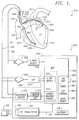
- Figure 1 is a schematic block diagram of a fully implantable defibrillator embodying the present invention for applying defibrillating electrical energy to the atria of a human heart and which is shown in association with a human heart in need of atrial fibrillation monitoring and potential cardioversion of the atria.
- Figure 2 is a flow diagram illustrating the manner in which the atrial defibrillator of Figure 1 may be implemented for providing a patient activated modality, a fully automatic modality, or a combined patient activated and fully automatic modality in accordance with the present invention.
- FIG. 1 it illustrates a fully implantable atrial defibrillator 330 embodying the present invention shown in association with a schematically illustrated human heart 310 in need of atrial fibrillation monitoring and potential cardioversion of the atria.
- the portions of the heart 310 illustrated in Figure 1 are the right ventricle 312, the left ventricle 314, the right atrium 316, the left atrium 318, the superior vena cava 320, the coronary sinus channel 321 which, as used herein, denotes the coronary sinus 322 and the great cardiac vein 323, the coronary sinus ostium or opening 324, the left ventricular free wall 326 and the inferior vena cava 327.
- the atrial defibrillator 330 generally includes an enclosure 332 for hermetically sealing the internal circuit elements of the atrial defibrillator to be described hereinafter, an endocardial first lead 334, and an intravascular second lead 336.
- the enclosure 332 and first and second leads 334 and 336 are arranged to be implanted beneath the skin of a patient so as to render the atrial defibrillator 330 fully implantable.
- the endocardial first lead 334 preferably comprises a endocardial bi-polar lead having electrodes 338 and 340 arranged for establishing electrical contact with the right ventricle 312 of the heart 310.
- the electrodes 338 and 340 permit bi-polar sensing of ventricular activations in the right ventricle.
- the lead 334 is preferably fed through the superior vena cava 320, into the right atrium 316 and then into the right ventricle 312, as illustrated.
- the second lead 336 generally includes a first or tip electrode 344 and a second or proximal electrode 346. As illustrated, the second lead 336 is flexible and arranged to be passed down the superior vena cava 320, into the right atrium 316, into the coronary sinus ostium 324, and advanced into the coronary sinus channel 321 of the heart near the left side thereof so that the first or tip electrode 344 is within the coronary sinus channel 321 either within the coronary sinus 322 adjacent the left ventricle 314 and beneath the left atrium 318 or most preferably within the great cardiac vein 323 adjacent the left ventricle 14 and beneath the left atrium 318.
- the electrodes 344 and 346 are spaced apart such that when the first electrode 344 is positioned as described above, the second electrode 346 is in the right atrium 316.
- the first electrode 344 together with the second electrode 345 provide bi-polar sensing of heart activity in the atria 316 and 318.
- the first electrode 344 and the second electrode 346 further provide for the delivery of defibrillating or cardioverting electrical energy to the atria.
- the atrial defibrillator 330 includes a first sense amplifier 350, an R wave detector 352, and a second sense amplifier 354.
- the output of the first sense amplifier 350 is coupled to the R wave detector 352.
- the R wave detector 352 is of the type well known in the art which provides an output pulse upon the occurrence of an R wave being sensed during a cardiac cycle of the heart.
- the output of the second sense amplifier 354 is coupled to an analog-to-digital convertor 356 which converts the analog signal representative of the atrial activity of the heart being detected to digital samples for further processing in a manner to be described hereinafter.
- the enclosure 332 of the atrial defibrillator 330 further includes a microprocessor 358.
- the microprocessor 358 is preferably implemented in a manner as previously descried or as described in copending U.S. application Serial No. 07/856,514, and further as described hereinafter with respect to the flow diagram of Figure 2.
- the implementation of the microprocessor 358 in accordance with this embodiment of the present invention results in a plurality of functional stages.
- the stages include a sequence initiating stage 360, a timer 362, an activation control stage 364, a mode select stage 366, an atrial fibrillation detector 370, and a charge and delivery control stage 372.
- the microprocessor 358 is arranged to operate in conjunction with a memory (not shown) which may be coupled to the microprocessor 358 by a multiple-bit address bus (not shown) and a bi-directional multiple-bit data bus (not shown). This permits the microprocessor 358 to address desired memory locations within the memory for executing write or read operations.
- the microprocessor stores data and operating parameters (such as a selected modality) in the memory at the addresses defined by multiple-bit addresses conveyed over the address bus and conveys the data to the memory over the multiple-bit data bus.
- the microprocessor 358 obtains data from the memory at the storage locations identified by the multiple-bit addresses provided over the address bus and receives the data from the memory over the bi-directional data bus.
- the microprocessor 358 For entering operating parameters into the microprocessor 358, such as mode selection, the microprocessor 358 receives programmable operating parameters, such as mode commands, from an external controller 400 which is external to the skin of the patient.
- the external controller 400 is arranged to communicate with a receiver/transmitter 402 which is coupled to the microprocessor 358 over a bi-directional bus 404.
- the receiver/transmitter 402 may be of the type well known in the art for conveying various information which it obtains from the microprocessor 358 to the external controller 400 or for receiving programming parameters, such as mode commands, from the external controller 400 which the receiver/transmitter 402 then conveys to the microprocessor 358 for storage in the aforementioned external memory within enclosure 332.
- the receiver/transmitter 402 includes a transmitting coil 406 so that the receiver/transmitter 402 and coil 406 form a communication means.
- Such communication means are well known in the art and may be utilized as noted above for receiving commands from external to the implantable enclosure 332 and for transmitting data to the external controller 400 from the implanted enclosure 332.
- One such communication system is disclosed, for example, in U.S. Patent No. 5,342,408, which is incorporated herein by reference.
- the atrial defibrillator 330 further includes an intervention sequencer 368 which performs an intervention sequence, including atrial fibrillation detection and cardioversion of the atria (if necessary).
- the intervention sequencer includes the previously mentioned atrial fibrillation detector 370 and charge and delivery control 372, and a charger and storage capacitor circuit 374 and a discharge circuit 376.
- Each intervention sequence is begun by the sequence initiating stage 360.
- the sequence initiating stage 360 initiates an intervention sequence at spaced apart times which are preferably determined by the timer 362.
- the sequence initiating stage 360 initiates an intervention sequence when a sequence command generated external to the patient is received by a sequence command receiver, preferably formed by a read switch 363.
- the sequence command in accordance with this preferred embodiment, is a magnetic field generated by a magnet of the type well now in the art which is brought into close proximity with the implanted defibrillator 330.
- the intervention sequencer 368 When the intervention sequencer 368 is not performing an intervention sequence, it is held in a deactivated or inactive state by the activation control stage 364. When an intervention sequence is to be performed, the sequence initiating stage 360 overrides the activation control stage 364 to cause the intervention sequencer to perform an intervention sequence.
- Each intervention sequence preferably begins with the atrial fibrillation detector 370 determining if the atria are in need of cardioversion. This analysis is preferably performed on data obtained from sense amplifier 354 and analog-to-digital convertor 356, which is prestored in the aforementioned memory (not shown) external to the microprocessor 358, but contained within the implantable enclosure 332.
- the atrial fibrillation detector 370 may alternatively be of the type which performs real time analysis of the data provided by the analog-to-digital convertor 356.
- the charger and storage capacitor circuit 374 under control of the charge and delivery stage 372 charges its storage capacitor to a predetermined voltage level for cardioverting the atria of the patient's heart.
- the charge and delivery control stage 372 then causes the discharge circuit 376 to discharge the storage capacitor within circuit 374 for a predetermined time to provide a controlled discharge of cardioverting electrical energy to the atria of the heart.
- the discharge circuit 376 is coupled to the first electrode 344 and the second electrode 346 of the second lead 336 for applying the cardioverting or defibrillating electrical energy to the atria.
- the discharge is preferably initiated in timed relation to an R wave detected by sense amplifier 350 and R wave detector 352. Interval timing prior to energy delivery is also preferably performed as taught in U.S. Patent No. 5,207,219.
- the defibrillator 330 includes a depletable power source 378, such as a lithium battery.
- the battery 378 provides power to the electrical components of the atrial defibrillator 330.
- the atrial defibrillator 330 is first placed into one of a plurality of different modes of operation.
- the selectable modalities include an automatic mode, a patient activated mode, and a combined automatic and patient activated mode.
- the RF transmitter/receiver 402 is activated to determine if the external controller 400 is attempting to communicate with the implanted defibrillator 330.
- the mode select stage 366 when the external controller 400 is transmitting to the transmitter/receiver 402, will determine if a program mode command is being received from the external controller 400. If a program mode control is being received, the mode select stage 366 will decode the mode command and set the defibrillator 330 into the selected mode of operation.
- the mode select stage 366 first determines in step 412 if the received program mode command corresponds to the automatic mode. If it does, it then proceeds to step 414 to set the microprocessor 358 into the automatic mode for obtaining those programs instructions from the external memory which correspond to the automatic mode of operation, to be described subsequently.
- step 412 If in step 412 it is determined that the received program mode command does not correspond to the automatic mode, the mode select stage 366 then proceeds to step 416 to determine if the received program mode command corresponds to the patient activated mode. If it does, the mode select stage 366 then in step 418 sets the microprocessor into the patient activated mode for obtaining those operating instructions from the external memory which correspond to the patient activated mode, to be described subsequently.
- step 416 the mode select stage 366 determines in step 416 that the received program mode command does not correspond to the patient activated mode, it then proceeds to step 420 to set the microprocessor into the combined automatic and patient activated mode. This will cause the microprocessor to obtain those operating instructions from the external memory which correspond to the combined automatic and patient activated mode to be described hereinafter.
- the atrial defibrillator 330 If the atrial defibrillator 330 is set into the automatic mode by the mode select stage 366, in accordance with step 414, the atrial defibrillator 330 will enter the automatic mode.
- the sequence initiating stage 360 causes the intervention sequencer 368 to perform the intervention sequence at spaced apart times and, preferably, predetermined times.
- a timer 362 is first reset and started in step 422.
- the activation control stage 364 maintains the sequence initiator 368 in the deactivated state.
- the sequence initiating stage 360 determines in step 424 that the timer 362 has timed out, the sequence initiating stage 360 then overrides the activation control stage 364 to activate the intervention sequencer 368.
- the atrial fibrillation detector 370 first, in step 426, determines if the atria are in need of cardioversion. If the atria are not in fibrillation, the process returns to step 422 to reset and start timer 362. However, if it is determined in step 426 that the atria are in need of cardioversion, the charge and delivery control stage 372, the charger and storage capacitor circuit 374, and the discharge circuit 376 cardiovert the atria in step 428 in a manner as previously described.
- the atrial fibrillation detector 370 After the cardioverting electrical energy is applied to the atria in step 428, the atrial fibrillation detector 370 once again determines if the atria are in fibrillation in accordance with step 430. If the atria are still in fibrillation, the sequence initiator 368 returns to step 428 to once again apply cardioverting electrical energy to the atria of the heart. However, if in step 430 the atrial fibrillation detector 370 fails to detect atrial fibrillation, the timer 362 is then reset and a new time period is begun.
- the automatic mode will automatically, at predetermined times, determine if the atria are in fibrillation. If the atria are in fibrillation, cardioverting electrical energy is applied to the atria until the atrial fibrillation episode is terminated. Once the atrial fibrillation is terminated, the process returns to reset and start timer 362.
- the sequence initiating stage 460 in step 432 continuously detects for a sequence command generated from external to the patient.
- the sequence command such as a magnetic field generated by an external magnet of the type well known in the art is applied to the implantation site to close and then open read switch 363, the sequence command will have been detected and the sequence initiating stage causes the intervention sequence to be performed.
- the atrial fibrillation detector 370 determines if the atria are in fibrillation and in need of cardioversion. If the atria are not in fibrillation, the process returns for the sequence initiating stage to once again detect a sequence command.
- step 436 cardioverting electrical energy is applied to the heart.
- the atrial fibrillation detector 370 in step 438 determines if the atrial fibrillation episode has been terminated. If it has, the process returns for the sequence initiating stage to detect another sequence command. Of course, when the sequence initiating stage is detecting for a sequence command, the activation control stage 364 maintains the intervention sequencer 368 in the deactivated state. If the atrial fibrillation continues, after cardioversion, the atria are once again cardioverted in step 436. This process continues until the atrial fibrillation episode is terminated.
- intervention sequencer 368 is described above as continuously applying cardioverting electrical energy to the atria of the heart until the heart is successfully cardioverted, it is preferred that such applications of cardioverting electrical energy be limited to a specific number of such applications. To that end, as will be appreciated by those skilled in the art, the number of applications of the cardioverting energy may be counted, and when a predetermined count is reached, the process would then be returned to either reset and start the timer 362 when in the automatic mode, or return to detect another sequence command when in the patient activated mode.
- the timer 362 is first reset and started in step 440. While the timer 362 is timing a predetermined time period, the sequence initiating stage 360 continuously determines in step 442 if a sequence command has been received as previously described and, if not, if the timer 362 has timed out in accordance with step 444. The sequence initiating stage continues to perform steps 442 and 444 until either a sequence command is received or the timer 362 times out. If a sequence command is determined in step 442 to occur prior to the time-out of the timer 362, the sequence initiating stage 360 will first stop timer 362 in step 446 and then cause the intervention sequencer 368 to enter its intervention. sequence by performing steps 434, 436 and 438, as previously described. When the intervention sequence is completed, the timer 362 is reset in step 440 and the process repeats.
- the sequence initiating stage will cause the intervention sequencer 368 to enter its intervention sequence by performing steps 426, 428 and 430, as previously described.
- the timer 62 is once again reset in step 440 and the process repeats.
- the combined automatic and patient activated mode causes the sequence initiating stage to initiate an intervention sequence upon either the receipt of a sequence command (patient activated mode) or upon the time out of the timer 362 (automatic mode).
- the timer 362 is reset and started.
- the present invention provides and atrial defibrillator having selectable modalities, including an automatic mode, a patient activated mode, and a combined automatic and patient activated mode.
- this intervention sequence requires that the atrial defibrillator 330 first detect atrial fibrillation to confirm the patient's diagnoses before allowing cardioverting electrical energy to be applied to the patient's heart.
Abstract
Description
- The present invention generally relates to an implantable atrial defibrillator for applying cardioverting electrical energy to the atria of a patient's heart in need of cardioversion. The present invention is more particularly directed to such a defibrillator which is programmable into a fully automatic mode, a patient activated mode, or a combined automatic and patient activated mode. The atrial defibrillator includes an intervention sequencer which is utilized in all of the selectable modes. The intervention sequencer includes an atrial fibrillation detector for determining if the atria are in need of cardioversion and a cardiovertor for applying cardioverting electrical energy to the atria of the heart.
- Atrial fibrillation is probably the most common cardiac arrhythmia. Although it is not usually a life threatening arrhythmia, it is associated with strokes thought to be caused by blood clots forming in areas of stagnant blood flow as a result of prolonged atrial fibrillation. In addition, patients afflicted with atrial fibrillation generally experience palpitations of the heart and may even experience dizziness.
- Atrial fibrillation occurs suddenly and many times can only be corrected by a discharge of electrical energy to the heart through the skin of the patient by way of an external defibrillator of the type well known in the art.
- This treatment is commonly referred to as synchronized cardioversion and, as its name implies, involves applying electrical defibrillating energy to the heart in synchronism with a detected ventricular electrical activation (R wave) of the heart. The treatment is very painful and, unfortunately, most often only results in temporary relief for patients, lasting but a few weeks.
- Drugs are available for reducing the incidence of atrial fibrillation. However, these drugs have many side effects and many patients are resistant to them which greatly reduces their therapeutic effect.
- Implantable atrial defibrillators have been proposed to provide patients suffering from occurrences of atrial fibrillation with relief. Unfortunately, to the detriment of such patients, none of these atrial defibrillators have become a commercial reality.
- Two such proposed defibrillators, although represented as being implantable, were not fully automatic, requiring human interaction for cardioverting or defibrillating the heart. Both of these proposed defibrillators required the patient to recognize the symptoms of atrial fibrillation with one defibrillator requiring a visit to a physician to activate the defibrillator and the other defibrillator requiring the patient to activate the defibrillator with an external magnet. Neither defibrillator included an atrial fibrillation detector or detected atrial activity of the heart. As a result, these manually operated defibrillators provided no atrial fibrillation detection support for the patient.
- An improved implantable atrial defibrillator which is automatic in operation is fully described in U.S. Patent No. 5,282,837. The atrial defibrillator disclosed in this patent is truly automatic by including an atrial fibrillation detector which, responsive to sensed atrial activity, determines when the atria of the heart are in need of cardioversion. When the atrial fibrillation detector determines that the atria are in fibrillation and thus in need of cardioversion, the atrial fibrillation detector causes a cardiovertor stage to deliver defibrillating or cardioverting electrical energy to the atria in timed relation to a detected ventricular electrical activation (R wave) of the heart. As a result, the atria are automatically and safely cardioverted.
- Because atrial fibrillation, unlike ventricular fibrillation, is generally not immediately life threatening, a fully automatic atrial defibrillation modality may not be necessary for a great number of patients, and especially for those patients who are highly symptomatic. Further, some patients may wish to control when cardioverting therapy is to be delivered. However, even though some patients may be able to accurately diagnose when their heart is experiencing an episode of atrial fibrillation, it would still be desirable to provide a manual or patient activated modality which includes automatic atrial fibrillation detection to confirm the patient's own diagnosis. Hence, if the patient has a perceived atrial fibrillation episode and activates the defibrillator, it would be beneficial to the patient that the defibrillator, prior to cardioversion, confirm, through an atrial fibrillation detector, that atrial fibrillation is actually present. In this way, the patient will not be subjected to unnecessary cardioversion attempts which otherwise may cause discomfort to the patient and early depletion of the defibrillator power source.
- Still other patients may benefit from a combined patient activated and fully automatic modality. For example, patients which are symptomatic some of the time would fall into this category. Such combined modalities must be coordinated and provide atrial fibrillation detection and confirmation to assure that unnecessary cardioversion attempts are not delivered. The present invention provides an atrial defibrillator which satisfies all of these requirements.
- The present invention provides an atrial defibrillator implantable beneath the skin of a patient, including an intervention sequencer for performing an intervention sequence. The intervention sequencer includes an atrial fibrillation detector for determining if atrial fibrillation is present in a patient's heart and a cardiovertor for applying cardioverting electrical energy to the atria of the patient's heart if the atrial fibrillation detector determines that atrial fibrillation is present. The atrial defibrillator further includes a sequence initiating stage including a receiver for receiving a sequence command generated form external to the patient for causing the intervention sequencer to perform the intervention sequence. The atrial defibrillator further includes a mode selector responsive to mode commands generated from external to the patient. In accordance with one aspect of the present invention, the mode selector is responsive to a patient activated mode command for causing the sequence initiating stage to activate the intervention sequencer only in response to the sequence command generated from external to the patient and an automatic mode command for causing the sequence initiating stage to activate the intervention sequencer at predetermined times. In accordance with a further aspect of the present invention, the mode selector is responsive to a combined automatic and patient activated mode command for causing the sequence initiating stage to activate the intervention sequencer both in response to the sequence command generated from external to the patient and at predetermined times.
- Figure 1 is a schematic block diagram of a fully implantable defibrillator embodying the present invention for applying defibrillating electrical energy to the atria of a human heart and which is shown in association with a human heart in need of atrial fibrillation monitoring and potential cardioversion of the atria.
- Figure 2 is a flow diagram illustrating the manner in which the atrial defibrillator of Figure 1 may be implemented for providing a patient activated modality, a fully automatic modality, or a combined patient activated and fully automatic modality in accordance with the present invention.
- Referring now to Figure 1, it illustrates a fully implantable
atrial defibrillator 330 embodying the present invention shown in association with a schematically illustrated human heart 310 in need of atrial fibrillation monitoring and potential cardioversion of the atria. The portions of the heart 310 illustrated in Figure 1 are theright ventricle 312, theleft ventricle 314, theright atrium 316, theleft atrium 318, thesuperior vena cava 320, thecoronary sinus channel 321 which, as used herein, denotes thecoronary sinus 322 and the greatcardiac vein 323, the coronary sinus ostium or opening 324, the left ventricularfree wall 326 and theinferior vena cava 327. - The
atrial defibrillator 330 generally includes anenclosure 332 for hermetically sealing the internal circuit elements of the atrial defibrillator to be described hereinafter, an endocardialfirst lead 334, and an intravascularsecond lead 336. Theenclosure 332 and first and second leads 334 and 336 are arranged to be implanted beneath the skin of a patient so as to render theatrial defibrillator 330 fully implantable. - The endocardial
first lead 334 preferably comprises a endocardial bi-polarlead having electrodes right ventricle 312 of the heart 310. Theelectrodes lead 334 is preferably fed through thesuperior vena cava 320, into theright atrium 316 and then into theright ventricle 312, as illustrated. - The
second lead 336 generally includes a first ortip electrode 344 and a second orproximal electrode 346. As illustrated, thesecond lead 336 is flexible and arranged to be passed down thesuperior vena cava 320, into theright atrium 316, into thecoronary sinus ostium 324, and advanced into thecoronary sinus channel 321 of the heart near the left side thereof so that the first ortip electrode 344 is within thecoronary sinus channel 321 either within thecoronary sinus 322 adjacent theleft ventricle 314 and beneath theleft atrium 318 or most preferably within the greatcardiac vein 323 adjacent the left ventricle 14 and beneath theleft atrium 318. Theelectrodes first electrode 344 is positioned as described above, thesecond electrode 346 is in theright atrium 316. - The
first electrode 344 together with the second electrode 345 provide bi-polar sensing of heart activity in theatria first electrode 344 and thesecond electrode 346 further provide for the delivery of defibrillating or cardioverting electrical energy to the atria. - Within the
enclosure 332, theatrial defibrillator 330 includes afirst sense amplifier 350, anR wave detector 352, and asecond sense amplifier 354. Thefirst sense amplifier 350 and theR wave detector 352, together withelectrodes lead 334, sense ventricular activations of theright ventricle 312. Thesecond sense amplifier 354, together with thefirst electrode 344 andsecond electrode 346 of thesecond lead 336, detect atrial activity of the heart. - The output of the
first sense amplifier 350 is coupled to theR wave detector 352. TheR wave detector 352 is of the type well known in the art which provides an output pulse upon the occurrence of an R wave being sensed during a cardiac cycle of the heart. The output of thesecond sense amplifier 354 is coupled to an analog-to-digital convertor 356 which converts the analog signal representative of the atrial activity of the heart being detected to digital samples for further processing in a manner to be described hereinafter. - The
enclosure 332 of theatrial defibrillator 330 further includes amicroprocessor 358. Themicroprocessor 358 is preferably implemented in a manner as previously descried or as described in copending U.S. application Serial No. 07/856,514, and further as described hereinafter with respect to the flow diagram of Figure 2. The implementation of themicroprocessor 358 in accordance with this embodiment of the present invention results in a plurality of functional stages. The stages include asequence initiating stage 360, atimer 362, anactivation control stage 364, a modeselect stage 366, anatrial fibrillation detector 370, and a charge and delivery control stage 372. - The
microprocessor 358 is arranged to operate in conjunction with a memory (not shown) which may be coupled to themicroprocessor 358 by a multiple-bit address bus (not shown) and a bi-directional multiple-bit data bus (not shown). This permits themicroprocessor 358 to address desired memory locations within the memory for executing write or read operations. During a write operation, the microprocessor stores data and operating parameters (such as a selected modality) in the memory at the addresses defined by multiple-bit addresses conveyed over the address bus and conveys the data to the memory over the multiple-bit data bus. During a read operation, themicroprocessor 358 obtains data from the memory at the storage locations identified by the multiple-bit addresses provided over the address bus and receives the data from the memory over the bi-directional data bus. - For entering operating parameters into the
microprocessor 358, such as mode selection, themicroprocessor 358 receives programmable operating parameters, such as mode commands, from an external controller 400 which is external to the skin of the patient. The external controller 400 is arranged to communicate with a receiver/transmitter 402 which is coupled to themicroprocessor 358 over a bi-directional bus 404. The receiver/transmitter 402 may be of the type well known in the art for conveying various information which it obtains from themicroprocessor 358 to the external controller 400 or for receiving programming parameters, such as mode commands, from the external controller 400 which the receiver/transmitter 402 then conveys to themicroprocessor 358 for storage in the aforementioned external memory withinenclosure 332. - The receiver/
transmitter 402 includes a transmittingcoil 406 so that the receiver/transmitter 402 andcoil 406 form a communication means. Such communication means are well known in the art and may be utilized as noted above for receiving commands from external to theimplantable enclosure 332 and for transmitting data to the external controller 400 from the implantedenclosure 332. One such communication system is disclosed, for example, in U.S. Patent No. 5,342,408, which is incorporated herein by reference. - The
atrial defibrillator 330 further includes anintervention sequencer 368 which performs an intervention sequence, including atrial fibrillation detection and cardioversion of the atria (if necessary). To that end, the intervention sequencer includes the previously mentionedatrial fibrillation detector 370 and charge and delivery control 372, and a charger andstorage capacitor circuit 374 and adischarge circuit 376. - Each intervention sequence is begun by the
sequence initiating stage 360. As will be seen hereinafter, when thedefibrillator 330 is programmed in the automatic mode, thesequence initiating stage 360 initiates an intervention sequence at spaced apart times which are preferably determined by thetimer 362. When the defibrillator is programmed in the patient activated mode, thesequence initiating stage 360 initiates an intervention sequence when a sequence command generated external to the patient is received by a sequence command receiver, preferably formed by aread switch 363. The sequence command, in accordance with this preferred embodiment, is a magnetic field generated by a magnet of the type well now in the art which is brought into close proximity with the implanteddefibrillator 330. When theintervention sequencer 368 is not performing an intervention sequence, it is held in a deactivated or inactive state by theactivation control stage 364. When an intervention sequence is to be performed, thesequence initiating stage 360 overrides theactivation control stage 364 to cause the intervention sequencer to perform an intervention sequence. - Each intervention sequence preferably begins with the
atrial fibrillation detector 370 determining if the atria are in need of cardioversion. This analysis is preferably performed on data obtained fromsense amplifier 354 and analog-to-digital convertor 356, which is prestored in the aforementioned memory (not shown) external to themicroprocessor 358, but contained within theimplantable enclosure 332. Theatrial fibrillation detector 370 may alternatively be of the type which performs real time analysis of the data provided by the analog-to-digital convertor 356. - If the atria are in fibrillation, and hence in need of cardioversion, the charger and
storage capacitor circuit 374 under control of the charge and delivery stage 372 charges its storage capacitor to a predetermined voltage level for cardioverting the atria of the patient's heart. When the capacitor ofcircuit 374 is charged, the charge and delivery control stage 372 then causes thedischarge circuit 376 to discharge the storage capacitor withincircuit 374 for a predetermined time to provide a controlled discharge of cardioverting electrical energy to the atria of the heart. To that end, thedischarge circuit 376 is coupled to thefirst electrode 344 and thesecond electrode 346 of thesecond lead 336 for applying the cardioverting or defibrillating electrical energy to the atria. The discharge is preferably initiated in timed relation to an R wave detected bysense amplifier 350 andR wave detector 352. Interval timing prior to energy delivery is also preferably performed as taught in U.S. Patent No. 5,207,219. - Lastly, the
defibrillator 330 includes adepletable power source 378, such as a lithium battery. Thebattery 378, of course, provides power to the electrical components of theatrial defibrillator 330. - The overall operation of the
atrial defibrillator 330 will now be described in connection with the flow diagram of Figure 2. Referring now to Figure 2, theatrial defibrillator 330 is first placed into one of a plurality of different modes of operation. In accordance with this preferred embodiment, the selectable modalities include an automatic mode, a patient activated mode, and a combined automatic and patient activated mode. To that end, at relatively short, predetermined time intervals, the RF transmitter/receiver 402 is activated to determine if the external controller 400 is attempting to communicate with the implanteddefibrillator 330. As a result, in accordance withstep 410, the modeselect stage 366, when the external controller 400 is transmitting to the transmitter/receiver 402, will determine if a program mode command is being received from the external controller 400. If a program mode control is being received, the modeselect stage 366 will decode the mode command and set thedefibrillator 330 into the selected mode of operation. - The mode
select stage 366 first determines instep 412 if the received program mode command corresponds to the automatic mode. If it does, it then proceeds to step 414 to set themicroprocessor 358 into the automatic mode for obtaining those programs instructions from the external memory which correspond to the automatic mode of operation, to be described subsequently. - If in
step 412 it is determined that the received program mode command does not correspond to the automatic mode, the modeselect stage 366 then proceeds to step 416 to determine if the received program mode command corresponds to the patient activated mode. If it does, the modeselect stage 366 then instep 418 sets the microprocessor into the patient activated mode for obtaining those operating instructions from the external memory which correspond to the patient activated mode, to be described subsequently. - If in
step 416, the modeselect stage 366 determines instep 416 that the received program mode command does not correspond to the patient activated mode, it then proceeds to step 420 to set the microprocessor into the combined automatic and patient activated mode. This will cause the microprocessor to obtain those operating instructions from the external memory which correspond to the combined automatic and patient activated mode to be described hereinafter. - If the
atrial defibrillator 330 is set into the automatic mode by the modeselect stage 366, in accordance withstep 414, theatrial defibrillator 330 will enter the automatic mode. In the automatic mode, thesequence initiating stage 360 causes theintervention sequencer 368 to perform the intervention sequence at spaced apart times and, preferably, predetermined times. To that end, atimer 362 is first reset and started instep 422. At this time, theactivation control stage 364 maintains thesequence initiator 368 in the deactivated state. - When the
sequence initiating stage 360 determines instep 424 that thetimer 362 has timed out, thesequence initiating stage 360 then overrides theactivation control stage 364 to activate theintervention sequencer 368. Theatrial fibrillation detector 370 first, instep 426, determines if the atria are in need of cardioversion. If the atria are not in fibrillation, the process returns to step 422 to reset and starttimer 362. However, if it is determined instep 426 that the atria are in need of cardioversion, the charge and delivery control stage 372, the charger andstorage capacitor circuit 374, and thedischarge circuit 376 cardiovert the atria instep 428 in a manner as previously described. After the cardioverting electrical energy is applied to the atria instep 428, theatrial fibrillation detector 370 once again determines if the atria are in fibrillation in accordance withstep 430. If the atria are still in fibrillation, thesequence initiator 368 returns to step 428 to once again apply cardioverting electrical energy to the atria of the heart. However, if instep 430 theatrial fibrillation detector 370 fails to detect atrial fibrillation, thetimer 362 is then reset and a new time period is begun. - From the above, it can be seen that the automatic mode will automatically, at predetermined times, determine if the atria are in fibrillation. If the atria are in fibrillation, cardioverting electrical energy is applied to the atria until the atrial fibrillation episode is terminated. Once the atrial fibrillation is terminated, the process returns to reset and start
timer 362. - If the patient activated
mode 416 is selected, the sequence initiating stage 460 instep 432 continuously detects for a sequence command generated from external to the patient. When the sequence command, such as a magnetic field generated by an external magnet of the type well known in the art is applied to the implantation site to close and then open readswitch 363, the sequence command will have been detected and the sequence initiating stage causes the intervention sequence to be performed. To that end, instep 434, theatrial fibrillation detector 370 determines if the atria are in fibrillation and in need of cardioversion. If the atria are not in fibrillation, the process returns for the sequence initiating stage to once again detect a sequence command. However, if atria are in fibrillation, then instep 436, cardioverting electrical energy is applied to the heart. After the cardioverting electrical energy is applied to the heart, theatrial fibrillation detector 370 instep 438 determines if the atrial fibrillation episode has been terminated. If it has, the process returns for the sequence initiating stage to detect another sequence command. Of course, when the sequence initiating stage is detecting for a sequence command, theactivation control stage 364 maintains theintervention sequencer 368 in the deactivated state. If the atrial fibrillation continues, after cardioversion, the atria are once again cardioverted instep 436. This process continues until the atrial fibrillation episode is terminated. - Although the
intervention sequencer 368 is described above as continuously applying cardioverting electrical energy to the atria of the heart until the heart is successfully cardioverted, it is preferred that such applications of cardioverting electrical energy be limited to a specific number of such applications. To that end, as will be appreciated by those skilled in the art, the number of applications of the cardioverting energy may be counted, and when a predetermined count is reached, the process would then be returned to either reset and start thetimer 362 when in the automatic mode, or return to detect another sequence command when in the patient activated mode. - If the atrial defibrillator is programmed into the combined automatic and patient activated mode, the
timer 362 is first reset and started instep 440. While thetimer 362 is timing a predetermined time period, thesequence initiating stage 360 continuously determines instep 442 if a sequence command has been received as previously described and, if not, if thetimer 362 has timed out in accordance withstep 444. The sequence initiating stage continues to performsteps timer 362 times out. If a sequence command is determined instep 442 to occur prior to the time-out of thetimer 362, thesequence initiating stage 360 will first stoptimer 362 instep 446 and then cause theintervention sequencer 368 to enter its intervention. sequence by performingsteps timer 362 is reset instep 440 and the process repeats. - If the
timer 362 times out prior to the receipt of a sequence command, the sequence initiating stage will cause theintervention sequencer 368 to enter its intervention sequence by performingsteps step 440 and the process repeats. - Hence, from the above description, it will be noted that the combined automatic and patient activated mode causes the sequence initiating stage to initiate an intervention sequence upon either the receipt of a sequence command (patient activated mode) or upon the time out of the timer 362 (automatic mode). After the intervention sequence is completed, and regardless of whether the intervention sequence was initiated due to the receipt of a sequence command or the time out of the
timer 362, thetimer 362 is reset and started. - As can thus be seen, the present invention provides and atrial defibrillator having selectable modalities, including an automatic mode, a patient activated mode, and a combined automatic and patient activated mode. In the patient activated mode, while the patient is enabled to initiate an intervention sequence, this intervention sequence requires that the
atrial defibrillator 330 first detect atrial fibrillation to confirm the patient's diagnoses before allowing cardioverting electrical energy to be applied to the patient's heart. - While particular embodiments of the present invention have been shown and described, modifications may be made. Hence, it is therefore intended in the appended claims to cover all such changes and modifications which fall within the true spirit and scope of the invention.
Claims (3)
- An atrial defibrillator (330) implantable beneath the skin of a patient including an intervention sequencer (368) for performing, when activated, an intervention sequence, the intervention sequencer including an atrial fibrillation detector (370) for determining if atrial fibrillation is present in a patient's heart and a cardiovertor (376) for applying cardioverting electrical energy to the atria of the patient's heart if the atrial fibrillation detector determines that atrial fibrillation is present, the atrial defibrillator characterized by a sequence initiating stage (360) for causing the intervention sequencer to perform the intervention sequence, and including a receiver (363) for receiving a sequence command generated from external to the patient, and a mode selector (366) responsive to responsive to mode commands generated from external to the patient, including a patient activated mode command for causing the sequence initiating stage to activate the intervention sequencer only in response to the sequence command generated from external to the patient and an automatic mode command for causing the sequence initiating stage to activate the intervention sequencer at predetermined times.
- The atrial defibrillator of claim 1 further characterized by the receiver being a read switch.
- The atrial defibrillator of claim 1 further characterized by the mode selector being responsive to a combined automatic and patient activated mode command for causing the sequence initiating stage to activate the intervention sequencer both in response to the sequence command generated from external to the patient and at predetermined times.
Applications Claiming Priority (2)
| Application Number | Priority Date | Filing Date | Title |
|---|---|---|---|
| US306665 | 1994-09-15 | ||
| US08/306,665 US5490862A (en) | 1991-04-12 | 1994-09-15 | Atrial defibrillator having patient activated modality |
Publications (2)
| Publication Number | Publication Date |
|---|---|
| EP0701838A2 true EP0701838A2 (en) | 1996-03-20 |
| EP0701838A3 EP0701838A3 (en) | 1999-01-07 |
Family
ID=23186297
Family Applications (1)
| Application Number | Title | Priority Date | Filing Date |
|---|---|---|---|
| EP95250216A Withdrawn EP0701838A3 (en) | 1994-09-15 | 1995-09-06 | Atrial defibrillator having patient activated modality |
Country Status (4)
| Country | Link |
|---|---|
| US (2) | US5490862A (en) |
| EP (1) | EP0701838A3 (en) |
| AU (1) | AU690720B2 (en) |
| CA (1) | CA2156703C (en) |
Cited By (1)
| Publication number | Priority date | Publication date | Assignee | Title |
|---|---|---|---|---|
| EP0996484A1 (en) * | 1998-04-15 | 2000-05-03 | Cardiac Pacemakers, Inc. | Atrial defibrillation system having patient selectable atrial fibrillation detection |
Families Citing this family (54)
| Publication number | Priority date | Publication date | Assignee | Title |
|---|---|---|---|---|
| US5662689A (en) * | 1995-09-08 | 1997-09-02 | Medtronic, Inc. | Method and apparatus for alleviating cardioversion shock pain |
| US5674249A (en) * | 1996-05-02 | 1997-10-07 | Incontrol, Inc. | Atrial defibrillation system having a portable communication device |
| US6496715B1 (en) | 1996-07-11 | 2002-12-17 | Medtronic, Inc. | System and method for non-invasive determination of optimal orientation of an implantable sensing device |
| JP2000514682A (en) | 1996-07-11 | 2000-11-07 | メドトロニック・インコーポレーテッド | Minimal invasive implantable device for monitoring physiological events |
| SE9603000D0 (en) * | 1996-08-16 | 1996-08-16 | Pacesetter Ab | Implantable apparatus |
| US5755737A (en) * | 1996-12-13 | 1998-05-26 | Medtronic, Inc. | Method and apparatus for diagnosis and treatment of arrhythmias |
| US5836975A (en) * | 1996-12-19 | 1998-11-17 | Medtronic, Inc. | Method and apparatus for diagnosis and treatment of arrhythmias |
| US6024740A (en) | 1997-07-08 | 2000-02-15 | The Regents Of The University Of California | Circumferential ablation device assembly |
| US5987356A (en) * | 1997-06-05 | 1999-11-16 | Medtronic, Inc. | Method and apparatus for diagnosis and treatment of arrhythmias |
| US5800497A (en) * | 1997-07-17 | 1998-09-01 | Medtronic, Inc. | Medical electrical lead with temporarily stiff portion |
| US5868680A (en) * | 1997-09-23 | 1999-02-09 | The Regents Of The University Of California | Quantitative characterization of fibrillatory spatiotemporal organization |
| US6068651A (en) * | 1998-03-26 | 2000-05-30 | Pacesetter, Inc. | Atrial defibrillation lock out feature |
| US6006132A (en) | 1998-04-15 | 1999-12-21 | Tacker, Jr.; Willis A. | Atrial defibrillation system including a portable audible speech communication device |
| USRE38515E1 (en) * | 1998-04-15 | 2004-05-18 | Cardiac Pacemakers, Inc. | Atrial defibrillation system having patient selectable atrial fibrillation detection |
| US6091988A (en) * | 1998-04-30 | 2000-07-18 | Medtronic, Inc. | Apparatus for treating atrial tachyarrhythmias with synchronized shocks |
| US6081745A (en) * | 1998-08-17 | 2000-06-27 | Medtronic, Inc. | Method and apparatus for treatment of arrhythmias |
| US6195584B1 (en) | 1999-04-30 | 2001-02-27 | Medtronic, Inc. | Method and apparatus for determining atrial lead dislocation |
| US6236882B1 (en) | 1999-07-14 | 2001-05-22 | Medtronic, Inc. | Noise rejection for monitoring ECG's |
| US6347245B1 (en) * | 1999-07-14 | 2002-02-12 | Medtronic, Inc. | Medical device ECG marker for use in compressed data system |
| US6272380B1 (en) | 1999-08-19 | 2001-08-07 | Medtronic, Inc. | Apparatus for treating atrial tachy arrhythmias with synchronized shocks |
| WO2001017610A1 (en) * | 1999-09-07 | 2001-03-15 | Uab Research Foundation | Method and apparatus for treating cardiac arrhythmia |
| US7085601B1 (en) * | 1999-11-17 | 2006-08-01 | Koninklijke Philips Electronics N.V. | External atrial defibrillator and method for personal termination of atrial fibrillation |
| US6519490B1 (en) * | 1999-12-20 | 2003-02-11 | Joseph Wiesel | Method of and apparatus for detecting arrhythmia and fibrillation |
| US20020026223A1 (en) * | 1999-12-24 | 2002-02-28 | Riff Kenneth M. | Method and a system for using implanted medical device data for accessing therapies |
| JP4638570B2 (en) * | 2000-01-25 | 2011-02-23 | ヤーマン株式会社 | Momentum measuring device with body fat measurement function |
| US6400990B1 (en) | 2000-02-18 | 2002-06-04 | Pacesetter, Inc. | Patient activated telemetry control unit using bidirectional asymmetric dual-mode telemetry link to communicate with an implanted device |
| US6699200B2 (en) | 2000-03-01 | 2004-03-02 | Medtronic, Inc. | Implantable medical device with multi-vector sensing electrodes |
| CA2416642A1 (en) * | 2000-07-27 | 2002-02-07 | Medtronic, Inc. | Algorithm for synchronization of atrial cardioversion shock |
| US6980857B2 (en) * | 2001-04-20 | 2005-12-27 | Cardiac Pacemakers, Inc. | Patient controlled atrial shock therapy |
| US6618617B2 (en) | 2001-04-20 | 2003-09-09 | Cardiac Pacemakers, Inc. | Delay to therapy following patient controlled atrial shock therapy request |
| US6932804B2 (en) | 2003-01-21 | 2005-08-23 | The Regents Of The University Of California | System and method for forming a non-ablative cardiac conduction block |
| US7317950B2 (en) | 2002-11-16 | 2008-01-08 | The Regents Of The University Of California | Cardiac stimulation system with delivery of conductive agent |
| US20040210256A1 (en) * | 2003-04-17 | 2004-10-21 | Medtronic, Inc. | Methods and apparatus for decreasing incidences of early recurrence of atrial fibrillation |
| US20040230246A1 (en) * | 2003-05-15 | 2004-11-18 | Stein Richard E. | Patient controlled therapy management and diagnostic device with human factors interface |
| US20040230247A1 (en) * | 2003-05-15 | 2004-11-18 | Stein Richard E. | Patient controlled therapy management and diagnostic device with human factors interface |
| US7515963B2 (en) * | 2003-12-16 | 2009-04-07 | Cardiac Pacemakers, Inc. | Method of patient initiated electro-cardiogram storage, status query and therapy activation |
| US8160697B2 (en) | 2005-01-25 | 2012-04-17 | Cameron Health, Inc. | Method for adapting charge initiation for an implantable cardioverter-defibrillator |
| US7294195B2 (en) * | 2005-08-08 | 2007-11-13 | Wacker Chemical Corporation | Water repellant gypsum compositions |
| US7734335B2 (en) * | 2005-09-29 | 2010-06-08 | Hewlett-Packard Development Company, L.P. | Method and apparatus for improving the accuracy of atrial fibrillation detection in lossy data systems |
| DE102005047320A1 (en) * | 2005-09-30 | 2007-04-05 | Biotronik Crm Patent Ag | Detector for atrial flicker and flutter |
| US20070265667A1 (en) | 2006-05-15 | 2007-11-15 | Dirk Muessig | Semi-automatic atrial defibrillation system, implantable atrial defibrillator and portable communication device |
| US7623909B2 (en) | 2006-05-26 | 2009-11-24 | Cameron Health, Inc. | Implantable medical devices and programmers adapted for sensing vector selection |
| US8200341B2 (en) | 2007-02-07 | 2012-06-12 | Cameron Health, Inc. | Sensing vector selection in a cardiac stimulus device with postural assessment |
| US8788023B2 (en) | 2006-05-26 | 2014-07-22 | Cameron Health, Inc. | Systems and methods for sensing vector selection in an implantable medical device |
| DE102006061988A1 (en) | 2006-12-21 | 2008-07-03 | Biotronik Crm Patent Ag | Arterial fibrillation or flutter detector for use in e.g. implantable heart pacemaker, has evaluation unit dividing arterial signal into sequential sections, where peak-to-peak amplitude of signals is smaller than comparison value |
| US7840676B2 (en) * | 2007-01-30 | 2010-11-23 | Hewlett-Packard Development Company, L.P. | Method and system for shedding load in physiological signals processing |
| US7761140B2 (en) * | 2007-01-30 | 2010-07-20 | Hewlett-Packard Development Company, L.P. | State-based load shedding for physiological signals |
| CA2717442C (en) | 2008-03-07 | 2017-11-07 | Cameron Health, Inc. | Accurate cardiac event detection in an implantable cardiac stimulus device |
| US8160686B2 (en) | 2008-03-07 | 2012-04-17 | Cameron Health, Inc. | Methods and devices for accurately classifying cardiac activity |
| JP5656293B2 (en) * | 2008-05-07 | 2015-01-21 | キャメロン ヘルス、 インコーポレイテッド | Implantable heart stimulation (ICS) system |
| CA2766866A1 (en) | 2009-06-29 | 2011-01-20 | Cameron Health, Inc. | Adaptive confirmation of treatable arrhythmia in implantable cardiac stimulus devices |
| US9149645B2 (en) | 2013-03-11 | 2015-10-06 | Cameron Health, Inc. | Methods and devices implementing dual criteria for arrhythmia detection |
| US9579065B2 (en) | 2013-03-12 | 2017-02-28 | Cameron Health Inc. | Cardiac signal vector selection with monophasic and biphasic shape consideration |
| US9554714B2 (en) | 2014-08-14 | 2017-01-31 | Cameron Health Inc. | Use of detection profiles in an implantable medical device |
Citations (2)
| Publication number | Priority date | Publication date | Assignee | Title |
|---|---|---|---|---|
| US5207219A (en) | 1992-10-23 | 1993-05-04 | Incontrol, Inc. | Atrial defibrillator and method for providing interval timing prior to cardioversion |
| US5342408A (en) | 1993-01-07 | 1994-08-30 | Incontrol, Inc. | Telemetry system for an implantable cardiac device |
Family Cites Families (8)
| Publication number | Priority date | Publication date | Assignee | Title |
|---|---|---|---|---|
| US3952750A (en) * | 1974-04-25 | 1976-04-27 | Mieczyslaw Mirowski | Command atrial cardioverting device |
| US4202340A (en) * | 1975-09-30 | 1980-05-13 | Mieczyslaw Mirowski | Method and apparatus for monitoring heart activity, detecting abnormalities, and cardioverting a malfunctioning heart |
| US4365633A (en) * | 1980-02-22 | 1982-12-28 | Telectronics Pty. Ltd. | Patient-operated pacemaker programmer |
| US4860751A (en) * | 1985-02-04 | 1989-08-29 | Cordis Corporation | Activity sensor for pacemaker control |
| US4785812A (en) * | 1986-11-26 | 1988-11-22 | First Medical Devices Corporation | Protection system for preventing defibrillation with incorrect or improperly connected electrodes |
| US5269301A (en) * | 1987-10-06 | 1993-12-14 | Leonard Bloom | Multimode system for monitoring and treating a malfunctioning heart |
| US5190034A (en) * | 1991-01-10 | 1993-03-02 | Siemens Pacesetter, Inc. | Implantable arrhythmia system with protection against release of unneeded pulses |
| US5439481A (en) * | 1992-02-26 | 1995-08-08 | Angeion Corporation | Semi-automatic atrial and ventricular cardioverter defibrillator |
-
1994
- 1994-09-15 US US08/306,665 patent/US5490862A/en not_active Expired - Lifetime
-
1995
- 1995-03-27 US US08/410,829 patent/US5464431A/en not_active Expired - Lifetime
- 1995-08-22 CA CA002156703A patent/CA2156703C/en not_active Expired - Fee Related
- 1995-08-23 AU AU30217/95A patent/AU690720B2/en not_active Ceased
- 1995-09-06 EP EP95250216A patent/EP0701838A3/en not_active Withdrawn
Patent Citations (2)
| Publication number | Priority date | Publication date | Assignee | Title |
|---|---|---|---|---|
| US5207219A (en) | 1992-10-23 | 1993-05-04 | Incontrol, Inc. | Atrial defibrillator and method for providing interval timing prior to cardioversion |
| US5342408A (en) | 1993-01-07 | 1994-08-30 | Incontrol, Inc. | Telemetry system for an implantable cardiac device |
Cited By (2)
| Publication number | Priority date | Publication date | Assignee | Title |
|---|---|---|---|---|
| EP0996484A1 (en) * | 1998-04-15 | 2000-05-03 | Cardiac Pacemakers, Inc. | Atrial defibrillation system having patient selectable atrial fibrillation detection |
| EP0996484A4 (en) * | 1998-04-15 | 2008-10-15 | Cardiac Pacemakers Inc | Atrial defibrillation system having patient selectable atrial fibrillation detection |
Also Published As
| Publication number | Publication date |
|---|---|
| US5490862A (en) | 1996-02-13 |
| CA2156703C (en) | 2000-10-03 |
| CA2156703A1 (en) | 1996-03-16 |
| AU690720B2 (en) | 1998-04-30 |
| US5464431A (en) | 1995-11-07 |
| EP0701838A3 (en) | 1999-01-07 |
| AU3021795A (en) | 1996-03-28 |
Similar Documents
| Publication | Publication Date | Title |
|---|---|---|
| EP0701838A2 (en) | Atrial defibrillator having patient activated modality | |
| US5395373A (en) | Atrial defibrillator and method for setting energy threshold values | |
| US5332400A (en) | Atrial defibrillator and method for providing pre-cardioversion warning | |
| US5674249A (en) | Atrial defibrillation system having a portable communication device | |
| US5304139A (en) | Improved lead configuration for an atrial defibrillator | |
| AU755924B2 (en) | Method and system for detecting dislodgement of an implanted right atrial endocardial lead | |
| AU757287B2 (en) | Cardioverter and method for cardioverting an atrial tachyarrhythmia while maintaining atrial pacing | |
| US5265600A (en) | Atrial defibrillator and method for providing post-cardioversion pacing | |
| US5464432A (en) | Implantable atrial defibrillator having an intermittently activated fibrillation detector | |
| EP0627240A2 (en) | Atrial defibrillator and method for providing T wave detection and interval timing prior to cardioversion | |
| US6249699B1 (en) | Cardioverter and method for cardioverting an atrial tachyarrhythmia in the presence of atrial pacing | |
| AU757474B2 (en) | Method and system for detecting dislodgment of an implanted right atrial endocardial lead using a sensing period derived from a ventricular lead | |
| US5991662A (en) | Method and system for detecting dislodgment of an implanted right atrial endocardial lead using sensing periods established with one other lead | |
| US5554175A (en) | Therapy termination in an atrial defibrillator and method | |
| US5813999A (en) | Implantable atrial defibrillator providing reduced cardioversion discomfort | |
| CA2311266C (en) | Atrial defibrillator having patient activated modality |
Legal Events
| Date | Code | Title | Description |
|---|---|---|---|
| PUAI | Public reference made under article 153(3) epc to a published international application that has entered the european phase |
Free format text: ORIGINAL CODE: 0009012 |
|
| AK | Designated contracting states |
Kind code of ref document: A2 Designated state(s): BE CH DE FR IT LI NL SE |
|
| RIN1 | Information on inventor provided before grant (corrected) |
Inventor name: ALFERNESS, CLIFTON A. Inventor name: ADAMS, JOHN M. |
|
| PUAL | Search report despatched |
Free format text: ORIGINAL CODE: 0009013 |
|
| RHK1 | Main classification (correction) |
Ipc: A61N 1/39 |
|
| AK | Designated contracting states |
Kind code of ref document: A3 Designated state(s): BE CH DE FR IT LI NL SE |
|
| RAP1 | Party data changed (applicant data changed or rights of an application transferred) |
Owner name: CARDIAC PACEMAKERS, INC. |
|
| 17P | Request for examination filed |
Effective date: 19990623 |
|
| 17Q | First examination report despatched |
Effective date: 20010606 |
|
| GRAH | Despatch of communication of intention to grant a patent |
Free format text: ORIGINAL CODE: EPIDOS IGRA |
|
| STAA | Information on the status of an ep patent application or granted ep patent |
Free format text: STATUS: THE APPLICATION IS DEEMED TO BE WITHDRAWN |
|
| 18D | Application deemed to be withdrawn |
Effective date: 20030701 |