EP0701805A1 - Apertured plastic film - Google Patents
Apertured plastic film Download PDFInfo
- Publication number
- EP0701805A1 EP0701805A1 EP95114562A EP95114562A EP0701805A1 EP 0701805 A1 EP0701805 A1 EP 0701805A1 EP 95114562 A EP95114562 A EP 95114562A EP 95114562 A EP95114562 A EP 95114562A EP 0701805 A1 EP0701805 A1 EP 0701805A1
- Authority
- EP
- European Patent Office
- Prior art keywords
- film
- holes
- apertured film
- apertured
- micro
- Prior art date
- Legal status (The legal status is an assumption and is not a legal conclusion. Google has not performed a legal analysis and makes no representation as to the accuracy of the status listed.)
- Granted
Links
Images


Classifications
-
- A—HUMAN NECESSITIES
- A61—MEDICAL OR VETERINARY SCIENCE; HYGIENE
- A61F—FILTERS IMPLANTABLE INTO BLOOD VESSELS; PROSTHESES; DEVICES PROVIDING PATENCY TO, OR PREVENTING COLLAPSING OF, TUBULAR STRUCTURES OF THE BODY, e.g. STENTS; ORTHOPAEDIC, NURSING OR CONTRACEPTIVE DEVICES; FOMENTATION; TREATMENT OR PROTECTION OF EYES OR EARS; BANDAGES, DRESSINGS OR ABSORBENT PADS; FIRST-AID KITS
- A61F13/00—Bandages or dressings; Absorbent pads
- A61F13/15—Absorbent pads, e.g. sanitary towels, swabs or tampons for external or internal application to the body; Supporting or fastening means therefor; Tampon applicators
- A61F13/51—Absorbent pads, e.g. sanitary towels, swabs or tampons for external or internal application to the body; Supporting or fastening means therefor; Tampon applicators characterised by the outer layers
- A61F13/511—Topsheet, i.e. the permeable cover or layer facing the skin
- A61F13/512—Topsheet, i.e. the permeable cover or layer facing the skin characterised by its apertures, e.g. perforations
-
- A—HUMAN NECESSITIES
- A61—MEDICAL OR VETERINARY SCIENCE; HYGIENE
- A61F—FILTERS IMPLANTABLE INTO BLOOD VESSELS; PROSTHESES; DEVICES PROVIDING PATENCY TO, OR PREVENTING COLLAPSING OF, TUBULAR STRUCTURES OF THE BODY, e.g. STENTS; ORTHOPAEDIC, NURSING OR CONTRACEPTIVE DEVICES; FOMENTATION; TREATMENT OR PROTECTION OF EYES OR EARS; BANDAGES, DRESSINGS OR ABSORBENT PADS; FIRST-AID KITS
- A61F13/00—Bandages or dressings; Absorbent pads
- A61F13/15—Absorbent pads, e.g. sanitary towels, swabs or tampons for external or internal application to the body; Supporting or fastening means therefor; Tampon applicators
- A61F13/15577—Apparatus or processes for manufacturing
- A61F13/15707—Mechanical treatment, e.g. notching, twisting, compressing, shaping
- A61F13/15731—Treating webs, e.g. for giving them a fibrelike appearance, e.g. by embossing
-
- B—PERFORMING OPERATIONS; TRANSPORTING
- B24—GRINDING; POLISHING
- B24C—ABRASIVE OR RELATED BLASTING WITH PARTICULATE MATERIAL
- B24C1/00—Methods for use of abrasive blasting for producing particular effects; Use of auxiliary equipment in connection with such methods
- B24C1/006—Methods for use of abrasive blasting for producing particular effects; Use of auxiliary equipment in connection with such methods using material without particles or pellets for deburring, removal of extended surface areas or jet milling of local recessions, e.g. grooves
-
- B—PERFORMING OPERATIONS; TRANSPORTING
- B24—GRINDING; POLISHING
- B24C—ABRASIVE OR RELATED BLASTING WITH PARTICULATE MATERIAL
- B24C1/00—Methods for use of abrasive blasting for producing particular effects; Use of auxiliary equipment in connection with such methods
- B24C1/04—Methods for use of abrasive blasting for producing particular effects; Use of auxiliary equipment in connection with such methods for treating only selected parts of a surface, e.g. for carving stone or glass
-
- B—PERFORMING OPERATIONS; TRANSPORTING
- B26—HAND CUTTING TOOLS; CUTTING; SEVERING
- B26F—PERFORATING; PUNCHING; CUTTING-OUT; STAMPING-OUT; SEVERING BY MEANS OTHER THAN CUTTING
- B26F1/00—Perforating; Punching; Cutting-out; Stamping-out; Apparatus therefor
- B26F1/26—Perforating by non-mechanical means, e.g. by fluid jet
-
- B—PERFORMING OPERATIONS; TRANSPORTING
- B29—WORKING OF PLASTICS; WORKING OF SUBSTANCES IN A PLASTIC STATE IN GENERAL
- B29D—PRODUCING PARTICULAR ARTICLES FROM PLASTICS OR FROM SUBSTANCES IN A PLASTIC STATE
- B29D7/00—Producing flat articles, e.g. films or sheets
- B29D7/01—Films or sheets
-
- Y—GENERAL TAGGING OF NEW TECHNOLOGICAL DEVELOPMENTS; GENERAL TAGGING OF CROSS-SECTIONAL TECHNOLOGIES SPANNING OVER SEVERAL SECTIONS OF THE IPC; TECHNICAL SUBJECTS COVERED BY FORMER USPC CROSS-REFERENCE ART COLLECTIONS [XRACs] AND DIGESTS
- Y10—TECHNICAL SUBJECTS COVERED BY FORMER USPC
- Y10S—TECHNICAL SUBJECTS COVERED BY FORMER USPC CROSS-REFERENCE ART COLLECTIONS [XRACs] AND DIGESTS
- Y10S425/00—Plastic article or earthenware shaping or treating: apparatus
- Y10S425/037—Perforate
-
- Y—GENERAL TAGGING OF NEW TECHNOLOGICAL DEVELOPMENTS; GENERAL TAGGING OF CROSS-SECTIONAL TECHNOLOGIES SPANNING OVER SEVERAL SECTIONS OF THE IPC; TECHNICAL SUBJECTS COVERED BY FORMER USPC CROSS-REFERENCE ART COLLECTIONS [XRACs] AND DIGESTS
- Y10—TECHNICAL SUBJECTS COVERED BY FORMER USPC
- Y10S—TECHNICAL SUBJECTS COVERED BY FORMER USPC CROSS-REFERENCE ART COLLECTIONS [XRACs] AND DIGESTS
- Y10S425/00—Plastic article or earthenware shaping or treating: apparatus
- Y10S425/119—Perforated or porous
Definitions
- the mandrel and carriage do not need to be stopped during the laser pulse.
- the pulse can be of such short duration that any movement of the workpiece during the drilling process is inconsequential. This is known in the trade as "fire-on-the-fly" drilling.
- This repeat element is further divided into a grid of smaller rectangular units or "pixels" 42. Though typically square, for some purposes, it is more convenient to employ pixels of unequal proportions.
- the laser is turned on, maintained et a constant power level for 11 pixels and then switched off. These pixels are counted by the rotational pulse generator 84 in Figure 7. The laser remains off for the next 14 units. This laser off/on sequence is repeated for the first revolution, at which point the mandrel is back to starting position, carriage drive 93 has repositioned the carriage one unit and the computer is ready to do column 43a.
- the laser has a shorter "on time” (now 9 units) and longer “off time” (now 16 units).
- the total number of on and off times is a constant based on the pattern height.
- the apertures 70 are quite small and numerous. Typical patterns range from 800 to 1400 apertures per square inch.
- FIG 9 is a block diagram showing the several steps in the process for producing the novel apertured films of the present invention.
- the first step in the process is to position a piece of thin, stretchable film of thermoplastic polymer materials on a support member (Box 1).
- the support member with the stretchable film thereon is passed under high pressure fluid ejecting nozzles (Box 2).
- the preferred fluid is water.
- the water is transported away from the support member, preferably using a vacuum (Box 3).
- the film is dewatered, suction being preferred for this purpose (Box 4).
- the de-watered apertured film is removed from the support member (Box 5). Residual water is removed from the apertured film, e.g. by applying a stream of air thereto (Box 6).
- the apertured film is then rolled up to await use as is or as a structural component of another product such as a sanitary napkin, disposable diaper or wound dressing (Box 7).
- FIG 10 is a diagrammatic view of an apparatus for continuously producing the apertured films of the present invention.
- Apparatus 90 comprises a backing member provided in the form of a conveyor belt 91.
- Conveyor belt 91 is continuously moved in a counterclockwise direction about a pair of spaced apart rollers 92, 93 as is well-known.
- Disposed above conveyor belt 91 is a fluid supply manifold 95 connecting a plurality of lines or groups 96 of orifices.
- Each group 96 of orifices includes at least one row of very small diameter holes, there being thirty or more of such holes per lineal inch in each row.
- Manifold 95 is equipped with pressure gauges 97 and control valves 98 for regulating the fluid pressure in each line or group of orifices.
- the pressure of the water supplied to the groups 96 of orifices should be at least about 500 psig and may range up to 1500 psig or even higher. In the process for making apertured films of the present invention, it is preferred that the individual groups 96 of orifices eject water at the same pressure. Though six fluid supplying groups of orifices are shown in Figure 21, the number of groups 96 of orifices is not critical, but will depend on the thickness of the starting film, the speed of the conveyor belt, the pressures employed, the number of rows of orifices in each group 96 of orifices, etc. After passing between the columnar water jets and suction manifold 99, the apertured film 68 passes over an additional suction slot 99a to remove excess processing water therefrom.
- An apertured film of the present invention was made by processing a starting film on the apparatus of Figure 11.
- the starting film comprised a 40:60 (wt%) blend of commercially available low density polyethylene and linear low density polyethylene.
- the starting film had a thickness of 0.8 mil and was embossed with a diamond pattern having 165 lines per inch. Only 3 of the orifice strips 106 in the apparatus of Figure 11 were employed. Water at 160°F was supplied to the three orifice strips at a pressure of 1350 psig. The line speed of the apparatus was 50 yards/minute.
- the sleeve 103 had the topographical configuration shown in Figure 4.
- the resulting apertured film has an open area of 10%.
- the average ECD of the micro-holes in the final film was 5 mils.
- the COV of the ECD of the micro-holes was 58%.
- the Frazier air permeability of the apertured film was 350 cubic feet/minute/sq. ft. of film.
- cover material The longitudinal edges of the cover material are overlapped and sealed together on the lower surface of the napkin in the usual manner.
- the cover material is sealed to itself at the ends 208, 210 of the sanitary napkin.
- sanitary napkin 200 has a layer of adhesive 212 for adhering the napkin to the undergarment of the user. Adhesive 212 is protected prior to use by a removable release strip 214.
Abstract
Description
- Nonwoven fabrics have been used for a wide variety of applications for at least fifty years. Nonwoven fabrics are textile-like materials produced directly from a web of fibers so as to eliminate the many time consuming steps involved in converting staple length fibers into woven or knitted goods. In one method of making a nonwoven fabric, a web of fibers is produced, e.g. by carding or air laying techniques, and the fibrous web is then strengthened by the application thereto of a polymeric binding agent. In another method of making a nonwoven, the fibrous web is subjected to fluid forces which serve to entangle the fibers, thus providing strength to the finished material. Nonwoven fabrics are inherently porous structures, i.e. they comprise pores resulting from the overlapping and intersecting of their constituent fibers. These pores allow for the passage of fluids such as air and water or aqueous solutions. In addition, nonwoven fabrics may be made so as to have good softness, drapeability, and tactile impression. Owing to their desirable characteristics, nonwovens have been employed as facing materials for absorbent products such as disposable diapers, sanitary napkins, incontinent devices, wound dressings and the like.
- More recently, efforts have been made to produce porous or liquid-permeable facing materials for absorbent products by using plastic films as the starting materials. For example, it is known to produce an apertured plastic film by placing a heated thermoplastic sheet material on a patterned perforated surface and applying a vacuum thereto. The vacuum pulls the softened sheet material through the perforations, thereby causing the film to rupture and form apertures.
- U.S. 3,929,135 to Thompson et al. discloses perforated topsheet materials for absorptive devices such as sanitary napkins, incontinent pads, bandages and the like. These topsheet materials are constructed from liquid impervious materials such as low density polyethylene and comprise a plurality of tapered capillaries each of which has a base opening in the plane of the top sheet and an apex opening which is remote from the plane of the top sheet. The tapered capillaries disclosed by Thompson et al. are preferably provided in the form of a frustum of a conical surface and have an angle of taper of from about 10° to 60°.
- U.S. 4,324,276 to Mullane discloses an apertured formed film having a caliper of less than about 0.030 inch (0.075 cm), an open area of at least 35% and a plurality of apertures at least 75% of which have an equivalent hydraulic diameter (EHD) of at least 0.025 inch (0.064 cm). The apertured formed film disclosed by Mullane is useful as a topsheet for disposable absorbent products of the type mentioned above.
- U.S. 4,839,216 to Curro et al. discloses a debossed and perforated plastic material produced by providing a starting film on a perforated forming surface and applying an unconstrained liquid stream to the upper surface of the starting film. The liquid stream has sufficient force and mass flux to cause the film to be deformed toward the forming surface, such that the material acquires a substantial three-dimensional conformation, and to cause perforations to be created therein.
- European Patent Application 0 304 617 in the name of Kao Corporation discloses a covering sheet for a sanitary article. The covering sheet comprises an opaque, hydrophobic film having land portions and recesses, said recesses being formed to have a bottom portion and side walls. The side walls have a slanting part which is provided with an opening such that the slanting part is not covered by the land portion. This patent states that the opening is always exposed to sight when it is looked down at.
- U.S. 4,690,679 discloses an apertured film comprising a first layer of a first polymeric film and a second layer of a second polymeric film. Apertured films wherein the apertures have average equivalent circular diameters ranging from about 0.010 inches (0.0254 cm) to about 0.030 inches (0.0762 cm) are disclosed as being useful as covering materials for absorbent products.
- Other patents relating to apertured films and methods and apparatus for making the same include U.S. 3,632,269 to Doviak, et al. and U.S. 4,381,326 to Kelly.
- Tricot knit fabrics are durable, soft and drapable. The tricot fabric structure provides high quality perception, good aesthetics, and luxurious appeal.
- No apertured film in the market today has an appearance and tactile impression similar to tricot knit fabrics. A tricot-like film would be desirable as a covering material for a variety of disposable absorbent products.
- The present invention is directed to an apertured plastic film having a tricot-like texture. The apertured film of the present invention comprises a stretchable thermoplastic polymeric material having a plurality of wales, a plurality of sloped side walls extending from the wales and a plurality of clusters of irregular micro-holes that are defined by a network of fiber-like elements. Each cluster of irregular micro-holes is connected between at least two of the sloped side walls. The plurality of wales extends longitudinally in a first direction which is transverse to a plurality of rows of undulating ribs. The rows of undulating ribs have a network of wales connected to opposite sides of the ribs. The sloped side walls extend at variable depths from the wales.
- The apertured film of the present invention has an appearance and tactile impression characteristics similar to those found in tricot knit fabrics. The film is lint-free and has excellent softness. It permits efficient transport of fluids and is suitable for use as a cover material for disposable absorbent products.
- Figure 1 is a perspective view of a portion of the apertured tricot-like plastic film of the present invention.
- Figure 2 is a photomicrograph plan view of the apertured tricot-like plastic film of the present invention.
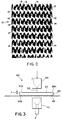
- Figure 3 is a schematic view of apparatus for producing apertured film of the present invention.
- Figure 4 is an exploded perspective view of the starting plastic film and a topographical support backing member on which the starting film is positioned during processing.
- Figure 5 is a diagram of one pattern of apertures of the backing member for producing the films of the present invention.
- Figure 6 is a digitised image of a topographical support member made with the aperture pattern of Figure 5.
- Figure 7 is a schematic view of the apparatus for making the topographical support member.
- Figure 8 is a pixel by pixel diagram of an aperture pattern for making a topographical support member.
- Figure 9 is a block diagram of the process steps for producing the film of the present invention.
- Figure 10 is a diagrammatic view of one type of apparatus for producing apertured film of the present invention.
- Figure 11 is a diagrammatic view of a preferred apparatus for producing apertured film of the present invention.
- Figure 12 is a perspective view of a sanitary napkin comprising the apertured film of the present invention.
- Figure 13 is a partial sectional view taken along lines 13-13, Figure 12.
- Referring now to the drawings, Figure 1 is a perspective view and Figure 2 is a photomicrograph of an apertured plastic film having a tricot-like texture in accordance with the present invention.
- The
film 10 has a plurality of wales orridges 12. Theridges 12 havesloped side walls 14 extending from the ridges toclusters 16 of irregular micro-holes 18 defined by a network of fiber-like elements orfibrils 20. Theclusters 16 of micro-holes 18 are connected by thefibrils 20 between at least two of thesloped side walls 12. Thefibrils 20 are drawn or stretched portions of the film that are formed during the manufacturing process. Extending in a transverse direction to theridges 12 are a plurality of undulatingribs 22 that are substantially free of holes. As can be seen from Figures 1 and 2, the rows of undulatingribs 22 have a network of thewales 12 branching off from opposite sides of theribs 22. The slopedside walls 14 extend from thewales 12 at variable depths. In addition, theside walls 14 are non-uniform in shape. Thefilm 10 also includes a plurality ofmacro-holes 24 randomly dispersed throughout the film. The area of the macro-holes 24 is substantially larger than the area of the micro-holes 18. - The apertured tricot-
like plastic film 10 shown in Figures 1 and 2 essentially consists of four levels or planes. The first plane is comprised of the plurality ofwales 12, the second plane comprises the slopedside walls 14, the third plane comprises the cluster ofirregular holes 18 withfibrils 20 between them, and the fourth plane comprises ofapertured side walls 14 with variable depths. - Figure 3 is a schematic view showing an apparatus for making apertured plastic films of the present invention.
Apparatus 60 comprises amovable conveyor belt 62 and abacking member 64, placed on top of thebelt 62, to move with the belt. The backingmember 64 has a plurality of openings (not shown in Figure 3) disposed therein, said openings running through the thickness of the backingmember 64 from itsupper surface 65a to itslower surface 65b. The backingmember 64 also has a predetermined topographical design that in combination with a pattern of apertures produces tricot-like characteristics in the apertured film. - Placed on top of the backing
member 64 is a thin, continuous,uninterrupted starting film 67 of thermoplastic polymeric material. This starting film may be vapor permeable or vapor impermeable; it may be embossed or unembossed; it may, if desired, be corona-discharge treated on one or both of its major surfaces or it may be free of such corona discharge treatment. The stretchable film may comprise any thermoplastic polymeric material including, by way of example, polyolefins, such as polyethylene (high, linear low or low density) and polypropylene; copolymers of olefins and vinyl monomers, such as copolymers of ethylene and vinyl-acetate or vinyl chloride; polyamides; polyesters; polyvinyl alcohol and copolymers of olefins and acrylate monomers such as copolymers of ethylene and ethyl acrylate and EMA (ethylenemethylacrylate). Starting film comprising mixtures of two or more such polymeric materials may also be used. The machine direction (MD) and cross direction (CD) elongation of the starting film to be apertured should be at least 100% as determined according to ASTM Test No. D-882 as performed on a Instron test machine run at a jaw speed of 50 inches/minute (127 cm/minute). The thickness of the starting film (i.e. the film to be apertured) is preferably uniform and may range from about 0.5 to 3 mils or about 0.0005 inch (0.0013 cm) to about 0.003 inch (0.076 cm). Co-extruded films can be used as can films which have been modified, e.g. by treatment with a surface active agent. The starting film can be made by any known technique such as casting, extrusion or blowing. Preferably a 1 mil microembossed film comprising a blend of linear low density polyethylene (LLDPE) and low density polyethylene (LDPE) is used. - Situated above starting
film 67 is a manifold 69 for applying a fluid 63, preferably water, to theupper surface 67a of the starting film as said film, supported on backingmember 64, is moved withconveyor belt 62. The water may be applied at varying pressures. Disposed beneath the conveyor belt is avacuum manifold 70 for removing water which is directed ontoupper surface 67a of startingfilm 67 as it passes undermanifold 69. - In operation, starting
film 67 is placed on backingmember 64 and the film and backing member are passed back and forth under manifold 69 a number of times until the desired apertured film is produced. -
Manifold 69 comprises a plurality of holes which may range in number from about 30 per lineal inch to about 100 per lineal inch. Preferably, the number of holes in the manifold ranges from about 35 per lineal inch to about 50 per lineal inch. The holes are preferably circular in configuration and have diameters ranging from about 0.003 inch (0.0076 cm) to about 0.01 inch (0.0254 cm), preferably 0.005 inch (0.0127 cm) to 0.007 inch (0.018 cm). After the starting film and backing member are passed under manifold 69 a number of times, the application of the water is stopped and the application of vacuum is continued to assist in dewatering the resulting apertured film of the invention. The apertured film is removed from the backing member and dried by any convenient technique such as the application thereto of a warm air flow or by solvent extraction. - Figure 4 is an exploded perspective view of certain parts, i.e. starting
film 67 and to topographical support or backingmember 64, described earlier herein in conjunction with Figure 3. As mentioned earlier, startingfilm 67 comprises a thermoplastic polymeric material or mixture of two or more such polymeric materials and, as illustrated in Figure 4, the film may be embossed or unembossed. Aportion 75 of startingfilm 67 comprisingembossments 76, and aportion 77 ofunembossed film 67 are shown in the upper portion of Figure 4. - The backing or
topographical support member 64 comprises abody 65 having atop surface 66 andbottom surface 67. Disposed in a predetermined pattern acrosstop surface 66 is an array ofpeaks 68 separated byvalleys 69. A plurality ofdrainage apertures 70 extending through the support member are disposed in a pattern in themember 64. In this embodiment, eachdrainage aperture 70 is surrounded by a cluster of sixpeaks 68 and sixvalleys 69. - The drainage apertures 70 are tapered, or "bell mouthed", having a larger diameter at the top surface of the support member than the bottom surface.
Lines 71 are drawn tangent to opposed points onwalls 72 one hole radius belowtop surface 66. Theangle 73 formed bylines 71 must be controlled relative to thethickness 74 of thesupport member 64 to produce the intended result. A suitable angle can be established without undue experimentation. For example, if the angle is too great, theapertures 70 will be too small and insufficient drainage will be provided. If the angle is too small, there will be very few or no peaks and valleys. - The center-to-center spacing of adjacent apertures in the repeating pattern is of similar importance. The
peaks 68 andvalleys 69 are created by the intersection of the tapered somewhatconical apertures 70. If the center-to-center spacing of the apertures were greater than the major diameter ofaperture 70 at thetop surface 66, no intersection would result, and the member would be a smooth, flat top surface with conical apertures disposed throughout. When the center-to-center spacing of adjacent apertures is less than the aperture diameters measured along that center-to-center line, the conical surfaces intersect forming a valley. - Figure 5 is a diagram showing an example of one pattern of
drainage apertures 70 used for a topographical support member. In this exemplary embodiment, there are two sizes of openings that are used to make up pairs of apertures in rows in the cross direction. The pairs are staggered in the machine direction (MD). The pairs are made up of a row of holes having a size A and a row of holes having a size B, where A is larger than B. The spacing C between pairs of A, B rows is greater than the spacing D between the A and B rows. - Figure 6 is a digitized image of the forming
member 64 shown in Figure 4 that was fabricated using the hole pattern of Figure 5. The holes of sizes A and B are shown with their respective dimensions of peak to valley heights and peak-to-peak spacing. - A preferred apparatus for producing the topographical support member of Figure 4 is shown in Figure 7. The starting material for the support member may be any desired shape or composition. The topographical support member preferably comprises acetal; acrylic will also perform satisfactorily. In addition, the preferred shape of the starting material is a thin wall, cylindrical, preferably seamless, tube that has been relieved of residual internal stresses. As will be described later, the cylindrical shape accommodates the preferred apparatus for producing the apertured films of the invention.
- Tubes manufactured to date for use in forming support members are 2 to 6 feet in diameter and have a length ranging from 2 to 16 feet. The wall thickness is nominally ¼ inch. These sizes are a matter of design choice.
- A starting blank
tubular workpiece 80 is mounted on an appropriate arbor, ormandrel 81 that fixes it in a cylindrical shape and allows rotation about its longitudinal axis inbearings 82. Arotational drive 83 is provided to rotatemandrel 81 at a controlled rate.Rotational pulse generator 84 is connected to and monitors rotation ofmandrel 81 so that its precise radial position is known at all times. - Parallel to and mounted outside the swing of
mandrel 81 is one ormore guide ways 85 that allowcarriage 86 to traverse the entire length ofmandrel 81 while maintaining a constant clearance to thetop surface 9 oftube 80. Carriage drive 93 moves the carriage alongguide ways 85, while carriage pulse generator 94 notes the lateral position of the carriage with respect to supportmember 80. Mounted on the carriage is focusingstage 87. Focusingstage 87 is mounted in focus guideways 88 and allows motion orthogonal to that ofcarriage 86 and provides a means of focusinglens 89 relative top surface oftube 80.Focus drive 92 is provided to position the focusingstage 87 and provide the focusing oflens 81. - Secured to focusing
stage 87 is thelens 89, which is secured innozzle 90.Nozzle 90 has means 91 for introducing a pressurized gas intonozzle 90 for cooling and maintaining cleanliness oflens 89. - Also mounted on the
carriage 86 isfinal bending mirror 95, which directs thelaser beam 96 to the focusinglens 89. Remotely located is thelaser 97, with optional beam bending mirrors 98 to direct the beam to finalbeam bending mirror 95. While it would be possible to mount thelaser 97 directed oncarriage 86 and eliminate the beam bending mirrors, space limitations and utility connections to the laser make remote mounting far preferable. - When the
laser 97 is powered, thebeam 96 emitted is reflected first offbeam bending mirror 98, then finalbeam bending mirror 95, which directs it tolens 89. The path oflaser beam 96 is configured such that, iflens 89 were removed, the beam would pass through the longitudinal center line ofmandrel 81. - With
lens 89 in position, the beam is focused below, but near thetop surface 9 oftube 80. Focusing the beam below the top of surface is identified as "defocusing" the laser beam relative to the surface of the tube. - While this invention could be used with a variety of lasers, the preferred laser is a fast flow CO₂ laser, capable of producing a beam rated at up to 2500 watts. This process is in no way dependent on such a high power laser, as support surfaces have been successfully drilled with a slow flow CO₂ laser limited to 50 watts.
- When focusing
lens 89passes beam 96, it concentrates the energy near the center of the beam. The rays are not bent through a single point, but rather a spot of small diameter. The point of smallest diameter is said to be the focus or focal point. This occurs at a distance from the lens said to be the focal length. At lengths either shorter or greater than the focal length, measured spot sizes will be greater than the minimum. - The sensitivity to focus position is inversely proportional to focal length. Minimum spot size is directly proportional to focal length. Therefore, a short focal length lens can achieve a smaller spot size but must be more accurately positioned and is affected dramatically by surface run-out. Longer focal length lenses are more forgiving of target positioning, but can only achieve somewhat larger spot sizes. Thus, in addition to the power distribution contributing to the tapered top portion of the drilled aperture, the defocusing of the beam below the surface also contributes to the angle and length of the taper, and hence the shape and size of the peaks and valleys.
- In order to fabricate a support member, an initial focusing step must be performed. Once a blank
tubular workpiece 80 is positioned on themandrel 81, the laser is pulsed briefly and the mandrel rotated slightly between pulses such that a series of small depressions is produced. Thefocus stage 87 is then moved with respect to the mandrel center line to change the focus position and another series of depressions is produced. Typically a matrix of 20 rows of 20 depressions each is drilled. The depressions are examined microscopically, and the column of smallest depressions identified. This is established as the reference diameter fortop surface 9 of the blanktubular workpiece 80 at which the beam was focused. - A desired pattern is selected, such as the one shown in Figure 5. The pattern is examined to determine the number of repeats that will be required to cover the circumference of the workpiece and complete the surface without an obvious seam. Similarly, the advance along the longitudinal axis of the tubular workpiece per repeat and total number of repeats is established. These data are entered into a computer control for operating the laser drilling machine.
- In operation, the mandrel, with the tubular workpiece mounted thereon, is rotated in front of the lens. The carriage is motored so that the first aperture position corresponds with the focal point of the
lens 89. The focus stage is motored inward, placing the focal point inside the interior of the material to be drilled. The laser is then pulsed, with some combination of pulse power level and duration. As seen in Figure 4, the diameter ofaperture 70 at thetop surface 66 is considerably larger than the diameter of the aperture at thelower surface 67. In order to achieve the desired topographical configuration, two factors need to be measured and controlled. First, the degree with which the lens is focused into the interior of the workpiece increases thecone angle 73, and second, increasing the power level or pulse duration increases the depth and diameter. Once an aperture of the proper diameter and taper is achieved, the rotational drive and carriage drive can be indexed to reposition the support member such that the next intended hole position corresponds to the focal point. The process is then repeated until the entire pattern has been drilled. This technique is known as "percussion" drilling. - If the laser selected is of sufficient power, the mandrel and carriage do not need to be stopped during the laser pulse. The pulse can be of such short duration that any movement of the workpiece during the drilling process is inconsequential. This is known in the trade as "fire-on-the-fly" drilling.
- If the laser can recover rapidly enough, the workpiece can be rotated at a fixed speed and the laser pulsed once to create each hole. In a pattern such as the one shown in Figure 5, the laser would normally be pulsed to produce a complete column, the carriage indexed to the next column position and the beam pulsed for the next series of apertures.
- One problem that may occur depending on the type of material and density of the pattern of apertures, is the introduction of a large amount of heat into a small area of the forming surface. Gross distortion, and the loss of pattern registration may result. Under some conditions, major dimensional changes of the part results, and the surface is neither cylindrical nor the right size. In extreme cases, the tube may crack.
- A preferred embodiment of the present invention, which eliminates this problem, uses a process called defocused raster scan drilling.
- In this approach, the pattern is reduced to the smallest
rectangular repeat element 41 as depicted in Figure 8. This repeat element contains all of the information required to produce the pattern in Figure 5. When used like a tile and placed both end-to-end and side-by-side, an overall pattern is the result. - This repeat element is further divided into a grid of smaller rectangular units or "pixels" 42. Though typically square, for some purposes, it is more convenient to employ pixels of unequal proportions.
- Each column of pixels represents one pass of the workpiece past the focal position of the laser. This column is repeated as many times as is required to reach completely around
support member 80. Each pixel where the laser is intended to create a hole is black. Those pixels where the laser is turned off are white. - To begin drilling at the top of the first column of pixels in Figure 8, while the mandrel is turning at a fixed rate, the laser is turned on, maintained et a constant power level for 11 pixels and then switched off. These pixels are counted by the
rotational pulse generator 84 in Figure 7. The laser remains off for the next 14 units. This laser off/on sequence is repeated for the first revolution, at which point the mandrel is back to starting position,carriage drive 93 has repositioned the carriage one unit and the computer is ready to docolumn 43a. - During
column number 43a, the laser has a shorter "on time" (now 9 units) and longer "off time" (now 16 units). The total number of on and off times is a constant based on the pattern height. - This process is repeated until all of the columns have been used over an entire revolution each; in the case of Figure 8, there were 15 revolutions of the mandrel. At this point, the process returns to the instructions in
column 43. - Note that in this approach, each pass produces a number of narrow cuts in the material, rather than a large hole. Because these cuts are precisely registered to line up side-by-side and overlap somewhat, the cumulative effect is a hole. In the pattern of Figure 8, each
hexagonal hole 44 actually requires 7 passes separated by a complete revolution, distributing the energy around the tube and minimizing local heating. - If, during this drilling operation, the lens was focused at the top surface of the material, the result would be hexagonal holes with reasonably parallel walls. The combination of raster scan drilling with the defocused lens approach, however, produces the forming surface of Figure 4.
- In the present invention, the
apertures 70 are quite small and numerous. Typical patterns range from 800 to 1400 apertures per square inch. - Figure 9 is a block diagram showing the several steps in the process for producing the novel apertured films of the present invention. The first step in the process is to position a piece of thin, stretchable film of thermoplastic polymer materials on a support member (Box 1). The support member with the stretchable film thereon is passed under high pressure fluid ejecting nozzles (Box 2). The preferred fluid is water. The water is transported away from the support member, preferably using a vacuum (Box 3). The film is dewatered, suction being preferred for this purpose (Box 4). The de-watered apertured film is removed from the support member (Box 5). Residual water is removed from the apertured film, e.g. by applying a stream of air thereto (Box 6). The apertured film is then rolled up to await use as is or as a structural component of another product such as a sanitary napkin, disposable diaper or wound dressing (Box 7).
- Figure 10 is a diagrammatic view of an apparatus for continuously producing the apertured films of the present invention.
Apparatus 90 comprises a backing member provided in the form of aconveyor belt 91.Conveyor belt 91 is continuously moved in a counterclockwise direction about a pair of spaced apartrollers conveyor belt 91 is afluid supply manifold 95 connecting a plurality of lines orgroups 96 of orifices. Eachgroup 96 of orifices includes at least one row of very small diameter holes, there being thirty or more of such holes per lineal inch in each row.Manifold 95 is equipped withpressure gauges 97 andcontrol valves 98 for regulating the fluid pressure in each line or group of orifices. Means (not illustrated in the drawings) are provided for supplying water at an elevated temperature tomanifold 95. Disposed beneath each orifice line or group is asuction member 99 for removing excess water during processing and to keep the aperturing zone from flooding. The startingfilm 67 to be formed into theapertured film 68 of the invention is fed to the conveyor belt comprising the backing member. The starting film passes under thegroup 96 of orifices where it is exposed to the columnar streams of water being ejected from the orifices. The pressure of the water columns being ejected from theindividual groups 96 of orifices can be set bypressure control valves 98 to any desired pressure. The pressure of the water supplied to thegroups 96 of orifices should be at least about 500 psig and may range up to 1500 psig or even higher. In the process for making apertured films of the present invention, it is preferred that theindividual groups 96 of orifices eject water at the same pressure. Though six fluid supplying groups of orifices are shown in Figure 21, the number ofgroups 96 of orifices is not critical, but will depend on the thickness of the starting film, the speed of the conveyor belt, the pressures employed, the number of rows of orifices in eachgroup 96 of orifices, etc. After passing between the columnar water jets andsuction manifold 99, theapertured film 68 passes over anadditional suction slot 99a to remove excess processing water therefrom. The conveyor belt comprising the backing member may be made from relatively rigid material and may comprise a plurality of slats. Each slat extends across the width of the conveyor and has a lip on one side and a slat engages the lip of an adjacent slat to allow for movement between adjacent slats and to allow for these relatively rigid slat members to be employed in the conveyor configuration shown in Figure 21. Alternatively, the backing member may be a woven screen having high points which support the film and low points into which the film is moved during processing. - Referring to Figure 11, there is shown a preferred apparatus for making apertured films of the present invention. Apparatus 100 comprises a
rotatable drum 101. The drum has a honey-comb structure to allow for the passage of fluids therethrough, rotates in a counterclockwise direction and carries a backing member in the form of an elongated cylinder orsleeve 103 placed over its outer surface. Disposed about a portion of the periphery of the drum is a manifold 105 connecting a plurality of orifice strips 106 for applying water to a stretchable thermoplastic starting film 107 carried on the outer surface ofsleeve 103. Each orifice strip comprises a row of very fine uniform circular holes. The diameter of these holes should range from approximately 0.005 inch (0.0127 cm) to 0.010 inch (0.0254 cm). There may be as many as 50 or 60 holes per lineal inch or more if desired. Water is directed under pressure through the orifices, forming columnar streams which impinge on the upper surface of the starting film in a contact or aperturing zone below the orifice strips. The distance from the orifice strips to the upper surface of film 107 being processed is about 0.75 inch (1.90 cm.). The pressure of the water supplied to the orifice strips is controlled bypressure control valves 109, the pressure being indicated bypressure gauges 110. The drum is connected to apump 112 to which a vacuum may be applied to aid in removing water so as to keep the aperturing zone from flooding. In operation, the starting film 107 is placed on thebacking member 103 and passed counter-clockwise under the water ejecting orifice strips 106. As film 107 passes underneath the orifice strips, it is formed into the apertured film of the invention. - The apertured tricot-like plastic film of the present invention has a micro-hole size that is under 25 mils equivalent hydraulic diameter (EHD) and equivalent circular diameter (ECD). The ECD data are obtained from an image analyzer and is calculated in accordance with the following formula:


- An apertured film of the present invention was made by processing a starting film on the apparatus of Figure 11. The starting film comprised a 40:60 (wt%) blend of commercially available low density polyethylene and linear low density polyethylene. The starting film had a thickness of 0.8 mil and was embossed with a diamond pattern having 165 lines per inch. Only 3 of the orifice strips 106 in the apparatus of Figure 11 were employed. Water at 160°F was supplied to the three orifice strips at a pressure of 1350 psig. The line speed of the apparatus was 50 yards/minute. The
sleeve 103 had the topographical configuration shown in Figure 4. The resulting apertured film has an open area of 10%. The average ECD of the micro-holes in the final film was 5 mils. The COV of the ECD of the micro-holes was 58%. The Frazier air permeability of the apertured film was 350 cubic feet/minute/sq. ft. of film. - Example 1 was repeated except that the starting film had a thickness of 0.95 mil and the pressure at which water was supplied to the three orifice strips was 1200 psig. The resulting apertured film had an open area of 5%. The average ECD of the micro-holes in the film was 3 mils. The COV of the ECD of the micro-holes was 62%. There were 6,300 micro-holes per square inch and all of the micro-holes had an EHD under 25 mils.
- The films produced in the above examples were lint free films suitable for use as a wiping cloth or pouch cover. In addition, the film structure did not have interstices to entrap fluid which provides clean/dry properties. The films had good aesthetics, fabric feel, efficient fluid transport and softness.
- The apertured films of the present invention may be used as facing materials for absorbent products such as disposable diapers, sanitary napkins, wound dressings, incontinent devices and the like.
- When used as covering materials for sanitary napkins, it is preferred that the micro-holes of the apertured thermoplastic films of the present invention be sufficient in number to provide an open area ranging from about 1 to 15%, with the number of larger-sized holes preferably being minimized. It is preferred that at least fifty percent (50%) of the micro-holes comprising the film have EHD's ranging between 0.5 and 25 mils. The COV of EHD of the micro-holes is preferably at least 50%. Preferably, at least seventy-five percent (75%) of the micro-holes have areas less than 400 square mils and the coefficient of variation of micro-hole area should be at least 100%.
- Referring to Figures 12 and 13, there is shown a
sanitary napkin 200 comprising anabsorbent core 202 of wood pulp fibers, a thin, fluid-impermeable barrier film 204 and a coveringmaterial 206 which may be any of the apertured films of the invention. Preferably, the covering material has the structure shown and described herein with reference to Figures 1 and 2.Barrier film 204, which may comprise, e.g. a thin film of polyethylene, contacts the lower surface ofabsorbent core 202 and runs part way up the longitudinal sides of the absorbent core. Coveringmaterial 206 has a length somewhat longer than the length of the absorbent core and is wrapped around the absorbent core and barrier film as shown in Figure 13. The longitudinal edges of the cover material are overlapped and sealed together on the lower surface of the napkin in the usual manner. In the embodiment illustrated, the cover material is sealed to itself at theends sanitary napkin 200 has a layer ofadhesive 212 for adhering the napkin to the undergarment of the user.Adhesive 212 is protected prior to use by aremovable release strip 214. - While several embodiments and variations of the present invention are described in detail herein, it should be apparent that the disclosure and teachings of the present invention will suggest many alternative designs to those skilled in the art.
Claims (32)
- An apertured plastic film (10) having a tricot-like texture comprising:
a plurality of wales (12);
a plurality of sloped side walls (14) extending from each wale (12); and
a plurality of clusters (16) of irregular micro-holes (18) defined by a network of fiber-like elements (20), each cluster (16) of irregular micro-holes (18) being connected between at least two of said sloped side walls (14), each of said wales (12), side walls (14) and fiber-like elements (20) being integrally formed of stretchable thermoplastic polymeric material. - The apertured film of Claim 1 wherein each of said plurality of wales extends in a first direction and wherein said film further includes a plurality of rows of undulating ribs (22) extending in a second direction transverse to said first direction.
- The apertured film of Claim 2 wherein each of said rows of undulating ribs (22) has a network of said wales (12) connected to opposite sides of said ribs (22).
- The apertured film of Claim 1 further comprising a plurality of macro-holes (24) randomly dispersed throughout said film.
- The apertured film of Claim 4 wherein said macro-holes (24) are located on said wales (12) and on said sloped side walls (14) at variable depths.
- The apertured film according to Claim 1 wherein said fiber-like elements (20) have been drawn.
- The apertured film according to Claim 6 wherein said fiber-like elements (20) have been drawn at least 100% as compared to adjacent regions of said film which do not contain holes (18).
- The apertured film according to Claim 1 wherein said micro-holes (18) have an area ranging from about 1 square mil to about 100 square mils.
- The apertured film according to Claim 1 wherein the micro-holes (18) have an EHD of less than 25 mils.
- The apertured film according to Claim 1 having an open area of from about 5% to about 12%, said open area being provided by said micro-holes (18).
- The apertured film according to Claim 1 wherein the fiber-like elements (20) have lengths ranging from about 3 mils to about 15 mils with a preferred range from about 5 mils to 7 mils.
- The apertured film according to Claim 1 wherein the fiber-like elements (20) have widths ranging from about 1 mil to 10 mils.
- An apertured film according to Claim 1 wherein the fiber-like elements (20) have thicknesses ranging from about 2 mils to 10 mils with a preferred range from about 4 mils to 8 mils.
- The apertured film of Claim 1 wherein the micro-hole (18) has an ECD of less than 25 mils.
- The apertured film of Claim 1 wherein the micro-holes (18) have an average ECD ranging from about 2 to 7 mils.
- The apertured film of Claim 1 wherein the number of micro-holes (18) range from about 4,000 to 7,000 per square inch.
- The apertured film of Claim 1 wherein the number of wales (12) range from about 2,000 to 6,000 per square inch.
- The apertured film of Claim 1 wherein the micro-holes (18) have a coefficient of variation of ECD greater than 40% with a preferred range from about 50 to 70%.
- A method for forming an apertured film having a tricot-like texture of comprising the steps of:(a) providing a starting film (67) comprising stretchable thermoplastic polymeric material and having an upper surface and a lower surface;(b) providing a backing member (64) comprising a pattern of a plurality of peaks (68) and valleys (69) and a plurality of apertures (70), each of said apertures (70) having a conical top portion surrounded by a cluster of said peaks (68) and valleys (69);(c) supporting said starting film (67) on said backing member (64) with the lower surface of said film being in contact with the peaks (68) of said backing member (64) and with the upper surface of said film facing away from said backing member (64);(d) directing a fluid force against the upper surface of said starting film (67) in a zone of contact and at a pressure sufficient to cause the formation of an apertured film having a plurality of wales (12), a plurality of micro-holes (18) and a plurality of sloped side walls (14) extending between said wales (12) and micro-holes (18) at variable depths;(e) moving said film from said contact zone; and(f) removing said apertured film from said backing member (64).
- A method according to Claim 19 wherein said fluid is directed at the upper surface of said film in the form of columnar streams.
- A method according to Claim 19 wherein said fluid is under pressure ranging from about 500 psig to about 1,600 psig.
- A method according to Claim 19 wherein said fluid is water which is directed at the upper surface of said film at a temperature of at least about 90°F.
- A method according to Claim 22 wherein said water is under pressure ranging from about 500 psig to about 1,600 psig.
- An absorbent product comprising an absorbent core covered with an apertured film, said apertured film comprising a tricot-like film having a plurality of wales (12), a plurality of micro-holes (18) and a plurality of sloped side walls (14) extending between said wales (12) and micro-holes (18) at variable depths.
- An absorbent product according to Claim 24 which is a wound dressing.
- An absorbent product according to Claim 24 wherein both major surfaces to said absorbent core (202) are covered with said apertured film.
- An absorbent product according to Claim 24 which is a disposable diaper.
- An absorbent product according to Claim 24 which is a sanitary napkin.
- An absorbent product according to Claim 27 or 28 further comprising a liquid impervious backing layer (204) located adjacent one major surface of said absorbent core (202).
- An apparatus for producing an apertured film having a tricot-like texture comprising:
a rotatable hollow drum (101) having a top surface comprising a pattern of a plurality of peaks (105) and valleys (106) and a plurality of apertures (107), each of said apertures (107) having a conical top portion surrounded by a cluster of said peaks (105) and valleys (106);
means for positioning a stretchable thermoplastic polymer film on the apices of the peaks (105) on the top surface of the drum (101);
means (106) located outside the drum (101) for projecting adjacent fluid streams simultaneously against said film and then against the peaks (105) and then through the openings (107) and into the drum (101);
means (83) for rotating said drum (101) while said fluid is being projected against said top surface;
means (112) disposed inside the drum (101) to remove the fluid from the surface of the drum (101); and
means for removing said apertured film (108) having a tricot-like texture from the surface of the drum (101). - The apertured film of Claim 1 wherein said sloped side walls (14) extend at variable depths below said wales (12).
- The apertured film of Claim 1 wherein said side walls (14) are non-uniform in shape.
Applications Claiming Priority (2)
| Application Number | Priority Date | Filing Date | Title |
|---|---|---|---|
| US30797394A | 1994-09-16 | 1994-09-16 | |
| US307973 | 1994-09-16 |
Publications (2)
| Publication Number | Publication Date |
|---|---|
| EP0701805A1 true EP0701805A1 (en) | 1996-03-20 |
| EP0701805B1 EP0701805B1 (en) | 1999-08-04 |
Family
ID=23191982
Family Applications (1)
| Application Number | Title | Priority Date | Filing Date |
|---|---|---|---|
| EP95114562A Expired - Lifetime EP0701805B1 (en) | 1994-09-16 | 1995-09-15 | Apertured plastic film |
Country Status (24)
| Country | Link |
|---|---|
| US (1) | US5824352A (en) |
| EP (1) | EP0701805B1 (en) |
| JP (1) | JP3763870B2 (en) |
| KR (1) | KR960010027A (en) |
| CN (1) | CN1262258C (en) |
| AT (1) | ATE182777T1 (en) |
| AU (1) | AU711000B2 (en) |
| BR (1) | BR9504038A (en) |
| CA (1) | CA2157729C (en) |
| CZ (1) | CZ291665B6 (en) |
| DE (1) | DE69511192T2 (en) |
| ES (1) | ES2134981T3 (en) |
| FI (1) | FI954358A (en) |
| GR (1) | GR3031431T3 (en) |
| HK (1) | HK1010326A1 (en) |
| HU (1) | HU215765B (en) |
| IL (1) | IL115285A0 (en) |
| NO (1) | NO302834B1 (en) |
| NZ (1) | NZ272887A (en) |
| RU (1) | RU2150387C1 (en) |
| SG (1) | SG54974A1 (en) |
| TR (1) | TR199501110A2 (en) |
| TW (1) | TW355678B (en) |
| ZA (1) | ZA957814B (en) |
Cited By (6)
| Publication number | Priority date | Publication date | Assignee | Title |
|---|---|---|---|---|
| EP0862904A3 (en) * | 1997-01-31 | 1999-04-21 | Uni-Charm Corporation | Liquid-permeable topsheet in disposable body fluids absorbent article |
| EP0809680B2 (en) † | 1995-02-17 | 2003-05-07 | McNEIL-PPC, INC. | Use of heat-sealable films that are degradable for disposal products and absorbent products containing these films |
| WO2004058460A1 (en) * | 2002-12-20 | 2004-07-15 | The Procter & Gamble Company | Apparatus for making a polymeric web exhibiting a soft and silky tactile impression |
| EP1493416A2 (en) * | 2003-07-02 | 2005-01-05 | Tredegar Film Products Corporation | Flexible form fitting web |
| US7601415B2 (en) | 2001-12-03 | 2009-10-13 | Tredegar Film Products Corporation | Absorbent device using an apertured nonwoven as an acquisition distribution layer |
| US9833017B2 (en) | 2012-07-25 | 2017-12-05 | R.J. Reynolds Tobacco Company | Mixed fiber sliver for use in the manufacture of cigarette filter elements |
Families Citing this family (38)
| Publication number | Priority date | Publication date | Assignee | Title |
|---|---|---|---|---|
| US5770144A (en) * | 1995-09-01 | 1998-06-23 | Mcneil-Ppc, Inc. | Method of forming improved apertured films by using fluid perforation |
| US6306237B1 (en) * | 1995-11-28 | 2001-10-23 | Roy D. Wemyss | Lamination of surfaces using pressurized liquid |
| US6024553A (en) | 1997-12-22 | 2000-02-15 | Mcneil-Ppc, Inc. | Apparatus for supporting a starting web during formation of the apertured web |
| WO2000059436A1 (en) * | 1999-04-01 | 2000-10-12 | The Procter & Gamble Company | Improved resilient, three dimensional polymeric film with slanted capillary apertures, and absorbent article with backsheet comprising the film |
| EP1040805A1 (en) * | 1999-04-01 | 2000-10-04 | The Procter & Gamble Company | Resilient, three dimensional polymeric film comprising capillary apertures |
| EP1040807A1 (en) * | 1999-04-01 | 2000-10-04 | The Procter & Gamble Company | Absorbent article with improved backsheet comprising capillary apertures |
| AU4191200A (en) * | 1999-04-01 | 2000-10-23 | Procter & Gamble Company, The | Resilient, three dimensional polymeric film comprising capillary apertures, and absorbent article with improved backsheet comprising the film |
| EP1040801A1 (en) * | 1999-04-01 | 2000-10-04 | The Procter & Gamble Company | Improved resilient, three dimensional polymeric film with slanted capillary apertures |
| EP1040802A1 (en) * | 1999-04-01 | 2000-10-04 | The Procter & Gamble Company | Absorbent article with slanted capillaries apertured backsheet |
| NL1014769C2 (en) * | 2000-03-28 | 2001-10-01 | Stork Screens Bv | Metal perforation template, method for the manufacture thereof, as well as application. |
| JP3877953B2 (en) | 2000-10-31 | 2007-02-07 | ユニ・チャーム株式会社 | Non-woven surface sheet for disposable wearing articles |
| US6942894B2 (en) | 2001-11-05 | 2005-09-13 | 3M Innovative Properties Company | Methods for producing composite webs with reinforcing discrete polymeric regions |
| US7037457B2 (en) | 2001-11-05 | 2006-05-02 | 3M Innovative Properties Company | Systems and methods for composite webs with structured discrete polymeric regions |
| US6763875B2 (en) | 2002-02-06 | 2004-07-20 | Andersen Corporation | Reduced visibility insect screen |
| CN100346923C (en) * | 2002-02-14 | 2007-11-07 | 麦克内尔-Ppc股份有限公司 | Method of mfg. floor supporting part for forming porous film |
| US8287800B2 (en) * | 2002-12-20 | 2012-10-16 | The Procter And Gamble Company | Method for making a polymeric web exhibiting a soft and silky tactile impression |
| US7655176B2 (en) * | 2002-12-20 | 2010-02-02 | The Procter & Gamble Company | Method of making a polymeric web exhibiting a soft and silky tactile impression |
| US7402723B2 (en) * | 2002-12-20 | 2008-07-22 | The Procter & Gamble Company | Polymeric web exhibiting a soft and silky tactile impression |
| US9545744B2 (en) | 2002-12-20 | 2017-01-17 | The Procter & Gamble Company | Apparatus for making polymeric web exhibiting a soft and silky tactile impression |
| US20070125756A1 (en) * | 2003-02-10 | 2007-06-07 | Kelly William G | Method of making topographical support members for producing apertured films |
| US20050025936A1 (en) * | 2003-04-11 | 2005-02-03 | Jerry Snider | Nonwoven cleaning articles having intercalated three-dimensional images |
| US7105716B2 (en) * | 2003-12-31 | 2006-09-12 | Kimberly-Clark Worldwide, Inc. | Absorbent articles |
| US20060178652A1 (en) * | 2005-02-09 | 2006-08-10 | Miller Robert A Iii | Incontinence pad and apparel formed therewith |
| FR2885915B1 (en) * | 2005-05-20 | 2007-08-03 | Rieter Perfojet Sa | DRUM FOR MANUFACTURING MACHINE OF A NON-WOVEN PATTERN AND NON-WOVEN FABRIC |
| US8158043B2 (en) * | 2009-02-06 | 2012-04-17 | The Procter & Gamble Company | Method for making an apertured web |
| JP2011131044A (en) * | 2009-11-24 | 2011-07-07 | Kao Corp | Absorbent article |
| US20120288692A1 (en) * | 2011-04-12 | 2012-11-15 | Norman Scott Broyles | Renewably sourced films and methods of forming same |
| US9724245B2 (en) * | 2011-04-26 | 2017-08-08 | The Procter & Gamble Company | Formed web comprising chads |
| PL2567682T5 (en) | 2011-09-09 | 2018-06-29 | Paul Hartmann Ag | Abdominal wound dressing with application aid |
| US9861533B2 (en) | 2013-05-08 | 2018-01-09 | The Procter & Gamble Company | Apertured nonwoven materials and methods for forming the same |
| EP3215086B1 (en) | 2014-11-06 | 2020-03-18 | The Procter and Gamble Company | Crimped fiber spunbond nonwoven webs / laminates |
| CN107106380A (en) | 2014-11-06 | 2017-08-29 | 宝洁公司 | Absorbent article with color effect |
| CN107106342B (en) | 2014-11-06 | 2020-09-15 | 宝洁公司 | Apertured web and method of making same |
| KR101897427B1 (en) * | 2014-12-19 | 2018-09-10 | 킴벌리-클라크 월드와이드, 인크. | Nonwoven apertured elastic film with improved bonding features |
| US10335973B2 (en) * | 2015-12-11 | 2019-07-02 | Tredegar Film Products Corporation | Hydro-formed film with three-dimensional micro-apertures |
| WO2017213675A1 (en) | 2016-06-10 | 2017-12-14 | Tredegar Film Products Corporation | Hydroformed expanded spun bonded nonwoven web and hydroformed composite material, and methods for making same |
| WO2018152272A1 (en) | 2017-02-16 | 2018-08-23 | The Procter & Gamble Company | Absorbent articles with substrates having repeating patterns of apertures comprising a plurality of repeat units |
| WO2020219414A1 (en) | 2019-04-24 | 2020-10-29 | The Procter & Gamble Company | Highly extensible nonwoven webs and absorbent articles having such webs |
Citations (8)
| Publication number | Priority date | Publication date | Assignee | Title |
|---|---|---|---|---|
| US3632269A (en) | 1969-02-14 | 1972-01-04 | Johnson & Johnson | Appratus for producing a plastic net product |
| US3929135A (en) | 1974-12-20 | 1975-12-30 | Procter & Gamble | Absorptive structure having tapered capillaries |
| US4324276A (en) | 1978-07-22 | 1982-04-13 | Robert Bosch Gmbh | Noise damping device |
| US4381326A (en) | 1977-11-03 | 1983-04-26 | Chicopee | Reticulated themoplastic rubber products |
| US4690679A (en) | 1986-03-14 | 1987-09-01 | Johnson & Johnson | Coextruded apertured film sanitary napkin cover |
| EP0304617A2 (en) | 1987-07-30 | 1989-03-01 | Kao Corporation | Sanitary article |
| US4839216A (en) | 1984-02-16 | 1989-06-13 | The Procter & Gamble Company | Formed material produced by solid-state formation with a high-pressure liquid stream |
| WO1993015701A1 (en) * | 1992-02-18 | 1993-08-19 | Chicopee | Textile-like apertured plastic films |
Family Cites Families (23)
| Publication number | Priority date | Publication date | Assignee | Title |
|---|---|---|---|---|
| GB1262853A (en) * | 1968-02-14 | 1972-02-09 | Plasticisers Ltd | Fibrillators |
| US3566735A (en) * | 1969-02-12 | 1971-03-02 | Phillips Petroleum Co | Fibrillation |
| US3596816A (en) * | 1969-05-05 | 1971-08-03 | Phillips Petroleum Co | Fibrillation method |
| US3819775A (en) * | 1972-08-15 | 1974-06-25 | R Mules | Method of making polymeric film |
| US4377544A (en) * | 1974-12-10 | 1983-03-22 | Rasmussen O B | Manufacture of a textile-like reticular product from thermoplastic film |
| US4287249A (en) * | 1975-02-28 | 1981-09-01 | General Electric Company | Textured surface polypropylene film |
| US4151240A (en) * | 1976-10-19 | 1979-04-24 | The Procter & Gamble Company | Method for debossing and perforating a running ribbon of thermoplastic film |
| GB1603865A (en) * | 1977-07-08 | 1981-12-02 | Smith & Nephew Plastics | Production of net |
| US4272473A (en) * | 1978-12-07 | 1981-06-09 | The Procter & Gamble Company | Method for embossing and perforating a running ribbon of thermoplastic film on a metallic pattern roll |
| US4324246A (en) * | 1980-05-12 | 1982-04-13 | The Procter & Gamble Company | Disposable absorbent article having a stain resistant topsheet |
| US4509908A (en) * | 1981-02-02 | 1985-04-09 | The Procter & Gamble Company | Apparatus for uniformly debossing and aperturing a resilient plastic web |
| US4552709A (en) * | 1983-11-04 | 1985-11-12 | The Procter & Gamble Company | Process for high-speed production of webs of debossed and perforated thermoplastic film |
| US4695422A (en) * | 1984-02-16 | 1987-09-22 | The Procter & Gamble Company | Production of formed material by solid-state formation with a high-pressure liquid stream |
| US4591523A (en) * | 1985-05-31 | 1986-05-27 | The Procter & Gamble Company | Apertured macroscopically expanded three-dimensional polymeric web exhibiting breatheability and resistance to fluid transmission |
| US4609518A (en) * | 1985-05-31 | 1986-09-02 | The Procter & Gamble Company | Multi-phase process for debossing and perforating a polymeric web to coincide with the image of one or more three-dimensional forming structures |
| IT1188132B (en) * | 1986-05-07 | 1987-12-30 | Fameccanica Spa | PROCEDURE AND DEVICE FOR THE PRODUCTION OF PERFORATED FILMS PARTICULARLY PLASTIC PERFORATED FILMS FOR SANITARY SANITARY ITEMS |
| US4772444A (en) * | 1987-08-24 | 1988-09-20 | The Procter & Gamble Company | Method and apparatus for making microbubbled and/or microapertured polymeric webs using hydraulic pressure |
| US5098764A (en) * | 1990-03-12 | 1992-03-24 | Chicopee | Non-woven fabric and method and apparatus for making the same |
| US5244711A (en) * | 1990-03-12 | 1993-09-14 | Mcneil-Ppc, Inc. | Apertured non-woven fabric |
| US5158819A (en) * | 1990-06-29 | 1992-10-27 | The Procter & Gamble Company | Polymeric web exhibiting a soft, silky, cloth-like tactile impression and including a contrasting visually discernible pattern having an embossed appearance on at least one surface thereof |
| US5269981A (en) * | 1991-09-30 | 1993-12-14 | Kimberly-Clark Corporation | Process for hydrosonically microaperturing |
| US5366782A (en) * | 1992-08-25 | 1994-11-22 | The Procter & Gamble Company | Polymeric web having deformed sections which provide a substantially increased elasticity to the web |
| US5441691A (en) * | 1993-09-30 | 1995-08-15 | The Procter & Gamble Company | Process for microaperaturing and microembossing a polymeric web |
-
1995
- 1995-08-29 NZ NZ272887A patent/NZ272887A/en unknown
- 1995-09-07 CA CA002157729A patent/CA2157729C/en not_active Expired - Lifetime
- 1995-09-11 AU AU30579/95A patent/AU711000B2/en not_active Expired
- 1995-09-12 TR TR95/01110A patent/TR199501110A2/en unknown
- 1995-09-13 SG SG1995001352A patent/SG54974A1/en unknown
- 1995-09-13 IL IL11528595A patent/IL115285A0/en unknown
- 1995-09-14 JP JP26102195A patent/JP3763870B2/en not_active Expired - Lifetime
- 1995-09-14 CZ CZ19952380A patent/CZ291665B6/en not_active IP Right Cessation
- 1995-09-14 RU RU95115980/12A patent/RU2150387C1/en active
- 1995-09-15 AT AT95114562T patent/ATE182777T1/en active
- 1995-09-15 EP EP95114562A patent/EP0701805B1/en not_active Expired - Lifetime
- 1995-09-15 BR BR9504038A patent/BR9504038A/en not_active IP Right Cessation
- 1995-09-15 KR KR1019950030173A patent/KR960010027A/en not_active Application Discontinuation
- 1995-09-15 NO NO953655A patent/NO302834B1/en unknown
- 1995-09-15 HU HU9502705A patent/HU215765B/en unknown
- 1995-09-15 ES ES95114562T patent/ES2134981T3/en not_active Expired - Lifetime
- 1995-09-15 DE DE69511192T patent/DE69511192T2/en not_active Expired - Lifetime
- 1995-09-15 ZA ZA957814A patent/ZA957814B/en unknown
- 1995-09-15 FI FI954358A patent/FI954358A/en not_active Application Discontinuation
- 1995-09-16 CN CNB951186078A patent/CN1262258C/en not_active Expired - Lifetime
- 1995-10-16 TW TW084110839A patent/TW355678B/en not_active IP Right Cessation
-
1996
- 1996-11-12 US US08/747,937 patent/US5824352A/en not_active Expired - Lifetime
-
1998
- 1998-09-28 HK HK98111018A patent/HK1010326A1/en not_active IP Right Cessation
-
1999
- 1999-10-07 GR GR990402520T patent/GR3031431T3/en unknown
Patent Citations (8)
| Publication number | Priority date | Publication date | Assignee | Title |
|---|---|---|---|---|
| US3632269A (en) | 1969-02-14 | 1972-01-04 | Johnson & Johnson | Appratus for producing a plastic net product |
| US3929135A (en) | 1974-12-20 | 1975-12-30 | Procter & Gamble | Absorptive structure having tapered capillaries |
| US4381326A (en) | 1977-11-03 | 1983-04-26 | Chicopee | Reticulated themoplastic rubber products |
| US4324276A (en) | 1978-07-22 | 1982-04-13 | Robert Bosch Gmbh | Noise damping device |
| US4839216A (en) | 1984-02-16 | 1989-06-13 | The Procter & Gamble Company | Formed material produced by solid-state formation with a high-pressure liquid stream |
| US4690679A (en) | 1986-03-14 | 1987-09-01 | Johnson & Johnson | Coextruded apertured film sanitary napkin cover |
| EP0304617A2 (en) | 1987-07-30 | 1989-03-01 | Kao Corporation | Sanitary article |
| WO1993015701A1 (en) * | 1992-02-18 | 1993-08-19 | Chicopee | Textile-like apertured plastic films |
Cited By (9)
| Publication number | Priority date | Publication date | Assignee | Title |
|---|---|---|---|---|
| EP0809680B2 (en) † | 1995-02-17 | 2003-05-07 | McNEIL-PPC, INC. | Use of heat-sealable films that are degradable for disposal products and absorbent products containing these films |
| EP0862904A3 (en) * | 1997-01-31 | 1999-04-21 | Uni-Charm Corporation | Liquid-permeable topsheet in disposable body fluids absorbent article |
| US6013348A (en) * | 1997-01-31 | 2000-01-11 | Uni-Charm Corporation | Liquid-permeable topsheet in disposable body fluids absorbent garment |
| US7601415B2 (en) | 2001-12-03 | 2009-10-13 | Tredegar Film Products Corporation | Absorbent device using an apertured nonwoven as an acquisition distribution layer |
| WO2004058460A1 (en) * | 2002-12-20 | 2004-07-15 | The Procter & Gamble Company | Apparatus for making a polymeric web exhibiting a soft and silky tactile impression |
| EP2347872A3 (en) * | 2002-12-20 | 2015-01-14 | The Procter and Gamble Company | Forming structure for making three-dimensional, macroscopically-expanded webs |
| EP1493416A2 (en) * | 2003-07-02 | 2005-01-05 | Tredegar Film Products Corporation | Flexible form fitting web |
| EP1493416A3 (en) * | 2003-07-02 | 2005-11-23 | Tredegar Film Products Corporation | Flexible form fitting web |
| US9833017B2 (en) | 2012-07-25 | 2017-12-05 | R.J. Reynolds Tobacco Company | Mixed fiber sliver for use in the manufacture of cigarette filter elements |
Also Published As
| Publication number | Publication date |
|---|---|
| BR9504038A (en) | 1996-09-24 |
| CZ238095A3 (en) | 1996-04-17 |
| HU215765B (en) | 1999-02-01 |
| SG54974A1 (en) | 1998-12-21 |
| TW355678B (en) | 1999-04-11 |
| CZ291665B6 (en) | 2003-04-16 |
| JP3763870B2 (en) | 2006-04-05 |
| AU3057995A (en) | 1996-03-28 |
| US5824352A (en) | 1998-10-20 |
| JPH08187813A (en) | 1996-07-23 |
| ES2134981T3 (en) | 1999-10-16 |
| EP0701805B1 (en) | 1999-08-04 |
| HUT76306A (en) | 1997-08-28 |
| NO953655D0 (en) | 1995-09-15 |
| CA2157729C (en) | 2006-05-09 |
| NO953655L (en) | 1996-03-18 |
| AU711000B2 (en) | 1999-10-07 |
| CA2157729A1 (en) | 1996-03-17 |
| GR3031431T3 (en) | 2000-01-31 |
| HK1010326A1 (en) | 1999-06-17 |
| CN1262258C (en) | 2006-07-05 |
| CN1130053A (en) | 1996-09-04 |
| ZA957814B (en) | 1997-03-17 |
| FI954358A0 (en) | 1995-09-15 |
| KR960010027A (en) | 1996-04-20 |
| NO302834B1 (en) | 1998-04-27 |
| RU2150387C1 (en) | 2000-06-10 |
| TR199501110A2 (en) | 1996-06-21 |
| HU9502705D0 (en) | 1995-11-28 |
| NZ272887A (en) | 1998-06-26 |
| DE69511192D1 (en) | 1999-09-09 |
| ATE182777T1 (en) | 1999-08-15 |
| IL115285A0 (en) | 1995-12-31 |
| FI954358A (en) | 1996-03-17 |
| DE69511192T2 (en) | 2000-02-24 |
Similar Documents
| Publication | Publication Date | Title |
|---|---|---|
| US5824352A (en) | Apparatus for producing an apertured plastic film having a tricot texture | |
| AU711811B2 (en) | Laser drilling processes for making fabric and film forming devices | |
| EP0705933B1 (en) | Apparatus for making nonwoven fabrics having raised portions | |
| US6660361B1 (en) | Apertured web and an apparatus and process for supporting a starting web during formation of the apertured web | |
| AU704751B2 (en) | Nonwoven fabrics having raised portions | |
| EP0879041B1 (en) | Backing web in an absorbent article | |
| US6240817B1 (en) | Method of forming improved apertured films by using fluid perforation | |
| USRE38505E1 (en) | Nonwoven fabrics having raised portions | |
| RU2311159C2 (en) | Double-layer structure for absorbing articles | |
| CA2513621C (en) | Apparatus for making nonwoven fabrics having raised portions |
Legal Events
| Date | Code | Title | Description |
|---|---|---|---|
| PUAI | Public reference made under article 153(3) epc to a published international application that has entered the european phase |
Free format text: ORIGINAL CODE: 0009012 |
|
| AK | Designated contracting states |
Kind code of ref document: A1 Designated state(s): AT BE CH DE DK ES FR GB GR IT LI NL SE |
|
| 17P | Request for examination filed |
Effective date: 19960830 |
|
| 17Q | First examination report despatched |
Effective date: 19980709 |
|
| GRAG | Despatch of communication of intention to grant |
Free format text: ORIGINAL CODE: EPIDOS AGRA |
|
| GRAG | Despatch of communication of intention to grant |
Free format text: ORIGINAL CODE: EPIDOS AGRA |
|
| GRAH | Despatch of communication of intention to grant a patent |
Free format text: ORIGINAL CODE: EPIDOS IGRA |
|
| GRAH | Despatch of communication of intention to grant a patent |
Free format text: ORIGINAL CODE: EPIDOS IGRA |
|
| GRAA | (expected) grant |
Free format text: ORIGINAL CODE: 0009210 |
|
| AK | Designated contracting states |
Kind code of ref document: B1 Designated state(s): AT BE CH DE DK ES FR GB GR IT LI NL SE |
|
| PG25 | Lapsed in a contracting state [announced via postgrant information from national office to epo] |
Ref country code: SE Free format text: THE PATENT HAS BEEN ANNULLED BY A DECISION OF A NATIONAL AUTHORITY Effective date: 19990804 Ref country code: LI Free format text: LAPSE BECAUSE OF FAILURE TO SUBMIT A TRANSLATION OF THE DESCRIPTION OR TO PAY THE FEE WITHIN THE PRESCRIBED TIME-LIMIT Effective date: 19990804 Ref country code: CH Free format text: LAPSE BECAUSE OF FAILURE TO SUBMIT A TRANSLATION OF THE DESCRIPTION OR TO PAY THE FEE WITHIN THE PRESCRIBED TIME-LIMIT Effective date: 19990804 Ref country code: BE Free format text: LAPSE BECAUSE OF FAILURE TO SUBMIT A TRANSLATION OF THE DESCRIPTION OR TO PAY THE FEE WITHIN THE PRESCRIBED TIME-LIMIT Effective date: 19990804 |
|
| REF | Corresponds to: |
Ref document number: 182777 Country of ref document: AT Date of ref document: 19990815 Kind code of ref document: T |
|
| REG | Reference to a national code |
Ref country code: CH Ref legal event code: EP |
|
| REF | Corresponds to: |
Ref document number: 69511192 Country of ref document: DE Date of ref document: 19990909 |
|
| ITF | It: translation for a ep patent filed |
Owner name: SOCIETA' ITALIANA BREVETTI S.P.A. |
|
| ET | Fr: translation filed | ||
| REG | Reference to a national code |
Ref country code: ES Ref legal event code: FG2A Ref document number: 2134981 Country of ref document: ES Kind code of ref document: T3 |
|
| PG25 | Lapsed in a contracting state [announced via postgrant information from national office to epo] |
Ref country code: DK Free format text: LAPSE BECAUSE OF FAILURE TO SUBMIT A TRANSLATION OF THE DESCRIPTION OR TO PAY THE FEE WITHIN THE PRESCRIBED TIME-LIMIT Effective date: 19991104 |
|
| REG | Reference to a national code |
Ref country code: CH Ref legal event code: PL |
|
| PLBE | No opposition filed within time limit |
Free format text: ORIGINAL CODE: 0009261 |
|
| STAA | Information on the status of an ep patent application or granted ep patent |
Free format text: STATUS: NO OPPOSITION FILED WITHIN TIME LIMIT |
|
| 26N | No opposition filed | ||
| REG | Reference to a national code |
Ref country code: GB Ref legal event code: IF02 |
|
| PGFP | Annual fee paid to national office [announced via postgrant information from national office to epo] |
Ref country code: NL Payment date: 20140910 Year of fee payment: 20 Ref country code: GR Payment date: 20140814 Year of fee payment: 20 Ref country code: DE Payment date: 20140911 Year of fee payment: 20 |
|
| PGFP | Annual fee paid to national office [announced via postgrant information from national office to epo] |
Ref country code: ES Payment date: 20140812 Year of fee payment: 20 Ref country code: AT Payment date: 20140827 Year of fee payment: 20 Ref country code: GB Payment date: 20140910 Year of fee payment: 20 |
|
| PGFP | Annual fee paid to national office [announced via postgrant information from national office to epo] |
Ref country code: IT Payment date: 20140912 Year of fee payment: 20 |
|
| PGFP | Annual fee paid to national office [announced via postgrant information from national office to epo] |
Ref country code: FR Payment date: 20140906 Year of fee payment: 20 |
|
| REG | Reference to a national code |
Ref country code: DE Ref legal event code: R071 Ref document number: 69511192 Country of ref document: DE |
|
| REG | Reference to a national code |
Ref country code: NL Ref legal event code: MK Effective date: 20150914 |
|
| REG | Reference to a national code |
Ref country code: GB Ref legal event code: PE20 Expiry date: 20150914 |
|
| PG25 | Lapsed in a contracting state [announced via postgrant information from national office to epo] |
Ref country code: GB Free format text: LAPSE BECAUSE OF EXPIRATION OF PROTECTION Effective date: 20150914 |
|
| REG | Reference to a national code |
Ref country code: AT Ref legal event code: MK07 Ref document number: 182777 Country of ref document: AT Kind code of ref document: T Effective date: 20150915 |
|
| REG | Reference to a national code |
Ref country code: GR Ref legal event code: MA Ref document number: 990402520 Country of ref document: GR Effective date: 20150916 |
|
| REG | Reference to a national code |
Ref country code: ES Ref legal event code: FD2A Effective date: 20151229 |
|
| PG25 | Lapsed in a contracting state [announced via postgrant information from national office to epo] |
Ref country code: ES Free format text: LAPSE BECAUSE OF EXPIRATION OF PROTECTION Effective date: 20150916 |