EP0701390A2 - Circuit for controlling the light intensity and the operating mode of discharge lamps - Google Patents
Circuit for controlling the light intensity and the operating mode of discharge lamps Download PDFInfo
- Publication number
- EP0701390A2 EP0701390A2 EP95114571A EP95114571A EP0701390A2 EP 0701390 A2 EP0701390 A2 EP 0701390A2 EP 95114571 A EP95114571 A EP 95114571A EP 95114571 A EP95114571 A EP 95114571A EP 0701390 A2 EP0701390 A2 EP 0701390A2
- Authority
- EP
- European Patent Office
- Prior art keywords
- control
- lamp
- circuit
- brightness
- voltage generator
- Prior art date
- Legal status (The legal status is an assumption and is not a legal conclusion. Google has not performed a legal analysis and makes no representation as to the accuracy of the status listed.)
- Withdrawn
Links
- 230000001105 regulatory effect Effects 0.000 claims description 46
- 238000000034 method Methods 0.000 claims description 23
- 230000006399 behavior Effects 0.000 claims description 7
- 230000001276 controlling effect Effects 0.000 claims description 7
- 230000033228 biological regulation Effects 0.000 claims description 4
- 238000002565 electrocardiography Methods 0.000 description 23
- 239000003990 capacitor Substances 0.000 description 20
- 238000010438 heat treatment Methods 0.000 description 19
- 230000008569 process Effects 0.000 description 18
- 238000010586 diagram Methods 0.000 description 12
- 238000012544 monitoring process Methods 0.000 description 11
- 230000008878 coupling Effects 0.000 description 10
- 238000010168 coupling process Methods 0.000 description 10
- 238000005859 coupling reaction Methods 0.000 description 10
- 230000001965 increasing effect Effects 0.000 description 9
- 239000007789 gas Substances 0.000 description 8
- 238000001514 detection method Methods 0.000 description 7
- 238000004804 winding Methods 0.000 description 7
- 230000000694 effects Effects 0.000 description 6
- 230000008859 change Effects 0.000 description 5
- XKRFYHLGVUSROY-UHFFFAOYSA-N Argon Chemical compound [Ar] XKRFYHLGVUSROY-UHFFFAOYSA-N 0.000 description 4
- 230000002457 bidirectional effect Effects 0.000 description 4
- 230000002950 deficient Effects 0.000 description 4
- 238000012423 maintenance Methods 0.000 description 4
- 238000005259 measurement Methods 0.000 description 4
- 238000013016 damping Methods 0.000 description 3
- 230000007547 defect Effects 0.000 description 3
- 230000001419 dependent effect Effects 0.000 description 3
- 230000001939 inductive effect Effects 0.000 description 3
- 229910052786 argon Inorganic materials 0.000 description 2
- 230000006378 damage Effects 0.000 description 2
- 230000007423 decrease Effects 0.000 description 2
- 238000011161 development Methods 0.000 description 2
- 238000009499 grossing Methods 0.000 description 2
- 229910052743 krypton Inorganic materials 0.000 description 2
- DNNSSWSSYDEUBZ-UHFFFAOYSA-N krypton atom Chemical compound [Kr] DNNSSWSSYDEUBZ-UHFFFAOYSA-N 0.000 description 2
- 230000009467 reduction Effects 0.000 description 2
- 230000001629 suppression Effects 0.000 description 2
- 238000011144 upstream manufacturing Methods 0.000 description 2
- 230000000712 assembly Effects 0.000 description 1
- 238000000429 assembly Methods 0.000 description 1
- 230000005540 biological transmission Effects 0.000 description 1
- 230000001934 delay Effects 0.000 description 1
- 230000005611 electricity Effects 0.000 description 1
- 230000008030 elimination Effects 0.000 description 1
- 238000003379 elimination reaction Methods 0.000 description 1
- 125000000524 functional group Chemical group 0.000 description 1
- 230000005415 magnetization Effects 0.000 description 1
- 230000003287 optical effect Effects 0.000 description 1
- 230000008520 organization Effects 0.000 description 1
- 238000002360 preparation method Methods 0.000 description 1
- 238000004904 shortening Methods 0.000 description 1
- 239000007858 starting material Substances 0.000 description 1
- 230000007704 transition Effects 0.000 description 1
- 230000001960 triggered effect Effects 0.000 description 1
Images


Classifications
-
- H—ELECTRICITY
- H05—ELECTRIC TECHNIQUES NOT OTHERWISE PROVIDED FOR
- H05B—ELECTRIC HEATING; ELECTRIC LIGHT SOURCES NOT OTHERWISE PROVIDED FOR; CIRCUIT ARRANGEMENTS FOR ELECTRIC LIGHT SOURCES, IN GENERAL
- H05B41/00—Circuit arrangements or apparatus for igniting or operating discharge lamps
- H05B41/14—Circuit arrangements
- H05B41/36—Controlling
- H05B41/38—Controlling the intensity of light
- H05B41/39—Controlling the intensity of light continuously
- H05B41/392—Controlling the intensity of light continuously using semiconductor devices, e.g. thyristor
- H05B41/3921—Controlling the intensity of light continuously using semiconductor devices, e.g. thyristor with possibility of light intensity variations
- H05B41/3922—Controlling the intensity of light continuously using semiconductor devices, e.g. thyristor with possibility of light intensity variations and measurement of the incident light
-
- H—ELECTRICITY
- H05—ELECTRIC TECHNIQUES NOT OTHERWISE PROVIDED FOR
- H05B—ELECTRIC HEATING; ELECTRIC LIGHT SOURCES NOT OTHERWISE PROVIDED FOR; CIRCUIT ARRANGEMENTS FOR ELECTRIC LIGHT SOURCES, IN GENERAL
- H05B41/00—Circuit arrangements or apparatus for igniting or operating discharge lamps
- H05B41/14—Circuit arrangements
- H05B41/26—Circuit arrangements in which the lamp is fed by power derived from dc by means of a converter, e.g. by high-voltage dc
- H05B41/28—Circuit arrangements in which the lamp is fed by power derived from dc by means of a converter, e.g. by high-voltage dc using static converters
- H05B41/282—Circuit arrangements in which the lamp is fed by power derived from dc by means of a converter, e.g. by high-voltage dc using static converters with semiconductor devices
- H05B41/2825—Circuit arrangements in which the lamp is fed by power derived from dc by means of a converter, e.g. by high-voltage dc using static converters with semiconductor devices by means of a bridge converter in the final stage
- H05B41/2827—Circuit arrangements in which the lamp is fed by power derived from dc by means of a converter, e.g. by high-voltage dc using static converters with semiconductor devices by means of a bridge converter in the final stage using specially adapted components in the load circuit, e.g. feed-back transformers, piezoelectric transformers; using specially adapted load circuit configurations
-
- H—ELECTRICITY
- H05—ELECTRIC TECHNIQUES NOT OTHERWISE PROVIDED FOR
- H05B—ELECTRIC HEATING; ELECTRIC LIGHT SOURCES NOT OTHERWISE PROVIDED FOR; CIRCUIT ARRANGEMENTS FOR ELECTRIC LIGHT SOURCES, IN GENERAL
- H05B41/00—Circuit arrangements or apparatus for igniting or operating discharge lamps
- H05B41/14—Circuit arrangements
- H05B41/26—Circuit arrangements in which the lamp is fed by power derived from dc by means of a converter, e.g. by high-voltage dc
- H05B41/28—Circuit arrangements in which the lamp is fed by power derived from dc by means of a converter, e.g. by high-voltage dc using static converters
- H05B41/295—Circuit arrangements in which the lamp is fed by power derived from dc by means of a converter, e.g. by high-voltage dc using static converters with semiconductor devices and specially adapted for lamps with preheating electrodes, e.g. for fluorescent lamps
- H05B41/298—Arrangements for protecting lamps or circuits against abnormal operating conditions
- H05B41/2981—Arrangements for protecting lamps or circuits against abnormal operating conditions for protecting the circuit against abnormal operating conditions
- H05B41/2983—Arrangements for protecting lamps or circuits against abnormal operating conditions for protecting the circuit against abnormal operating conditions against abnormal power supply conditions
-
- H—ELECTRICITY
- H05—ELECTRIC TECHNIQUES NOT OTHERWISE PROVIDED FOR
- H05B—ELECTRIC HEATING; ELECTRIC LIGHT SOURCES NOT OTHERWISE PROVIDED FOR; CIRCUIT ARRANGEMENTS FOR ELECTRIC LIGHT SOURCES, IN GENERAL
- H05B41/00—Circuit arrangements or apparatus for igniting or operating discharge lamps
- H05B41/14—Circuit arrangements
- H05B41/36—Controlling
- H05B41/38—Controlling the intensity of light
- H05B41/39—Controlling the intensity of light continuously
- H05B41/392—Controlling the intensity of light continuously using semiconductor devices, e.g. thyristor
- H05B41/3921—Controlling the intensity of light continuously using semiconductor devices, e.g. thyristor with possibility of light intensity variations
- H05B41/3925—Controlling the intensity of light continuously using semiconductor devices, e.g. thyristor with possibility of light intensity variations by frequency variation
-
- H—ELECTRICITY
- H05—ELECTRIC TECHNIQUES NOT OTHERWISE PROVIDED FOR
- H05B—ELECTRIC HEATING; ELECTRIC LIGHT SOURCES NOT OTHERWISE PROVIDED FOR; CIRCUIT ARRANGEMENTS FOR ELECTRIC LIGHT SOURCES, IN GENERAL
- H05B47/00—Circuit arrangements for operating light sources in general, i.e. where the type of light source is not relevant
- H05B47/10—Controlling the light source
- H05B47/175—Controlling the light source by remote control
- H05B47/18—Controlling the light source by remote control via data-bus transmission
Definitions
- the invention relates generally to an electronic ballast (EVG) for fluorescent lamps.
- EMG electronic ballast
- circuit arrangements within the electronic ballast and a method for controlling the brightness and the operating behavior of fluorescent lamps.
- Modern electronic ballasts are used to control fluorescent lamps.
- the fluorescent lamps are operated more gently on the one hand and on the other hand the efficiency of such lamp types can be increased.
- An electronic ballast regularly has the features specified in the preamble of claim 1.
- a supply voltage which can be a direct or alternating voltage, is fed to a rectifier and an intermediate circuit capacitor via a mains input filter. If the device is operated exclusively with DC voltage, the latter rectifier can be omitted.
- a high intermediate circuit voltage U0 is formed on the intermediate circuit capacitor, which is of the order of magnitude of approximately 300 V with a conventional mains voltage supply of 220 V.
- An AC voltage generator is connected to the DC link, which is formed by a half-bridge or full-bridge inverter. It outputs a frequency-variable output voltage to an output load circuit which, unless a half-bridge circuit with an artificial voltage means tap is provided, has a series resonance circuit.
- the discharge path of the gas discharge lamp or fluorescent lamp to be controlled is in series with the series resonant circuit.
- the output frequency of the inverter is approximately 10 kHz - 50 kHz.
- the efficiency of the connected fluorescent lamps is increased compared to operation on the 50 Hz supply network.
- An increased luminous efficiency is achieved with the same electrical power consumption.
- the inductance of the series resonant circuit on the output side of the inverter can be kept small.
- the variable frequency control enables brightness control of the fluorescent lamp, which is difficult to regulate (dimmable) in the normal network.
- An ignition of the fluorescent lamp can also be prepared and initiated via the frequency control.
- the aforementioned ignition process also includes a so-called warm start, in which the heating filaments of the fluorescent lamp are preheated before the lamp is subjected to a high ignition voltage due to resonance phenomena, which leads to ignition and thus to the operation of the gas discharge lamp.
- the variation of the frequency that controls the ignition allows an almost infinitely variable brightness control within wide limits even during operation of the gas discharge lamp by frequency shift. Such a continuous and continuous control of the brightness requires special measures due to the negative internal resistance of the fluorescent lamp in operation.
- An essential aspect for the development of a modern electronic ballast is therefore a control option that is as versatile as possible, in particular a brightness control. This with regard to the operating behavior and the brightness control of the fluorescent lamps connected to a respective electronic ballast.
- a control and regulating device which takes over all essential control, regulating and monitoring functions for a decentralized ECG.
- Control commands and brightness commands can be supplied via an interface assigned to the control and regulating device and are executed by the control and regulating device depending on the currently valid process variables (measured variables) of the respective decentralized ECG.
- DIMM brightness-controlled dimming operation
- sleep operation is also provided according to the invention, in which the entire electronic ballast is shut down if no brightness is desired for a long time. in this state, the electronic ballast consumes minimal power and avoidable losses are actually avoided.
- the interface of the control and regulating device serves as a receiving device, preferably also as a transmitting device.
- a pair of fluorescent lamps are advantageously operated on an AC voltage generator in a respective decentralized ECG. This corresponds to a so-called two-lamp electronic ballast.
- control and regulation device allows an increased lifespan of the fluorescent lamps and the granting of safety interests.
- the operating behavior and the respective operating state of the fluorescent lamps supplied by an electronic ballast can be precisely controlled and monitored. In this way, warm start, ignition, dimming and switch-off processes (IGNITION, DIMM, OFF, ON) are strung together with high precision and gentle on the lamp. Inadmissible operating conditions are avoided, and sufficient heating of the heating coils is ensured before each ignition.
- EMERGENCY emergency operation
- the lamp assumes an emergency lighting light level. This can be specified locally on the respective device. It is automatically activated under certain hazard conditions.
- the transmitting and receiving device is advantageously connected to a central control device via a bidirectional bus line.
- This allows remote control of a large number of decentralized ECGs from a central location.
- the control unit also provides operating status information. Errors that occur in the lighting system are recognized and displayed on the basis of error messages sent by the decentralized ECGs via the bidirectional bus line have been sent to the central control unit. This simplifies and speeds up maintenance work.
- a variety of monitoring functions are already provided locally, such as overvoltage and undervoltage monitoring. It noticeably increases the lifespan of the fluorescent lamps.
- the brightness control of the decentralized ECGs takes place via serial digital control words that represent control commands or brightness data information.
- Organization in functional groups is particularly advantageous, in which a plurality of electronic ballasts, which are arranged, for example, in a room, can be controlled simultaneously and with a single command.
- the coupling of the transmitting and receiving devices to the bus line is advantageously effected by a differentiator. It provides a strong attenuation of the 50 Hz network frequencies and works with very low input currents. The attenuation of the network frequencies goes so far that reverse polarity protection is also provided; the application of 220 V to the bus line remains without damage.
- the fluorescent lamps are switched to dimmed operation after an ignition process, there may be short-term light pulses. They have their cause in the energy of the ignition process stored in the output circuit, which then expresses itself undesirably as a light pulse in dimmed operation. This can be remedied by extending the glow phase - which actually shortens the lifespan - between ignition and stationary operation. However, an actual shortening of the service life is avoided by the fact that the glow area is only extended at low brightness values. The greater the brightness, the shorter the glow phase and the faster the transition from ignition to normal operation.
- the control and regulating device is supplied with a plurality m of measured variables from the electronic ballast, a large number of operating states and possibly dangerous states can be identified and avoided therefrom. Furthermore, real power control is possible, which works regardless of the lamp type (for example, argon lamps or krypton lamps).
- the lamp brightness control is advantageously achieved by frequency modulation or by a combination of frequency modulation and duty cycle change.
- Monitoring also includes checking the heating coil currents of the fluorescent lamps. They allow a precise determination of whether certain lamps are defective or possibly not installed at all.
- the inductive balancing element effects symmetrical operation of both fluorescent lamps.
- the lamp-specific heat exchangers which are connected with their primary winding to the AC output circuit, enable voltage-controlled coil heating.
- the control and regulating device can draw conclusions about the nature of the heating coil at any time via primary current detection and thus identify already damaged fluorescent lamps or fluorescent lamps that will soon fail.
- the mains voltage U N is supplied to the input circuit 20 (rectifier circuit), possibly via a switch S1. This generates the intermediate circuit voltage U0, U dc , which is fed to the AC voltage generator 30 (inverter).
- the AC voltage generator 30 outputs its high-frequency output voltage U HF to an output load circuit 40 which contains one or more fluorescent lamps LA1, LA2.
- a plurality of system measured values can be taken from both the AC voltage generator 30 and the load circuit 40. Together, the measured values are fed to a control and regulating circuit 17, which in turn generates the digital control signals for the inverter 30.
- control and regulating device 17 is also assigned a transmitting and receiving device 10, which is connected via a bus line 12 to other electronic ballasts and / or to a central control device 50.
- a plurality of electronic ballasts 60-1, 60-2, 60-3, ..., 60-i are connected to a common bus line 12. All ECGs are connected via this bus line to the central control device 50, to which a display unit 51 is assigned. Via bus line 12, it is now possible to control one or more of the aforementioned electronic ballasts and to transmit commands to them, such as switching off, switching on, igniting or the like. Brightness values can also be preset and, in return, error information can be queried from the individual devices. The control unit 50 is thus informed of the overall system status at all times, as a result of which a high degree of operational reliability can be guaranteed and accelerated maintenance of the decentralized ECGs or for their fluorescent lamps is possible.
- FIG. 3 shows the control and regulating device 17 as an integrated circuit.
- the multitude of measured values m which correspond to the process signals of FIG. 1 are fed to it. It gives two digital control signals for the output stage transistors of the inverter 30, which are amplified and potential-shifted via a driver circuit 31.
- control and regulating device 17 is also supplied with n target values. These influence the predeterminable control behavior. Furthermore, a transmitting and receiving device 10 is provided as part of the control and regulating circuit 17 or separately, which is connected directly or by means of a coupling circuit to the bus line 12. It forms the serial interface, which enables the control and regulating device to transmit error and operating status information to the central control device 50.
- Setpoints can also be supplied to this transmitting and receiving device 10, which they pass on to the control and regulating circuit 17 after appropriate preparation.
- Setpoints can be, for example, the emergency lighting level (NOT), the minimum brightness level (MIN) and the maximum brightness level (MAX), within the latter of which the specifiable brightness level (DIMM) can move during operation.
- Serial digital data words are used as command and data words and as error information words. Other value lengths are possible.
- An address is assigned to each decentralized ECG, which makes it possible to address individual ECGs via the address of the transmitting and receiving device 10 and to query information from them or to issue commands to them.
- the bidirectional mode of operation of the bus line 12 enables a large number of decentralized electronic ballasts to be connected to a central control device (50) without problems and with little effort.
- FIG. 4 shows a basic circuit diagram of an input circuit as can be used to supply the AC voltage generator 30 from a supply network with the voltage U N.
- the input circuit consists of capacitive input filters and possibly a harmonic choke.
- the Y-circuit capacitors are used for radio interference suppression.
- a surge arrester or a VDR is connected in parallel. This is followed by a full-wave rectifier, which can be omitted if the device is operated with direct voltage.
- An intermediate circuit capacitor C4 is connected downstream of the rectifier, which charges up to approx. 300 V with a residual ripple of approx. 10% at 220 V mains voltage.
- the intermediate circuit voltage U0 Due to a crest factor to be kept low, the intermediate circuit voltage U0 should be smoothed well.
- a voltage divider R18, R28 Parallel to the intermediate circuit capacitor C4 is a voltage divider R18, R28, from which a measurement signal proportional to the intermediate circuit voltage can be tapped.
- a signal which is proportional to the supply voltage is detected at a low-pass filter R21, C25 and, like the intermediate-circuit voltage-dependent measurement signal, is fed to the control and regulating device 17. Both measurement signals are used to monitor the supply voltage and thus the operational safety of the ECG.
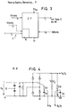
- FIG. 5 shows an exemplary embodiment of a load circuit 40 according to the invention with a heat exchanger L5 for preheating the filaments of the fluorescent lamp LA1.
- the exemplary embodiment of the invention has a pair of these branches, ie two fluorescent lamps LA1, LA2 at an AC voltage output, which outputs the high-frequency AC voltage U HF between the series-connected power switching transistors V21 and V28.
- the AC voltage generator is supplied with an intermediate circuit voltage U dc from the input circuit 20 shown in FIG. 4. Since the fluorescent lamps have a negative internal resistance during operation, they must be supplied with high voltage peaks during the ignition process (ZÜND) and with appropriate heating energy when heating the Wendein.
- a series resonance circuit L2, C15 leads via a balancing element TR1, which will be explained later, to the discharge path H2, H4 of the fluorescent lamp. Furthermore, a measuring resistor R32 is connected in series with the fluorescent tube, at which a voltage proportional to the lamp current I L1 is tapped and fed to the control and regulating circuit 17.
- An ignition capacitor C17 is connected to ground (ZERO) between coil L2 and capacitor C15.
- a voltage proportional to the heating coil current I W1 is tapped from the latter and fed to the control and regulating circuit 17 as a further system measurement variable. Since the inverter 30 impresses an output voltage and the heat exchanger is essentially parallel to the fluorescent lamp LA1, a voltage is impressed on its secondary windings via the heat exchanger.
- the two secondary windings each supply one of the two heating coils H1, H2 and H3, H4. The sum of the heating coil currents I W1 is thus measured at the primary-side measuring resistor R10.
- the Zener diode V15 which is still connected in series, generates a DC component in the primary winding of L5, which is not transmitted, however, but is missing in the lamp current I L1 and thus supplies the discharge of the lamp with an additional DC component in the large arrangement of approximately 1% of the actual discharge current .
- the "running layers” consist in particular of light / dark zones which occur during dimming and run along the tube at a predetermined speed. A superimposition of low direct current accelerates this running effect in such a way that it no longer has a disturbing effect.
- the inverter 30 is operated at a high frequency f max , so that an alternating voltage occurs at C17 which is not suitable for igniting the lamp LA1.
- the lamp's filaments are heated via L5, whereby, due to the thermistor effect of the filament, the lamp absorbs a high and then a lower heating current.
- the ignition (IGNITION) of the lamp is initiated.
- the series resonance circuit L2, C15 or L3, C16 is strongly damped. On the one hand, this causes a shift in the resonance frequencies f0 and, on the other hand, an immediate drop in the AC voltage applied to the respective lamp. The decrease is detected by the control and regulating circuit 17 via the voltage divider R27, R25 connected in parallel to the lamp. This then initiates the actual operating phase (DIMM) of the lamps.
- DIMM actual operating phase
- the frequency f of the inverter 30 is regulated so that the lamp output corresponds to the predetermined target value, ie the desired brightness level.
- the operating frequency of the alternating voltage generator 30 can also be shifted to values which are in the order of magnitude of the heating frequency or above.
- An output frequency can also be set at a maximum power (MAX) is below the ignition frequency, but still above the resonance frequency of the series resonance circuit L2, C15.
- MAX maximum power
- the operating state of the lamp circuit 14 can vary greatly depending on the lamp used, for example argon or krypton lamps, or depending on the lamp power selected.
- the combination of the capacitor C24 and the diodes V30, V31 results in frequency-dependent damping of the output circuit when the voltage rises. It is particularly important when there are high frequencies and high impedances, e.g. in the case of a missing lamp or when preheating when the filament is already warm
- the wiring of this type helps to limit the excess voltage when the lamp is not lit or is missing if it is undesirable.
- C24 is selected so that the damping remains small enough at the time of ignition.
- Fig. 6 shows the output circuit of Fig. 5 for the two-lamp - two fluorescent lamps on an inverter - operation.
- the symmetry transformer TR1 is also shown here in full. Each winding is traversed by one of the two lamp currents. This takes place in opposite directions, so that when there is a deviation in the current amplitude, a resulting magnetization occurs, which induces a voltage in the inductive element which has a symmetrical effect.
- Such a transformer is advantageous if the two lamps would burn differently bright in the dimmed state due to component tolerances and lamp tolerances as well as different temperature conditions.
- the symmetry element TR1 avoids this in the case of two-lamp luminaires. If several pairs of lamps are operated at an AC voltage output, such a balancing element TR1 must be provided for each pair.
- a signal proportional to the lamp current is obtained from them, which signal can be multiplied by the aforementioned lamp voltage signal in the control and regulating circuit 17 I L1 is set in relation to the inverter branch current I max and from this the relative phase of both currents is used to detect the operating state.
- Detection of an impermissible capacitive operating behavior is answered by the control circuit 17 by increasing the operating frequency f of the inverter 30, with which the load circuit 40 is again operated inductively.
- the above-mentioned capacitive mode of operation mainly occurs with a low supply voltage. With the branch current detection, destruction of components can be safely avoided.
- the digital interface 10 shows the transmitting and receiving device 10 and the coupling filter connected upstream of it, with which the bus coupling to the control line 12 takes place.
- the digital interface 10 is given the setpoints for minimum, maximum and emergency lighting brightness (U NOT , U MIN , U MAX ).
- a digital input DAT is provided, via which both the control signals arrive from a central control device to the decentralized ECG and the error signals are transmitted from the decentralized ECG to the central control device.
- the serial interface enables remote control of the electronic ballast by means of a digital command signal or command word.
- An 8 bit data word is provided as such a digital signal.
- FIG. 8c An advantageous further development of this circuit is shown in FIG. 8c.
- the circuit is protected against polarity reversal by using a secondary winding with center tap.
- Optical coupling can also be used, but this has an increased power consumption.
- control signals 255 (corresponding to 8 bit) brightness values are provided as control signals.
- the control signal "OFF”, represented by the binary word “zero” is also possible. With the aforementioned signal OFF, the entire ECG switches to an energy-saving shutdown mode (SLEEP) immediately or after a short period of time. In him the is. In this way it is ensured that at any time of the actual lamp power is P or E brightness proportional signal is available, which can be preset to a precise brightness control as the feedback.
- SLEEP energy-saving shutdown mode
- FIG. 7 shows the inverter 30 in more detail with its output power transistors V28, V21. Between them, the high-frequency alternating voltage U HF is output to the load circuit 40 explained above.
- the two power transistors are controlled via a control circuit 31, which receives its control signals from the control and regulating circuit 17. Possibly. asymmetrical switch-off / switch-on delays for the respective transistors come into consideration, so that a common conduction of both transistors V21, V28 can be avoided in principle.
- the upper transistor is supplied via a bootstrap circuit (not shown), the lower transistor and the system control 10, 17, 31 receive their drive voltage via a series resistor and a smoothing capacitor C5 from the intermediate circuit voltage U0.
- the current that can be supplied to the smoothing capacitor C5 through the series resistor or a current source I q is sufficient to supply the IC31 and the control and regulating circuit 17 in the switched-off mode (SLEEP).
- the load circuit 40 of the inverter 30 is in an impermissible capacitive range. It represents a danger for the controlling inverter.
- a phase angle analysis can also be used in which the load current Measuring current consumption of the entire ballast minimal.
- the inverter 30 and the control circuit 31 are shut down and, if necessary, after a slight further time delay, the essential assemblies of the control and regulating circuit 17. Only the receiving circuit of the transmitting and receiving device 10 and the monitoring circuit for the detection of an emergency operation (EMERGENCY) remain activated. The total circuit power thus drops below 1 W.
- control and regulating circuit 17 immediately carries out the switch-on sequence, which, with preheating and ignition process (IGNITION), transfers to steady-state operation and is used for one immediate setting of the desired brightness value (DIMM) is ensured.
- IGNITION preheating and ignition process
- control and regulating circuit 17 is also responsible for extracting the information from all of the aforementioned process variables which are important for monitoring and controlling the electronic ballast.
- the various operating states of the fluorescent tube can also be distinguished by the measured variables.
- the measured process variables and those used for checking are summarized below: Supply voltage U ac , U N , Undervoltage / overvoltage U Nmin , U Nmax , Battery voltage U B , DC link voltage U0, U dc , Lamp current / operating current I L1 , I L2 , Lamp voltage U L1 , U L2 , Output voltage U HF , Output current I HF , Spiral current I W1 , I W2 , AC generator branch current I Chap .
- the control and regulating circuit 17 switches off all functions when the voltage becomes too high, and can only function again when the voltage has been switched off and on again.
- An emergency mode switchover to a predeterminable emergency lighting brightness takes place, for example, when a DC voltage U N is detected by the control circuit 17 via the usual AC voltage input of the switch-on circuit 20 and via the sensors R21, C25 (FIG. 4).
- a counter logic is used for this purpose, which initiates emergency operation if there is no exceeding or falling below a predetermined threshold value. This can take place after a predetermined dead time that bridges individual, possibly missing, half-waves.
- an emergency voltage supply U B which is obtained from batteries or a generator, is placed on the mains voltage line.
- the ECGs recognize this automatically.
- the brightness of the fluorescent lamps is no longer specified by the digitally specified brightness value DIMM, but by a trim value that can be specified locally on the device and can be specified via the input U NOT .
- the ECG is in switch-off mode (SLEEP) when this emergency operation occurs, ie the lamp and inverter are switched off, it will first carry out the normal ignition process (IGNIT) in order to subsequently switch to the emergency actuation brightness.
- the electronic ballast When the end of the emergency operating state is recognized, the electronic ballast returns to the previous state; this can be the OFF state if the electronic ballast was previously there. However, this can also be the original brightness value (DIMM), if this was available before requesting emergency operation.
- DIMM original brightness value
- the detection of the filament current detects whether either a lamp is not inserted or one of the two filaments is broken.
- the inverter 30 is operated at its maximum frequency f max , which on the one hand results in a heating current still flowing when the defective lamp has been replaced and on the other hand reduces the voltage on the defective lamp to the smallest possible extent .
- f max maximum frequency
- the inductive part of the series resonance circuit in the output becomes so high at the high frequency f max compared to the capacitive resistance of the ignition capacitor C17 that the voltage at the output is limited to harmless values and there is no danger for the maintenance personnel.
- the ignition process (IGNITION) is initiated without waiting for the preheating time to elapse.
- the internal sequence control in the control and regulating circuit 17 also limits the number of start attempts to two and sets (sends) whenever there is an error, e.g. B. the lamp is missing if a filament break or a gas defect is present, an error signal via the transmitting and receiving device 10 on the bidirectional bus 12. This also applies in emergency mode, since emergency mode cannot be maintained if the lamp is defective.
- an error e.g. B. the lamp is missing if a filament break or a gas defect is present
- Wiring errors which lead to a short circuit in the discharge path of the lamp, can be detected on the basis of the process signals when the lamp voltages are monitored for a predetermined minimum value. If the value falls below this specified value, as in the case of mains overvoltage monitoring, the entire ECG is switched off.
- the unwillingness to ignite the lamp e.g. B. by gas defect, is recognized by the control and regulating circuit 17. If the lamp cannot be ignited within a predetermined ignition target time, i. H. if the voltage across the ignition capacitor C17 does not fall within this time period, the lock mentioned intervenes.
- a repeat time can also be waited for after which a new attempt to start and start is made. If no ignition success is achieved here either, the control and regulating circuit 17 reacts as in the case of a broken heating coil and sets the frequency of the inverter 30 to the maximum value f max .
- control and regulating circuit 17 recognizes by an increase in the lamp voltage or by a change in the heating coil current, an attempt is made to fire again after a new lamp has been inserted.
- the following is explained for the brightness control of the fluorescent lamps.
- a real brightness control is used, since this guarantees the same lamp outputs regardless of the lamp type - with essentially the same lamp efficiency.
- the measured values determining the actual value, lamp current and lamp voltage are multiplied and compared in analog or digital form with the setpoints predetermined by remote control via the transmitting and receiving device 10.
- the comparison result controls the frequency f of the alternating voltage generator 30 directly or via a controller. If a more precise gradation of brightness is desired, a logarithmic setpoint adjustment can take place. Exponential actual value weighting can be carried out in the same way. In addition to the independence of the lamp type, compensation is also achieved for lamp age, the existing operating temperature and also the possibly fluctuating mains voltage U N.
- FIG. 9 shows a brightness-time diagram in which the brightness of the lamp controlled by the electronic ballast according to FIG. 1 is varied as a function of time.
- maximum brightness is provided, followed by a switch-off cycle specified via the bus line 12 and the digital interface 10.
- the brightness is acc. a predetermined slope reduced to zero, then the inverter 30, its driver circuit 31 and essential parts of the control IC 17 turn off to save electricity.
- a subsequent emergency lighting condition leads - despite switched off system - for a controlled ignition and a build-up of the brightness of the lamp to the preset emergency lighting brightness (NOT).
- NOT preset emergency lighting brightness
- This can be changed for each decentralized ECG via the setpoint specification U NOT .
- the maximum and minimum brightness value (MIN, MAX) shown in FIG. 9 can be set or adjusted via a corresponding setpoint value.
- a program-controlled "soft start” is shown schematically in FIG. 10 as a brightness-time diagram.
- the ECG 60 is initially in the switched-off state (OFF).
- the "Softstart” command now leads either to an automatic, slope-controlled increase in lamp brightness - after it has been ignited - or to a program-controlled incremental increase in lamp brightness levels. In the latter case, the central starter device 50 sends incrementally increasing brightness values in certain time segments.
- the decentralized ECGs follow the requirements almost without delay. This enables a rate of change-controlled (regulated) rise and fall of the decentralized light sources.
Abstract
Description
Die Erfindung betrifft allgemein ein elektronisches Vorschaltgerät (EVG) für Leuchtstofflampen. Insbesondere betrifft sie Schaltungsanordnungen innerhalb des elektronischen Vorschaltgerätes sowie ein Verfahren zur Steuerung der Helligkeit und des Betriebsverhaltens von Leuchtstofflampen.The invention relates generally to an electronic ballast (EVG) for fluorescent lamps. In particular, it relates to circuit arrangements within the electronic ballast and a method for controlling the brightness and the operating behavior of fluorescent lamps.
Elektronische Vorschaltgeräte moderner Bauweise dienen der Ansteuerung von Leuchtstofflampen. Dabei werden die Leuchtstofflampen zum einen schonender betrieben und zum anderen kann der Wirkungsgrad derartiger Lampentypen heraufgesetzt werden. Ein elektronisches Vorschaltgerät weist dabei regelmäßig die im Oberbegriff des Anspruchs 1 angegebenen Merkmale auf.Modern electronic ballasts are used to control fluorescent lamps. The fluorescent lamps are operated more gently on the one hand and on the other hand the efficiency of such lamp types can be increased. An electronic ballast regularly has the features specified in the preamble of
Über einen Netzeingangsfilter wird eine Versorgungsspannung die eine Gleich- oder Wechselspannung sein kann, einem Gleichrichter und einem Zwischenkreiskondensator zugeführt. Soweit das Gerät ausschließlich mit Gleichspannung betrieben wird, kann letzterer Gleichrichter entfallen. Auf dem Zwischenkreiskondensator wird eine hohe Zwischenkreisspannung U₀ gebildet, die bei üblicher Netzspannungsversorgung von 220 V in der Großenordnung von ca. 300 V liegt. An den Zwischenkreis schließt sich ein Wechselspannungsgenerator an, dieser wird von einem Halbbrücken- oder Vollbrückenwechselrichter gebildet. Er gibt eine frequenzvariable Ausgangsspannung an einen Ausgangs-Lastkreis ab, der, sofern keine Halbbrückenschaltung mit künstlichem Spannungsmittelabgriff vorgesehen ist, einen Serienresonanzkreis aufweist. In Reihe zu dem Serienresonanzkreis liegt die Entladungsstrecke der zu steuernden Gasentladungslampe oder Leuchtstofflampe.A supply voltage, which can be a direct or alternating voltage, is fed to a rectifier and an intermediate circuit capacitor via a mains input filter. If the device is operated exclusively with DC voltage, the latter rectifier can be omitted. A high intermediate circuit voltage U₀ is formed on the intermediate circuit capacitor, which is of the order of magnitude of approximately 300 V with a conventional mains voltage supply of 220 V. An AC voltage generator is connected to the DC link, which is formed by a half-bridge or full-bridge inverter. It outputs a frequency-variable output voltage to an output load circuit which, unless a half-bridge circuit with an artificial voltage means tap is provided, has a series resonance circuit. The discharge path of the gas discharge lamp or fluorescent lamp to be controlled is in series with the series resonant circuit.
Die Ausgangsfrequenz des Wechselrichters beträgt in etwa 10 kHz - 50 kHz.The output frequency of the inverter is approximately 10 kHz - 50 kHz.
Bei den genannten Frequenzen wird der Wirkungsgrad der angeschlossenen Leuchtstofflampen gegenüber einem Betrieb an dem 50 Hz-Versorgungsnetz erhöht. Eine erhöhte Lichtausbeute wird bei gleicher elektrischer Leistungsaufnahme erzielt. Weiterhin kann aufgrund der hohen Frequenz die wechselrichter-ausgangsseitige Induktivität des Serienresonanzkreises kleingehalten werden. Schließlich erlaubt die variable Frequenzsteuerung eine Helligkeitsregelung der - am normalen Netz nur schwer helligkeitsregelbaren (dimmbaren) - Leuchtstofflampe. Hinzu kommt schließlich, daß über die Frequenzsteuerung auch eine Zündung der Leuchtstofflampe vorbereitet und initiiert werden kann.
Zu dem vorgenannten Zündvorgang gehört zur Schonung der Leuchtstofflampen auch ein sog. Warmstart, bei dem die Heizwendeln der Leuchtstofflampe vorgeheizt werden, bevor die Lampe aufgrund von Resonanzerscheinungen mit einer hohen Zündspannung beaufschlagt wird, die zur Zündung und damit zum Betrieb der Gasentladungslampe führt. Die Variation der Frequenz, welche die Zündung kontrolliert, erlaubt auch im Betrieb der Gasentladungslampe durch Frequenzverschiebung eine nahezu stufenlose Helligkeitsregelung in weiten Grenzen. Eine solche stufenlose und kontinuierliche Steuerung der Helligkeit erfordert aufgrund des negativen Innenwiderstandes der in Betrieb befindlichen Leuchtstofflampe besondere Maßnahmen.At the frequencies mentioned, the efficiency of the connected fluorescent lamps is increased compared to operation on the 50 Hz supply network. An increased luminous efficiency is achieved with the same electrical power consumption. Furthermore, due to the high frequency, the inductance of the series resonant circuit on the output side of the inverter can be kept small. Finally, the variable frequency control enables brightness control of the fluorescent lamp, which is difficult to regulate (dimmable) in the normal network. Finally, there is that An ignition of the fluorescent lamp can also be prepared and initiated via the frequency control.
To protect the fluorescent lamps, the aforementioned ignition process also includes a so-called warm start, in which the heating filaments of the fluorescent lamp are preheated before the lamp is subjected to a high ignition voltage due to resonance phenomena, which leads to ignition and thus to the operation of the gas discharge lamp. The variation of the frequency that controls the ignition allows an almost infinitely variable brightness control within wide limits even during operation of the gas discharge lamp by frequency shift. Such a continuous and continuous control of the brightness requires special measures due to the negative internal resistance of the fluorescent lamp in operation.
Wesentlicher Gesichtspunkt für die Entwicklung eines modernen EVG bildet daher zum einen eine möglichst vielseitige Steuerungsmöglichkeit insbes. eine Helligkeitsregelung. Dies im Hinblick auf das Betriebsverhalten sowie die Helligkeitsregelung der an einem jeweiligen EVG angeschlossenen Leuchtstofflampen.An essential aspect for the development of a modern electronic ballast is therefore a control option that is as versatile as possible, in particular a brightness control. This with regard to the operating behavior and the brightness control of the fluorescent lamps connected to a respective electronic ballast.
Neben einer vielseitigen Steuerung und Regelung ist es ein anderes Anliegen moderner EVGs eine komfortable Handhabung und Bedienung vieler dezentral angeordneter Lichtquellen zu gewährleisten. Dies insbesondere im Hinblick auf Großprojekte, bei denen weitläufige Beleuchtungssysteme mit einer großen Anzahl von Lichtquellen zu installieren sind.In addition to versatile control and regulation, it is another concern of modern ECGs to ensure comfortable handling and operation of many decentralized light sources. This is particularly the case with regard to large-scale projects in which extensive lighting systems with a large number of light sources have to be installed.
Schließlich ist es ein wesentlicher Zweck der Erfindung, erhöhte Sicherheit für die angeschlossenen Leuchtstofflampen sowie eine verbesserte Überwachungsmöglichkeit dieser zu schaffen. Sicherheit nicht zuletzt auch für das Betriebspersonal, was ausgefallene Lampen zu wechseln hat und hierbei darauf angewiesen ist, daß die beim Lampenwechsel an dem Steckfassungen und im Gerät entstehenden Spannungen für sie ungefährlich sind. Dies aus dem Grunde, da bei weitläufigen Beleuchtungssystemen die einzelnen Lampen nicht individuell abschaltbar sind, sodaß ein Lampenwechsel im Betrieb notwendig wird.Finally, it is an essential purpose of the invention to provide increased security for the connected fluorescent lamps and an improved possibility of monitoring them. Last but not least, also for the operating personnel, which has to change failed lamps and is dependent on the fact that the voltages that arise at the lamp sockets and in the device when changing lamps are harmless for them. This is because, in the case of extensive lighting systems, the individual lamps cannot be switched off individually, so that a lamp change is necessary during operation.
Des weiteren sollen vermeidbare Leistungsverluste bei der Ansteuerung der Gasentladungslampen tatsächlich vermieden werden.Furthermore, avoidable losses in power when driving the gas discharge lamps should actually be avoided.
Die zuvor genannten technischen Probleme werden erfindungsgemäß durch die in den unabhängigen Ansprüchen angegebenen kennzeichnenden Merkmale gelöst.According to the invention, the aforementioned technical problems are solved by the characterizing features specified in the independent claims.
Das erfindungsgemäße Verfahren sowie die erfindungsgemäße Schaltungsanordnung ermöglichen es, die Steuerfunktionen und die Helligkeitsregelung besonders genau und komfortabel zu handhaben. Hierzu ist eine Steuer- und Regeleinrichtung vorgesehen, die alle wesentlichen Steuer-, Regel- und Überwachungsfunktionen für ein dezentrales EVG übernimmt. Über eine der Steuer- und Regeleinrichtung zugeordnete Schnittstelle können Steuerbefehle und Helligkeitsbefehle zugeführt werden, die von der Steuer- und Regeleinrichtung, abhängig von den derzeit gültigen Prozeßgrößen (Meßgrößen) des jeweiligen dezentralen EVG, ausgeführt wird. Neben einem helligkeitsgeregelten Dimmbetrieb (DIMM) ist erfindungsgemäß auch ein Sleep-Betrieb vorgesehen, bei dem das gesamte EVG stillgelegt wird, wenn längere Zeit keine Helligkeit gewünscht wird. in diesem Zustand nimmt das EVG nur eine minimale Leistung auf und vermeidbare Verluste werden tatsächlich vermieden.The method according to the invention and the circuit arrangement according to the invention make it possible to handle the control functions and the brightness control particularly precisely and comfortably. For this purpose, a control and regulating device is provided, which takes over all essential control, regulating and monitoring functions for a decentralized ECG. Control commands and brightness commands can be supplied via an interface assigned to the control and regulating device and are executed by the control and regulating device depending on the currently valid process variables (measured variables) of the respective decentralized ECG. In addition to a brightness-controlled dimming operation (DIMM), sleep operation is also provided according to the invention, in which the entire electronic ballast is shut down if no brightness is desired for a long time. in this state, the electronic ballast consumes minimal power and avoidable losses are actually avoided.
Die Schnittstelle der Steuer- und Regeleinrichtung dient als Empfangs-, vorzugsweise auch als Sendeeinrichtung.The interface of the control and regulating device serves as a receiving device, preferably also as a transmitting device.
Vorteilhaft werden in einem jeweiligen dezentralen EVG ein Paar von Leuchtstofflampen an einem Wechselspannungsgenerator betrieben. Dies entspricht einem sog. zweiflammigen EVG.A pair of fluorescent lamps are advantageously operated on an AC voltage generator in a respective decentralized ECG. This corresponds to a so-called two-lamp electronic ballast.
Neben der komfortablen Helligkeitsregelung erlaubt die Steuer- und Regeleinrichtung zielgerichtet eine Erhöhung der Lebensdauer der Leuchtstofflampen und eine Gewährung von Sicherheitsinteressen. Mittels der vorgenannten Steuer- und Regeleinrichtung kann das Betriebsverhaltung und der jeweilige Betriebszustand der von einem EVG versorgten Leuchtstofflampen genauestens gesteuert und überwacht werden. So werden Warmstart-, Zünd-, Dimm- und Abschaltvorgang (ZÜND,DIMM,AUS,EIN) mit hoher Präzision und lampenschonend aneinandergereiht. Unzulässige Betriebsbedingungen werden vermieden, vor einer jeweiligen Zündung wird für eine ausreichende Vorwärmung der Heizwendeln gesorgt.In addition to the convenient brightness control, the control and regulation device allows an increased lifespan of the fluorescent lamps and the granting of safety interests. Using the aforementioned control and regulating device, the operating behavior and the respective operating state of the fluorescent lamps supplied by an electronic ballast can be precisely controlled and monitored. In this way, warm start, ignition, dimming and switch-off processes (IGNITION, DIMM, OFF, ON) are strung together with high precision and gentle on the lamp. Inadmissible operating conditions are avoided, and sufficient heating of the heating coils is ensured before each ignition.
Neben dem regelmäßigen Dimmbetrieb, in welchem die Helligkeit der Leuchtstofflampen zwischen einem Minimalwert (MIN) und einem Maximalwert (MAX) beliebig variierbar ist (DIMM) ist auch ein Notbetrieb (NOT) möglich, bei dem die Lampe einen Notbeleuchtungs-Lichtpegel einnimmt. Dieser ist dezentral am jeweiligen Gerät vorgebbar. Bei bestimmten Gefahrenbedingungen wird er automatisch aktiviert.In addition to regular dimming, in which the brightness of the fluorescent lamps can be varied as required (DIMM) between a minimum value (MIN) and a maximum value (MAX), emergency operation (EMERGENCY) is also possible, in which the lamp assumes an emergency lighting light level. This can be specified locally on the respective device. It is automatically activated under certain hazard conditions.
Vorteilhaft ist die Sende- und Empfangseinrichtung über eine bidirektionale Busleitung mit einem zentralen Steuergerät verbunden. Ein solches erlaubt es, von einer zentralen Stelle aus eine Vielzahl von dezentral angeordneten EVGs fernzusteuern. Neben der Fernsteuerung bietet das Steuergerät auch eine Betriebszustandsinformation. Es werden im Beleuchtungssystem aufgetretene Fehler aufgrund von Fehlermeldungen erkannt und angezeigt, die von den dezentralen EVGs über die bidirektionale Busleitung an das zentrale Steuergerät gesandt worden sind. Wartungsarbeiten werden hierdurch vereinfacht und beschleunigt. Vielfältige Überwachungsfunktionen werden bereits dezentral vorgesehen, so die Über- und Unterspannungsüberwachung. Durch sie wird die Lebensdauer der Leuchtstofflampen spürbar erhöht.The transmitting and receiving device is advantageously connected to a central control device via a bidirectional bus line. This allows remote control of a large number of decentralized ECGs from a central location. In addition to remote control, the control unit also provides operating status information. Errors that occur in the lighting system are recognized and displayed on the basis of error messages sent by the decentralized ECGs via the bidirectional bus line have been sent to the central control unit. This simplifies and speeds up maintenance work. A variety of monitoring functions are already provided locally, such as overvoltage and undervoltage monitoring. It noticeably increases the lifespan of the fluorescent lamps.
Die über die Busleitung gesteuerte Helligkeitsregelung der dezentralen EVGs geschieht über serielle digitale Steuerworte, die Steuerbefehle oder Helligkeits-Dateninformationen darstellen. Besonders vorteilhaft ist die Organisation in Funktionsgruppen, in welchen eine Mehrzahl von EVGs, die beispielsweise in einem Raum angeordnet sind, gleichzeitig und mit einem einzelnen Befehl ansteuerbar sind.The brightness control of the decentralized ECGs, which is controlled via the bus line, takes place via serial digital control words that represent control commands or brightness data information. Organization in functional groups is particularly advantageous, in which a plurality of electronic ballasts, which are arranged, for example, in a room, can be controlled simultaneously and with a single command.
Die Ankopplung der Sende- und Empfangseinrichtungen an die Busleitung wird vorteilhaft durch ein Differenzierglied bewirkt. Sie gewährt eine starke Dämpfung der 50 Hz-Netzfrequenzen und arbeitet mit sehr geringen Eingangsströmen. Die Dämpfung der Netzfrequenzen geht soweit, daß auch ein Verpolungsschutz gewährt wird, das Anlegen von 220 V an der Busleitung bleibt ohne Schadensfolge.The coupling of the transmitting and receiving devices to the bus line is advantageously effected by a differentiator. It provides a strong attenuation of the 50 Hz network frequencies and works with very low input currents. The attenuation of the network frequencies goes so far that reverse polarity protection is also provided; the application of 220 V to the bus line remains without damage.
Wenn die Leuchtstofflampen nach einem Zündvorgang in den gedimmten Betrieb gesteuert werden, kann es dazu kommen, daß kurzzeitige Lichtpulse auftreten. Sie haben ihre Ursache in der im Ausgangskreis gespeicherten Energie des Zündvorganges, der sich anschließend unerwünscht als Lichtpuls im gedimmten Betrieb äußert. Hier kann durch Verlängern der - eigentlich lebensdauerverkürzenden - Glimmphase zwischen Zünd- und stationärem Betrieb Abhilfe geschaffen werden. Eine tatsächliche Lebensdauerverkürzung wird aber dadurch vermieden, daß der Glimmbereich nur bei geringen Helligkeitswerten verlängert wird. Je größer die Helligkeit, desto kürzer demnach die Glimmphase und desto schneller der Übergang vom Zündbetrieb zum Normalbetrieb.If the fluorescent lamps are switched to dimmed operation after an ignition process, there may be short-term light pulses. They have their cause in the energy of the ignition process stored in the output circuit, which then expresses itself undesirably as a light pulse in dimmed operation. This can be remedied by extending the glow phase - which actually shortens the lifespan - between ignition and stationary operation. However, an actual shortening of the service life is avoided by the fact that the glow area is only extended at low brightness values. The greater the brightness, the shorter the glow phase and the faster the transition from ignition to normal operation.
Werden erfindungsgemäß der Steuer- und Regeleinrichtung eine Mehrzahl m von Meßgrößen aus dem EVG zugeführt, so können hieraus eine Vielzahl von Betriebszuständen und ggf. Gefahrenzustände erkannt und vermieden werden. Weiterhin wird eine echte Leistungsregelung möglich, die lampentypunabhängig (beispielsweise Argon-Lampen oder Krypton-Lampen) arbeitet. Vorteilhaft wird die Lampenhelligkeitsregelung durch eine Frequenzmodulation oder durch eine Kombination von Frequenzmodulation und Tastverhältnisänderung erzielt.If, according to the invention, the control and regulating device is supplied with a plurality m of measured variables from the electronic ballast, a large number of operating states and possibly dangerous states can be identified and avoided therefrom. Furthermore, real power control is possible, which works regardless of the lamp type (for example, argon lamps or krypton lamps). The lamp brightness control is advantageously achieved by frequency modulation or by a combination of frequency modulation and duty cycle change.
Zum Aspekt der Überwachung zählt auch die Kontrolle der Heizwendelströme der Leuchtstofflampen. Sie erlauben eine präzise Ermittlung, ob bestimmte Lampen defekt sind oder ggf. gar nicht eingebaut wurden.Monitoring also includes checking the heating coil currents of the fluorescent lamps. They allow a precise determination of whether certain lamps are defective or possibly not installed at all.
Die bei starken Dimmbetrieb auftretenden "laufenden Schichten" werden vorteilhaft dann vermieden, wenn dem hochfrequenten Lampenwechselstrom eine geringe Gleichkomponente überlagert wird.The "running layers" that occur during strong dimming operation are advantageously avoided if a low DC component is superimposed on the high-frequency lamp alternating current.
Werden pro EVG ein Paar von Leuchtstofflampen eingesetzt, die von einem gemeinsamen Wechselspannungsgenerator gespeist werden, so bewirkt das erfindungsgemäße induktive Symmetrierelement einen symmetrischen Betrieb beider Leuchtstofflampen. Eine spannungsgesteuerte Wendelbeheizung ermöglichen die lampenindividuellen Heizübertrager, welche mit ihrer Primärwicklung am Wechselspannungs-Ausgangskreis angeschlossen sind. Über eine Primärstromerfassung kann die Steuer- und Regeleinrichtung jederzeit Rückschlüsse auf die Heizwendelbeschaffenheit ziehen und so bereits beschädigte Leuchtstofflampen oder in Kürze ausfallende Leuchtstofflampen identifizieren.If a pair of fluorescent lamps are used per ECG, which are fed by a common AC voltage generator, the inductive balancing element according to the invention effects symmetrical operation of both fluorescent lamps. The lamp-specific heat exchangers, which are connected with their primary winding to the AC output circuit, enable voltage-controlled coil heating. The control and regulating device can draw conclusions about the nature of the heating coil at any time via primary current detection and thus identify already damaged fluorescent lamps or fluorescent lamps that will soon fail.
Weitere vorteilhafte Aspekte und Ausführungsformen des erfindungsgemäßen EVG und des erfindungsgemäßen Arbeitsverfahrens sind in den Unteransprüchen näher ausgeführt. Gestützt auf die Zeichnung werden nachfolgend Ausführungsbeispiele der Erfindung näher erläutert. Es zeigen
- Fig. 1 ein Blockschaltbild eines erfindungsgemäßen EVG,
- Fig. 2 ein Blockschaltbild eines erfindungsgemäßen Systemgedankens, bei dem mehrere dezentrale EVGs mit einem zentralen Steuergerät über eine Busleitung 12 verbunden sind,
- Fig. 3 ein Blockschaltbild eines Ausführungsbeispiels der erfindungsgemäßen Steuer- und Regeleinrichtung
als integrierte Schaltung 17, - Fig. 4 ein Prinzipschaltbild eines Eingangskreises 20 mit zwei Meßwerterfassungen,
- Fig. 5 ein Ausführungsbeispiel der transformatorgekoppelten Wendelbeheizung einer Leuchtstofflampe mit drei Meßfühlern,
- Fig. 6 ein Ausführungsbeispiel eines erfindungsgemäßen Ausgangskreises 40 mit Symmetrierelement TR1 für zwei Leuchtstofflampen,
- Fig. 7 ein Prinzipschaltbild des Wechselspannungsgenerators mit ihn ansteuernder Treiberschaltung 31,
- Fig. 8a-c jeweils ein Blockschaltbild der Sende-
und Empfangseinrichtung 10 mit verschieden ausgestalteten Koppelschaltungen zur Busleitung 12, - Fig. 9 ein Helligkeits-Zeitdiagramm zur Erläuterung des Abschalt- und des Notbeleuchtungsbetriebes,
- Fig. 10 ein Helligkeits-Zeitdiagramm zur Erläuterung der Softstart- bzw. Softstop-Funktion bei einer Systemkonfiguration gem. Fig. 2.
- 1 is a block diagram of an electronic ballast according to the invention,
- 2 shows a block diagram of a system concept according to the invention, in which several decentralized electronic ballasts are connected to a central control device via a
bus line 12, - 3 shows a block diagram of an exemplary embodiment of the control and regulating device according to the invention as an
integrated circuit 17, - 4 shows a basic circuit diagram of an
input circuit 20 with two measured value recordings, - 5 shows an exemplary embodiment of the transformer-coupled filament heating of a fluorescent lamp with three sensors,
- 6 shows an exemplary embodiment of an
output circuit 40 according to the invention with a balancing element TR1 for two fluorescent lamps, - 7 shows a basic circuit diagram of the AC voltage generator with
driver circuit 31 driving it, - 8a-c each show a block diagram of the transmitting and receiving
device 10 with differently configured coupling circuits for thebus line 12, - 9 is a brightness-time diagram to explain the shutdown and emergency lighting operation,
- 10 is a brightness-time diagram to explain the soft start or soft stop function in a system configuration according to FIG. Fig. 2.
Fig. 1 zeigt zunächst ein Blockschaltbild eines Ausführungsbeispiels eines erfindungsgemäßen EVGs. Die Netzspannung UN wird - ggf. über einen Schalter S1 - dem Eingangsschaltkreis 20 (Gleichrichterschaltkreis) zugeführt. Dieser erzeugt die Zwischenkreisspannung U₀,Udc, die dem Wechselspannungsgenerator 30 (Wechselrichter) zugeführt wird. Der Wechselspannungsgenerator 30 gibt seine hochfrequente Ausgangsspannung UHF an einen Ausgangs-Lastkreis 40 ab, der eine oder mehrere Leuchtstofflampen LA1,LA2 enthält. Sowohl dem Wechselspannungsgenerator 30 als auch dem Lastkreis 40 sind eine Mehrzahl von System-Meßwerten (Prozeßgrößen) entnehmbar. Gemeinsam werden die Meßwerte einer Steuer- und Regelschaltung 17 zugeführt, die ihrerseits die digitalen Ansteuersignale für den Wechselrichter 30 erzeugt. Diese werden über eine Treiberschaltung 31 potentialverschoben und den Ausgangs-MOS-FETs des Wechselrichters zugeführt. Der Steuer- und Regeleinrichtung 17 ist außerdem eine Sende- und Empfangseinrichtung 10 zugeordnet, die über eine Busleitung 12 mit anderen EVGs und/oder mit einem zentralen Steuergerät 50 verbunden ist. 1 shows a block diagram of an exemplary embodiment of an electronic ballast according to the invention. The mains voltage U N is supplied to the input circuit 20 (rectifier circuit), possibly via a switch S1. This generates the intermediate circuit voltage U₀, U dc , which is fed to the AC voltage generator 30 (inverter). The
Letzteres wird von Fig. 2 gezeigt. Dort sind eine Mehrzahl von EVGs 60-1,60-2,60-3,...,60-i an einer gemeinsamen Busleitung 12 angeschlossen. Alle EVGs sind über diese Busleitung mit dem zentralen Steuergerät 50 verbunden, dem eine Anzeigeeinheit 51 zugeordnet ist. Über die Busleitung 12 wird es nun möglich, einzelne oder mehrere der genannten EVGs anzusteuern und ihnen Befehle zu übertragen, wie Ausschalten, Einschalten, Zünden o. ä. Auch können Helligkeitswerte voreingestellt werden und im Gegenzug Fehlerinformationen von den einzelnen Geräten abgefragt werden. So ist das Steuergerät 50 jederzeit über den Gesamt-Systemzustand informiert, wodurch ein hohes Maß an Betriebssicherheit gewährt werden kann und eine beschleunigte Wartung der dezentralen EVGs, bzw. für deren Leuchtstofflampen, möglich wird.The latter is shown in Fig. 2 . There, a plurality of electronic ballasts 60-1, 60-2, 60-3, ..., 60-i are connected to a
Die in Fig. 1 gezeigten Funktionsblöcke 20,30,40,10,17 werden anhand der folgenden Figuren nun näher erläutert.The functional blocks 20, 30, 40, 10, 17 shown in FIG. 1 will now be explained in more detail with reference to the following figures.
Fig. 3 zeigt hierzu die Steuer- und Regeleinrichtung 17 als integrierte Schaltung. Ihr werden die Vielzahl von Meßwerten m, welche den Prozeßsignalen der Fig. 1 entsprechen, zugeführt. Sie gibt zwei digitale Ansteuersignale für die Endstufen-Transistoren des Wechselrichters 30 ab, die über eine Treiberschaltung 31 noch verstärkt und potentialverschoben werden. 3 shows the control and regulating
Neben den m Meßwerten werden der Steuer- und Regeleinrichtung 17 auch n Sollwerte zugeführt. Diese beeinflussen das vorgebbare Steuer- und Regelverhalten. Weiterhin ist als Teil der Steuer- und Regelschaltung 17 oder separat eine Sende- und Empfangseinrichtung 10 vorgesehen, die direkt oder mittels eines Koppelschaltkreises mit der Busleitung 12 verbunden ist. Sie bildet die serielle Schnittstelle, die es der Steuer- und Regeleinrichtung ermöglicht, Fehler- und Betriebszustandsinformationen dem zentralen Steuergerät 50 zu übermitteln.In addition to the m measured values, the control and regulating
Die zuvor genannten n Sollwerte können auch dieser Sende- und Empfangseinrichtung 10 zugeführt werden, die sie nach entsprechender Aufbereitung an die Steuer- und Regelschaltung 17 weitergibt. Sollwerte können beispielsweise sein der Notbeleuchtungspegel (NOT), der minimale Helligkeitspegel (MIN) und der maximale Helligkeitspegel (MAX), innerhalb letzterer beider kann sich der vorgebbare Helligkeitspegel (DIMM) im Betrieb bewegen.The aforementioned n setpoints can also be supplied to this transmitting and receiving
Als Befehls- und Datenworte sowie als Fehlerinformationsworte werden serielle digitale Datenworte verwendet, deren Länge 8 bit ist. Andere Wertlängen sind möglich. Jedem dezentralen EVG wird eine Adresse zugeordnet, die es ermöglicht, einzelne EVGs über die Adresse der Sende- und Empfangseinrichtung 10 anzusprechen und Informationen von ihnen abzufragen oder ihnen Befehle zu erteilen. Die bidirektionelle Arbeitsweise der Busleitung 12 ermöglicht ein problemloses und aufwandsarmes Verkabeln einer Vielzahl von dezentraler EVGs mit einem zentralen Steuergerät (50).Serial digital data words, the length of which are 8 bits, are used as command and data words and as error information words. Other value lengths are possible. An address is assigned to each decentralized ECG, which makes it possible to address individual ECGs via the address of the transmitting and receiving
Fig. 4 zeigt ein Prinzipschaltbild eines Eingangskreises, wie er zur Speisung des Wechselspannungsgenerators 30 aus einem Versorgungsnetz mit der Spannung UN verwendbar ist. Der Eingangskreis besteht aus kapazitiven Eingangsfiltern sowie ggf. aus einer Oberwellendrossel. Die Kondensatoren in Y-Schaltung dienen der Funkentstörung. Ihnen ist ein Überspannungsableiter oder ein VDR parallel geschaltet. Es schließt sich ein Vollwellengleichrichter an, der dann entfallen kann, wenn das Gerät betriebsmäßig mit Gleichspannung betrieben wird. Dem Gleichrichter nachgeschaltet ist ein Zwischenkreiskondensator C4, der sich bei 220 V Netzspannung auf ca. 300 V mit einer Restwelligkeit von ca. 10 % auflädt. FIG. 4 shows a basic circuit diagram of an input circuit as can be used to supply the
Aufgrund eines niedrig zu haltenden Crestfaktors sollte die Zwischenkreisspannung U₀ gut geglättet sein.Due to a crest factor to be kept low, the intermediate circuit voltage U₀ should be smoothed well.
Parallel zum Zwischenkreiskondensator C4 liegt ein Spannungsteiler R18,R28, an dem ein der Zwischenkreis-Spannung proportionales Meßsignal abgreifbar ist. An einem Tiefpaß R21,C25 wird ein der Versorgungsspannung proportionales Signal erfaßt und ebenso, wie das zwischenkreisspannungs-abhängige Meßsignal der Steuer- und Regeleinrichtung 17 zugeführt. Beide Meßsignale dienen der Versorgungsspannungs-Überwachung und damit der Betriebssicherheit des EVG.Parallel to the intermediate circuit capacitor C4 is a voltage divider R18, R28, from which a measurement signal proportional to the intermediate circuit voltage can be tapped. A signal which is proportional to the supply voltage is detected at a low-pass filter R21, C25 and, like the intermediate-circuit voltage-dependent measurement signal, is fed to the control and regulating
Fig. 5 zeigt ein Ausführungsbeispiel eines erfindungsgemäßen Lastkreises 40 mit einem Heizübertrager L5 für die Vorheizung der Wendeln der Leuchtstofflampe LA1. In Fig. 5 ist lediglich einer von einem Paar von Lampenkreisen gezeigt. Das Ausführungsbeispiel der Erfindung weist ein Paar dieser Zweige auf, d. h. zwei Leuchtstofflampen LA1,LA2 an einem Wechselspannungsgenerator-Ausgang, der die hochfrequente Wechselspannung UHF zwischen den in Serie geschalteten Leistungs-Schalttransistoren V21 und V28 abgibt. Der Wechselspannungsgenerator wird aus der in Fig. 4 gezeigten Eingangsschaltung 20 mit einer Zwischenkreisspannung Udc versorgt. Da die Leuchtstofflampen einen negativen Innenwiderstand bei Betrieb besitzen, müssen sie beim Zündvorgang (ZÜND) mit hohen Spannungsspitzen und beim Heizen der Wendein mit entsprechender Heizenergie versorgt werden. Ausgehend von dem Ausgangsanschluß des Wechselrichters 30 führt ein Serienresonanzkreis L2,C15 über ein Symmetrierelement TR1, welches später erläutert wird, auf die Entladungsstrecke H2,H4 der Leuchtstofflampe. Weiterhin ist zu der Leuchtstoffröhre ein Meßwiderstand R32 in Serie geschaltet, an welchem eine dem Lampenstrom IL1 proportionale Spannung abgegriffen und der Steuer- und Regelschaltung 17 zugeführt wird. Zwischen Spule L2 und Kondensator C15 ist ein Zündkondensator C17 gegen Erde (NULL) geschaltet. Mit Hilfe dieser Anordnung kann die Dimmerkennlinie der Entladungslampe vergleichmäßigt werden, da bei steigender Frequenz der Widerstand des Kondensators C15 abnimmt und der Widerstand der Entladungslampe zunimmt. Parallel zu dem Zündkondensator C17 liegt auch die Primärwicklung des Heizübertragers L5 sowie in Serie zu dieser weiterhin eine Zenerdiode V15 und ein Meßwiderstand R10. An letzterem wird eine dem Heizwendelstrom IW1 proportionale Spannung abgegriffen und dem Steuer- und Regelschaltkreis 17 als weitere Systemmeßgröße zugeführt. Da der Wechselrichter 30 eine Ausgangsspannung einprägt und der Heizübertrager im wesentlichen parallel zur Leuchtstofflampe LA1 liegt, wird über den Heizübertrager auf seine Sekundärwicklungen eine Spannung eingeprägt. Die beiden Sekundärwicklungen versorgen je potentialfrei eine der beiden Heizwendeln H1,H2 und H3,H4. An dem primärseitigen Meßwiderstand R10 wird so die Summe der Heizwendelströme IW1 gemessen. 5 shows an exemplary embodiment of a
Die weiterhin in Serie geschaltete Zenerdiode V15 erzeugt in der Primärwicklung von L5 eine Gleichstromkomponente, die aber nicht übertragen wird, sondern im Lampenstrom IL1 fehlt und damit die Entladung der Lampe mit einem zusätzlichen Gleichstromanteil in der Großenanordnung von ca. 1 % des tatsächlichen Entladungsstromes versorgt. Dies verhindert den Effekt der "laufenden Schichten", die bei Dimmung der Lampen auftreten. Die "laufenden Schichten" bestehen aus insbesondere beim Dimmen auftretenden Hell-/Dunkelzonen, die mit einer vorgegebenen Geschwindigkeit längs der Röhre laufen. Ein Überlagern von geringem Gleichstrom beschleunigt diesen Laufeffekt derart, daß er nicht mehr störend wirkt.The Zener diode V15, which is still connected in series, generates a DC component in the primary winding of L5, which is not transmitted, however, but is missing in the lamp current I L1 and thus supplies the discharge of the lamp with an additional DC component in the large arrangement of approximately 1% of the actual discharge current . This prevents the effect of the "running layers" that occur when the lamps are dimmed. The "running layers" consist in particular of light / dark zones which occur during dimming and run along the tube at a predetermined speed. A superimposition of low direct current accelerates this running effect in such a way that it no longer has a disturbing effect.
Zum Heizen wird der Wechselrichter 30 mit einer hohen Frequenz fmax betrieben, so daß an C17 eine Wechselspannung auftritt, die nicht zum Zünden der Lampe LA1 geeignet ist. Über L5 werden in diesem Betriebszustand die Wendein der Lampe beheizt, wobei, bedingt durch den Kaltleitereffekt der Wendein, die Lampe zuerst einen hohen und dann einen geringeren Heizstrom aufnimmt. Nach ca. 750 msec Vorheizzeit wird die Zündung (ZÜND) der Lampe eingeleitet.For heating, the
Beim Zünden der Leuchtstofflampe wird die Frequenz f des Wechselrichters 30 reduziert, sodaß sie näher an die Resonanzfrequenz f des Ausgangs-Serienresonanzkreises L2,C15 herankommt. Dadurch entsteht an C17 eine Spannungsüberhöhung, die in der Größenordnung von ca. 750 V (Spitze) liegt. Hierdurch wird eine funktionsfähige Lampe gezündet.When the fluorescent lamp is ignited, the frequency f of the
Sobald die Lampe LA1 oder LA2 gezündet hat, wird der Serienresonanzkreis L2,C15 oder L3,C16 stark bedämpft. Dies bewirkt einerseits eine Verschiebung der Resonanzfrequenzen f₀ und andererseits ein sofortiges Absinken der an der jeweiligen Lampe liegenden Wechselspannung. Das Absinken wird über den parallel zur Lampe geschalteten Spannungsteiler R27,R25 von dem Steuer- und Regelschaltkreis 17 erkannt. Dieser leitet daraufhin die eigentliche Betriebsphase (DIMM) der Lampen ein.As soon as the lamp LA1 or LA2 has ignited, the series resonance circuit L2, C15 or L3, C16 is strongly damped. On the one hand, this causes a shift in the resonance frequencies f₀ and, on the other hand, an immediate drop in the AC voltage applied to the respective lamp. The decrease is detected by the control and regulating
Zum effektiven Betrieb der Lampe wird die Frequenz f des Wechselrichters 30 so geregelt, daß die Leistung der Lampe dem vorgegebenen Sollwert, d. h. dem gewünschten Helligkeitsniveau, entspricht. Je höher die Frequenz im Betriebszustand wird, desto geringer wird die Lampenhelligkeit. Die Betriebsfrequenz des Wechselspannungsgenerators 30 kann dabei durchaus auch auf Werte verschoben werden, die in der Größenordnung der Heizfrequenz oder darüber liegen. Auch kann bei einer maximalen Leistung (MAX) eine Ausgangsfrequenz eingestellt werden, die unterhalb der Zündfrequenz, aber noch oberhalb der Resonanzfrequenz des Serienresonanzkreises L2,C15 liegt.
Der Betriebszustand des Lampenkreises 14 kann abhängig von der eingesetzten Lampe, beispielsweise Argon-, Krypton-Lampe, oder abhängig von der gewählten Lampenleistung, stark variieren.For effective lamp operation, the frequency f of the
The operating state of the lamp circuit 14 can vary greatly depending on the lamp used, for example argon or krypton lamps, or depending on the lamp power selected.
Die Kombination aus dem Kondensator C24 und den Dioden V30, V31 bewirkt eine frequenzabhängige Bedämpfung des Ausgangskreises bei Spannungsüberhöhung. Sie ist vor allem dann wichtig, wenn hohe Frequenzen und hohe Impedanzen vorkommen, also z.B. bei fehlender Lampe oder beim Vorheizen bei bereits warmer Wendel Die Beschaltung dieser Art hilft, die Spannungsüberhöhung bei nicht gezündeter oder fehlender Lampe dann zu begrenzen, wenn sie unerwünscht ist. C24 ist so gewählt, daß die Bedämpfung zum Zündzeitpunkt klein genug bleibt.The combination of the capacitor C24 and the diodes V30, V31 results in frequency-dependent damping of the output circuit when the voltage rises. It is particularly important when there are high frequencies and high impedances, e.g. in the case of a missing lamp or when preheating when the filament is already warm The wiring of this type helps to limit the excess voltage when the lamp is not lit or is missing if it is undesirable. C24 is selected so that the damping remains small enough at the time of ignition.
Fig. 6 zeigt den Ausgangskreis der Fig. 5 für den zweiflammigen - zwei Leuchtstofflampen an einem Wechselrichter - Betrieb. Hier ist auch der Symmetieübertrager TR1 vollständig eingezeichnet. Jede Wicklung wird von einem der beide Lampenströme durchflossen. Dies geschieht gegensinnig, so daß bei Stromamplituden-Abweichung eine resultierende Magnetisierung entsteht, die in dem induktiven Element eine Spannung induziert, welche symmetrierend wirkt. Ein solcher Übertrager ist vorteilhaft, wenn durch Bauteiltoleranzen und Lampentoleranzen sowie unterschiedlichen Temperaturbedingungen die beiden Lampen im gedimmten Zustand unterschiedlich hell brennen würden. Durch das Symmetrieelement TR1 wird dies bei zweilampigen Leuchten vermieden. Werden mehrere Paare von Lampen an einem Wechselspannungsgenerator-Ausgang betrieben, so ist für jeweils ein Paar ein solches Symmetrierelement TR1 vorzusehen. Fig. 6 shows the output circuit of Fig. 5 for the two-lamp - two fluorescent lamps on an inverter - operation. The symmetry transformer TR1 is also shown here in full. Each winding is traversed by one of the two lamp currents. This takes place in opposite directions, so that when there is a deviation in the current amplitude, a resulting magnetization occurs, which induces a voltage in the inductive element which has a symmetrical effect. Such a transformer is advantageous if the two lamps would burn differently bright in the dimmed state due to component tolerances and lamp tolerances as well as different temperature conditions. The symmetry element TR1 avoids this in the case of two-lamp luminaires. If several pairs of lamps are operated at an AC voltage output, such a balancing element TR1 must be provided for each pair.
Aus Fig. 6 ist weiterhin ersichtlich, daß jeder Leuchtstofflampe ein individueller Serienresonanzkreis vorgeschaltet ist sowie ein individueller Zündkondensator C17,C18 parallelgeschaltet ist. Dies ermöglicht eine relativ unabhängige Zündphase sowie einem Gleichlauf im Dimmbetrieb. Parallel zu den Zündkondensatoren C17,C18 liegt jeweis ein Spannungsteiler R25-R28, die ein der Ausgangs-Wechselspannung proportionales Signal an die Steuer- und Regeleinrichtung 17 führen. In gleicher Weise ist es auch möglich, die Spannungsteiler direkt parallel zur Leuchtstofflampe zu schalten, d. h. hinter das Symmetierelemente TR1. In Serie zu den Lampen, dies war anhand von Fig. 5 bereits für einen Lampenkreis erläutert, findet sich je ein Strommeß-Shunt R31,R32. An ihnen wird ein dem Lampenstrom proportionales Signal gewonnen, welches im Steuer- und Regelsehaltkreis 17 mit dem vorgenannten Lampenspannungssignal multiplizierbar IL1 in Bezug zum Wechselrichter-Zweigstrom Imax gesetzt wird und hieraus die relative Phase beider Ströme zur Detektion des Betriebszustandes herangezogen wird.From Fig. 6 it can also be seen that an individual series resonant circuit is connected upstream of each fluorescent lamp and an individual ignition capacitor C17, C18 is connected in parallel. This enables a relatively independent ignition phase and synchronization in dimming mode. In parallel with the ignition capacitors C17, C18 there is a voltage divider R25-R28, which feed a signal proportional to the output AC voltage to the control and regulating
Eine Erkennung eines unzulässigen kapazitiven Betriebsverhaltens wird von der Steuerschaltung 17 mit einer Erhöhung der Betriebsfrequenz f des Wechselrichters 30 beantwortet, womit der Lastkreis 40 wieder induktiv betrieben wird. Die vorgenannte kapazitive Betriebsweise tritt vorwiegend bei geringer Versorgungsspannung auf. Mit der Zweigstromerfassung kann ein Zerstören von Bauelementen sicher vermieden werden.Detection of an impermissible capacitive operating behavior is answered by the
Fig. 8 zeigt die Sende- und Empfangseinrichtung 10 sowie das ihr vorgeschaltete Koppelfilter, mit dem die Busankopplung zu der Steuerleitung 12 erfolgt. Der Digitalschnittstelle 10 sind in diesem Beispiel die Sollwerte für minimale-, maximale- und Notbeleuchtungshelligkeit (UNOT,UMIN,UMAX) vorgegeben. Weiterhin ist ein Digitaleingang DAT vorgesehen, über den sowohl die Steuersignale von einem zentralen Steuergerät zum dezentralen EVG gelangen, als auch die Fehlersignale von dem dezentralen EVG zu dem zentralen Steuergerät übermittelt werden. Das serielle Interface ermöglicht die Fernsteuerung des elektronischen Vorschaltgerätes durch ein digitales Befehlssignal oder Befehlswort. Als solches digitales Signal ist ein 8 bit-Datenwort vorgesehen. Er wird von den beiden Kondensatoren C22,C23 differenziert, sodann um die Hälfte der Versorgungsspannung des Regelschaltkreises 17 bzw. des Sende- und Empfangsschaltkreises 10 potentialverschoben und dann über einen Dämpfungskondensator C12 dem Digitaleingang DAT der Schnittstelle 10 zugeführt. Hierdurch können sowohl die 50 Hz-Netzfrequenz unterdrückt, als auch die Eingangsströme jeder Schnittstelle geringgehalten werden. Fig. 8b zeigt eine weitere Ausgestaltung der Busankopplung. Hierbei sind die beiden Busleitungen 12 mit dem Dateneingang der Digitalschnittstelle induktiv gekoppelt. Werden EVGs mit dem in Fig. 8a dargestellten Koppelfilter an verschiedenen Phasen des Drehstromnetzes betrieben, können Ausgleichsströme fließen, die die Datenübertragung störend beeinflußen. Diese Ausgleichsströme können zwar in der Schaltung gemäß Fig. 8b ebenfalls fließen, sie heben sich allerdings auf, da keine primärseitige Masseverbindung existiert. Eine vorteilhafte Weiterbildung dieser Schaltung zeigt Fig. 8c. Durch die Verwendung einer Sekundärwicklung mit Mittelanzapfung wird die Schaltung verpolungssicher. Anwendbar ist auch eine optische Kopplung, jedoch weist diese einen erhöhten Stromverbrauch auf. 8 shows the transmitting and receiving
Als Stellsignale werden 255 (entsprechend 8 bit) Helligkeitswerte vorgesehen. Auch das Steuersigal "AUS", dargestellt durch das binäre Wort "Null" ist möglich. Durch das vorgenannte Signal AUS versetzt sich das Gesamt-EVG sofort oder nach einer geringen Zeitspanne in einen stromsparenden Abschaltmodus (SLEEP). In ihm wird der ist. Auf diese Weise wird sichergestellt, daß jederzeit ein der tatsächlichen Lampenleistung Pist bzw. der Helligkeit E proportionales Signal zur Verfügung steht, das einer genauen Helligkeitsregelung als Istwert vorgebbar ist.255 (corresponding to 8 bit) brightness values are provided as control signals. The control signal "OFF", represented by the binary word "zero" is also possible. With the aforementioned signal OFF, the entire ECG switches to an energy-saving shutdown mode (SLEEP) immediately or after a short period of time. In him the is. In this way it is ensured that at any time of the actual lamp power is P or E brightness proportional signal is available, which can be preset to a precise brightness control as the feedback.
Fig. 7 zeigt detaillierter den Wechselrichter 30 mit seinen Ausgangs-Leistungstransistoren V28,V21. Zwischen ihnen wird die hochfrequente Wechselspannung UHF an den zuvor erläuterten Lastkreis 40 abgeben. Angesteuert werden die beiden Leistungstransistoren über einen Ansteuer-Schaltkreis 31, der seine Steuersignale von dem Steuer- und Regelschaltkreis 17 erhält. Ggf. kommen unsymmetrische Abschalt-/Einschaltverzögerungen für die jeweiligen Transistoren in Betracht, so daß ein gemeinsames Leiten beider Transistoren V21,V28 grundsätzlich vermieden werden kann. Der obere Transistor wird über eine (nicht eingezeichnete) Bootstrap-Schaltung versorgt, der untere Transistor und die Systemsteuerung 10,17,31 erhalten ihre Ansteuerspannung über einen Vorwiderstand und einen Glättungskondensator C5 aus der Zwischenkreisspannung U₀. Neben der genannten Stromversorgung aus dem Zwischenkreis findet auch eine verlustarme Wechselspannungskopplung aus dem schwingenden Wechselrichter 30 über einen Koppelkondensator C21, die Dioden V12,V7 und die Induktivität L7 in die Speicherkapazität C5 statt. 7 shows the
Der durch den Vorwiderstand oder eine Stromquelle Iq dem Glättungskondensator C5 zuführbare Strom ist ausreichend, um das IC31 und die Steuer- und Regelschaltung 17 im abgeschalteten Betrieb (SLEEP) zu versorgen.The current that can be supplied to the smoothing capacitor C5 through the series resistor or a current source I q is sufficient to supply the IC31 and the control and regulating
Bei Betrieb des Wechselrichters reicht die über einen Kondensator C21 ausgekoppelte, über die genannten Bauteile V12,V7,L7 gleichgerichtete und über C5 geglatte lasteingekoppelte Versorgung aus. Diese Versorgungsspannungsgewinnung ist nahezu verlustfrei, da lediglich reaktive Elemente zur Strombegrenzung eingesetzt werden. Mittels der in den unteren Wechselrichter-Halbzweig des Transistors V21 eingeschalteten antiparallelen Dioden V14,V15 und dem diesen parallel geschalteten Widerstand R34 wird eine dem Zweigstrom Imax proportionales Spannungssignal UKap gewonnen. Dieses wird, wie die anderen Prozeßsignale dem Steuer- und Regelschaltkreis 17 zugeführt. Er kann hieraus die Stromrichtung des durch den Wechselrichter im Moment vor dem Öffnen von V21 fließenden Stromes feststellen. Ist dieser Strom negativ, so befindet sich der Lastkreis 40 des Wechselrichters 30 in einem unzulässigen kapazitiven Bereich. Er stellt hierbei eine Gefahr für den steuernden Wechselrichter dar. Neben der reinen Amplituden-Detektion kann auch eine Phasenlagen-Betrachtung herangezogen werden, bei der der Laststrom Meßstromverbrauch des gesamten Vorschaltgerätes minimal. Der Wechselrichter 30 und die Ansteuerschaltung 31 werden stillgelegt und ggf. nach geringer weiterer Zeitverzögerung auch die wesentlichen Baugruppen des Steuer- und Regelschaltkreises 17. Lediglich die Empfangsschaltung der Sende- und Empfangseinrichtung 10 und die Überwachungsschaltung für die Erkennung eines Notbetriebes (NOT) bleiben aktiviert. Die Gesamtkreisleistung sinkt damit unter 1 W. Trifft jedoch in einem solchen Zustand ein neues Stellsignal ein, so nimmt die Steuer- und Regelschaltung 17 sofort die Einschaltsequenz vor, die mit Vorheizen und Zündvorgang (ZÜND) in den stationären Betrieb überleitet und dort wird für eine sofortige Einstellung des gewünschten Helligkeitswertes (DIMM) gesorgt.When the inverter is in operation, the supply coupled out via a capacitor C21, rectified via the components V12, V7, L7 mentioned and smoothly coupled in via C5, is sufficient. This supply voltage generation is almost loss-free since only reactive elements are used to limit the current. A voltage signal U Kap proportional to the branch current I max is obtained by means of the anti-parallel diodes V14, V15 connected in the lower inverter half-branch of the transistor V21 and the resistor R34 connected in parallel. Like the other process signals, this is fed to the control and regulating
Neben der Steuerung der Helligkeit und des Notbeleuchtungsmodus sowie des Abschalt-Modus (SLEEP-Mode) obliegt dem Steuer- und Regelschaltkreis 17 auch die Aufgabe, sämtlichen vorgenannten Prozeßgrößen die Informationen zu entnehmen, die zur Überwachung und Steuerung des EVG von Wichtigkeit sind.In addition to controlling the brightness and the emergency lighting mode and the switch-off mode (SLEEP mode), the control and regulating
Dies sind die Spannungsüberwachung, die Notbetriebs-Aufrechterhaltung und die Überwachung der Leuchtstofflampen hinsichtlich Wendelbruch oder Gasdefekt. Auch werden durch die Meßgrößen die verschiedenen Betriebszustände der Leuchtstoffröhre, wie Zünden, Vorheizen und stationärer Betrieb unterscheidbar. Nachfolgend sollen die gemessenen und zur Überprüfung herangezogenen Prozeßgrößen zusammengefaßt werden:
Versorgungsspannung Uac, UN,
Unter-/Überspannung UNmin, UNmax,
Batteriespannung UB,
Zwischenkreisspannung U₀,Udc,
Lampenstrom/Betriebsstrom IL1, IL2,
Lampenspannung UL1, UL2,
Ausgangsspannung UHF,
Ausgangsstrom IHF,
Wendelstrom IW1, IW2,
Wechselspannungsgenerator-Zweigstrom IKap.These are voltage monitoring, emergency operation maintenance and monitoring of the fluorescent lamps with regard to filament breakage or gas defects. The various operating states of the fluorescent tube, such as ignition, preheating and stationary operation, can also be distinguished by the measured variables. The measured process variables and those used for checking are summarized below:
Supply voltage U ac , U N ,
Undervoltage / overvoltage U Nmin , U Nmax ,
Battery voltage U B ,
DC link voltage U₀, U dc ,
Lamp current / operating current I L1 , I L2 ,
Lamp voltage U L1 , U L2 ,
Output voltage U HF ,
Output current I HF ,
Spiral current I W1 , I W2 ,
AC generator branch current I Chap .
Anhand der aufgeführten Größen werden Überspannung und Unterspannung im Zwischenkreis und im Versorgungskreis erfaßt. Die Steuer- und Regelschaltung 17 schaltet dabei alle Funktionen ab, wenn die Spannung zu hoch wird, und kann erst wieder in Funktion gehen, wenn die Spannung einmal ab- und wieder zugeschaltet wurde.Overvoltage and undervoltage in the intermediate circuit and in the supply circuit are detected using the variables listed. The control and regulating
Das Auftreten von Unterspannung - welches zu einem gefährdenden kapazitiven Betrieb des Wechselrichters führt - wird damit beantwortet, daß die Ansteuerschaltung 31 gesperrt wird. Solange die Netzversorgung nicht die notwendige Spannung hat, um den Heizvorgang der Wendein zu garantierten und den kapazitiven Betrieb zu vermeiden, nimmt die Steuer- und Regeleinrichtung 17 keine Zündung vor. Erst nach Überschreiten eines vorgebbaren Schwellenwertes wird der Zündvorgang ausgelöst. Dieses geschieht automatisch.The occurrence of undervoltage - which leads to a dangerous capacitive operation of the inverter - is answered by the fact that the
Eine Notbetriebsumschaltung auf eine vorgebbare Notbeleuchtungs-Helligkeit erfolgt beispielsweise dann, wenn über den üblichen Wechselspannungs-Versorgungseingang des Einschaltkreises 20 und über den Meßfühler R21,C25 (Fig. 4) eine Gleichspannung UN von dem Regelschaltkreis 17 erkannt wird. Hierzu dient eine Zähllogik, die bei Ausbleiben der Über- oder Unterschreitung eines vorgegebenen Schwellenwertes den Notbetrieb einleitet. Dies kann nach einer vorgebenen Totzeit geschehen, die einzelne, möglicherweise fehlende, Halbwellen, überbrückt.An emergency mode switchover to a predeterminable emergency lighting brightness takes place, for example, when a DC voltage U N is detected by the
Fällt in einem Leuchtensystem die normal speisende Wechselspannung Uac, UN aus, so wird eine Notspannungsversorgung UB, die aus Batterien oder einem Generator gewonnen wird, auf die Netzspannungsleitung gelegt. Dies erkennen die EVGs automatisch.If the normally feeding AC voltage U ac , U N fails in a lighting system, an emergency voltage supply U B , which is obtained from batteries or a generator, is placed on the mains voltage line. The ECGs recognize this automatically.
Im Notbetrieb wird die Helligkeit der Leuchtstofflampen nicht mehr durch den digital vorgegebenen Helligkeitswert DIMM vorgegeben, sondern durch einen dezentral am Gerät vorgebbaren Trimmwert, der über den Eingang UNOT vorgebbar ist. Sollte sich das EVG beim Eintreten dieses Notbetriebes im Abschalt-Modus (SLEEP) befinden, d. h. Lampe und Wechselrichter abgeschaltet, so führt es zuerst den normalen Zündvorgang (ZÜND) durch, um nachher auf die Notbethebshelligkeit zu stellen.In emergency mode, the brightness of the fluorescent lamps is no longer specified by the digitally specified brightness value DIMM, but by a trim value that can be specified locally on the device and can be specified via the input U NOT . If the ECG is in switch-off mode (SLEEP) when this emergency operation occurs, ie the lamp and inverter are switched off, it will first carry out the normal ignition process (IGNIT) in order to subsequently switch to the emergency actuation brightness.
Bei erkanntem Ende des Notbetriebszustandes geht das EVG in den vorherigen Zustand zurück, dies kann der AUS-Zustand sein, wenn sich das EVG vorher dort befand. Dies kann jedoch auch der ursprüngliche Helligkeitswert (DIMM) sein, sofern dieser vor Anforderung des Notbetriebes vorlag.When the end of the emergency operating state is recognized, the electronic ballast returns to the previous state; this can be the OFF state if the electronic ballast was previously there. However, this can also be the original brightness value (DIMM), if this was available before requesting emergency operation.
Über die Erfassung des Wendelstromes erfolgt eine Erkennung, ob entweder eine Lampe nicht eingesetzt ist oder eine der beiden Wendein gebrochen ist. In einem dieser Fehler-Fälle wird der Wechselrichter 30 an seiner maximalen Frequenz fmax betrieben, was einerseits einen nach wie vor fließenden Heizstrom zur Folge hat, wenn die defekte Lampe ausgetauscht worden ist und andererseits die Spannung an der defekten Lampe auf das kleinstmögliche Maß heruntersetzt. Dies ist zur Einhaltung der Sicherheitsbestimmung nach VDE wichtig. Der induktive Teil des Serienresonanzkreises im Ausgang wird bei der genannten hohen Frequenz fmax gegenüber dem kapazitiven Widerstand des Zündkondensators C17 so hoch, daß die Spannung am Ausgang auf ungefährliche Werte beschränkt wird und keine Gefahr führ das Wartungspersonal besteht.The detection of the filament current detects whether either a lamp is not inserted or one of the two filaments is broken. In one of these error cases, the
Bei Einsetzen einer funktionsfähigen Lampe wird ohne weitere Maßnahmen nach Abwarten der Vorheizdauer der Zündvorgang (ZÜND) eingeleitet.If a functional lamp is inserted, the ignition process (IGNITION) is initiated without waiting for the preheating time to elapse.
Die interne Ablaufsteuerung im Steuer- und Regelschaltkreis 17 begrenzt weiterhin auch die Anzahl der Startversuche auf zwei und setzt (sendet) immer dann, wenn ein Fehlerfall vorliegt, wenn z. B. die Lampe fehlt, wenn ein Wendelbruch oder ein Gasdefekt vorliegt, ein Fehlersignal über die Sende- und Empfangseinrichtung 10 auf dem bidirektionalen Bus 12 ab. Dies gilt auch im Notbetrieb, da beim Defekt der Lampe der Notbetrieb nicht eingehalten werden kann.The internal sequence control in the control and regulating
Verdrahtungsfehler, die zu einem Kurzschluß der Entladungsstrecke der Lampe führen, können aufgrund der Prozeßsignale dann erfaßt werden, wenn die Lampenspannungen auf einen vorgegebenen minimalen Wert hin überwacht werden. Dabei führt eine Unterschreitung dieses vorgegebenen Wertes, wie bei der Netzüberspannungs-Überwachung zu einem Abschalten des gesamten EVG.Wiring errors, which lead to a short circuit in the discharge path of the lamp, can be detected on the basis of the process signals when the lamp voltages are monitored for a predetermined minimum value. If the value falls below this specified value, as in the case of mains overvoltage monitoring, the entire ECG is switched off.
Auch die Zündunwilligkeit der Lampe, z. B. durch Gasdefekt, wird von dem Steuer- und Regelschaltkreis 17 erkannt. Wenn die Lampe innerhalb einer vorgegebenen Zündvorgabezeit nicht gezündet werden kann, d. h. wenn ein Abfallen der Spannung an dem Zündkondensator C17 innerhalb dieser Zeitspanne nicht eintritt, greift die genannte Sperre ein.Also the unwillingness to ignite the lamp, e.g. B. by gas defect, is recognized by the control and regulating
Neben einem vollständigen Abschalten und einer Fehlermeldung kann auch eine Wiederholzeit abgewartet werden, nach der ein erneuter Zünd- und Starversuch unternommen wird. Wird auch hierbei kein Zünderfolg bewirkt, so reagiert die Steuer- und Regelschaltung 17 wie bei Heizwendelbruch und setzt die Frequenz des Wechselrichters 30 auf maximalen Wert fmax.In addition to a complete shutdown and an error message, a repeat time can also be waited for after which a new attempt to start and start is made. If no ignition success is achieved here either, the control and regulating
Bei Austauschen der Lampe, was der Steuer- und Regelschaltkreis 17 an einem Ansteigen der Lampenspannung oder an einem Verändern des Heizwendelstromes erkennt, erfolgt nach Wiedereinsetzen einer neuen Lampe neuerlich ein Zündversuch.When the lamp is replaced, which the control and regulating
Zur Helligkeitsregelung der Leuchtstofflampen sei folgendes erläutert. Es findet eine echte Helligkeitsregelung Anwendung, da diese lampentypunabhängig gleiche Lampenleistungen - bei im wesentlichen gleichem Lampenwirkungsgrad - gewährleistet. Die istwertbestimmenden Meßgrößen Lampenstrom, Lampenspannung werden multipliziert und analog oder digital mit den über die Sende- und Empfangseinrichtung 10 ferngesteuert vorgegebenen Sollwerten verglichen. Das Vergleichsergebnis steuert unmittelbar oder über einen Regler die Frequenz f des Wechselspannungsgenerators 30. Wird eine genauere Helligkeitsabstufung gewünscht, so kann eine logarithmische Sollwertanpassung erfolgen. Auf gleiche Weise kann eine exponentielle Istwertgewichtung durchgeführt werden. Neben der Lampentypunäbhangigkeit wird auch eine Kompensation von Lampenalter, von der bestehenden Betriebstemperatur und auch von der möglicherweise schwankenden Netzspannung UN erreicht.The following is explained for the brightness control of the fluorescent lamps. A real brightness control is used, since this guarantees the same lamp outputs regardless of the lamp type - with essentially the same lamp efficiency. The measured values determining the actual value, lamp current and lamp voltage, are multiplied and compared in analog or digital form with the setpoints predetermined by remote control via the transmitting and receiving
Mit der prozeßsignalgesteuerten Bethebszustandsüberwachung wird es auch möglich, das Zünden der Lampen auf Kleine Helligkeitswerte durchzuführen, wobei der normalerweise auftretende Lichtimpuls vermieden werden kann. Letzterer ist bedingt durch die sich im Ausgangskreis durch den Zündvorgang speichernde Energie, die dann nach Zünden schlagartig in die Lampe entladen wird. Zur Unterdrückung bzw. Beseitigung wird eine schnelle Zünderkennung - über die Änderung der Lampenbrennspannung UL1,UL2 -vorgesehen, sowie eine schnelle Reduktion des Lampenstroms nach dem Zünden ausgeführt. Letzteres durch augenblickliche Verschiebung der Wechselrichter-Ausgangsfrequenz in Richtung zu höheren Frequenzen hin. Hierdurch wird der Glimmbereich zwischen dem Zünden und der stationären Gasentladung künstlich verlängert. Hierdurch würde unter normalen Umständen eine Reduktion der Lampenlebensdauer auftreten. Dies wird gem. dem Ausführungsbeispiel jedoch vermieden, da die Verlängerung der Glimmphase nur für die kritischen niedrigen Helligkeitswerte eingesetzt wird. Für große Helligkeitswerte wird der Strom auf einem höheren Pegel gehalten, wodurch die Glimmphase verkürzt wird. Dies kann über digitale Steuerworte und die Sende- und Empfangseinrichtung 10 per Software eingestellt werden.With the process signal-controlled operating status monitoring, it is also possible to ignite the lamps to small brightness values, whereby the normally occurring light pulse can be avoided. The latter is due to the energy stored in the output circuit by the ignition process, which is then suddenly discharged into the lamp after ignition. For suppression or elimination, a quick ignition detection - by changing the lamp lamp voltage U L1 , U L2 - is provided, as well as a quick reduction of the lamp current after ignition. The latter by instantly shifting the inverter output frequency towards higher frequencies. As a result, the glow area between the ignition and the stationary gas discharge is artificially extended. This would result in a reduction in lamp life under normal circumstances. This is according to the embodiment avoided, however, since the extension of the glow phase is used only for the critical low brightness values. For large brightness values, the current is kept at a higher level, which shortens the glow phase. This can be set via digital control words and the transmitting and receiving
In Fig. 9 ist ein Helligkeits-Zeitdiagramm dargestellt, in welchem die Helligkeit der von dem EVG gemäß Fig. 1 gesteuerten Lampe zeitabhängig variiert wird. Zunächst ist maximale Helligkeit vorgesehen, es folgt ein über die Busleitung 12 und die Digitalschnittstelle 10 vorgegebener Abschalt-Zyklus. Die Helligkeit wird gem. einer vorgegebenen Steigung bis auf Null reduziert, sodann schalten sich der Wechselrichter 30, seine Treiberschaltung 31 und wesentliche Teile des Steuer-ICs 17 zur Stromersparnis ab. Ein daraufhin folgender Notbeleuchtungs-Zustand führt - trotz abgeschaltetem System - zu einem gesteuerten Zünden sowie einem Aufbau der Helligkeit der Lampe auf die voreingestellte Notbeleuchtungshelligkeit (NOT). Diese ist über die Sollwert-Vorgabe UNOT für jedes dezentrale EVG veränderbar. Ebenso ist der in Fig. 9 eingezeichnete maximale und minimale Helligkeitswert (MIN,MAX) über eine entsprechende Sollwertvorgabe einstellbar oder abgleichbar. FIG. 9 shows a brightness-time diagram in which the brightness of the lamp controlled by the electronic ballast according to FIG. 1 is varied as a function of time. First, maximum brightness is provided, followed by a switch-off cycle specified via the
In Fig. 10 ist ein programmtechnisch gesteuerter "Softstart" als Helligkeits-Zeitdiagramm schematisch dargestellt. Das EVG 60 befindet sich zunächst in abgeschaltetem Zustand (AUS). Der Befehl "Softstart" führt nun entweder auf ein automatisches steigungsgeregeltes Ansteigen der Lampenhelligkeit - nach deren Zündung - oder zu einem programmgesteuerten inkrementalen Anwachsen der Lampenhelligkeitsstufen. Im letzteren Fall werden von dem zentralen Sternergerät 50 aus in bestimmten Zeitabschnitten inkremental wachsende Helligkeitswerte gesendet. Die dezentralen EVGs folgen den Anforderungen nahezu verzögerungslos. Hierdurch wird ein änderungsgeschwindigkeits-gesteuertes (geregeltes) Ansteigen und Abfallen der dezentralen Lichtquellen möglich.A program-controlled "soft start" is shown schematically in FIG. 10 as a brightness-time diagram. The
Claims (4)
mit einem Lastkreis (40), der mindestens einen Reihenschwingkreis (L3, C18; L2, C17) und mindestens eine Gasentladungslampe (LA1, LA2, GE-Lampe) aufweist, und der von dem Wechselspannungsgenerator (30) mit einer variierbaren Wechselspannung (UHF) gespeist wird, und
mit einer Steuer- und/oder Regeleinrichtung (17),
dadurch gekennzeichnet,
daß der Steuer- und/oder Regeleinrichtung (17) über einen digitalen Steuereingang (DAT) digitale Befehle zur Steuerung und/oder Regelung der Helligkeit (E, Pist) und des Betriebszustandes (MIN, MAX, NOT, SLEEP, DIMM, ZÜND, AUS, EIN) der mindestens einen Gasentladungslampe (LA1, LA2) zugeführt werden, und daß in dem Abschalt-Betriebszustand (AUS), in welchem die Gasentladungslampe (LA1, LA2, GE-Lampe) abgeschaltet wird, der Wechselspannungsgenerator (WR, 30) sofort oder nach einer vorgegebenen Zeitspanne stillegelegt wird (SLEEP-Betrieb).Method for controlling the brightness and the operating behavior of gas discharge lamps (GE lamps) via an electronic ballast (EVG) with an alternating voltage generator (W, 30) that can be varied in its output frequency (f), with a rectifier circuit (GR, 20) that connects the alternating voltage generator (30) feeds,
with a load circuit (40) which has at least one series resonant circuit (L3, C18; L2, C17) and at least one gas discharge lamp (LA1, LA2, GE lamp), and which is supplied by the alternating voltage generator (30) with a variable alternating voltage (U HF ) is fed, and
with a control and / or regulating device (17),
characterized,
that the control and / or regulating device (17) via a digital control input (DAT) digital commands for controlling and / or regulating the brightness (E, P ist ) and the operating state (MIN, MAX, NOT, SLEEP, DIMM, ZÜND, OFF, ON) of the at least one gas discharge lamp (LA1, LA2) and that in the shutdown operating state (OFF) in which the gas discharge lamp (LA1, LA2, GE lamp) is switched off, the AC voltage generator (WR, 30) is shut down immediately or after a specified period of time (SLEEP mode).
dadurch gekennzeichnet,
daß die Steuer- und/oder Regeleinrichtung (17) mit dem Wechselspannungsgenerator (WR, 30) zeitgleich oder geringfügig verzögert stillgelegt wird, und daß bei Empfang eines neuen digitalen Helligkeitsbefehls (DIMM) die Steuer- und Regeleinrichtung (17) und der Wechselspannungsgenerator (30) wiederaktiviert werden.Method according to claim 1,
characterized,
that the control and / or regulating device (17) with the AC voltage generator (WR, 30) is shut down at the same time or with a slight delay, and that when a new digital brightness command (DIMM) is received, the control and regulating device (17) and the AC voltage generator (30 ) can be reactivated.
mit einem Lastkreis (40), der mindestens einen Reihenschwingkreis (L3, C18; L2, C17) und mindestens eine Gasentladungslampe (LA1, LA2, GE-Lampe) aufweist, und der von dem Wechselspannungsgenerator (30) mit einer variierbaren Wechselspannung (UHF) gespeist wird, und
mit einer Steuer- und/oder Regeleinrichtung (17),
dadurch gekennzeichnet,
daß eine Empfangseinrichtung (10) vorgesehen ist, der über einen digitalen Steuereingang (DAT) Befehle zur Steuerung und/oder Regelung der Helligkeit (E, Pist) und des Betriebszustandes (MIN, MAX, NOT, SLEEP, DIMM, ZÜND, AUS, EIN) der mindestens einen Gasentladungslampe (LA1, LA2, GE-Lampe) zuführbar sind bzw. zugeführt werden, und
daß eine Treiberschaltung (31) vorgesehen ist, über welche die Steuer- und Regeleinrichtung (17) in dem Abschalt-Betriebszustand (AUS), in welchem die Gasentladungslampe (LA1, LA2, GE-Lampe) abgeschaltet ist, den Wechselspannungsgenerator (WR, 30) sofort oder nach einer vorgegebenen Zeitspanne stillegt (SLEEP-Betrieb).Circuit arrangement for controlling the brightness and the operating behavior of gas discharge lamps (GE lamps) via an electronic ballast (EVG) with an alternating voltage generator (W, 30) that can be varied in its output frequency (f), with a rectifier circuit (GR, 20) that controls the alternating voltage generator (30) feeds,
with a load circuit (40) which has at least one series resonant circuit (L3, C18; L2, C17) and at least one gas discharge lamp (LA1, LA2, GE lamp), and which is supplied by the AC voltage generator (30) with a variable AC voltage (U HF ) is fed, and
with a control and / or regulating device (17),
characterized,
that a receiving device (10) is provided, via a digital control input (DAT) commands to control and / or regulation of the brightness (E, P), and the operating conditions (MIN, MAX, NOT, SLEEP, DIMM, ZÜND, OFF, ON) to which at least one gas discharge lamp (LA1, LA2, GE lamp) can be supplied or supplied, and
that a driver circuit (31) is provided, via which the control and regulating device (17) in the shutdown operating state (OFF), in which the gas discharge lamp (LA1, LA2, GE lamp) is switched off, the AC voltage generator (WR, 30 ) immediately or after a specified period of time (SLEEP mode).
dadurch gekennzeichnet,
daß die Steuer- und/oder Regeleinrichtung (17) mit dem Wechselspannungsgenerator (WR, 30) zeitgleich oder geringfügig verzögert stillgelegt wird, wobei die Empfangseinrichtung (10) der Steuer- und Regeleinrichtung aktiviert bleibt, und daß bei Empfang eines neuen digitalen Helligkeitsbefehls (DIMM) die Empfangseinrichtung (10) die Steuer- und Regeleinrichtung (17) und diese den Wechselspannungsgenerator (30) wiederaktiviert.Circuit arrangement according to claim 3,
characterized,
that the control and / or regulating device (17) with the alternating voltage generator (WR, 30) is shut down at the same time or with a slight delay, the receiving device (10) of the control and regulating device remaining activated, and that when a new digital brightness command (DIMM ) the receiving device (10), the control and regulating device (17) and this the AC voltage generator (30) reactivated.
Priority Applications (1)
| Application Number | Priority Date | Filing Date | Title |
|---|---|---|---|
| EP99126074A EP0989786B1 (en) | 1990-12-07 | 1991-12-09 | Process and circuit for controlling the light intensity and the behaviour of gas discharge lamps |
Applications Claiming Priority (3)
| Application Number | Priority Date | Filing Date | Title |
|---|---|---|---|
| DE4039161 | 1990-12-07 | ||
| DE4039161A DE4039161C2 (en) | 1990-12-07 | 1990-12-07 | System for controlling the brightness and operating behavior of fluorescent lamps |
| EP91121150A EP0490329B1 (en) | 1990-12-07 | 1991-12-09 | System for controlling the light intensity and the behaviour of gas discharge lamps |
Related Parent Applications (1)
| Application Number | Title | Priority Date | Filing Date |
|---|---|---|---|
| EP91121150.6 Division | 1991-12-09 |
Related Child Applications (1)
| Application Number | Title | Priority Date | Filing Date |
|---|---|---|---|
| EP99126074A Division EP0989786B1 (en) | 1990-12-07 | 1991-12-09 | Process and circuit for controlling the light intensity and the behaviour of gas discharge lamps |
Publications (2)
| Publication Number | Publication Date |
|---|---|
| EP0701390A2 true EP0701390A2 (en) | 1996-03-13 |
| EP0701390A3 EP0701390A3 (en) | 1996-06-05 |
Family
ID=6419851
Family Applications (9)
| Application Number | Title | Priority Date | Filing Date |
|---|---|---|---|
| EP95114340A Withdrawn EP0688153A3 (en) | 1990-12-07 | 1991-12-09 | Process and circuit for controlling the light intensity and the operating mode of discharge lamps |
| EP91121150A Revoked EP0490329B1 (en) | 1990-12-07 | 1991-12-09 | System for controlling the light intensity and the behaviour of gas discharge lamps |
| EP95114571A Withdrawn EP0701390A3 (en) | 1990-12-07 | 1991-12-09 | Circuit for controlling the light intensity and the operating mode of discharge lamps |
| EP95114670A Expired - Lifetime EP0701389B1 (en) | 1990-12-07 | 1991-12-09 | Circuit for controlling the light intensity and the operating mode of discharge lamps |
| EP99126074A Expired - Lifetime EP0989786B1 (en) | 1990-12-07 | 1991-12-09 | Process and circuit for controlling the light intensity and the behaviour of gas discharge lamps |
| EP91121151A Expired - Lifetime EP0490330B1 (en) | 1990-12-07 | 1991-12-09 | Control circuit for gasdischarge lamps |
| EP95114759A Withdrawn EP0706307A3 (en) | 1990-12-07 | 1991-12-09 | Circuit for controlling the light intensity and the operating mode of discharge lamps |
| EP95114483A Withdrawn EP0689373A3 (en) | 1990-12-07 | 1991-12-09 | Circuits for controlling the light intensity and the operating mode of discharge lamps |
| EP99126075A Ceased EP0989787A3 (en) | 1990-12-07 | 1991-12-09 | Process and circuit for controlling the light intensity and the behaviour of gas discharge lamps |
Family Applications Before (2)
| Application Number | Title | Priority Date | Filing Date |
|---|---|---|---|
| EP95114340A Withdrawn EP0688153A3 (en) | 1990-12-07 | 1991-12-09 | Process and circuit for controlling the light intensity and the operating mode of discharge lamps |
| EP91121150A Revoked EP0490329B1 (en) | 1990-12-07 | 1991-12-09 | System for controlling the light intensity and the behaviour of gas discharge lamps |
Family Applications After (6)
| Application Number | Title | Priority Date | Filing Date |
|---|---|---|---|
| EP95114670A Expired - Lifetime EP0701389B1 (en) | 1990-12-07 | 1991-12-09 | Circuit for controlling the light intensity and the operating mode of discharge lamps |
| EP99126074A Expired - Lifetime EP0989786B1 (en) | 1990-12-07 | 1991-12-09 | Process and circuit for controlling the light intensity and the behaviour of gas discharge lamps |
| EP91121151A Expired - Lifetime EP0490330B1 (en) | 1990-12-07 | 1991-12-09 | Control circuit for gasdischarge lamps |
| EP95114759A Withdrawn EP0706307A3 (en) | 1990-12-07 | 1991-12-09 | Circuit for controlling the light intensity and the operating mode of discharge lamps |
| EP95114483A Withdrawn EP0689373A3 (en) | 1990-12-07 | 1991-12-09 | Circuits for controlling the light intensity and the operating mode of discharge lamps |
| EP99126075A Ceased EP0989787A3 (en) | 1990-12-07 | 1991-12-09 | Process and circuit for controlling the light intensity and the behaviour of gas discharge lamps |
Country Status (6)
| Country | Link |
|---|---|
| EP (9) | EP0688153A3 (en) |
| AT (4) | ATE127312T1 (en) |
| DE (5) | DE4039161C2 (en) |
| ES (1) | ES2087222T3 (en) |
| FI (1) | FI117464B (en) |
| NO (1) | NO300750B1 (en) |
Cited By (4)
| Publication number | Priority date | Publication date | Assignee | Title |
|---|---|---|---|---|
| US7161313B2 (en) | 1997-08-26 | 2007-01-09 | Color Kinetics Incorporated | Light emitting diode based products |
| US7959320B2 (en) | 1999-11-18 | 2011-06-14 | Philips Solid-State Lighting Solutions, Inc. | Methods and apparatus for generating and modulating white light illumination conditions |
| US8142051B2 (en) | 1999-11-18 | 2012-03-27 | Philips Solid-State Lighting Solutions, Inc. | Systems and methods for converting illumination |
| DE102005045618B4 (en) | 2005-09-23 | 2019-02-07 | Osram Gmbh | Emergency power light with an electronic ballast for the control of an emergency power source, as well as emergency power system with such emergency lights |
Families Citing this family (65)
| Publication number | Priority date | Publication date | Assignee | Title |
|---|---|---|---|---|
| US5287040A (en) * | 1992-07-06 | 1994-02-15 | Lestician Ballast, Inc. | Variable control, current sensing ballast |
| DE59207908D1 (en) * | 1992-09-24 | 1997-02-27 | Knobel Lichttech | Circuit arrangement for operating a fluorescent lamp and for measuring the lamp current |
| ATE149768T1 (en) * | 1992-11-24 | 1997-03-15 | Tridonic Bauelemente | CIRCUIT ARRANGEMENT FOR CONTROLLING A MULTIPLE CONSUMER, IN PARTICULAR LAMP BALLASTS |
| DE4330114B4 (en) * | 1992-11-24 | 2004-05-06 | Tridonicatco Gmbh & Co. Kg | Circuit arrangement for controlling a plurality of consumers, in particular ballast for lamps |
| DE4245092B4 (en) * | 1992-12-23 | 2012-07-26 | Tridonic Gmbh & Co Kg | Starter circuit for use with parallel driven gas-discharge lighting units - has inverter coupled to series resonance circuit with transformer having symmetrical windings coupled to lamps |
| DE4243955B4 (en) * | 1992-12-23 | 2010-11-18 | Tridonicatco Gmbh & Co. Kg | Ballast for at least one parallel-operated pair of gas discharge lamps |
| AT499U1 (en) * | 1992-12-23 | 1995-11-27 | Tridonic Bauelemente | CIRCUIT FOR THE POWER SUPPLY AND BRIGHTNESS CONTROL OF A LOW-VOLTAGE HALOGEN LAMP |
| JPH06283283A (en) * | 1993-03-26 | 1994-10-07 | Toshiba Lighting & Technol Corp | Discharge lamp lighting device |
| DE4330942C2 (en) * | 1993-09-08 | 1997-05-22 | Smi Syst Microelect Innovat | Method for detecting a defective fluorescent lamp when operating with a higher frequency voltage |
| BE1007869A3 (en) * | 1993-12-13 | 1995-11-07 | Koninkl Philips Electronics Nv | Shifting. |
| JP2745379B2 (en) * | 1994-02-24 | 1998-04-28 | 株式会社遠藤照明 | Fluorescent lighting dimming system |
| DE4421736C2 (en) * | 1994-06-22 | 1998-06-18 | Wolfgang Nuetzel | Controllable lighting system |
| DE4425890A1 (en) * | 1994-07-11 | 1996-01-18 | Priamos Licht Ind & Dienstleis | Circuit arrangement for driving a discharge lamp |
| DE19501695B4 (en) * | 1994-10-13 | 2008-10-02 | Tridonicatco Gmbh & Co. Kg | Ballast for at least one gas discharge lamp with preheatable lamp filaments |
| US5656891A (en) * | 1994-10-13 | 1997-08-12 | Tridonic Bauelemente Gmbh | Gas discharge lamp ballast with heating control circuit and method of operating same |
| FI95985C (en) * | 1994-11-24 | 1996-04-10 | Helvar Oy | Method and circuit system for controlling an electronics lighting device |
| DE59506306D1 (en) * | 1995-01-13 | 1999-08-05 | Siemens Ag | Circuit arrangement for filament preheating of fluorescent lamps |
| US5633564A (en) * | 1995-06-01 | 1997-05-27 | Edwards; M. Larry | Modular uninterruptible lighting system |
| BE1009717A3 (en) * | 1995-10-20 | 1997-07-01 | Philips Electronics Nv | Shifting. |
| EP0773708A1 (en) * | 1995-11-09 | 1997-05-14 | MAGNETEK S.p.A. | Adaptor for electrical equipment with incorporated controller |
| GB2307321A (en) * | 1995-11-15 | 1997-05-21 | Delmatic Ltd | Failed light detector |
| DE29617553U1 (en) * | 1996-10-09 | 1997-01-02 | Goevert Ulrich | Circuit for touch dimmer |
| DE19705985A1 (en) * | 1997-02-17 | 1998-07-02 | Bosch Gmbh Robert | Arrangement for operating and controlling gas-discharge lamps esp high-pressure type in motor vehicle |
| DE19708791C5 (en) * | 1997-03-04 | 2004-12-30 | Tridonicatco Gmbh & Co. Kg | Control circuit and electronic ballast with such a control circuit |
| DE19708792A1 (en) * | 1997-03-04 | 1998-09-10 | Tridonic Bauelemente | Method and device for detecting the rectification effect occurring in a gas discharge lamp |
| US6094016A (en) * | 1997-03-04 | 2000-07-25 | Tridonic Bauelemente Gmbh | Electronic ballast |
| DE29724657U1 (en) * | 1997-03-04 | 2002-09-05 | Tridonicatco Gmbh & Co Kg | Electronic ballast |
| DE19715028B4 (en) * | 1997-04-11 | 2008-07-03 | Insta Elektro Gmbh | Bus-capable dimmers, electronic transformers and ballasts for brightness control of luminaires |
| ATE254386T1 (en) * | 1997-09-18 | 2003-11-15 | Ceag Sicherheitstechnik Gmbh | LIGHTING SYSTEM |
| ATE237919T1 (en) * | 1997-09-18 | 2003-05-15 | Ceag Sicherheitstechnik Gmbh | LIGHTING SYSTEM |
| DE19748007A1 (en) * | 1997-10-30 | 1999-05-12 | Tridonic Bauelemente | Interface for a lamp control gear |
| US6069455A (en) * | 1998-04-15 | 2000-05-30 | Electro-Mag International, Inc. | Ballast having a selectively resonant circuit |
| US6157093A (en) * | 1999-09-27 | 2000-12-05 | Philips Electronics North America Corporation | Modular master-slave power supply controller |
| DE10006408A1 (en) | 2000-02-14 | 2001-08-16 | Zumtobel Staff Gmbh | Lighting system |
| DE10011306A1 (en) | 2000-03-10 | 2001-09-13 | Patent Treuhand Ges Fuer Elektrische Gluehlampen Mbh | Device for controlling light sources with ballast |
| DE10013279A1 (en) * | 2000-03-17 | 2001-09-27 | Trilux Lenze Gmbh & Co Kg | Monitoring input voltage of electronic voltage adapter for fluorescent lamp involves controlling adapter according to amplitude and/or type of input voltage |
| DE10049842A1 (en) * | 2000-10-09 | 2002-04-11 | Tridonic Bauelemente | Operating circuit for gas discharge lamps, has additional DC supply line for each gas discharge lamp for preventing unwanted lamp extinction |
| DE10052826A1 (en) * | 2000-10-24 | 2002-04-25 | Wittenstein Gmbh & Co Kg | Circuit for triggering two or more electrical consumers, has receiver coil unit for supplying an AC voltage to the circuit and consumer paths each connecting in parallel to the receiver coil unit. |
| WO2002067636A1 (en) * | 2001-02-20 | 2002-08-29 | Noontek Limited | A digital lamp controller for low frequency operation |
| DE10127135B4 (en) * | 2001-06-02 | 2006-07-06 | Insta Elektro Gmbh | Dimmable electronic ballast |
| DE10145766A1 (en) * | 2001-09-17 | 2003-04-03 | Patent Treuhand Ges Fuer Elektrische Gluehlampen Mbh | Device and method for preheating the filament electrodes of a fluorescent lamp |
| DE10163957A1 (en) * | 2001-12-23 | 2003-07-03 | Der Kluth Decke Und Licht Gmbh | Electronic voltage adapter for light sources is able to be connected to more than two light sources, especially fluorescent tubes, has rectifier connected to several high frequency generators |
| DE10206731B4 (en) * | 2002-02-18 | 2016-12-22 | Tridonic Gmbh & Co Kg | Lamp sensor for a ballast for operating a gas discharge lamp |
| CN1910966A (en) * | 2004-01-20 | 2007-02-07 | 皇家飞利浦电子股份有限公司 | Electronic ballast with multi-slope current feedback |
| US7619539B2 (en) | 2004-02-13 | 2009-11-17 | Lutron Electronics Co., Inc. | Multiple-input electronic ballast with processor |
| ITVI20040062A1 (en) * | 2004-03-19 | 2004-06-19 | Beghelli Spa | INTEGRATED SYSTEM OF DIAGNOSIS AND MANAGEMENT OF FLUORESCENT LAMPS |
| DE102004040947A1 (en) * | 2004-07-23 | 2006-03-16 | Tridonicatco Gmbh & Co. Kg | Interface circuit for the transmission of digital signals |
| CN101002507B (en) * | 2004-07-23 | 2015-07-01 | 三多尼克爱特克两合股份有限公司 | Interface circuit for transmission of digital signals |
| US7245224B2 (en) * | 2004-08-13 | 2007-07-17 | Dell Products Lp | Methods and systems for diagnosing projection device failure |
| DE102004051162B4 (en) * | 2004-10-20 | 2019-07-18 | Tridonic Gmbh & Co Kg | Modulation of a PFC in DC mode |
| US7369060B2 (en) | 2004-12-14 | 2008-05-06 | Lutron Electronics Co., Inc. | Distributed intelligence ballast system and extended lighting control protocol |
| DE102005018775A1 (en) * | 2005-04-22 | 2006-10-26 | Tridonicatco Gmbh & Co. Kg | Electronic ballast for e.g. fluorescent lamp, has microcontroller assigned to intermediate circuit voltage regulator, where external instructions are applied to microcontroller, and properties of regulator depend on external instructions |
| DE102005018763A1 (en) * | 2005-04-22 | 2006-10-26 | Tridonicatco Gmbh & Co. Kg | Operating devices with evaluation of the lamp temperature during lamp control |
| DE102005018774A1 (en) * | 2005-04-22 | 2006-10-26 | Tridonicatco Gmbh & Co. Kg | Adjustable digital lamp power control |
| DE102006042954A1 (en) * | 2006-09-13 | 2008-03-27 | Tridonicatco Gmbh & Co. Kg | Ignition of gas discharge lamps under variable environmental conditions |
| EP2080423A1 (en) * | 2006-11-07 | 2009-07-22 | Pantec Engineering AG | Method for operating a uv lamp |
| WO2008116496A1 (en) * | 2007-03-27 | 2008-10-02 | Patent-Treuhand-Gesellschaft für elektrische Glühlampen mbH | Operating device and lighting system for low-pressure discharge lamps having temperature-dependant power return control |
| ATE511741T1 (en) | 2008-02-04 | 2011-06-15 | Uviterno Ag | METHOD FOR OPERATING A UV LAMP |
| CN101603648B (en) * | 2008-06-10 | 2012-05-30 | 矽诚科技股份有限公司 | Parallel type single-line addressing lighting device |
| CN101640967B (en) * | 2008-07-30 | 2013-01-02 | 普诚科技股份有限公司 | Drive circuit, dimming circuit and dimming method for fluorescent lamp |
| DE102008056814A1 (en) * | 2008-11-11 | 2010-05-27 | HÜCO Lightronic GmbH | Electronic ballast, lighting device and method of operation of same |
| DE102010039154A1 (en) | 2010-08-10 | 2012-02-16 | Tridonic Gmbh & Co. Kg | Modulation of a PFC in DC mode |
| EP2468746A1 (en) | 2010-12-23 | 2012-06-27 | The University of Queensland | Benzothiazinone compounds and their use as anti-tuberculosis agents |
| DE102013107872B3 (en) * | 2013-08-07 | 2014-12-11 | Vossloh-Schwabe Deutschland Gmbh | Device and method for operating a lamp arrangement |
| EP3195698B1 (en) * | 2014-09-17 | 2022-10-26 | Eaton Intelligent Power Limited | Electronic ballast and method for controlling a load |
Family Cites Families (26)
| Publication number | Priority date | Publication date | Assignee | Title |
|---|---|---|---|---|
| DE2747173B2 (en) * | 1977-10-20 | 1979-11-15 | Praezisa Industrieelektronik Gmbh, 4300 Essen | Emergency light with luminous flux control |
| FR2417876A1 (en) * | 1978-02-16 | 1979-09-14 | Aglo Sa | Control circuit for standby lighting - has capacitor discharged via transistor and resistor for connecting battery supply in case of mains supply fault |
| DE3025249A1 (en) * | 1980-07-03 | 1982-01-28 | Helmut Ulrich Apparatebau, 8000 München | Brightness control circuit for fluorescent lamps - has controllable shunt, parallel to lamp discharge path, and in series with heating electrode |
| US4346332A (en) * | 1980-08-14 | 1982-08-24 | General Electric Company | Frequency shift inverter for variable power control |
| DE3266600D1 (en) * | 1981-02-21 | 1985-11-07 | Emi Plc Thorn | Lamp driver circuits |
| US4396872A (en) * | 1981-03-30 | 1983-08-02 | General Mills, Inc. | Ballast circuit and method for optimizing the operation of high intensity discharge lamps in the growing of plants |
| US4484190A (en) * | 1981-05-26 | 1984-11-20 | General Electric Company | System for load output level control |
| US4695769A (en) * | 1981-11-27 | 1987-09-22 | Wide-Lite International | Logarithmic-to-linear photocontrol apparatus for a lighting system |
| BR8305740A (en) * | 1982-01-15 | 1984-01-10 | Minitronics Pty Ltd | HIGH FREQUENCY ELECTRONIC BALLAST FOR ELECTRIC GAS DISCHARGE LAMPS |
| US4441054A (en) * | 1982-04-12 | 1984-04-03 | Gte Products Corporation | Stabilized dimming circuit for lamp ballasts |
| FI65524C (en) * | 1982-04-21 | 1984-05-10 | Helvar Oy | FOER REFRIGERATION FOER MATNING AVERAGE REQUIREMENTS FOR FLUORESCENT LAMPS |
| US4523128A (en) * | 1982-12-10 | 1985-06-11 | Honeywell Inc. | Remote control of dimmable electronic gas discharge lamp ballasts |
| DE3524681A1 (en) * | 1985-07-11 | 1987-01-22 | Trilux Lenze Gmbh & Co Kg | DIMMER SWITCH FOR AN ELECTRONIC FLUORESCENT LAMP CONTROLLER |
| US4704563A (en) * | 1986-05-09 | 1987-11-03 | General Electric Company | Fluorescent lamp operating circuit |
| US4870327A (en) * | 1987-07-27 | 1989-09-26 | Avtech Corporation | High frequency, electronic fluorescent lamp ballast |
| DE3729383A1 (en) * | 1987-09-03 | 1989-03-16 | Philips Patentverwaltung | CIRCUIT ARRANGEMENT FOR STARTING A HIGH-PRESSURE DISCHARGE LAMP |
| GB2212995A (en) * | 1987-10-23 | 1989-08-02 | Rockwell International Corp | Fluorescent lamp dimmer |
| ATE103458T1 (en) * | 1988-04-20 | 1994-04-15 | Zumtobel Ag | BALLAST FOR A DISCHARGE LAMP. |
| US4904905A (en) * | 1988-08-05 | 1990-02-27 | American Sterilizer Company | Dual resonant frequency arc lamp power supply |
| NL8900703A (en) * | 1989-03-22 | 1990-10-16 | Nedap Nv | HIGH-FREQUENT BALLAST. |
| DE3910738A1 (en) * | 1989-04-03 | 1990-10-04 | Zumtobel Ag | CONTROL UNIT FOR A DIRECTLY HEATED DISCHARGE LAMP |
| DE69020053T2 (en) * | 1989-07-10 | 1996-01-25 | Philips Electronics Na | Circuit arrangement. |
| US5027034A (en) * | 1989-10-12 | 1991-06-25 | Honeywell Inc. | Alternating cathode florescent lamp dimmer |
| NL8902811A (en) * | 1989-11-14 | 1991-06-03 | Arkalite B V | Lighting system with multiple lamps and supplies - has addressed control modules for remote control of each lamp |
| US5099176A (en) * | 1990-04-06 | 1992-03-24 | North American Philips Corporation | Fluorescent lamp ballast operable from two different power supplies |
| DE4021131A1 (en) * | 1990-07-03 | 1992-01-09 | Zumtobel Ag | CIRCUIT ARRANGEMENT AND METHOD FOR APPROACHING A NON-LINEAR TRANSMISSION FUNCTION |
-
1990
- 1990-12-07 DE DE4039161A patent/DE4039161C2/en not_active Expired - Lifetime
-
1991
- 1991-12-05 FI FI915757A patent/FI117464B/en not_active IP Right Cessation
- 1991-12-06 NO NO914820A patent/NO300750B1/en not_active IP Right Cessation
- 1991-12-09 EP EP95114340A patent/EP0688153A3/en not_active Withdrawn
- 1991-12-09 EP EP91121150A patent/EP0490329B1/en not_active Revoked
- 1991-12-09 EP EP95114571A patent/EP0701390A3/en not_active Withdrawn
- 1991-12-09 ES ES91121150T patent/ES2087222T3/en not_active Expired - Lifetime
- 1991-12-09 EP EP95114670A patent/EP0701389B1/en not_active Expired - Lifetime
- 1991-12-09 EP EP99126074A patent/EP0989786B1/en not_active Expired - Lifetime
- 1991-12-09 AT AT91121151T patent/ATE127312T1/en not_active IP Right Cessation
- 1991-12-09 EP EP91121151A patent/EP0490330B1/en not_active Expired - Lifetime
- 1991-12-09 DE DE59106372T patent/DE59106372D1/en not_active Expired - Lifetime
- 1991-12-09 AT AT95114670T patent/ATE215770T1/en not_active IP Right Cessation
- 1991-12-09 DE DE59109260T patent/DE59109260D1/en not_active Expired - Lifetime
- 1991-12-09 DE DE59107686T patent/DE59107686D1/en not_active Expired - Fee Related
- 1991-12-09 EP EP95114759A patent/EP0706307A3/en not_active Withdrawn
- 1991-12-09 AT AT91121150T patent/ATE137078T1/en not_active IP Right Cessation
- 1991-12-09 DE DE59109232T patent/DE59109232D1/en not_active Expired - Fee Related
- 1991-12-09 EP EP95114483A patent/EP0689373A3/en not_active Withdrawn
- 1991-12-09 AT AT99126074T patent/ATE262774T1/en not_active IP Right Cessation
- 1991-12-09 EP EP99126075A patent/EP0989787A3/en not_active Ceased
Non-Patent Citations (1)
| Title |
|---|
| None |
Cited By (4)
| Publication number | Priority date | Publication date | Assignee | Title |
|---|---|---|---|---|
| US7161313B2 (en) | 1997-08-26 | 2007-01-09 | Color Kinetics Incorporated | Light emitting diode based products |
| US7959320B2 (en) | 1999-11-18 | 2011-06-14 | Philips Solid-State Lighting Solutions, Inc. | Methods and apparatus for generating and modulating white light illumination conditions |
| US8142051B2 (en) | 1999-11-18 | 2012-03-27 | Philips Solid-State Lighting Solutions, Inc. | Systems and methods for converting illumination |
| DE102005045618B4 (en) | 2005-09-23 | 2019-02-07 | Osram Gmbh | Emergency power light with an electronic ballast for the control of an emergency power source, as well as emergency power system with such emergency lights |
Also Published As
Similar Documents
| Publication | Publication Date | Title |
|---|---|---|
| EP0490329B1 (en) | System for controlling the light intensity and the behaviour of gas discharge lamps | |
| EP0338109B1 (en) | Converter for a discharge lamp | |
| DE69916251T2 (en) | ELECTRONIC HIGH FREQUENCY FEEDER FOR INDEPENDENT OPERATION OF SEVERAL LAMPS | |
| EP0264765B1 (en) | Circuit arrangement for operating low-voltage halogen incandescent lamps | |
| EP0422255B1 (en) | Electronic ballast | |
| EP0801881B1 (en) | Method of operating at least one fluorescent lamp with electronic ballast, and ballast therefor | |
| EP0669789B1 (en) | Circuit for operating at least one low-pressure discharge lamp | |
| DE3112411A1 (en) | "LIGHTING CONTROL SYSTEM" | |
| DE19923945A1 (en) | Electronic ballast for at least one low-pressure discharge lamp | |
| CH663508A5 (en) | ELECTRONIC CONTROLLER FOR FLUORESCENT LAMPS AND METHOD FOR THE OPERATION THEREOF. | |
| EP0957662B1 (en) | Circuit arrangement for operating electric lamps | |
| EP0965251B1 (en) | Method and device for controlling the operation of gas discharge lamps | |
| DE3829388A1 (en) | CIRCUIT ARRANGEMENT FOR OPERATING A LOAD | |
| DE3235197C2 (en) | ||
| DE69928445T2 (en) | DIGITAL PERFORMANCE CONTROL | |
| EP1635620B1 (en) | Electronic ballast with charge pump for discharge lamps with pre-heated electrodes | |
| EP2208403B1 (en) | Operating device for controlling the warm-up time of a lamp | |
| EP0862844B1 (en) | Electronic transformer | |
| DE4126544A1 (en) | Stabilised electronic half-wave converter for resistive load e.g. halogen lamp - has power switching stages controlled by circuit providing pulse width modulated regulation | |
| EP1860925B1 (en) | Electronic lamp cut-in unit with heater switch | |
| DE2948938A1 (en) | CONTROL SYSTEM FOR STORING AND CONTROLLING THE LIGHT OUTPUT OF GAS DISCHARGE LAMPS | |
| EP2468078B1 (en) | Electronic ballast and method for operating at least one discharge lamp | |
| DE19501695A1 (en) | Starter or ballast circuit for operation of electrical gas-discharge lamp - has electrodes of lamp coupled to series-coupled inverter switches and to output of transformer-based heating circuit. | |
| EP0165893A2 (en) | Brightness control device for a fluorescent lamp | |
| DE102011000441A1 (en) | Operation control apparatus for operating lighting unit, has control unit that controls both supply voltage source and inverter circuit, so that desired operating state of lighting unit is set |
Legal Events
| Date | Code | Title | Description |
|---|---|---|---|
| PUAI | Public reference made under article 153(3) epc to a published international application that has entered the european phase |
Free format text: ORIGINAL CODE: 0009012 |
|
| AC | Divisional application: reference to earlier application |
Ref document number: 490329 Country of ref document: EP |
|
| AK | Designated contracting states |
Kind code of ref document: A2 Designated state(s): AT BE CH DE DK ES FR GB IT LI LU NL SE |
|
| PUAL | Search report despatched |
Free format text: ORIGINAL CODE: 0009013 |
|
| AK | Designated contracting states |
Kind code of ref document: A3 Designated state(s): AT BE CH DE DK ES FR GB IT LI LU NL SE |
|
| 17P | Request for examination filed |
Effective date: 19960702 |
|
| 17Q | First examination report despatched |
Effective date: 19980519 |
|
| STAA | Information on the status of an ep patent application or granted ep patent |
Free format text: STATUS: THE APPLICATION HAS BEEN WITHDRAWN |
|
| 18W | Application withdrawn |
Withdrawal date: 20000107 |