EP0701085A2 - Guiding of a device - Google Patents
Guiding of a device Download PDFInfo
- Publication number
- EP0701085A2 EP0701085A2 EP95306284A EP95306284A EP0701085A2 EP 0701085 A2 EP0701085 A2 EP 0701085A2 EP 95306284 A EP95306284 A EP 95306284A EP 95306284 A EP95306284 A EP 95306284A EP 0701085 A2 EP0701085 A2 EP 0701085A2
- Authority
- EP
- European Patent Office
- Prior art keywords
- guide
- pipe
- spring
- required direction
- interior
- Prior art date
- Legal status (The legal status is an assumption and is not a legal conclusion. Google has not performed a legal analysis and makes no representation as to the accuracy of the status listed.)
- Granted
Links
Images

Classifications
-
- F—MECHANICAL ENGINEERING; LIGHTING; HEATING; WEAPONS; BLASTING
- F16—ENGINEERING ELEMENTS AND UNITS; GENERAL MEASURES FOR PRODUCING AND MAINTAINING EFFECTIVE FUNCTIONING OF MACHINES OR INSTALLATIONS; THERMAL INSULATION IN GENERAL
- F16L—PIPES; JOINTS OR FITTINGS FOR PIPES; SUPPORTS FOR PIPES, CABLES OR PROTECTIVE TUBING; MEANS FOR THERMAL INSULATION IN GENERAL
- F16L55/00—Devices or appurtenances for use in, or in connection with, pipes or pipe systems
- F16L55/26—Pigs or moles, i.e. devices movable in a pipe or conduit with or without self-contained propulsion means
- F16L55/46—Launching or retrieval of pigs or moles
-
- F—MECHANICAL ENGINEERING; LIGHTING; HEATING; WEAPONS; BLASTING
- F16—ENGINEERING ELEMENTS AND UNITS; GENERAL MEASURES FOR PRODUCING AND MAINTAINING EFFECTIVE FUNCTIONING OF MACHINES OR INSTALLATIONS; THERMAL INSULATION IN GENERAL
- F16L—PIPES; JOINTS OR FITTINGS FOR PIPES; SUPPORTS FOR PIPES, CABLES OR PROTECTIVE TUBING; MEANS FOR THERMAL INSULATION IN GENERAL
- F16L55/00—Devices or appurtenances for use in, or in connection with, pipes or pipe systems
- F16L55/26—Pigs or moles, i.e. devices movable in a pipe or conduit with or without self-contained propulsion means
Definitions
- the present invention relates to guiding a device in a required direction along the interior of a pipe.
- the devices are usually introduced into the pipe via a hole bored in the wall of the pipe. It is, of course, important to ensure that upon introduction into the pipe the device is guided in the correct direction and this can be very much a hit or miss affair.
- entry pipes or tubes are provided arranged at an angle to the vertical to carry the device into the pipe via the bored hole to ensure the device travels in the selected direction.
- the disadvantage of these techniques is that the entry tubes reduce the overall size of the device which can be introduced into the pipe as the device is introduced at an angle to the hole in the pipe wall.
- a method for guiding a device in a required direction along the interior of a pipe comprising removably mounting the device on a curved guide, lowering the device and the guide through a hole bored in the wall of the pipe to gain access to the interior of the pipe with the guide arranged to curve in the required direction in which the device is to move along the pipe and moving the device off the guide in the required direction.
- apparatus for guiding a device in a required direction along the interior of a pipe comprising a curved guide upon which, in use, the device is mounted and means for removably mounting the device on the guide, the arrangement being that, in use, the device and guide are lowered through a hole bored in the wall of the pipe to gain access to the interior of the pipe with the guide arranged to curve in the required direction in which the device is to move along the pipe and the device is moved off the guide in the required direction.
- the guide is a spring which may be a bag-tube spring.
- the device is removably mounted on the guide by means of a skid.
- the device can be introduced substantially vertically to the axis of the pipe, the full bore of the hole in the pipe wall can be used.
- an Iris plate valve 4 manufactured by ALH Systems Ltd is mounted on the main 2.
- An underpressure drill (not shown) is fitted to the plate valve 4 and operated to cut the hole 3 through the main ( Figures 1 and 2).
- a conventional construction and design insertion tube 5 is then fitted to the plate valve 4 in place of the underpressure drill in the well known manner.
- the insertion tube 5 is bolted to the uppermost surface of the plate valve 4 in the well known manner and a known-type cable insertion tube 6 mounted in the insertion tube 5 is arranged so that a direction indicator on a pointer clamp plate 7 points in the direction in which a device 8 to be inserted into the main 2 is required to go.
- a direction indicator on a pointer clamp plate 7 points in the direction in which a device 8 to be inserted into the main 2 is required to go.
- the insertion tube 5 has a main tubular outer body 11 having a uppermost portion 12, and detachably removable allen screws 13 and a lowermost flanged portion 14 for bolting to the plate valve 4.
- the portion 12 is externally threaded while the flange portion 14 is correspondingly internally threaded to receive the threaded portion of the uppermost portion 12. This arrangement enables the portions 12 and 14 to be wound into or away from the flanged portion 14.
- the cable insertion tube 6 extends through the portion 12 and forms a seal with the upper end 15 of the portion 12.
- the cable insertion tube 6 has a lowermost shoe piece 16 secured to the inside wall of which is secured one end of a flat steel "bag" spring 17.
- bag is used since in normal use of the insertion tubes 5 and 6 the spring 17 is used to insert inflatable flow stopper bags into the gas pipe temporarily to stop the flow therein, the inflatable bag being connected to the other lowermost end of the spring 17. As shown in the drawings the spring 17 is curved as conventional to ensure that the device 9 to be inserted into the main travels in the correct direction.
- the camera insertion tube 6 also has a rubber gland 18 mounted in a socket 19 at its uppermost end for purposes to be described.
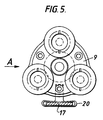
- the device to be inserted into the main 2 is a conventional closed circuit pipe wall inspection television camera as seen at 9 in Figures 5 and 6.
- the camera 9 has bolted thereto a skid 20 to receive the spring 17 as shown in the drawings.
- the camera 9 is releasably attached at one end via a connector 21 to a flexible camera cable 22.
- the other end of the cable 22 (not shown) is, in use, attached to a data interface port, television monitor, video recorder and printer.
- the sequence of operations for guiding the camera 9 along the main 1 is as follows. With the uppermost portion 12 of the insertion tube 5 temporarily removed from the lowermost portion 14 and clear thereof, the end of the cable 22 is pushed through the rubber gland 18 which has a central aperture for the purpose and into the tube 6 then through the shoe 16 until it reaches the spring 17.
- the camera skid 20 is then fitted onto the bag spring 17 and the cable 22 is connected to the connector 21.
- the aperture in the gland 18 is so dimensioned that the gland 18 forms a seal round the cable 22. It will be appreciated that at this stage the closure plate in the plate valve 4 is closed to prevent the escape of gas from the main.
- the uppermost portion 12 of the insertion tube 5 is then reconnected to the lowermost portion 14.
- the bag spring 17 curves at the end 24 which is introduced into the main 2, then providing that the curve is pointing in the correct direction, the camera 9 will always be guided in the required direction along the interior of the main 2.
- the cable 22 is pulled back through the gland 18 until the camera 8 has been withdrawn through the open plate valve 4 which is then closed and into the portion 4.
- the insertion tube 6 is withdrawn upwards inside insertion tube 5 and is then removed from the plate valve 4.
- the portions 12 and 14 are wound back out from the main 2 until a collar (not shown) at the lowermost end of the portion 14 is clear of the plate valve 4.
- the hole 3 in the wall of the main 2 can be plugged, e.g. by means of a non-tap plug before the plate valve 4 is removed.
- the device described is a television camera, the device could be any other piece of equipment used inside pipes and mains such as a spray device for spraying a sealant on the internal wall of the main.
Abstract
Description
- The present invention relates to guiding a device in a required direction along the interior of a pipe.
- It is known to guide devices along the interior of pipe for such purposes as inspecting the interior wall of the pipe (in which case the device is a closed circuit television camera) or spraying the wall with a sealant (in which case the device is a spray head).
- The devices are usually introduced into the pipe via a hole bored in the wall of the pipe. It is, of course, important to ensure that upon introduction into the pipe the device is guided in the correct direction and this can be very much a hit or miss affair.
- In known techniques of seeking to ensure that the device travels in the correct direction, entry pipes or tubes are provided arranged at an angle to the vertical to carry the device into the pipe via the bored hole to ensure the device travels in the selected direction. However, the disadvantage of these techniques is that the entry tubes reduce the overall size of the device which can be introduced into the pipe as the device is introduced at an angle to the hole in the pipe wall.
- It is therefore an object of the present invention to overcome this disadvantage.
- According to one aspect of the present invention there is provided a method for guiding a device in a required direction along the interior of a pipe, the method comprising removably mounting the device on a curved guide, lowering the device and the guide through a hole bored in the wall of the pipe to gain access to the interior of the pipe with the guide arranged to curve in the required direction in which the device is to move along the pipe and moving the device off the guide in the required direction.
- According to another aspect of the present invention there is provided apparatus for guiding a device in a required direction along the interior of a pipe, the apparatus comprising a curved guide upon which, in use, the device is mounted and means for removably mounting the device on the guide, the arrangement being that, in use, the device and guide are lowered through a hole bored in the wall of the pipe to gain access to the interior of the pipe with the guide arranged to curve in the required direction in which the device is to move along the pipe and the device is moved off the guide in the required direction.
- Preferably the guide is a spring which may be a bag-tube spring.
- Suitably the device is removably mounted on the guide by means of a skid.
- Because the device can be introduced substantially vertically to the axis of the pipe, the full bore of the hole in the pipe wall can be used.
- An embodiment of the invention will now be particularly described with reference to the accompanying drawings in which:-
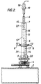
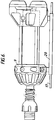
- Figure 1 shows an insertion tube in position on a pipe such as a main carrying gas under pressure before the introduction of a device such as an inspection camera,
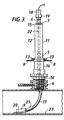
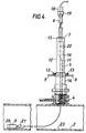
- Figures 2 to 4 comprise longitudinal sections through the insertion tube and the main showing a sequence of operations for guiding the camera along the main.
- Figure 5 shows a front view of a typical closed circuit television camera incorporating a skid, and
- Figure 6 is a view in the direction of A in Figure 5.
- Referring to the drawings, in the situation shown in Figure 1, an excavation 1 has been dug so as to reveal a portion of a live gas main 2.
- In figures 2 to 4 a hole 3 has been drilled in the wall of the main 2.
- In the known technique used here to drill the hole an Iris
plate valve 4 manufactured by ALH Systems Ltd is mounted on the main 2. An underpressure drill (not shown) is fitted to theplate valve 4 and operated to cut the hole 3 through the main (Figures 1 and 2). - A conventional construction and
design insertion tube 5 is then fitted to theplate valve 4 in place of the underpressure drill in the well known manner. - The
insertion tube 5 is bolted to the uppermost surface of theplate valve 4 in the well known manner and a known-typecable insertion tube 6 mounted in theinsertion tube 5 is arranged so that a direction indicator on apointer clamp plate 7 points in the direction in which adevice 8 to be inserted into the main 2 is required to go. By unbolting theinsertion tube 5 from theplate valve 4 by means of thehandles 8 and rotating it through 180° and rebolting it to theplate valve 4, thedevice 9 can be pushed into the main in two opposite directions, thereby enabling both directions to be inspected from one drilling. - The
insertion tube 5 has a main tubularouter body 11 having auppermost portion 12, and detachablyremovable allen screws 13 and a lowermost flangedportion 14 for bolting to theplate valve 4. Theportion 12 is externally threaded while theflange portion 14 is correspondingly internally threaded to receive the threaded portion of theuppermost portion 12. This arrangement enables theportions portion 14. Thecable insertion tube 6 extends through theportion 12 and forms a seal with theupper end 15 of theportion 12. Thecable insertion tube 6 has alowermost shoe piece 16 secured to the inside wall of which is secured one end of a flat steel "bag"spring 17. The term "bag" is used since in normal use of theinsertion tubes spring 17 is used to insert inflatable flow stopper bags into the gas pipe temporarily to stop the flow therein, the inflatable bag being connected to the other lowermost end of thespring 17. As shown in the drawings thespring 17 is curved as conventional to ensure that thedevice 9 to be inserted into the main travels in the correct direction. - The
camera insertion tube 6 also has arubber gland 18 mounted in asocket 19 at its uppermost end for purposes to be described. - In the case of this invention the device to be inserted into the main 2 is a conventional closed circuit pipe wall inspection television camera as seen at 9 in Figures 5 and 6. The
camera 9 has bolted thereto askid 20 to receive thespring 17 as shown in the drawings. - The
camera 9 is releasably attached at one end via aconnector 21 to aflexible camera cable 22. The other end of the cable 22 (not shown) is, in use, attached to a data interface port, television monitor, video recorder and printer. - Referring to Figures 2 to 4, the sequence of operations for guiding the
camera 9 along the main 1 is as follows. With theuppermost portion 12 of theinsertion tube 5 temporarily removed from thelowermost portion 14 and clear thereof, the end of thecable 22 is pushed through therubber gland 18 which has a central aperture for the purpose and into thetube 6 then through theshoe 16 until it reaches thespring 17. - The camera skid 20 is then fitted onto the
bag spring 17 and thecable 22 is connected to theconnector 21. The aperture in thegland 18 is so dimensioned that thegland 18 forms a seal round thecable 22. It will be appreciated that at this stage the closure plate in theplate valve 4 is closed to prevent the escape of gas from the main. Theuppermost portion 12 of theinsertion tube 5 is then reconnected to thelowermost portion 14. - In the next stage of the process (Figure 3) the
plate 9 in theplate valve 4 is opened and theportion 12 is wound down into theflanged portion 4 through theplate valve 4 and into the pipe wall 3 thecamera 9 is pushed into the interior of the main 2 by pushing thecable insertion tube 6 downwardly through themain insertion tube 5 until thespring 17 engages theinternal wall 23 of the main 2 as shown in Figure 3. - Next the
camera cable 22 is fed through thegland 18 so that thecamera 9 is caused to detach from thebag spring 17 and move along the main 2 as far as possible relaying pictures back to the monitor (Figure 4). - Because the
bag spring 17 curves at the end 24 which is introduced into the main 2, then providing that the curve is pointing in the correct direction, thecamera 9 will always be guided in the required direction along the interior of the main 2. - To remove the
camera 9 from the main 2, thecable 22 is pulled back through thegland 18 until thecamera 8 has been withdrawn through theopen plate valve 4 which is then closed and into theportion 4. - The
insertion tube 6 is withdrawn upwards insideinsertion tube 5 and is then removed from theplate valve 4. Theportions portion 14 is clear of theplate valve 4. Using any well known technique the hole 3 in the wall of the main 2 can be plugged, e.g. by means of a non-tap plug before theplate valve 4 is removed. - While the device described is a television camera, the device could be any other piece of equipment used inside pipes and mains such as a spray device for spraying a sealant on the internal wall of the main.
Claims (10)
- A method for guiding a device in a required direction along the interior of a pipe, the method comprising removably mounting the device on a curved guide, lowering the device and the guide through a hole bored in the wall of the pipe to gain access to the interior of the pipe with the guide arranged to curve in the required direction in which the device is to move along the pipe and moving the device off the guide in the required direction.
- A method as claimed in claim 1 in which the guide is a spring.
- A method as claimed in claim 2 in which the spring is a bag tube spring.
- A method as claimed in any of claims 1 to 3 in which the device is removably mounted on the guide by means of a skid.
- Apparatus for guiding a device in a required direction along the interior of a pipe, the apparatus comprising a curved guide upon which, in use, the device is mounted and means for removably mounting the device on the guide, the arrangement being that, in use, the device and guide are lowered through a hole bored in the wall of the pipe to gain access to the interior of the pipe with the guide arranged to curve in the required direction in which the device is to move along the pipe and the device is moved off the guide in the required direction.
- Apparatus as claimed in claim 5 in which the guide is a spring.
- Apparatus as claimed in claim 6 in which the spring is a bag tube spring.
- Apparatus as claimed in any of claims 5 to 7 in which the means is a skid for removably mounting the device on the guide.
- A method substantially as hereinbefore described with reference to the drawings.
- Apparatus substantially as hereinbefore described with reference to the drawings.
Applications Claiming Priority (4)
| Application Number | Priority Date | Filing Date | Title |
|---|---|---|---|
| GB9418196 | 1994-09-09 | ||
| GB9418196A GB9418196D0 (en) | 1994-09-09 | 1994-09-09 | Inspection of mains |
| GB9508958A GB2292987B (en) | 1994-09-09 | 1995-05-03 | Guiding of a device |
| GB9508958 | 1995-05-03 |
Publications (3)
| Publication Number | Publication Date |
|---|---|
| EP0701085A2 true EP0701085A2 (en) | 1996-03-13 |
| EP0701085A3 EP0701085A3 (en) | 1996-07-31 |
| EP0701085B1 EP0701085B1 (en) | 2002-03-27 |
Family
ID=26305598
Family Applications (1)
| Application Number | Title | Priority Date | Filing Date |
|---|---|---|---|
| EP95306284A Expired - Lifetime EP0701085B1 (en) | 1994-09-09 | 1995-09-07 | Method of guiding of a device and apparatus to guide a device in a required direction |
Country Status (4)
| Country | Link |
|---|---|
| US (1) | US5823115A (en) |
| EP (1) | EP0701085B1 (en) |
| DE (1) | DE69526014T2 (en) |
| ES (1) | ES2174901T3 (en) |
Cited By (4)
| Publication number | Priority date | Publication date | Assignee | Title |
|---|---|---|---|---|
| WO1999040357A1 (en) * | 1998-02-05 | 1999-08-12 | Bg Plc | Cable guide for pipes |
| EP0945668A3 (en) * | 1998-03-23 | 2001-03-14 | BG plc | Fluid pressure testing |
| DE19953423A1 (en) * | 1999-11-06 | 2001-05-10 | Jt Elektronik Gmbh | Inspection of underground pressure pipes for fresh water or gas, by lowing testing unit through connection unit placed on hydrant |
| WO2002021037A1 (en) * | 2000-09-05 | 2002-03-14 | Lattice Intellectual Property Ltd. | Method and apparatus for inserting rodlike tools into pipelines |
Families Citing this family (3)
| Publication number | Priority date | Publication date | Assignee | Title |
|---|---|---|---|---|
| US7551197B2 (en) * | 2005-09-08 | 2009-06-23 | Ulc Robotics, Inc. | Pipeline inspection system |
| EP3106735A1 (en) * | 2015-06-19 | 2016-12-21 | ULC Robotics, Inc. | Launch system for a pressurized pipeline |
| CN107012272A (en) * | 2017-04-26 | 2017-08-04 | 河钢股份有限公司邯郸分公司 | A kind of pipe lining device of blast furnace cooling stave bad water pipe |
Family Cites Families (8)
| Publication number | Priority date | Publication date | Assignee | Title |
|---|---|---|---|---|
| CH492159A (en) * | 1968-05-14 | 1970-06-15 | Arx Paul Von | Device for guiding a rope in a pipe |
| US3794340A (en) * | 1972-07-13 | 1974-02-26 | United Survey Inc | Adjustable skid for pipe inspection or survey equipment |
| FR2381657A1 (en) * | 1977-02-24 | 1978-09-22 | Commissariat Energie Atomique | SELF-PROPELLED VEHICLE WITH ARTICULATED ARMS |
| US4212248A (en) * | 1978-03-02 | 1980-07-15 | Brown & Root, Inc. | Apparatus and method for reducing interline twisting |
| JP2609149B2 (en) * | 1989-05-16 | 1997-05-14 | 大阪瓦斯株式会社 | Live pipe repair equipment for existing gas pipe joints |
| US5025670A (en) * | 1990-05-30 | 1991-06-25 | Mcnulty George R | Means for introducing inspection equipment in active pipelines |
| GB2247504B (en) * | 1990-08-20 | 1994-05-18 | British Gas Plc | Pipe fitting |
| US5203646A (en) * | 1992-02-06 | 1993-04-20 | Cornell Research Foundation, Inc. | Cable crawling underwater inspection and cleaning robot |
-
1995
- 1995-09-05 US US08/523,250 patent/US5823115A/en not_active Expired - Fee Related
- 1995-09-07 EP EP95306284A patent/EP0701085B1/en not_active Expired - Lifetime
- 1995-09-07 ES ES95306284T patent/ES2174901T3/en not_active Expired - Lifetime
- 1995-09-07 DE DE69526014T patent/DE69526014T2/en not_active Expired - Fee Related
Non-Patent Citations (1)
| Title |
|---|
| None |
Cited By (5)
| Publication number | Priority date | Publication date | Assignee | Title |
|---|---|---|---|---|
| WO1999040357A1 (en) * | 1998-02-05 | 1999-08-12 | Bg Plc | Cable guide for pipes |
| US6394701B1 (en) * | 1998-02-05 | 2002-05-28 | Lattice Intellectual Property Limited | Cable guide for pipes |
| EP0945668A3 (en) * | 1998-03-23 | 2001-03-14 | BG plc | Fluid pressure testing |
| DE19953423A1 (en) * | 1999-11-06 | 2001-05-10 | Jt Elektronik Gmbh | Inspection of underground pressure pipes for fresh water or gas, by lowing testing unit through connection unit placed on hydrant |
| WO2002021037A1 (en) * | 2000-09-05 | 2002-03-14 | Lattice Intellectual Property Ltd. | Method and apparatus for inserting rodlike tools into pipelines |
Also Published As
| Publication number | Publication date |
|---|---|
| DE69526014T2 (en) | 2002-10-02 |
| US5823115A (en) | 1998-10-20 |
| DE69526014D1 (en) | 2002-05-02 |
| EP0701085A3 (en) | 1996-07-31 |
| ES2174901T3 (en) | 2002-11-16 |
| EP0701085B1 (en) | 2002-03-27 |
Similar Documents
| Publication | Publication Date | Title |
|---|---|---|
| EP0701084A2 (en) | Guiding of a device | |
| US20020040731A1 (en) | Method and system for installing cable in pressurized pipelines | |
| US5823115A (en) | Guiding of a pipe travelling device | |
| HUT56965A (en) | Device for testing inside of branch pipe system | |
| EP0736722B1 (en) | Apparatus and method for introducing into and removing from a pipe a device which is advanced and retracted by a cable | |
| AU1698388A (en) | Pipeline systems | |
| US20120300057A1 (en) | Self-contained signal carrier for plumbing & methods of use thereof | |
| US7100274B2 (en) | Apparatus for applying media to a conduit | |
| GB2292987A (en) | Pig launcher | |
| US6394701B1 (en) | Cable guide for pipes | |
| GB2450621A (en) | Camera with inflatable support | |
| US20040079929A1 (en) | Pipe threading | |
| US6691734B2 (en) | Methods and systems for installing cable and conduit in pipelines | |
| GB2247505A (en) | Pipe access equipment | |
| US6536463B1 (en) | Method and system for installing cable in pressurized pipelines | |
| US6269877B1 (en) | Magnetic assembly for use with a downhole casing perforator | |
| EP1422465B1 (en) | Method of fitting a cable into a pipe | |
| GB2368891A (en) | Method for inserting a rodded tool into a pipe | |
| EP1051785B1 (en) | Pipe threading arrangement | |
| US6691728B2 (en) | Methods and systems for installing a pipeline within a pipeline | |
| GB2244109A (en) | Pipe fitting for launching a camera | |
| GB2600755A (en) | Valve body access adapter | |
| FR2387740A1 (en) | Gas mains tap plug extracting tool - draws plug through obturator of portable tap which is then rotated to maintain seal | |
| DE4425161A1 (en) | Natural gas line swabbing pig | |
| EP0646050A1 (en) | Line cleaning system and measurement |
Legal Events
| Date | Code | Title | Description |
|---|---|---|---|
| PUAI | Public reference made under article 153(3) epc to a published international application that has entered the european phase |
Free format text: ORIGINAL CODE: 0009012 |
|
| 17P | Request for examination filed |
Effective date: 19951002 |
|
| AK | Designated contracting states |
Kind code of ref document: A2 Designated state(s): BE DE ES FR GB IT NL SE |
|
| PUAL | Search report despatched |
Free format text: ORIGINAL CODE: 0009013 |
|
| AK | Designated contracting states |
Kind code of ref document: A3 Designated state(s): BE DE ES FR GB IT NL SE |
|
| RAP1 | Party data changed (applicant data changed or rights of an application transferred) |
Owner name: BG PUBLIC LIMITED COMPANY |
|
| RAP1 | Party data changed (applicant data changed or rights of an application transferred) |
Owner name: BG PLC |
|
| 17Q | First examination report despatched |
Effective date: 19990701 |
|
| GRAG | Despatch of communication of intention to grant |
Free format text: ORIGINAL CODE: EPIDOS AGRA |
|
| RTI1 | Title (correction) |
Free format text: METHOD OF GUIDING OF A DEVICE AND APPARATUS TO GUIDE A DEVICE IN A REQUIRED DIRECTION |
|
| RTI1 | Title (correction) |
Free format text: METHOD OF GUIDING OF A DEVICE AND APPARATUS TO GUIDE A DEVICE IN A REQUIRED DIRECTION |
|
| GRAG | Despatch of communication of intention to grant |
Free format text: ORIGINAL CODE: EPIDOS AGRA |
|
| RAP1 | Party data changed (applicant data changed or rights of an application transferred) |
Owner name: LATTICE INTELLECTUAL PROPERTY LIMITED |
|
| GRAG | Despatch of communication of intention to grant |
Free format text: ORIGINAL CODE: EPIDOS AGRA |
|
| GRAH | Despatch of communication of intention to grant a patent |
Free format text: ORIGINAL CODE: EPIDOS IGRA |
|
| GRAH | Despatch of communication of intention to grant a patent |
Free format text: ORIGINAL CODE: EPIDOS IGRA |
|
| REG | Reference to a national code |
Ref country code: GB Ref legal event code: IF02 |
|
| GRAA | (expected) grant |
Free format text: ORIGINAL CODE: 0009210 |
|
| AK | Designated contracting states |
Kind code of ref document: B1 Designated state(s): BE DE ES FR GB IT NL SE |
|
| REF | Corresponds to: |
Ref document number: 69526014 Country of ref document: DE Date of ref document: 20020502 |
|
| ET | Fr: translation filed | ||
| PGFP | Annual fee paid to national office [announced via postgrant information from national office to epo] |
Ref country code: FR Payment date: 20020812 Year of fee payment: 8 |
|
| PGFP | Annual fee paid to national office [announced via postgrant information from national office to epo] |
Ref country code: NL Payment date: 20020815 Year of fee payment: 8 Ref country code: GB Payment date: 20020815 Year of fee payment: 8 |
|
| PGFP | Annual fee paid to national office [announced via postgrant information from national office to epo] |
Ref country code: SE Payment date: 20020821 Year of fee payment: 8 |
|
| PGFP | Annual fee paid to national office [announced via postgrant information from national office to epo] |
Ref country code: DE Payment date: 20020822 Year of fee payment: 8 |
|
| PGFP | Annual fee paid to national office [announced via postgrant information from national office to epo] |
Ref country code: BE Payment date: 20020903 Year of fee payment: 8 |
|
| PGFP | Annual fee paid to national office [announced via postgrant information from national office to epo] |
Ref country code: ES Payment date: 20020910 Year of fee payment: 8 |
|
| REG | Reference to a national code |
Ref country code: ES Ref legal event code: FG2A Ref document number: 2174901 Country of ref document: ES Kind code of ref document: T3 |
|
| PLBE | No opposition filed within time limit |
Free format text: ORIGINAL CODE: 0009261 |
|
| STAA | Information on the status of an ep patent application or granted ep patent |
Free format text: STATUS: NO OPPOSITION FILED WITHIN TIME LIMIT |
|
| 26N | No opposition filed |
Effective date: 20021230 |
|
| PG25 | Lapsed in a contracting state [announced via postgrant information from national office to epo] |
Ref country code: GB Free format text: LAPSE BECAUSE OF NON-PAYMENT OF DUE FEES Effective date: 20030907 |
|
| PG25 | Lapsed in a contracting state [announced via postgrant information from national office to epo] |
Ref country code: SE Free format text: LAPSE BECAUSE OF NON-PAYMENT OF DUE FEES Effective date: 20030908 Ref country code: ES Free format text: LAPSE BECAUSE OF NON-PAYMENT OF DUE FEES Effective date: 20030908 |
|
| PG25 | Lapsed in a contracting state [announced via postgrant information from national office to epo] |
Ref country code: BE Free format text: LAPSE BECAUSE OF NON-PAYMENT OF DUE FEES Effective date: 20030930 |
|
| BERE | Be: lapsed |
Owner name: *LATTICE INTELLECTUAL PROPERTY LTD Effective date: 20030930 |
|
| PG25 | Lapsed in a contracting state [announced via postgrant information from national office to epo] |
Ref country code: NL Free format text: LAPSE BECAUSE OF NON-PAYMENT OF DUE FEES Effective date: 20040401 Ref country code: DE Free format text: LAPSE BECAUSE OF NON-PAYMENT OF DUE FEES Effective date: 20040401 |
|
| GBPC | Gb: european patent ceased through non-payment of renewal fee |
Effective date: 20030907 |
|
| EUG | Se: european patent has lapsed | ||
| PG25 | Lapsed in a contracting state [announced via postgrant information from national office to epo] |
Ref country code: FR Free format text: LAPSE BECAUSE OF NON-PAYMENT OF DUE FEES Effective date: 20040528 |
|
| NLV4 | Nl: lapsed or anulled due to non-payment of the annual fee |
Effective date: 20040401 |
|
| REG | Reference to a national code |
Ref country code: FR Ref legal event code: ST |
|
| REG | Reference to a national code |
Ref country code: ES Ref legal event code: FD2A Effective date: 20030908 |
|
| PG25 | Lapsed in a contracting state [announced via postgrant information from national office to epo] |
Ref country code: IT Free format text: LAPSE BECAUSE OF NON-PAYMENT OF DUE FEES Effective date: 20050907 |