EP0699272B1 - High efficiency multi-shaft reheat turbine with intercooling and recuperation - Google Patents
High efficiency multi-shaft reheat turbine with intercooling and recuperation Download PDFInfo
- Publication number
- EP0699272B1 EP0699272B1 EP94914096A EP94914096A EP0699272B1 EP 0699272 B1 EP0699272 B1 EP 0699272B1 EP 94914096 A EP94914096 A EP 94914096A EP 94914096 A EP94914096 A EP 94914096A EP 0699272 B1 EP0699272 B1 EP 0699272B1
- Authority
- EP
- European Patent Office
- Prior art keywords
- shaft assembly
- compressor
- turbine
- expansion turbine
- additional shaft
- Prior art date
- Legal status (The legal status is an assumption and is not a legal conclusion. Google has not performed a legal analysis and makes no representation as to the accuracy of the status listed.)
- Expired - Lifetime
Links
Images

Classifications
-
- F—MECHANICAL ENGINEERING; LIGHTING; HEATING; WEAPONS; BLASTING
- F01—MACHINES OR ENGINES IN GENERAL; ENGINE PLANTS IN GENERAL; STEAM ENGINES
- F01K—STEAM ENGINE PLANTS; STEAM ACCUMULATORS; ENGINE PLANTS NOT OTHERWISE PROVIDED FOR; ENGINES USING SPECIAL WORKING FLUIDS OR CYCLES
- F01K21/00—Steam engine plants not otherwise provided for
- F01K21/04—Steam engine plants not otherwise provided for using mixtures of steam and gas; Plants generating or heating steam by bringing water or steam into direct contact with hot gas
- F01K21/047—Steam engine plants not otherwise provided for using mixtures of steam and gas; Plants generating or heating steam by bringing water or steam into direct contact with hot gas having at least one combustion gas turbine
-
- F—MECHANICAL ENGINEERING; LIGHTING; HEATING; WEAPONS; BLASTING
- F02—COMBUSTION ENGINES; HOT-GAS OR COMBUSTION-PRODUCT ENGINE PLANTS
- F02C—GAS-TURBINE PLANTS; AIR INTAKES FOR JET-PROPULSION PLANTS; CONTROLLING FUEL SUPPLY IN AIR-BREATHING JET-PROPULSION PLANTS
- F02C3/00—Gas-turbine plants characterised by the use of combustion products as the working fluid
- F02C3/36—Open cycles
-
- F—MECHANICAL ENGINEERING; LIGHTING; HEATING; WEAPONS; BLASTING
- F02—COMBUSTION ENGINES; HOT-GAS OR COMBUSTION-PRODUCT ENGINE PLANTS
- F02C—GAS-TURBINE PLANTS; AIR INTAKES FOR JET-PROPULSION PLANTS; CONTROLLING FUEL SUPPLY IN AIR-BREATHING JET-PROPULSION PLANTS
- F02C6/00—Plural gas-turbine plants; Combinations of gas-turbine plants with other apparatus; Adaptations of gas- turbine plants for special use
- F02C6/003—Gas-turbine plants with heaters between turbine stages
-
- F—MECHANICAL ENGINEERING; LIGHTING; HEATING; WEAPONS; BLASTING
- F05—INDEXING SCHEMES RELATING TO ENGINES OR PUMPS IN VARIOUS SUBCLASSES OF CLASSES F01-F04
- F05D—INDEXING SCHEME FOR ASPECTS RELATING TO NON-POSITIVE-DISPLACEMENT MACHINES OR ENGINES, GAS-TURBINES OR JET-PROPULSION PLANTS
- F05D2220/00—Application
- F05D2220/60—Application making use of surplus or waste energy
-
- F—MECHANICAL ENGINEERING; LIGHTING; HEATING; WEAPONS; BLASTING
- F05—INDEXING SCHEMES RELATING TO ENGINES OR PUMPS IN VARIOUS SUBCLASSES OF CLASSES F01-F04
- F05D—INDEXING SCHEME FOR ASPECTS RELATING TO NON-POSITIVE-DISPLACEMENT MACHINES OR ENGINES, GAS-TURBINES OR JET-PROPULSION PLANTS
- F05D2260/00—Function
- F05D2260/20—Heat transfer, e.g. cooling
- F05D2260/211—Heat transfer, e.g. cooling by intercooling, e.g. during a compression cycle
-
- Y—GENERAL TAGGING OF NEW TECHNOLOGICAL DEVELOPMENTS; GENERAL TAGGING OF CROSS-SECTIONAL TECHNOLOGIES SPANNING OVER SEVERAL SECTIONS OF THE IPC; TECHNICAL SUBJECTS COVERED BY FORMER USPC CROSS-REFERENCE ART COLLECTIONS [XRACs] AND DIGESTS
- Y02—TECHNOLOGIES OR APPLICATIONS FOR MITIGATION OR ADAPTATION AGAINST CLIMATE CHANGE
- Y02T—CLIMATE CHANGE MITIGATION TECHNOLOGIES RELATED TO TRANSPORTATION
- Y02T50/00—Aeronautics or air transport
- Y02T50/60—Efficient propulsion technologies, e.g. for aircraft
Definitions
- This invention relates to combustion turbine engines with inter cooling, saturation, recuperation and reheat.
- a typical and currently available simple cycle combustion turbine consists of a compressor for compressing the atmospheric air, a combustor for heating the compressed air, a turbine for power production and an electric generator for converting mechanical energy into electrical energy.
- a more sophisticated combustion turbine concept with a number of compressors with intercoolers and with a number of turbines with associated combustors and, also, with a recuperator, has been theoretically known at least since the 1920's.
- the first and the most important engineering problem is that the highest pressure turbine for the prior art combustion turbine concept has the highest inlet temperature. This presents a serious challenge because of high thermal and transient stresses in the high pressure and temperature turbine components, and requires special materials and engineering yet to be developed.
- the second engineering problem is a result of the fact that for a typical prior art concept a plurality of combustion turbines with the same inlet temperatures and equal pressure ratios have very high exhaust gas flow temperatures which are the inlet temperatures for a plurality of downstream combustors. This is yet another serious engineering challenge.
- US-A-2115338 describes a gas turbine system having a high pressure turbine and a low pressure turbine.
- the system described further includes two compressors, two coolers, two combustion chambers and a heat exchanger.
- An object of this invention is to develop a new combustion turbine with improved efficiency and economics which embodies a properly integrated plurality of turbines with reheat, a plurality of compressors with intercoolers, a recuperator, saturator, water heaters, duct burners, and a heat recovery steam generator.
- Another object of this invention is to develop a new thermal cycle with reduced inlet temperatures (as compared to the current level of temperatures for industrial expanders) to a plurality of turbines which have inlet pressures exceeding the level of the conventional inlet turbine pressure for simple cycle combustion turbines. This resolves the first and the most important engineering problem: a prohibitive combination of coincidental high pressures and temperatures.
- Still another object of this invention is to reduce the gas flow temperatures entering a plurality of combustors. This resolves the second engineering problem.
- Yet another object of this invention is an integration of a saturator in the combustion turbine concept to improve the combustion turbine thermal efficiency and to increase the specific production of electric power per pound of air.
- the saturator via heat and mass exchange, preheats the compressed air and saturates it with moisture before entering a recuperator.
- Another object of the invention is to incorporate a recuperator and water heaters into the inventive combustion turbine concept for better utilization of the combustion turbine cycle available heat with associated improvement of the thermal efficiency.
- Still another object of the invention is a maximum utilization of the available prior art simple cycle combustion turbine components with the addition of currently available industrial components properly integrated into the inventive cycle in order to facilitate practical implementation of the inventive concept.
- Yet a further object of this invention is to provide a heat recovery steam generator for the alternative utilization of the exhaust gas heat, for steam use in the bottoming cycle and/or for steam injection into one of the plurality of turbines.
- a further object of the invention is to provide duct burners strategically positioned in locations of the system to improve the efficiency and economics of the system further.
- an electric power generation system comprising:
- Also provided by the invention is a method for providing an electric power generating system including an electric generator by modifying a conventional power shaft assembly having a compressor, an expansion turbine, a combustor feeding said expansion turbine, and means for coupling said expansion turbine to drive said compressor and said electric generator, the method including the steps of:
- an electric power generating system which comprises an electric generator and a power shaft assembly including a compressor, an expansion turbine, a combustor feeding heated air to the expansion turbine, and means for coupling the expansion turbine to drive the compressor and the electric generator.
- At least one additional shaft assembly is provided.
- each additional shaft assembly includes a compressor, an intercooler, an expansion turbine, a combustor, and means for coupling the expansion turbine of the additional shaft assembly to drive the compressor of the additional shaft assembly.
- a recuperator and optional duct burners are provided.
- the power shaft assembly, the at least one additional shaft assembly, and the recuperator are connected to define an air and gas path that passes through the compressor of the power shaft assembly, through the intercooler and the compressor of each of the at least one additional shaft assembly-in a first predetermined ordered sequence, through the recuperator, through the combustor and the expansion turbine of each of the at least one additional shaft assembly in a second predetermined ordered sequence, through the combustor and expansion turbine of the power shaft assembly, through the recuperator and to the exhaust stack.
- incoming air is alternately compressed and cooled as it passes through the compressors of the power and additional shaft assemblies, is heated in the heat recuperator, and is alternately heated and expanded as its combustion product gas passes through the combustors and the expansion turbines of the additional and power shaft assemblies.
- the water for the inter-coolers is provided from either a cooling tower or other source.
- a new combustion turbine thermal cycle has been developed with major parameters and other features different from the prior art.
- the resulting cycle has a significantly higher efficiency as compared to the state-of-the art combustion turbine.
- This thermal cycle simultaneously resolves major engineering problems thus ensuring its practical implementation.
- the compression pressure ratio of the compressor is greater than the expansion pressure ratio of the expansion turbine. Therefore, for total pressure balance the compression pressure ratio of the power shaft assembly compressor is less than the expansion pressure ratio of the power shaft assembly expansion turbine. In effect, the compressor of the power shaft assembly is partially unloaded so that the expansion turbine of the power shaft assembly can supply more of its power to the electric generator.
- exhaust gas from the power shaft assembly expansion turbine is directed to the heat recuperator so as to provide a heat source therefor.
- the multi-shaft arrangement (power shaft and at least one additional shaft assembly) provides for convenient and economical location of inter-coolers. This allows an increase in the pressure ratio of compressors of the power balanced additional shaft assemblies, thus further unloading the compressor of the power shaft assembly, which, in turn, provides additional power for electric power generation and increases efficiency.
- the saturator saturates the compressed air, thus further reducing the air requirements per kilowatt-hour produced with associated reduction of power consumption by the compressors of the additional shaft assemblies and by the compressor of the power shaft assembly.
- hot water-required for the compressed air saturation in the saturator is produced in water heaters (recovering the heat available in the exhaust gas leaving the power shaft assembly turbine after partial heat recovery in the recuperator) and in the intercoolers and aftercooler (recovering the compressed air heat).
- the steam generated in the heat recovery steam generator produces additional power via steam injection or in the bottoming cycle.
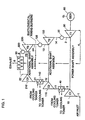
- FIG. 1 is a schematic representation of a first illustrative embodiment of an electric power generating system according to this invention.
- the power shaft assembly represents a conventional heavy duty combustion turbine or an aircraft derivative combustion turbine which includes the compressor 10, the expansion turbine 30, the combustor 20 which feeds heated combustion product gas to the expansion turbine 30, the expansion turbine 30 being coupled to drive the compressor 10 and the electric generator 60.
- air which enters the low pressure compressor 10 at its inlet 1 is compressed thereby and provided at its outlet 2.
- the compressed air is discharged directly to the low pressure combustor 20 and then expanded through the low pressure expansion turbine 30.
- the power output of the turbine 30 is substantially equally divided for driving the compressor 10 and the generator 60.
- At least one additional shaft assembly is provided to modify the conventional power shaft assembly described above.
- two additional shaft assemblies are shown.
- a heat recuperator 50 is provided.
- the first additional shaft assembly includes the intercooler 40, the intermediate pressure compressor 110, the intermediate pressure combustor 120 and the intermediate pressure expansion turbine 130.
- the second additional shaft assembly includes the high pressure intercooler 140, the high pressure compressor 210, the high pressure combustor 220 and the high pressure expansion turbine 230.
- the intercoolers 40 and 140 are cooled by water supplied from a cooling tower.
- the air and gas path extends through the modified compressor of the conventional power shaft assembly, through the intercoolers and compressors of the additional shaft assemblies, through the recuperator, through the combustors and expansion turbines of the additional shaft assemblies, and then through the combustor and expansion turbine of the conventional power shaft assembly.
- the exhaust 2 of the low pressure compressor 10 passes through the intercooler 40 which reduces its temperature at the inlet 11 of the intermediate compressor 110.
- the pressure of the air is then again raised and provided at the exhaust 12 of the compressor 110 to the intercooler 140 which lowers its temperature and provides the cooled intermediate pressure air at the inlet 21 to the high pressure compressor 210.
- the exhaust 22 of the high pressure compressor 210 is provided as an input to the heat recuperator 50.
- the outlet 5 of the heat recuperator 50 is connected to the high pressure combustor 220, whose outlet 23 is provided to the high pressure expansion turbine 230.
- the exhaust 24 of the high pressure expansion turbine 230 is heated in the intermediate pressure combustor 120 and then provided to the inlet 13 of the intermediate pressure expansion turbine 130.
- the exhaust 14 of the intermediate pressure expansion turbine 130 is heated in the low pressure combustor 20 and then provided to the inlet 3 of the low pressure expansion turbine 30, the exhaust 4 of which is utilized as a heat source for the heat recuperator 50, before going to the system exhaust 6.
- the thermodynamic cycle is shown as the temperature-entropy diagram of FIG. 2.
- the compression pressure ratio of the compressor equals the expansion pressure ratio of the turbine, and the output combustion turbine power from the turbine is substantially equally divided for driving the compressor and the electric generator.
- the compression pressure ratio of compressor 10 is substantially reduced so that turbine 30 can supply more of its power for driving generator 60.
- This lowering of the compression pressure ratio of the compressor 10 is accompanied by raising the overall compression pressure ratio of the additional shaft assemblies over the overall expansion pressure ratio of the additional shaft assemblies.
- the intercoolers 40 and 140 the temperature of the air entering the compressors 110 and 210 is reduced, which reduces the power consumed by the compressors 110 and 210, and for the same power consumption by the compressors allows for increased compression pressure ratios.
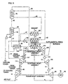
- FIG. 3 illustrates a modification to the system shown in FIG. 1 which further includes an aftercooler 240 and water saturators 170 and 70 connected between the output of the high pressure compressor 210 and the inlet of the heat recuperator 50.
- the compressed air is cooled in the aftercooler 240 and then directed into the inlet 31 of the saturator 170 and into the inlet 32 of the saturator 70, where the compressed air is saturated with water and preheated before entering the inlet 33 of the heat recuperator 50.
- the remainder of the air and gas path is identical to that of FIG. 1.
- the saturators 170 and 70 are fed by water which has been heated in intercooler 140 and aftercooler 240, and the exhaust gas heat recovering water heaters 65 and 165.
- the water flow paths, including the pumps 80 and 180, are readily apparent from FIG. 3. If desired, the recuperator 50 and the water heater 65 can be supplementally fired by the installation of duct burners.
- the system shown in FIG. 3 has been shown to have a significantly higher efficiency (up to approximately 53% with state of the art combustion turbines) over the basic system shown in FIG. 1 (approximately 47% efficiency), but the increased efficiency has some penalties.
- the system shown in FIG. 3 requires a significant amount of make-up water and therefore may have some siting limitations.
- the system shown in FIG. 3 with saturators is more complicated when compared with the basic system shown in FIG. 1, although it is significantly simpler in engineering and operation as compared to a combined cycle plant with a comparable efficiency.
- the specific capital cost, in dollars per kilowatt, for the system of FIG. 3 is only slightly higher than the cost of a simple cycle gas turbine.
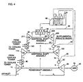
- FIG. 4 illustrates another modification to the system of FIG. 1 wherein the exhaust 6 from the heat recuperator 50 is directed to the heat recovery steam generator 90 to produce steam which may be injected into one or more of the combustors 20, 120 and 220.
- the remainder of the system is the same as that shown in FIG. 1.
- the inventive combustion turbine system is a multi-shaft combustion turbine system with a sophisticated thermodynamic cycle and significantly higher efficiency as compared to the state of the art combustion turbine with an estimated specific capital cost, in dollars per kilowatt hour, comparable to that of a simple cycle combustion turbine system.
- the inventive system resolves major engineering problems which until now have prevented an implementation of these sophisticated concepts.
- the system utilizes commercially available components and can be delivered skid mounted, thus shortening the construction time and reducing field construction and cost.
- TABLE 1 presents performance and key point parameters for the inventive system, which are compared to those for a simple cycle combustion turbine.
- the performance characteristics presented in TABLE 1 are based on the current level of technology development and on the performance characteristics of Westinghouse's W501F combustion turbine as the source of the power shaft assembly combustion turbine and the performance characteristics of commercial turbo-expanders and compressors for the additional shaft assemblies.
- TABLE 1 shows the advantages of other embodiments of the inventive concepts.
- the second embodiment (FIG 3) with the addition of a saturator, associated after cooler and waste heat water heaters, has a gross efficiency of 52.8%, as compared to an efficiency of 36.6% for the state of the art combustion turbine.
- TABLE 1 also shows that the third embodiment (FIG. 4) of the inventive concept with use of the heat recovery steam generator shows an efficiency of 48.5%.
- the power shaft assembly is a standard commercially available combustion turbine. The modifications required are relatively minor.
- the low pressure compressor 10 pressure ratio has to be reduced to below the pressure ratio of its associated expansion turbine.
- the power-balanced additional shaft assemblies have compression pressure ratios of compressors 110 and 210 which are higher than the corresponding expansion pressure ratios of the turbines 230 and 130. For the same overall compression pressure ratio, this in turn reduces the required compression pressure ratio for the low pressure compressor 10.
- the generator 60 is upgraded for the higher power generating capacity of the plant.
- the power shaft assembly is thrust balanced either by upgrading the existing thrust bearing or by the addition of an external thrust bearing connected to the power shaft assembly.
- the easiest way of reducing the pressure ratio of the compressor 10 is by de-blading a number of its last stages, which can be performed by a manufacturer or by any packager or any utility.
- the additional shaft assemblies can be supplied by industrial turbo-driven compressor manufacturers, supported by combustor manufacturers.
- the described multi-shaft combustion turbine can be commercially offered by combustion turbine manufacturers, industrial steam turbine and turbo machinery manufacturers and/or by other packagers.
- the system described herein is applicable to all alternative modifications of combustion turbines.
Abstract
Description
- This invention relates to combustion turbine engines with inter cooling, saturation, recuperation and reheat.
- A typical and currently available simple cycle combustion turbine consists of a compressor for compressing the atmospheric air, a combustor for heating the compressed air, a turbine for power production and an electric generator for converting mechanical energy into electrical energy. A more sophisticated combustion turbine concept with a number of compressors with intercoolers and with a number of turbines with associated combustors and, also, with a recuperator, has been theoretically known at least since the 1920's.
- Major features of the conventional, generic combustion turbine concept as disclosed in the article entitled "Optimization of Gas Turbine Cycles with Variable Number of Combustion, Compressor and Intercooler Stages", document no. 81-JPGC-CT-6 published in 1981 by the American Society of Mechanical Engineers, are as follows:
- The highest pressure turbine with associated combustor has the highest inlet temperature. The lower pressure turbines with associated combustors have the same (as the highest pressure turbine) inlet temperature;
- The expansion pressure ratios of all turbines are equal; and
- The compression pressure ratios of all compressors are equal. Earlier patents, for example, U.S. Patent No. 2,584,232 to Sedille utilize this generic theoretical combustion turbine cycle with the aforementioned features. The major thrust of these patents is the utilization of available and otherwise wasted heat resources of the generic theoretical combustion turbine concept for improving the resulting power plant efficiency. These heat resources are used for steam generation and additional electric power production by the bottoming steam turbine or via steam injection.
- No practical applications of this prior art theoretical combustion turbine cycle have been established, due to a number of engineering problems facing the power plant designers.
- The first and the most important engineering problem is that the highest pressure turbine for the prior art combustion turbine concept has the highest inlet temperature. This presents a serious challenge because of high thermal and transient stresses in the high pressure and temperature turbine components, and requires special materials and engineering yet to be developed.
- The second engineering problem is a result of the fact that for a typical prior art concept a plurality of combustion turbines with the same inlet temperatures and equal pressure ratios have very high exhaust gas flow temperatures which are the inlet temperatures for a plurality of downstream combustors. This is yet another serious engineering challenge.
- US-A-2115338 describes a gas turbine system having a high pressure turbine and a low pressure turbine. The system described further includes two compressors, two coolers, two combustion chambers and a heat exchanger.
- An object of this invention is to develop a new combustion turbine with improved efficiency and economics which embodies a properly integrated plurality of turbines with reheat, a plurality of compressors with intercoolers, a recuperator, saturator, water heaters, duct burners, and a heat recovery steam generator.
- Another object of this invention is to develop a new thermal cycle with reduced inlet temperatures (as compared to the current level of temperatures for industrial expanders) to a plurality of turbines which have inlet pressures exceeding the level of the conventional inlet turbine pressure for simple cycle combustion turbines. This resolves the first and the most important engineering problem: a prohibitive combination of coincidental high pressures and temperatures.
- Still another object of this invention is to reduce the gas flow temperatures entering a plurality of combustors. This resolves the second engineering problem.
- Yet another object of this invention is an integration of a saturator in the combustion turbine concept to improve the combustion turbine thermal efficiency and to increase the specific production of electric power per pound of air. The saturator, via heat and mass exchange, preheats the compressed air and saturates it with moisture before entering a recuperator.
- Another object of the invention is to incorporate a recuperator and water heaters into the inventive combustion turbine concept for better utilization of the combustion turbine cycle available heat with associated improvement of the thermal efficiency.
- Still another object of the invention is a maximum utilization of the available prior art simple cycle combustion turbine components with the addition of currently available industrial components properly integrated into the inventive cycle in order to facilitate practical implementation of the inventive concept.
- Yet a further object of this invention is to provide a heat recovery steam generator for the alternative utilization of the exhaust gas heat, for steam use in the bottoming cycle and/or for steam injection into one of the plurality of turbines.
- A further object of the invention is to provide duct burners strategically positioned in locations of the system to improve the efficiency and economics of the system further.
- According to the invention, there is provided an electric power generation system comprising:
- a single power shaft assembly including a combustion turbine having a compressor, an expansion turbine, a combustor feeding said expansion turbine, an electrical generator, and means for coupling said expansion turbine to drive said compressor and said electrical generator;
- at least one additional shaft assembly including an intercooler, a compressor, an expansion turbine, a combustor feeding said expansion turbine, and means for driving the compressor of the additional shaft assembly;
- a recuperator; and
- an exhaust stack,
- said single power shaft assembly, said at least one additional shaft assembly and said recuperator being connected to define a thermal cycle with an air and gas path that passes through the compressor of said single power shaft assembly, through the intercooler and compressor of said at least one additional shaft assembly, through said recuperator, through the combustor and expansion turbine of said at least one additional shaft assembly and through the combustor and expansion turbine of said single power shaft assembly, and finally exhausting through said recuperator to said exhaust stack, characterised in that
-
- Also provided by the invention is a method for providing an electric power generating system including an electric generator by modifying a conventional power shaft assembly having a compressor, an expansion turbine, a combustor feeding said expansion turbine, and means for coupling said expansion turbine to drive said compressor and said electric generator, the method including the steps of:
- providing at least one additional shaft assembly, each of said at least one additional shaft assembly including a compressor, an inter cooler feeding cooled air to said compressor, an industrial expansion turbine, a combustor feeding said expansion turbine, and means for coupling the expansion turbine of that additional shaft assembly to drive the compressor of that additional shaft assembly;
- providing a heat recuperator; and
- connecting said conventional power shaft assembly, said at least one additional shaft assembly, and said recuperator so as to modify the air and gas path of said conventional power shaft assembly so that the modified air and gas path passes through the compressor of said conventional power shaft assembly, through the inter cooler and compressor of each of said at least one additional shaft assembly in a first predetermined ordered sequence, through the heat recuperator, through the combustor and industrial expansion turbine of each of said at least one additional shaft assembly in a second predetermined ordered sequence, and through the combustor and expansion turbine of said conventional power shaft assembly;
- whereby incoming air is alternately compressed and cooled as it passes through the compressors of the power and additional shaft assemblies, is heated in the heat recuperator, and its combustion product gas is alternately heated and expanded as it passes through the combustors and expansion turbines of the additional and power shaft assemblies, characterised in that the compressor of the at least one additional shaft assembly has a pressure ratio greater than a pressure ratio of the expansion turbine of the at least one additional shaft assembly.
-
- The major theoretical and conceptual features of the invention are set forth in the new combustion turbine thermal cycle shown in FIG. 2 on a temperature-entry diagram.
- The foregoing, and additional, objects are attained in accordance with the principles of this invention by providing an electric power generating system which comprises an electric generator and a power shaft assembly including a compressor, an expansion turbine, a combustor feeding heated air to the expansion turbine, and means for coupling the expansion turbine to drive the compressor and the electric generator. At least one additional shaft assembly is provided. In embodiments of the invention, each additional shaft assembly includes a compressor, an intercooler, an expansion turbine, a combustor, and means for coupling the expansion turbine of the additional shaft assembly to drive the compressor of the additional shaft assembly. Further, a recuperator and optional duct burners are provided. According to embodiments of this invention, the power shaft assembly, the at least one additional shaft assembly, and the recuperator are connected to define an air and gas path that passes through the compressor of the power shaft assembly, through the intercooler and the compressor of each of the at least one additional shaft assembly-in a first predetermined ordered sequence, through the recuperator, through the combustor and the expansion turbine of each of the at least one additional shaft assembly in a second predetermined ordered sequence, through the combustor and expansion turbine of the power shaft assembly, through the recuperator and to the exhaust stack. Accordingly, incoming air is alternately compressed and cooled as it passes through the compressors of the power and additional shaft assemblies, is heated in the heat recuperator, and is alternately heated and expanded as its combustion product gas passes through the combustors and the expansion turbines of the additional and power shaft assemblies. The water for the inter-coolers is provided from either a cooling tower or other source.
- The major original features of embodiments of the inventive gas turbine concept are as follows (see FIG. 2) :
- The inlet temperature to the highest pressure turbine (FIG. 2, point 23), of the plurality of the additional shaft assemblies, has the lowest inlet temperature at the level of current industrial expander technology (760°C (1400° F)). The other turbines (point 13) of the additional shaft assemblies (except the lowest pressure turbine), have the same inlet temperature, or only slightly higher. The highest inlet temperature is at the inlet to the lowest pressure turbine (point 3) of the power shaft assembly and presents the current state of the art temperature level for combustion turbines (1260°C to 1376°C (2300°F to 2500°F)). This distribution of turbine inlet temperatures is in contrast with the prior art theoretical cycle as disclosed in U.S. Patent No. 2,584,232 and provides very high thermal cycle efficiency, making practical engineering sense. It addresses the first engineering problem of the prior art: a prohibitive coincidental high pressure and temperature at the high pressure turbine inlet.
- Consequently, the reduced inlet temperatures of the high and intermediate pressure turbines (of the additional shaft assemblies), reduce the inlet temperatures to the downstream combustors. This addresses the second engineering problem of the prior art cycle.
- The optimized distribution of the expansion pressure ratio among a plurality of turbines results in approximately equal pressure ratios for all turbines (of the additional shaft assemblies), except for the lowest pressure turbine (of the power shaft assembly). The lowest pressure turbine has the highest pressure ratio, corresponding to that of a combustion turbine, which components are utilized for the power shaft assembly. This allows the modification of an existing combustion turbine into the inventive concept - the major thrust of this invention.
- The optimized distribution of the overall compression ratio among compressors is dictated by considerations of the balanced high and intermediate pressure shafts (of the additional shaft assemblies) and is different from the equal distribution for the prior art cycle.
- The recuperator recovers the high temperature exhaust gas heat from the power shaft assembly turbine to preheat the air prior to entering the highest pressure combustor of the additional shaft assemblies.
- In accordance with a major aspect of embodiments of this invention, a new combustion turbine thermal cycle has been developed with major parameters and other features different from the prior art. The resulting cycle has a significantly higher efficiency as compared to the state-of-the art combustion turbine. This thermal cycle simultaneously resolves major engineering problems thus ensuring its practical implementation.
- In accordance with another aspect of embodiments of this invention, in each of the additional shart assemblies, the compression pressure ratio of the compressor is greater than the expansion pressure ratio of the expansion turbine. Therefore, for total pressure balance the compression pressure ratio of the power shaft assembly compressor is less than the expansion pressure ratio of the power shaft assembly expansion turbine. In effect, the compressor of the power shaft assembly is partially unloaded so that the expansion turbine of the power shaft assembly can supply more of its power to the electric generator.
- In accordance with a further aspect of embodiments of this invention, exhaust gas from the power shaft assembly expansion turbine is directed to the heat recuperator so as to provide a heat source therefor.
- In accordance with yet a further aspect of embodiments of this invention, the multi-shaft arrangement (power shaft and at least one additional shaft assembly) provides for convenient and economical location of inter-coolers. This allows an increase in the pressure ratio of compressors of the power balanced additional shaft assemblies, thus further unloading the compressor of the power shaft assembly, which, in turn, provides additional power for electric power generation and increases efficiency.
- In accordance with still yet a further aspect of embodiments of this invention the saturator saturates the compressed air, thus further reducing the air requirements per kilowatt-hour produced with associated reduction of power consumption by the compressors of the additional shaft assemblies and by the compressor of the power shaft assembly.
- Further yet, in accordance with a further aspect of embodiments of this invention, hot water-required for the compressed air saturation in the saturator is produced in water heaters (recovering the heat available in the exhaust gas leaving the power shaft assembly turbine after partial heat recovery in the recuperator) and in the intercoolers and aftercooler (recovering the compressed air heat).
- Still further vet, in accordance with a further aspect of embodiments of this invention, the steam generated in the heat recovery steam generator produces additional power via steam injection or in the bottoming cycle.
- The foregoing will be more readily apparent upon reading the following description in conjunction with the drawings in which like elements in different figures thereof are identified by the same reference numeral and wherein:
- FIG. 1 is a schematic diagram of a first illustrative embodiment of an electric power generating system according to the present invention;
- FIG. 2 is a temperature-entropy diagram for the system of FIG. 1;
- FIG. 3 is a schematic diagram of a second illustrative embodiment of an electric power generating system according to the present invention; and
- FIG. 4 is a schematic diagram of a third illustrative embodiment of an electric power generating system according to the present invention.
-
- FIG. 1 is a schematic representation of a first illustrative embodiment of an electric power generating system according to this invention. The power shaft assembly represents a conventional heavy duty combustion turbine or an aircraft derivative combustion turbine which includes the
compressor 10, theexpansion turbine 30, thecombustor 20 which feeds heated combustion product gas to theexpansion turbine 30, theexpansion turbine 30 being coupled to drive thecompressor 10 and theelectric generator 60. In a standard application, air which enters thelow pressure compressor 10 at itsinlet 1 is compressed thereby and provided at itsoutlet 2. The compressed air is discharged directly to thelow pressure combustor 20 and then expanded through the lowpressure expansion turbine 30. In the conventional arrangement, the power output of theturbine 30 is substantially equally divided for driving thecompressor 10 and thegenerator 60. - In accordance with this invention, at least one additional shaft assembly is provided to modify the conventional power shaft assembly described above. Illustratively, two additional shaft assemblies are shown. Also, a
heat recuperator 50 is provided. Thus, the first additional shaft assembly includes theintercooler 40, theintermediate pressure compressor 110, theintermediate pressure combustor 120 and the intermediatepressure expansion turbine 130. The second additional shaft assembly includes thehigh pressure intercooler 140, thehigh pressure compressor 210, thehigh pressure combustor 220 and the highpressure expansion turbine 230. Theintercoolers - As shown, the air and gas path extends through the modified compressor of the conventional power shaft assembly, through the intercoolers and compressors of the additional shaft assemblies, through the recuperator, through the combustors and expansion turbines of the additional shaft assemblies, and then through the combustor and expansion turbine of the conventional power shaft assembly. Thus, the
exhaust 2 of thelow pressure compressor 10 passes through theintercooler 40 which reduces its temperature at theinlet 11 of theintermediate compressor 110. The pressure of the air is then again raised and provided at theexhaust 12 of thecompressor 110 to theintercooler 140 which lowers its temperature and provides the cooled intermediate pressure air at theinlet 21 to thehigh pressure compressor 210. Theexhaust 22 of thehigh pressure compressor 210 is provided as an input to theheat recuperator 50. Theoutlet 5 of theheat recuperator 50 is connected to thehigh pressure combustor 220, whoseoutlet 23 is provided to the highpressure expansion turbine 230. Theexhaust 24 of the highpressure expansion turbine 230 is heated in theintermediate pressure combustor 120 and then provided to theinlet 13 of the intermediatepressure expansion turbine 130. Theexhaust 14 of the intermediatepressure expansion turbine 130 is heated in thelow pressure combustor 20 and then provided to theinlet 3 of the lowpressure expansion turbine 30, theexhaust 4 of which is utilized as a heat source for theheat recuperator 50, before going to thesystem exhaust 6. The thermodynamic cycle is shown as the temperature-entropy diagram of FIG. 2. - Conventionally, when a simple cycle power shaft assembly is utilized, the compression pressure ratio of the compressor equals the expansion pressure ratio of the turbine, and the output combustion turbine power from the turbine is substantially equally divided for driving the compressor and the electric generator. However, according to the present invention, the compression pressure ratio of
compressor 10 is substantially reduced so thatturbine 30 can supply more of its power for drivinggenerator 60. This lowering of the compression pressure ratio of thecompressor 10 is accompanied by raising the overall compression pressure ratio of the additional shaft assemblies over the overall expansion pressure ratio of the additional shaft assemblies. By introducing theintercoolers compressors compressors - FIG. 3 illustrates a modification to the system shown in FIG. 1 which further includes an
aftercooler 240 and water saturators 170 and 70 connected between the output of thehigh pressure compressor 210 and the inlet of theheat recuperator 50. Thus, from theoutlet 22 of thehigh pressure compressor 210, the compressed air is cooled in theaftercooler 240 and then directed into theinlet 31 of thesaturator 170 and into theinlet 32 of thesaturator 70, where the compressed air is saturated with water and preheated before entering theinlet 33 of theheat recuperator 50. The remainder of the air and gas path is identical to that of FIG. 1. Thesaturators intercooler 140 andaftercooler 240, and the exhaust gas heat recoveringwater heaters 65 and 165. The water flow paths, including thepumps recuperator 50 and thewater heater 65 can be supplementally fired by the installation of duct burners. - The system shown in FIG. 3 has been shown to have a significantly higher efficiency (up to approximately 53% with state of the art combustion turbines) over the basic system shown in FIG. 1 (approximately 47% efficiency), but the increased efficiency has some penalties. Thus, the system shown in FIG. 3 requires a significant amount of make-up water and therefore may have some siting limitations. Further, the system shown in FIG. 3 with saturators is more complicated when compared with the basic system shown in FIG. 1, although it is significantly simpler in engineering and operation as compared to a combined cycle plant with a comparable efficiency. The specific capital cost, in dollars per kilowatt, for the system of FIG. 3 is only slightly higher than the cost of a simple cycle gas turbine.
- FIG. 4 illustrates another modification to the system of FIG. 1 wherein the
exhaust 6 from theheat recuperator 50 is directed to the heatrecovery steam generator 90 to produce steam which may be injected into one or more of thecombustors - Thus, the inventive combustion turbine system is a multi-shaft combustion turbine system with a sophisticated thermodynamic cycle and significantly higher efficiency as compared to the state of the art combustion turbine with an estimated specific capital cost, in dollars per kilowatt hour, comparable to that of a simple cycle combustion turbine system. The inventive system resolves major engineering problems which until now have prevented an implementation of these sophisticated concepts. The system utilizes commercially available components and can be delivered skid mounted, thus shortening the construction time and reducing field construction and cost.
- The following TABLE 1 presents performance and key point parameters for the inventive system, which are compared to those for a simple cycle combustion turbine.


- It should be noted that the performance characteristics presented in TABLE 1 are based on the current level of technology development and on the performance characteristics of Westinghouse's W501F combustion turbine as the source of the power shaft assembly combustion turbine and the performance characteristics of commercial turbo-expanders and compressors for the additional shaft assemblies. For example, the power
shaft assembly turbine 30 inlet temperature is assumed to be T3 = 1350°C(2462°F) (FIG. 2), corresponding to the current level of inlet temperatures for advanced simple cycle combustion turbines. Also, the inlet temperature to theexpansion turbines turbines - TABLE 1 shows the advantages of other embodiments of the inventive concepts. Thus, the second embodiment (FIG 3), with the addition of a saturator, associated after cooler and waste heat water heaters, has a gross efficiency of 52.8%, as compared to an efficiency of 36.6% for the state of the art combustion turbine. TABLE 1 also shows that the third embodiment (FIG. 4) of the inventive concept with use of the heat recovery steam generator shows an efficiency of 48.5%.
- The major attractiveness of the described system is in its originality, effectiveness and what is most important, simplicity of implementation. The power shaft assembly is a standard commercially available combustion turbine. The modifications required are relatively minor. First, the
low pressure compressor 10 pressure ratio has to be reduced to below the pressure ratio of its associated expansion turbine. The power-balanced additional shaft assemblies have compression pressure ratios ofcompressors turbines low pressure compressor 10. Then, thegenerator 60 is upgraded for the higher power generating capacity of the plant. Also, the power shaft assembly is thrust balanced either by upgrading the existing thrust bearing or by the addition of an external thrust bearing connected to the power shaft assembly. The easiest way of reducing the pressure ratio of thecompressor 10 is by de-blading a number of its last stages, which can be performed by a manufacturer or by any packager or any utility. The additional shaft assemblies can be supplied by industrial turbo-driven compressor manufacturers, supported by combustor manufacturers. The described multi-shaft combustion turbine can be commercially offered by combustion turbine manufacturers, industrial steam turbine and turbo machinery manufacturers and/or by other packagers. The system described herein is applicable to all alternative modifications of combustion turbines. - Accordingly, there has been disclosed an improved electric power generating system. While illustrative embodiments of the present invention have been disclosed herein, it is understood that various modifications and adaptations to the disclosed embodiments will be apparent to those of ordinary skill in the art and it is only intended that this invention be limited by the scope of the appended claims.
said compressor of the at least one additional shaft assembly is constructed and arranged to have a pressure ratio greater than a pressure ratio of the expansion turbine of said at least one additional shaft assembly which is fluid connected to said single power shaft assembly for pressure unloading the compressor of said single power shaft assembly.
Claims (26)
- An electric power generation system comprising:a single power shaft assembly including a combustion turbine having a compressor (10), an expansion turbine (30), a combustor (20) feeding said expansion turbine (30), an electrical generator (60), and means for coupling said expansion turbine (30) to drive said compressor (10) and said electrical generator (60);at least one additional shaft assembly including an intercooler (40), a compressor (110), an expansion turbine (130), a combustor (120) feeding said expansion turbine (130), and means for driving the compressor (110) of the additional shaft assembly;a recuperator (50); andan exhaust stack,said single power shaft assembly, said at least one additional shaft assembly and said recuperator (50) being connected to define a thermal cycle with an air and gas path that passes through the compressor (10) of said single power shaft assembly, through the intercooler (40) and compressor (110) of said at least one additional shaft assembly, through said recuperator (50), through the combustor (120) and expansion turbine (130) of said at least one additional shaft assembly and through the combustor (20) and expansion turbine (30) of said single power shaft assembly, and finally exhausting through said recuperator (50) to said exhaust stack, characterised in thatsaid compressor (110) of the at least one additional shaft assembly is constructed and arranged to have a pressure ratio greater than a pressure ratio of the expansion turbine (130) of said at least one additional shaft assembly which is fluid connected to said single power shaft assembly for pressure unloading the compressor (10) of said single power shaft assembly.
- The system of Claim 1 further comprising at least one supplementary duct burner located downstream of said single power shaft assembly expansion turbine (30) and upstream of said recuperator (50).
- The system of Claim 1 or Claim 2 further comprising means for providing water for cooling said intercooler (40).
- The system of any one of Claims 1 to 3 further comprising at least one saturator (170, 70) positioned between the highest pressure compressor discharge and said recuperator (50).
- The system of Claim 4 further comprising an after cooler (240) positioned between the highest pressure compressor discharge and said at least one saturator (170, 70).
- The system of Claim 4 or Claim 5 further comprising at least one water heater (65, 165) utilizing available heat from the power shaft assembly expansion turbine exhaust and supplying hot water to said at least one saturator (170, 70).
- The system of Claim 6 further comprising at least one duct burner positioned between the power shaft assembly expansion turbine exhaust and said recuperator (50).
- The system of Claim 7 further comprising at least one duct burner positioned between the recuperator exhaust (6) and the water heaters (65, 165).
- The system of any preceding claim, further comprising a multi-pressure heat recovery steam generator (90) positioned between said recuperator (50) and said exhaust stack.
- The system of any one of Claims 1 to 9 wherein said expansion turbine (30) of said single power shaft assembly is a simple-cycle combustion turbine constructed and arranged to operate at an inlet temperature of at least 1260° (2300°F).
- The system of Claim 1 or Claim 10 wherein said expansion turbine (130, 230) of said at least one additional shaft assembly is an industrial expander constructed and arranged to operate at an inlet temperature in the range of 760°C to 871°C (1400°F to 1600°F).
- The system of any one of Claims 1 to 11 wherein said thermal cycle is such that:an inlet temperature of the highest pressure turbine of the additional shaft assemblies is the lowest inlet temperature of all the turbines in the system;all of the turbines (230, 130) of each additional shaft assembly have substantially equal inlet temperatures;an inlet temperature of the turbine (30) of said single power shaft assembly is the highest inlet temperature of all the turbines in the system;expansion pressure ratios of the turbines in the system are distributed substantially equally among the turbines of the additional shaft assemblies with the highest expansion pressure ratio of the system being allocated to the turbine (30) of said single power shaft assembly;an overall compression pressure ratio of the compressors in the system is distributed among the compressors of each additional shaft assembly to achieve power balance of each additional shaft assembly with the remaining compression pressure ratio being allocated to the compressor (10) of said single power shaft assembly; andsaid recuperator (50) recovers heat from high temperature exhaust gas of the turbine (10) of said single power shaft assembly to preheat inlet air of the highest pressure combustor of each additional shaft assembly.
- The system of any one of Claims 1 to 12 wherein said turbine (130) of said at least one additional shaft assembly is constructed and arranged to have an inlet temperature less than an inlet temperature of said turbine (30) of said single power shaft assembly.
- The system of any one of Claims 1 to 13 wherein a plurality of additional shaft assemblies are provided such that said single power shaft assembly, said plurality of additional shaft assemblies and said recuperator (50) are connected to define a thermal cycle with an air and gas path that passes through the compressor (10) of said single power shaft assembly, through the intercooler (40, 140) and compressor (110, 210) of each additional shaft assembly of said plurality of additional shaft assemblies in a first predetermined ordered sequence, through said recuperator (50), through the combustor (220, 120) and expansion turbine (230, 130) of each additional shaft assembly of said plurality of said additional shaft assemblies in a second predetermined ordered sequence and through the combustor (20) and expansion turbine (30) of said single power, shaft assembly, and finally exhausting through said recuperator (50) to said exhaust stack, said compressor (110, 210) of each additional shaft assembly being constructed and arranged to have a pressure ratio greater than a pressure ratio of the cooperating expansion turbine (230, 130) for pressure unloading the compressor (10) of said single power shaft assembly further.
- The system of Claim 14 wherein said thermal cycle is such that:an inlet temperature of the highest pressure turbine of an additional shaft assembly of said plurality of additional shaft assemblies is the lowest inlet temperature of all the turbines in the system;all of the turbines of said plurality of additional shaft assemblies have substantially equal inlet temperatures;an inlet temperature of the lowest pressure turbine (30) of said single power shaft assembly is the highest inlet temperature of all the turbines in the system;expansion pressure ratios of the turbines in the system are distributed substantially equally among the turbines of said plurality of additional shaft assemblies with the highest expansion pressure ratio of the system being allocated to the lowest pressure turbine (30) of said single power shaft assembly;an overall compression pressure ratio of the compressors in the system is distributed among the compressors of said plurality of additional shaft assemblies to achieve power balance of each additional shaft assembly of said plurality of additional shaft assemblies with the remaining compression pressure ratio being allocated to the compressor (10) of said single power shaft assembly; andsaid recuperator (50) recovers heat from high temperature exhaust gas of the turbine (30) of said single power shaft assembly to preheat inlet air of the highest pressure combustor of said additional shaft assemblies.
- The system of any one of Claims 1 to 15 wherein said system includes only one electrical generator (60) which is said electrical generator (60) of said single power shaft assembly.
- A method for providing an electric power generating system including an electric generator (60) by modifying a conventional power shaft assembly having a compressor (10), an expansion turbine (30), a combustor (20) feeding said expansion turbine (30), and means for coupling said expansion turbine (30) to drive said compressor (10) and said electric generator (60), the method including the steps of:providing at least one additional shaft assembly, each of said at least one additional shaft assembly including a compressor (110), an inter cooler (40) feeding cooled air to said compressor (110), an industrial expansion turbine (130), a combustor (120) feeding said expansion turbine (130), and means for coupling the expansion turbine (130) of that additional shaft assembly to drive the compressor (110) of that additional shaft assembly;providing a heat recuperator (50); andconnecting said conventional power shaft assembly, said at least one additional shaft assembly, and said recuperator (50) so as to modify the air and gas path of said conventional power shaft assembly so that the modified air and gas path passes through the compressor (10) of said conventional power shaft assembly, through the inter cooler (40) and compressor (110) of each of said at least one additional shaft assembly in a first predetermined ordered sequence, through the heat recuperator (50), through the combustor (120) and industrial expansion turbine (130) of each of said at least one additional shaft assembly in a second predetermined ordered sequence, and through the combustor (20) and expansion turbine (30) of said conventional power shaft assembly;whereby incoming air is alternately compressed and cooled as it passes through the compressors (10, 110) of the power and additional shaft assemblies, is heated in the heat recuperator (50), and its combustion product gas is alternately heated and expanded as it passes through the combustors (120, 20) and expansion turbines (130, 30) of the additional and power shaft assemblies, characterised in that the compressor (110) of the at least one additional shaft assembly has a pressure ratio greater than a pressure ratio of the expansion turbine (130) of the at least one additional shaft assembly.
- The method according to Claim 17 further including the step of modifying the conventional power shaft assembly compressor (10) to reduce its compression ratio.
- The method according to Claim 18 wherein the step of modifying the conventional power shaft assembly compressor (10) includes the step of removing the blades of at least one stage of the power shaft assembly compressor (10).
- The method according to Claim 17 or Claim 18 further including the step of directing exhaust gas from the conventional power shaft assembly expansion turbine (30) to provide a heat source for the heat recuperator (50).
- The method according to any one of Claims 17 to 20 further including the steps of:providing a water saturator (170, 70); andconnecting said water saturator (170, 70) between said heat recuperator (50) and the compressor of the at least one additional shaft assembly which is the last of said first predetermined ordered sequence.
- The method according to Claim 21 further including the step of heating the water provided to said water saturator (170, 70).
- The method according to Claim 22 wherein the heating step utilizes heat extracted from the conventional power shaft assembly expansion turbine (30) exhaust gas and from the intercoolers (40, 140).
- The method according to any one of Claims 21 to 23 further including the steps of:providing an after cooler (240); andconnecting said after cooler (240) between said water saturator (170, 70) and the compressor of the at least one additional shaft assembly which is the last of said first predetermined ordered sequence.
- The method according to any one of Claims 17 to 24 further including the step of providing steam to at least one of the combustors of the additional and power shaft assemblies.
- The method according to Claim 25 wherein the step of providing steam utilizes heat extracted from the conventional power shaft assembly expansion turbine (30) exhaust gas.
Applications Claiming Priority (3)
| Application Number | Priority Date | Filing Date | Title |
|---|---|---|---|
| US52948 | 1993-04-23 | ||
| US08/052,948 US5347806A (en) | 1993-04-23 | 1993-04-23 | Cascaded advanced high efficiency multi-shaft reheat turbine with intercooling and recuperation |
| PCT/US1994/003902 WO1994025746A1 (en) | 1993-04-23 | 1994-04-14 | High efficiency multi-shaft reheat turbine with intercooling and recuperation |
Publications (3)
| Publication Number | Publication Date |
|---|---|
| EP0699272A1 EP0699272A1 (en) | 1996-03-06 |
| EP0699272A4 EP0699272A4 (en) | 1997-01-22 |
| EP0699272B1 true EP0699272B1 (en) | 2002-01-30 |
Family
ID=21980952
Family Applications (1)
| Application Number | Title | Priority Date | Filing Date |
|---|---|---|---|
| EP94914096A Expired - Lifetime EP0699272B1 (en) | 1993-04-23 | 1994-04-14 | High efficiency multi-shaft reheat turbine with intercooling and recuperation |
Country Status (9)
| Country | Link |
|---|---|
| US (2) | US5347806A (en) |
| EP (1) | EP0699272B1 (en) |
| JP (1) | JPH08510311A (en) |
| AT (1) | ATE212695T1 (en) |
| CA (1) | CA2159104A1 (en) |
| DE (1) | DE69429769T2 (en) |
| ES (1) | ES2168296T3 (en) |
| IL (1) | IL109352A (en) |
| WO (1) | WO1994025746A1 (en) |
Families Citing this family (56)
| Publication number | Priority date | Publication date | Assignee | Title |
|---|---|---|---|---|
| US5490377A (en) * | 1993-10-19 | 1996-02-13 | California Energy Commission | Performance enhanced gas turbine powerplants |
| WO1995011376A1 (en) * | 1993-10-19 | 1995-04-27 | State Of California Energy Resources Conservation And Development Commission | Performance enhanced gas turbine powerplants |
| US5881549A (en) * | 1993-10-19 | 1999-03-16 | California Energy Commission | Reheat enhanced gas turbine powerplants |
| US5535584A (en) * | 1993-10-19 | 1996-07-16 | California Energy Commission | Performance enhanced gas turbine powerplants |
| US5501781A (en) * | 1994-08-08 | 1996-03-26 | Ztek Corporation | Electrochemical converter having internal thermal integration |
| US5693201A (en) * | 1994-08-08 | 1997-12-02 | Ztek Corporation | Ultra-high efficiency turbine and fuel cell combination |
| US5948221A (en) * | 1994-08-08 | 1999-09-07 | Ztek Corporation | Pressurized, integrated electrochemical converter energy system |
| DE19531562A1 (en) * | 1995-08-28 | 1997-03-06 | Abb Management Ag | Process for operating a power plant |
| US5937633A (en) * | 1996-05-31 | 1999-08-17 | Wang; Lin-Shu | High-pressure intercooled gas turbine |
| US5778675A (en) * | 1997-06-20 | 1998-07-14 | Electric Power Research Institute, Inc. | Method of power generation and load management with hybrid mode of operation of a combustion turbine derivative power plant |
| US6107693A (en) * | 1997-09-19 | 2000-08-22 | Solo Energy Corporation | Self-contained energy center for producing mechanical, electrical, and heat energy |
| US6079197A (en) * | 1998-01-02 | 2000-06-27 | Siemens Westinghouse Power Corporation | High temperature compression and reheat gas turbine cycle and related method |
| US6141953A (en) | 1998-03-04 | 2000-11-07 | Solo Energy Corporation | Multi-shaft reheat turbine mechanism for generating power |
| US6250064B1 (en) | 1999-05-07 | 2001-06-26 | General Electric Co. | Gas turbine inlet air integrated water saturation and supersaturation system and related process |
| US6260349B1 (en) * | 2000-03-17 | 2001-07-17 | Kenneth F. Griffiths | Multi-stage turbo-machines with specific blade dimension ratios |
| US6378287B2 (en) | 2000-03-17 | 2002-04-30 | Kenneth F. Griffiths | Multi-stage turbomachine and design method |
| US20020163819A1 (en) * | 2000-11-07 | 2002-11-07 | Treece William A. | Hybrid microturbine/fuel cell system providing air contamination control |
| WO2002103164A1 (en) * | 2001-06-18 | 2002-12-27 | Griffiths Kenneth F | Multi-stage turbo-machines with specific blade aspect ratios |
| EP1918547B1 (en) * | 2002-06-25 | 2017-05-03 | Mitsubishi Hitachi Power Systems, Ltd. | Gas turbine production process |
| US7254951B2 (en) * | 2003-01-07 | 2007-08-14 | Lockwood Jr Hanford N | High compression gas turbine with superheat enhancement |
| DE10307374A1 (en) * | 2003-02-21 | 2004-09-02 | Alstom Technology Ltd | Process for operating a partially closed, supercharged gas turbine cycle and gas turbine system for carrying out the process |
| US20050144931A1 (en) * | 2003-11-13 | 2005-07-07 | Floyd Stephen M. | Integral heat recovery device |
| US7961835B2 (en) | 2005-08-26 | 2011-06-14 | Keller Michael F | Hybrid integrated energy production process |
| US20070130952A1 (en) * | 2005-12-08 | 2007-06-14 | Siemens Power Generation, Inc. | Exhaust heat augmentation in a combined cycle power plant |
| US7543440B2 (en) * | 2005-12-19 | 2009-06-09 | Caterpillar Inc. | Multiple turbine system with a single recuperator |
| US7770376B1 (en) | 2006-01-21 | 2010-08-10 | Florida Turbine Technologies, Inc. | Dual heat exchanger power cycle |
| US20090193783A1 (en) * | 2008-01-31 | 2009-08-06 | General Electric Company | Power generating turbine systems |
| US7707818B2 (en) * | 2008-02-11 | 2010-05-04 | General Electric Company | Exhaust stacks and power generation systems for increasing gas turbine power output |
| US8256202B1 (en) | 2008-11-25 | 2012-09-04 | Florida Turbine Technologies, Inc. | High bypass turbofan |
| US20100205967A1 (en) * | 2009-02-16 | 2010-08-19 | General Electric Company | Pre-heating gas turbine inlet air using an external fired heater and reducing overboard bleed in low-btu applications |
| WO2011109514A1 (en) * | 2010-03-02 | 2011-09-09 | Icr Turbine Engine Corporatin | Dispatchable power from a renewable energy facility |
| US8984895B2 (en) | 2010-07-09 | 2015-03-24 | Icr Turbine Engine Corporation | Metallic ceramic spool for a gas turbine engine |
| US9051873B2 (en) | 2011-05-20 | 2015-06-09 | Icr Turbine Engine Corporation | Ceramic-to-metal turbine shaft attachment |
| WO2013003481A1 (en) * | 2011-06-27 | 2013-01-03 | Icr Turbine Engine Corporation | High efficiency compact gas turbine engine |
| EP2644851A1 (en) * | 2012-03-29 | 2013-10-02 | Alstom Technology Ltd | Method for operating a combined cycle power plant and combined cycle power plant for using such method |
| US10094288B2 (en) | 2012-07-24 | 2018-10-09 | Icr Turbine Engine Corporation | Ceramic-to-metal turbine volute attachment for a gas turbine engine |
| US9388737B2 (en) | 2012-10-04 | 2016-07-12 | Powerphase Llc | Aero boost—gas turbine energy supplementing systems and efficient inlet cooling and heating, and methods of making and using the same |
| WO2014055717A1 (en) | 2012-10-04 | 2014-04-10 | Kraft Robert J | Aero boost - gas turbine energy supplementing systems and efficient inlet cooling and heating, and methods of making and using the same |
| US8726629B2 (en) | 2012-10-04 | 2014-05-20 | Lightsail Energy, Inc. | Compressed air energy system integrated with gas turbine |
| US9003763B2 (en) * | 2012-10-04 | 2015-04-14 | Lightsail Energy, Inc. | Compressed air energy system integrated with gas turbine |
| RU2694600C2 (en) | 2012-10-26 | 2019-07-16 | ПАУЭРФЭЙЗ ЭлЭлСи | Energy recovery system and gas turbine heating system, as well as methods for production and use thereof |
| US9624829B2 (en) * | 2013-03-05 | 2017-04-18 | Industrial Turbine Company (Uk) Limited | Cogen heat load matching through reheat and capacity match |
| US10036317B2 (en) * | 2013-03-05 | 2018-07-31 | Industrial Turbine Company (Uk) Limited | Capacity control of turbine by the use of a reheat combustor in multi shaft engine |
| US20160047304A1 (en) * | 2013-12-19 | 2016-02-18 | United Technologies Corporation | Ultra high overall pressure ratio gas turbine engine |
| US20150176530A1 (en) * | 2013-12-19 | 2015-06-25 | United Technologies Corporation | Ultra high overall pessure ratio gas turbine engine |
| US10101092B2 (en) * | 2014-08-22 | 2018-10-16 | Peregrine Turbine Technologies, Llc | Power generation system including multiple cores |
| US9777630B2 (en) | 2014-11-06 | 2017-10-03 | Powerphase Llc | Gas turbine fast regulation and power augmentation using stored air |
| US10215060B2 (en) | 2014-11-06 | 2019-02-26 | Powerphase Llc | Gas turbine efficiency and power augmentation improvements utilizing heated compressed air |
| US10526966B2 (en) | 2014-11-06 | 2020-01-07 | Powerphase Llc | Gas turbine efficiency and power augmentation improvements utilizing heated compressed air and steam injection |
| GB2536878A (en) | 2015-03-23 | 2016-10-05 | Aurelia Turbines Oy | Multi-spool gas turbine arrangement |
| CN107949687A (en) * | 2015-04-17 | 2018-04-20 | 秘方能源私人有限公司 | New multiloop combustion gas turbine and its operating method |
| GB2556011B (en) | 2015-08-31 | 2021-02-24 | Otevrel Marek | Equipment for gas turbine output increasing and efficiency improvement |
| EP3216989A1 (en) * | 2016-03-11 | 2017-09-13 | NEM Energy B.V. | Combined cycle power plant |
| EP3759330B1 (en) | 2018-05-22 | 2022-03-23 | Siemens Energy Global GmbH & Co. KG | Extended gas turbine process having an expander |
| US11492964B2 (en) | 2020-11-25 | 2022-11-08 | Michael F. Keller | Integrated supercritical CO2/multiple thermal cycles |
| US11542869B2 (en) | 2021-05-27 | 2023-01-03 | Pratt & Whitney Canada Corp. | Dual cycle intercooled hydrogen engine architecture |
Family Cites Families (38)
| Publication number | Priority date | Publication date | Assignee | Title |
|---|---|---|---|---|
| NL19660C (en) * | 1923-12-13 | |||
| US2115338A (en) * | 1932-12-15 | 1938-04-26 | Milo Ab | Gas turbine system |
| US2186706A (en) * | 1933-11-14 | 1940-01-09 | Martinka Michael | Combustion engine and a method for the operation thereof |
| BE438614A (en) * | 1939-04-11 | |||
| DE898099C (en) * | 1944-02-20 | 1953-11-26 | Maschf Augsburg Nuernberg Ag | Method for operating constant pressure gas turbine systems with intermediate heating of the working medium |
| US2482791A (en) * | 1945-04-20 | 1949-09-27 | Nettel Frederick | Naval power plant |
| US2602289A (en) * | 1945-05-25 | 1952-07-08 | Rateau Soc | Method and means for propelling a vehicle using normally gaseous fuel as a liquid |
| US2567581A (en) * | 1946-02-28 | 1951-09-11 | Laval Steam Turbine Co | Turbine drive |
| FR1000608A (en) * | 1946-03-11 | 1952-02-14 | Rateau Soc | High power gas turbine engine unit with good efficiency at fractional loads |
| US2584232A (en) * | 1946-09-04 | 1952-02-05 | Rateau Soc | Gas turbine power plant, including means to treat combustion products between successive stages of expansion |
| US2633707A (en) * | 1946-12-16 | 1953-04-07 | Rateau Soc | Compound plant for producing mechanical power and heating steam with gas and steam turbines |
| US2626502A (en) * | 1947-05-29 | 1953-01-27 | Lagelbauer Ernest | Cooling system for gas turbine blading |
| GB676008A (en) * | 1948-10-11 | 1952-07-23 | Rateau Soc | Improvements in or relating to gas turbine plants |
| US2655364A (en) * | 1949-11-10 | 1953-10-13 | John Cockerill Sa | Installation for the production of hot gases under pressure |
| US2625012A (en) * | 1950-04-18 | 1953-01-13 | Gen Engineering And Res Corp | Gas turbine power plant, including multiple fluid operated turbines |
| US2758827A (en) * | 1952-03-25 | 1956-08-14 | Bbc Brown Boveri & Cie | Gas turbine plant for use in metallurgical works |
| GB749263A (en) * | 1952-07-19 | 1956-05-23 | Maschinefabrik Augsburg Nurnbe | Improvements in or relating to a gas-turbine installation with an auxiliary or after-burning chamber |
| US3054257A (en) * | 1953-03-10 | 1962-09-18 | Garrett Corp | Gas turbine power plant for vehicles |
| US2869324A (en) * | 1956-11-26 | 1959-01-20 | Gen Electric | Gas turbine power-plant cycle with water evaporation |
| US3048018A (en) * | 1960-03-20 | 1962-08-07 | Turbin Aktiebolaget De Laval L | Turbine power plant |
| FR1308962A (en) * | 1961-12-18 | 1962-11-09 | Prvni Brnenska Strojirna Zd Y | Installation of combustion gas turbines |
| GB1102572A (en) * | 1964-06-06 | 1968-02-07 | Bristol Siddeley Engines Ltd | Jet propulsion engines |
| US3325992A (en) * | 1966-04-26 | 1967-06-20 | Gen Electric | Combined steam turbine gas turbine cycle |
| CH456250A (en) * | 1966-05-06 | 1968-05-15 | Sulzer Ag | Process for the mixed gas and steam operation of a gas turbine system as well as system for carrying out the process |
| CH465327A (en) * | 1966-11-10 | 1968-11-15 | Sulzer Ag | Process for the mixed gas and steam operation of a gas turbine system as well as system for carrying out the process |
| US3657879A (en) * | 1970-01-26 | 1972-04-25 | Walter J Ewbank | Gas-steam engine |
| US3731485A (en) * | 1970-02-07 | 1973-05-08 | Metallgesellschaft Ag | Open-cycle gas turbine plant |
| US3877218A (en) * | 1971-09-14 | 1975-04-15 | William H Nebgen | Brayton cycle system with refrigerated intake and condensed water injection |
| GB1445639A (en) * | 1973-09-20 | 1976-08-11 | Rolls Royce | Gas turbine engine total energy system |
| US4896499A (en) * | 1978-10-26 | 1990-01-30 | Rice Ivan G | Compression intercooled gas turbine combined cycle |
| JPS55131532A (en) * | 1979-03-29 | 1980-10-13 | Nissan Motor Co Ltd | Fuel controller for gas turbine engine |
| US4418527A (en) * | 1980-04-21 | 1983-12-06 | Schlom Leslie A | Precooler for gas turbines |
| JPS5788225A (en) * | 1980-11-25 | 1982-06-02 | Mitsubishi Gas Chem Co Inc | Adding method of water |
| US4537023A (en) * | 1981-12-10 | 1985-08-27 | Mitsubishi Gas Chemical Company, Inc. | Regenerative gas turbine cycle |
| US4498289A (en) * | 1982-12-27 | 1985-02-12 | Ian Osgerby | Carbon dioxide power cycle |
| US4829763A (en) * | 1984-02-01 | 1989-05-16 | Fluor Corporation | Process for producing power |
| NL8702834A (en) * | 1987-11-26 | 1989-06-16 | Turbo Consult Bv | PLANT FOR GENERATING MECHANICAL ENERGY AND METHOD FOR OPERATING SUCH PLANT. |
| US5105617A (en) * | 1990-11-09 | 1992-04-21 | Tiernay Turbines | Cogeneration system with recuperated gas turbine engine |
-
1993
- 1993-04-23 US US08/052,948 patent/US5347806A/en not_active Expired - Fee Related
-
1994
- 1994-04-14 EP EP94914096A patent/EP0699272B1/en not_active Expired - Lifetime
- 1994-04-14 ES ES94914096T patent/ES2168296T3/en not_active Expired - Lifetime
- 1994-04-14 CA CA002159104A patent/CA2159104A1/en not_active Abandoned
- 1994-04-14 DE DE69429769T patent/DE69429769T2/en not_active Expired - Fee Related
- 1994-04-14 WO PCT/US1994/003902 patent/WO1994025746A1/en active IP Right Grant
- 1994-04-14 JP JP6524297A patent/JPH08510311A/en not_active Ceased
- 1994-04-14 AT AT94914096T patent/ATE212695T1/en not_active IP Right Cessation
- 1994-04-19 IL IL10935294A patent/IL109352A/en not_active IP Right Cessation
- 1994-05-12 US US08/242,081 patent/US5386688A/en not_active Expired - Fee Related
Also Published As
| Publication number | Publication date |
|---|---|
| DE69429769T2 (en) | 2002-08-08 |
| JPH08510311A (en) | 1996-10-29 |
| EP0699272A1 (en) | 1996-03-06 |
| ES2168296T3 (en) | 2002-06-16 |
| WO1994025746A1 (en) | 1994-11-10 |
| US5347806A (en) | 1994-09-20 |
| ATE212695T1 (en) | 2002-02-15 |
| IL109352A (en) | 1999-09-22 |
| EP0699272A4 (en) | 1997-01-22 |
| IL109352A0 (en) | 1994-07-31 |
| US5386688A (en) | 1995-02-07 |
| DE69429769D1 (en) | 2002-03-14 |
| CA2159104A1 (en) | 1994-11-10 |
Similar Documents
| Publication | Publication Date | Title |
|---|---|---|
| EP0699272B1 (en) | High efficiency multi-shaft reheat turbine with intercooling and recuperation | |
| US11686250B2 (en) | Gas turbine energy supplementing systems and heating systems, and methods of making and using the same | |
| US7640643B2 (en) | Conversion of combined cycle power plant to compressed air energy storage power plant | |
| US4785621A (en) | Air bottoming cycle for coal gasification plant | |
| US6817187B2 (en) | Re-fired gas turbine engine | |
| US7600368B2 (en) | High compression gas turbine with superheat enhancement | |
| EP1044321B1 (en) | Gas turbine engines connected in series | |
| US5495709A (en) | Air reservoir turbine | |
| US20070256424A1 (en) | Heat recovery gas turbine in combined brayton cycle power generation | |
| US20120111025A1 (en) | System For The Generation Of Mechanical And/Or Electrical Energy | |
| CZ163492A3 (en) | Combined gas/steam power plant | |
| EP3408506B1 (en) | Combined cycle power plant | |
| US4271665A (en) | Installation for generating pressure gas or mechanical energy | |
| CA1284586C (en) | Air turbine cycle | |
| CA1298615C (en) | Gas turbine unit for combined production of electricity and heat and method for operating such unit | |
| AU2003266435A1 (en) | Turbo recuperator device | |
| US8863492B2 (en) | Combined cycle power plant with split compressor | |
| US5873233A (en) | Method of operating a gas-turbine group | |
| Manfrida et al. | Exergy analysis of viable options for steam/water injection in gas turbines |
Legal Events
| Date | Code | Title | Description |
|---|---|---|---|
| PUAI | Public reference made under article 153(3) epc to a published international application that has entered the european phase |
Free format text: ORIGINAL CODE: 0009012 |
|
| 17P | Request for examination filed |
Effective date: 19951013 |
|
| AK | Designated contracting states |
Kind code of ref document: A1 Designated state(s): AT BE CH DE DK ES FR GB GR IE IT LI LU MC NL PT SE |
|
| A4 | Supplementary search report drawn up and despatched |
Effective date: 19961206 |
|
| AK | Designated contracting states |
Kind code of ref document: A4 Designated state(s): AT BE CH DE DK ES FR GB GR IE IT LI LU MC NL PT SE |
|
| 17Q | First examination report despatched |
Effective date: 19981030 |
|
| GRAG | Despatch of communication of intention to grant |
Free format text: ORIGINAL CODE: EPIDOS AGRA |
|
| GRAG | Despatch of communication of intention to grant |
Free format text: ORIGINAL CODE: EPIDOS AGRA |
|
| GRAH | Despatch of communication of intention to grant a patent |
Free format text: ORIGINAL CODE: EPIDOS IGRA |
|
| GRAH | Despatch of communication of intention to grant a patent |
Free format text: ORIGINAL CODE: EPIDOS IGRA |
|
| GRAA | (expected) grant |
Free format text: ORIGINAL CODE: 0009210 |
|
| REG | Reference to a national code |
Ref country code: GB Ref legal event code: IF02 |
|
| AK | Designated contracting states |
Kind code of ref document: B1 Designated state(s): AT BE CH DE DK ES FR GB GR IE IT LI LU MC NL PT SE |
|
| PG25 | Lapsed in a contracting state [announced via postgrant information from national office to epo] |
Ref country code: NL Free format text: LAPSE BECAUSE OF FAILURE TO SUBMIT A TRANSLATION OF THE DESCRIPTION OR TO PAY THE FEE WITHIN THE PRESCRIBED TIME-LIMIT Effective date: 20020130 Ref country code: GR Free format text: LAPSE BECAUSE OF FAILURE TO SUBMIT A TRANSLATION OF THE DESCRIPTION OR TO PAY THE FEE WITHIN THE PRESCRIBED TIME-LIMIT Effective date: 20020130 Ref country code: BE Free format text: LAPSE BECAUSE OF FAILURE TO SUBMIT A TRANSLATION OF THE DESCRIPTION OR TO PAY THE FEE WITHIN THE PRESCRIBED TIME-LIMIT Effective date: 20020130 Ref country code: AT Free format text: LAPSE BECAUSE OF FAILURE TO SUBMIT A TRANSLATION OF THE DESCRIPTION OR TO PAY THE FEE WITHIN THE PRESCRIBED TIME-LIMIT Effective date: 20020130 |
|
| REF | Corresponds to: |
Ref document number: 212695 Country of ref document: AT Date of ref document: 20020215 Kind code of ref document: T |
|
| REG | Reference to a national code |
Ref country code: CH Ref legal event code: EP |
|
| REF | Corresponds to: |
Ref document number: 69429769 Country of ref document: DE Date of ref document: 20020314 |
|
| REG | Reference to a national code |
Ref country code: IE Ref legal event code: FG4D |
|
| PG25 | Lapsed in a contracting state [announced via postgrant information from national office to epo] |
Ref country code: MC Free format text: LAPSE BECAUSE OF NON-PAYMENT OF DUE FEES Effective date: 20020414 Ref country code: LU Free format text: LAPSE BECAUSE OF NON-PAYMENT OF DUE FEES Effective date: 20020414 |
|
| PG25 | Lapsed in a contracting state [announced via postgrant information from national office to epo] |
Ref country code: IE Free format text: LAPSE BECAUSE OF NON-PAYMENT OF DUE FEES Effective date: 20020415 |
|
| REG | Reference to a national code |
Ref country code: CH Ref legal event code: NV Representative=s name: ISLER & PEDRAZZINI AG |
|
| PG25 | Lapsed in a contracting state [announced via postgrant information from national office to epo] |
Ref country code: SE Free format text: LAPSE BECAUSE OF FAILURE TO SUBMIT A TRANSLATION OF THE DESCRIPTION OR TO PAY THE FEE WITHIN THE PRESCRIBED TIME-LIMIT Effective date: 20020430 Ref country code: PT Free format text: LAPSE BECAUSE OF FAILURE TO SUBMIT A TRANSLATION OF THE DESCRIPTION OR TO PAY THE FEE WITHIN THE PRESCRIBED TIME-LIMIT Effective date: 20020430 Ref country code: DK Free format text: LAPSE BECAUSE OF FAILURE TO SUBMIT A TRANSLATION OF THE DESCRIPTION OR TO PAY THE FEE WITHIN THE PRESCRIBED TIME-LIMIT Effective date: 20020430 |
|
| REG | Reference to a national code |
Ref country code: ES Ref legal event code: FG2A Ref document number: 2168296 Country of ref document: ES Kind code of ref document: T3 |
|
| NLV1 | Nl: lapsed or annulled due to failure to fulfill the requirements of art. 29p and 29m of the patents act | ||
| ET | Fr: translation filed | ||
| PLBE | No opposition filed within time limit |
Free format text: ORIGINAL CODE: 0009261 |
|
| STAA | Information on the status of an ep patent application or granted ep patent |
Free format text: STATUS: NO OPPOSITION FILED WITHIN TIME LIMIT |
|
| 26N | No opposition filed | ||
| REG | Reference to a national code |
Ref country code: IE Ref legal event code: MM4A |
|
| PGFP | Annual fee paid to national office [announced via postgrant information from national office to epo] |
Ref country code: FR Payment date: 20030408 Year of fee payment: 10 |
|
| PGFP | Annual fee paid to national office [announced via postgrant information from national office to epo] |
Ref country code: GB Payment date: 20030409 Year of fee payment: 10 |
|
| PGFP | Annual fee paid to national office [announced via postgrant information from national office to epo] |
Ref country code: CH Payment date: 20030416 Year of fee payment: 10 |
|
| PGFP | Annual fee paid to national office [announced via postgrant information from national office to epo] |
Ref country code: DE Payment date: 20030424 Year of fee payment: 10 |
|
| PGFP | Annual fee paid to national office [announced via postgrant information from national office to epo] |
Ref country code: ES Payment date: 20030429 Year of fee payment: 10 |
|
| PG25 | Lapsed in a contracting state [announced via postgrant information from national office to epo] |
Ref country code: GB Free format text: LAPSE BECAUSE OF NON-PAYMENT OF DUE FEES Effective date: 20040414 |
|
| PG25 | Lapsed in a contracting state [announced via postgrant information from national office to epo] |
Ref country code: ES Free format text: LAPSE BECAUSE OF NON-PAYMENT OF DUE FEES Effective date: 20040415 |
|
| PG25 | Lapsed in a contracting state [announced via postgrant information from national office to epo] |
Ref country code: LI Free format text: LAPSE BECAUSE OF NON-PAYMENT OF DUE FEES Effective date: 20040430 Ref country code: CH Free format text: LAPSE BECAUSE OF NON-PAYMENT OF DUE FEES Effective date: 20040430 |
|
| PG25 | Lapsed in a contracting state [announced via postgrant information from national office to epo] |
Ref country code: DE Free format text: LAPSE BECAUSE OF NON-PAYMENT OF DUE FEES Effective date: 20041103 |
|
| GBPC | Gb: european patent ceased through non-payment of renewal fee |
Effective date: 20040414 |
|
| REG | Reference to a national code |
Ref country code: CH Ref legal event code: PL |
|
| PG25 | Lapsed in a contracting state [announced via postgrant information from national office to epo] |
Ref country code: FR Free format text: LAPSE BECAUSE OF NON-PAYMENT OF DUE FEES Effective date: 20041231 |
|
| REG | Reference to a national code |
Ref country code: FR Ref legal event code: ST |
|
| PG25 | Lapsed in a contracting state [announced via postgrant information from national office to epo] |
Ref country code: IT Free format text: LAPSE BECAUSE OF NON-PAYMENT OF DUE FEES Effective date: 20050414 |
|
| REG | Reference to a national code |
Ref country code: ES Ref legal event code: FD2A Effective date: 20040415 |