EP0699083B1 - Insufflateur medical a regulation automatique de debit gazeux - Google Patents
Insufflateur medical a regulation automatique de debit gazeux Download PDFInfo
- Publication number
- EP0699083B1 EP0699083B1 EP95910593A EP95910593A EP0699083B1 EP 0699083 B1 EP0699083 B1 EP 0699083B1 EP 95910593 A EP95910593 A EP 95910593A EP 95910593 A EP95910593 A EP 95910593A EP 0699083 B1 EP0699083 B1 EP 0699083B1
- Authority
- EP
- European Patent Office
- Prior art keywords
- pressure
- insufflation
- flow rate
- gas
- gas flow
- Prior art date
- Legal status (The legal status is an assumption and is not a legal conclusion. Google has not performed a legal analysis and makes no representation as to the accuracy of the status listed.)
- Expired - Lifetime
Links
Images


Classifications
-
- A—HUMAN NECESSITIES
- A61—MEDICAL OR VETERINARY SCIENCE; HYGIENE
- A61M—DEVICES FOR INTRODUCING MEDIA INTO, OR ONTO, THE BODY; DEVICES FOR TRANSDUCING BODY MEDIA OR FOR TAKING MEDIA FROM THE BODY; DEVICES FOR PRODUCING OR ENDING SLEEP OR STUPOR
- A61M13/00—Insufflators for therapeutic or disinfectant purposes, i.e. devices for blowing a gas, powder or vapour into the body
- A61M13/003—Blowing gases other than for carrying powders, e.g. for inflating, dilating or rinsing
-
- A—HUMAN NECESSITIES
- A61—MEDICAL OR VETERINARY SCIENCE; HYGIENE
- A61M—DEVICES FOR INTRODUCING MEDIA INTO, OR ONTO, THE BODY; DEVICES FOR TRANSDUCING BODY MEDIA OR FOR TAKING MEDIA FROM THE BODY; DEVICES FOR PRODUCING OR ENDING SLEEP OR STUPOR
- A61M2202/00—Special media to be introduced, removed or treated
- A61M2202/02—Gases
- A61M2202/0225—Carbon oxides, e.g. Carbon dioxide
-
- A—HUMAN NECESSITIES
- A61—MEDICAL OR VETERINARY SCIENCE; HYGIENE
- A61M—DEVICES FOR INTRODUCING MEDIA INTO, OR ONTO, THE BODY; DEVICES FOR TRANSDUCING BODY MEDIA OR FOR TAKING MEDIA FROM THE BODY; DEVICES FOR PRODUCING OR ENDING SLEEP OR STUPOR
- A61M2205/00—General characteristics of the apparatus
- A61M2205/33—Controlling, regulating or measuring
- A61M2205/3331—Pressure; Flow
- A61M2205/3344—Measuring or controlling pressure at the body treatment site
Definitions
- the present invention relates to a resuscitator medical with automatic gas flow regulation, used in the field of diagnostic endoscopy and surgical to create inside the human body or animal, by blowing a neutral gas, a cavity of observation and / or an operating space.
- the systems offered generally combine a measuring device, gas expansion means blown with one or more tanks intermediates, and automatic flow regulation gaseous.
- Document DE-A-25 44 467 (WOLF Richard GmbH) describes a device for introducing into the cavity abdominal carbon dioxide CO2 contained in a tank under pressure using a pressure regulator, a channel insufflation controlled by a solenoid valve, and a channel measuring the opening of said solenoid valve. This device also requires two Veress needles insufflation or a two-way Veress needle.
- Document DE-A-28 03 646 (SEMM Kurt) concerns a device for introducing gas into the abdominal cavity carbon dioxide CO2, using a multi-stage assembly comprising several regulators and tanks intermediates, characterized by a bypass system flow control multichannels. As realized, this device is supplemented by other arrangements, described in the following documents.
- document DE-A-34 13 631 (SEMM Kurt) reveals a device for calculating pressure intracavitary from the velocity of flow, the resistance to flow and pressure insufflation.
- the invention has essentially for a medical resuscitator to automatic gas flow control, including a insufflation circuit of a neutral gas in a cavity operating, in relation to a gas source under pressure, and on this circuit a valve controlled by flow regulation, the insufflator being characterized by what it includes means of pressure measurement at the head of the insufflation circuit, means for continuously calculating pressure intercavity from insufflation pressure, this through an assessment of the loss of circuit load, means of comparison between the calculated intracavity pressure and a setpoint of this intracavitary pressure, and means of control of the flow control valve according to the result of comparison with setpoint above, in order to continuously supply a gas flow minimal neutral to strictly compensate for leaks gas out of the operating cavity.
- a device which returns permanently calculated intracavitary pressure, very close to the actual intracavity pressure (less than 2% difference), and which, by the use of a flow control, in particular a proportional valve, whose opening is electronically controlled, maintains intracavity pressure at the set point in reducing the flow rates and insufflation pressures to the strict necessary, this by strictly compensating for leaks from gas, which induces a reduction in the limit pressure insufflation to a level compatible with the safety of patients.
- the device momentarily compensates for these losses by adjusting the flow rates and insufflation pressures as well as the maximum pressure insufflation (safety threshold).
- the proposed device adapts instantly to all practical circuit configurations (tubes, needles insufflation or trocards, ...) and any modifications conditions of use (bent or pinched tube, ).
- the pneumatic control assembly has the advantage of a very large compactness. It also allows flow measurement instantaneous, by measuring the pressure drop between the two ends of the capillary, thanks to a sensor pressure differential as specified below.
- this device achieving adiabatic relaxation gas causes, if not remedied, significant cooling of the gas, especially at high flow rates, and blowing too cold gas can cause the patient of significant incidents, especially since during anesthesia the body temperature is no longer properly regulated.
- the flow measurement being determined by measuring the pressure drop between the ends of the capillary it is necessary to maintain this one at constant temperature in order to achieve a precise measurement.
- the regulation assembly tire is advantageously supplemented by means of temperature maintenance of all of its components, ensuring in particular the heating of the gas passing through the capillary up to a temperature of the order of body, or in practice a temperature between 35 ° C and 40 ° C.
- the subassembly comprising the capillary of trigger and the differential pressure sensor is made up of two coaxial cylindrical elements, mounted one inside the other, the capillary being constituted by an annular section free space between the two cylindrical elements, while two sockets pressure are provided in the cylindrical element outside, respectively upstream and downstream of the area forming a capillary, to supply the differential sensor pressure from which the flow rate is determined gas snapshot.
- the inlet safety valve can also be incorporated into this subset, especially in center of the inner cylindrical member.
- the insufflation flow remains constant during each cycle. However, this flow varies, by jumps, from one cycle to another, to allow by successive steps (progressive opening or closing of flow control valve) to strictly compensate gas leaks in order to maintain or reach the setpoint inter-cavity pressure.
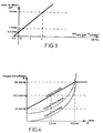
- FIG. 2 illustrates the configuration as a function of the difference ⁇ P between the set pressure and the static or inter-cavity pressure (expressed in mm Hg), the corresponding flow jump ⁇ D 'being expressed in l / min.
- Figure 3 illustrates the configuration as a function of the deviation ⁇ (P setpoint - P intracavitary) expressing the ability to compensate for leaks, in the same system of units.
- the insufflation pressure measured downstream of the pneumatic assembly as indicated above, is preferably voluntarily limited to a maximum threshold so reduce the risk of cardiovascular events for the patient.
- this threshold called also safety pressure
- the safety pressure is modulated according to the debit.
- the safety pressure is modulated according to a function increasing linear flow, up to a value particular flow rate, and above this value of flow, said safety pressure is constant from so as to set an absolute limit to the pressure insufflation.
- the diagram in Figure 4 illustrates, in the case of an example, such a law of variation of the safety pressure.
- the device operates in a cyclic mode (cycle from 2 to 3 seconds for example), all parameters such as defined above being recalculated for each cycle. After each rest phase, the device restarts at the rate minimal.
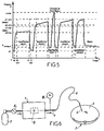
- Figure 5 is a pressure diagram during a flow increase cycle, illustrating the times successive insufflation with separate flows, until the set pressure is reached, a insufflation shutdown being carried out at an instant intermediate where the safety pressure pmax is reached.
- Figure 6 is a block diagram showing a medical resuscitator and its environment
- Figure 7 is a block diagram of the medical insufflator according to the present invention.
- Figure 8 is a detail view, in section, of a particular embodiment of the capillary duct to which is associated with the differential pressure sensor.
- the medical insufflator designated overall by the mark 1 on figure 6, insufflates a gas neutral, such as carbon dioxide CO2, in a cavity operating room 2 of a patient 3.
- a gas neutral such as carbon dioxide CO2
- Gas blowing into the operating cavity 2 is carried out from device 1 by through a circuit comprising an output 4 of gas, a flexible connection tube 5 and a needle Veress 6.
- the gas is kept in reserve, at high pressure (by example 49 bars) and in liquefied form, in a bottle 7 at the outlet of which a regulator is provided primary 8 for reducing the gas pressure to a calibrated and rigorously constant low pressure, by example of three bars.
- a differential pressure sensor 17 is associated with the relaxation capillary.
- Another sensor pressure 18, placed on outlet 4 to the circuit insufflation allows to determine the insufflation pressure Pi by direct measurement.
- the intracavitary pressure Pa is deduced, by calculation, from the measurement of the insufflation pressure Pi and the evaluation of the pressure drop in the insufflation circuit.
- the capillary of trigger 11 made from two cylindrical elements 19 and 20, arranged coaxially one inside the other.
- the first cylindrical element 19, or external element has a gas inlet 21 at one end, and there contains the filter 9.
- the second cylindrical element 20, or inner element carries the valve in its center entry security 10. Between the two cylindrical elements 19 and 20 extends an annular space, the thickness of which (measured radially) is for example 0.16 mm, and which constitutes the capillary duct 11.
- the gas outlet takes place laterally at 22, through a hole drilled in the wall of the first cylindrical element 19, downstream of the capillary duct 11 of annular section.
- the differential pressure sensor 17 uses a first lateral pressure tap 23, in the form of a hole drilled in the wall of the first cylindrical element 19 upstream of the capillary duct 11 of annular section, and a second lateral pressure tap 24, under the form of another hole drilled in the wall of the first cylindrical element 19 downstream of the capillary duct 11.
- the two pressure sensors 17 and 18 are connected to an electronic measurement and control unit 25, which controls the flow control valve 13 according to the enslavement procedures described above, in particular to maintain the intracavitary pressure Pa at the value setpoint, while limiting the blowing pressure Pi at the desired safety threshold value.
- a non-return valve 26 equipping the departure of the insufflation circuit avoids any pollution of the device by rising liquids or fumes, while the compensation of overpressures by suction on the same connecting tube 5 than that intended for insufflation of the gas in the operating cavity 2 is in itself a cause certain of pollution.
- This check valve 26 is associated with a Y connector 27 located at the start of the connection 5, and used to connect a tube bypass 28 with smoke filter 29, ensuring the escape of overpressures to the outside while preventing the rejection of harmful fumes (laser for example) in the atmosphere of the operating room.
- the pneumatic cylinder 31 of the crushing device or pinch of tube 30 can be ordered either automatic in the event of overpressure detection, by via an exhaust solenoid valve 32 controlled by the calculated intracavitary pressure, i.e. manually to allow the evacuation of smoke.
- an exhaust solenoid valve 32 controlled by the calculated intracavitary pressure, i.e. manually to allow the evacuation of smoke.
- no measurement of pressure is not carried out because the sensor 18 could not measure that the exhaust pressure, close to the ambient pressure.
- This device must only act for lasting overpressures; its automatic mode of action is so on the one hand timed, so as not to take into has some sporadic effects due for example to introduction of instruments by the surgeon, and others share limited to equal intracavitary pressures or higher than the set pressure increased by one predetermined value.
- the device which is the subject of the invention also makes it possible to execute a particular cycle of checking the correct implantation of the needle, before insufflation.
- endoscopy practitioners have the habit of injecting, before insufflation, a small volume of air (of the order of 20 cm 3 ) using a syringe through insufflation needle, to make sure that it does not open into a blood vessel or between the sheets of the peritoneum.
- Intra-abdominal pressure is normally a little below ambient atmospheric pressure, the injection of 20 cm 3 of air into a cavity representing more than 10 dm 3 does not cause a significant change in intra-abdominal pressure ; this effect is complemented by the absorption of gas by the entire peritoneal surface. If the needle has not reached the abdominal cavity, if it is implanted between two peritoneal or adherent sheets, or stuck in an intestinal loop, the injection of 20 cm 3 of air will cause a variation in the gas pressure in the cavity where the injection takes place, and the plunger of the syringe will allow some "elastic" re-aspiration.
- this manual test is replaced by a test authorizing or not the activation of the insufflator.
- a particular command of the device automatically triggers the injection of a predetermined and small quantity, for example 20 cm 3 of gas at the minimum flow rate, ie 1 l / min.
- a measurement of the static (intra-abdominal) pressure is carried out before the injection.
- a second measurement is made after this injection. If the two measurements differ by a difference greater than a certain tolerance threshold, the device is put back on hold, and it emits an alarm signal.
- the heating member 12 such that electrical heating resistance, allows not only to keep the gas at constant temperature in the capillary 11 for measuring the gas flow by through the differential pressure sensor 17, but also ensures the heating of this gas (cooled by trigger) to a temperature compatible with that of the body, between 35 ° C and 40 ° C, and preferably between 38 ° C and 40 ° C, before insufflation in the abdominal cavity or other operating cavity.
Description
- maintenir une pression intracavitaire comprise entre 0 et 3300 Pa (0 et 25 mm Hg) ;
- limiter la pression d'insufflation au niveau distal de l'aiguille d'insufflation ou aiguille de Veress en deçà d'un seuil de sécurité (à la connaissance du Déposant, il n'y a jamais eu d'expérimentation clinique réalisée en vue de déterminer ce paramètre ; il semble néanmoins indispensable de rester en deçà de la pression artérielle locale soit 10500 à 13000 Pa, soit 80 à 120 mm Hg) ;
- ne mettre en oeuvre qu'un seul tube de liaison et un seul dispositif trans-péritonéal (aiguilles ou trocard) pour réaliser l'arrivée du gaz, la mesure de la pression intracavitaire et l'évacuation des fumées ou des surpressions intracavitaires ;
- atteindre voire dépasser des débits instantanés de gaz insufflé de 12 litres/minute.
- ils ne comportent pas de dispositif de décharge en cas de surpression intracavitaire ;
- l'injection de gaz froid provoque des troubles métaboliques, amplifiés par l'anesthésie.
- de réaliser et maintenir une pression intracavitaire de référence, dite "pression de consigne", par régulation du débit d'insufflation de gaz avec compensation stricte des fuites hors de la cavité opératoire ;
- de déterminer la pression intracavitaire à partir de la pression d'insufflation et de l'évaluation des pertes de charge ;
- de réaliser une décharge non polluante en cas de surpression intracavitaire ;
- de moduler la pression maximale d'insufflation (seuil de sécurité) en fonction du débit instantané ;
- de réchauffer le gaz insufflé à la température du corps.
- de 0 à t0 : l'insufflateur est au repos. La pression intracavitaire décroít sous l'effet des fuites ou de l'absorption corporelle.
- de t0 à t0+Δt : l'appareil insuffle du gaz sous débit constant. La pression mesurée en tête de circuit augmente très rapidement jusqu'à se stabiliser à p0+Δp (au bout de 80 à 100 millisecondes pour les pressions et les circuits utilisés sur les appareils médicaux). Cette différence de pression Δp correspond à la perte de charge du circuit pour le débit et la configuration du circuit à l'instant t0. Cette perte de charge peut être mémorisée pour la durée du cycle d'insufflation afin de suivre la progression de la pression intracavitaire.
- de t0+Δt à t1 : l'appareil insuffle du gaz sous débit constant. L'écart entre la pression intracavitaire et la pression d'insufflation reste constant et égal à Δp.
- de t1 à t1+Δt1 : l'insufflation est interrompue. La pression Pi mesurée chute très rapidement pour atteindre la pression statique ou intracavitaire.
- de t1+Δt1 à t2 : l'appareil est au repos. La pression Pi mesurée correspond à la pression intracavitaire.
- la mesure de la pression intercavitaire P0 à l'instant initial t0, en l'absence d'insufflation, égale à la pression statique en tête du circuit,
- l'affichage de la pression intercavitaire P0,
- le déclenchement de l'insufflation à l'instant t0 sous un débit restant constant durant le cycle considéré,
- la mesure de la pression d'insufflation Pi à un instant t0+Δt, la durée Δt étant prédéterminée,
- le calcul de la perte de charge Δp du circuit, évaluée comme la différence (Pi-P0) des deux pressions précédemment mesurées,
- la mise en mémoire de la perte de charge Δp spécifique au cycle d'insufflation considéré,
- la mesure de la pression dynamique d'insufflation Pi à un instant t postérieur à l'instant t0+Δt,
- le calcul de la pression intercavitaire Pa à l'instant t, égale à la différence Pi-Δp,
- l'affichage de la pression intercavitaire Pa ainsi déterminée, et sa comparaison avec la valeur de consigne.
- d'un moyen de détente primaire ramenant la pression du gaz à insuffler, à la sortie d'une source de gaz telle que bouteille de stockage de gaz liquéfié, à une basse pression calibrée,
- d'un filtre,
- d'un clapet de sécurité d'entrée,
- d'un capillaire de détente secondaire permettant d'obtenir un régime laminaire, auquel est associé un capteur de pression différentielle pour la détermination du débit gazeux instantané,
- d'une vanne proportionnelle dont l'ouverture est asservie électriquement par comparaison entre le débit instantané et un débit de consigne,
- d'un clapet de sécurité de sortie, et
- d'un circuit de sortie du gaz sur lequel sont disposés les moyens de mesure de la pression d'insufflation, utilisés comme expliqué plus haut pour calculer et réguler la pression intracavitaire.
- P1
- = pression "amont"
- P2
- = pression "aval"
- l
- = longueur du conduit
- Λ
- = coefficient de perte de charge volumique par unité de longueur
- h
- = espace entre les deux parois du conduit
- ρ
- = masse volumique du gaz à température T°
- Vm
- = vitesse moyenne d'écoulement
- Plus l'écart ΔP entre la pression de consigne et la pression intracavitaire sera important, plus le saut de débit entre deux cycles devra être important, ceci afin d'atteindre rapidement la pression de consigne.
- Les sauts de débit seront négatifs si le débit d'insufflation est supérieur aux fuites, c'est-à-dire si δ est négatif ; ils seront positifs si δ est positif.
- Le débit devra être légèrement supérieur à la fuite de gaz constatée en fonctionnement stabilisé.
- Il ne doit pas y avoir dépassement de la pression maximale d'insufflation (voir ci-dessous).
- Le débit doit pouvoir être, si nécessaire, limité à un débit maximum de consigne (par exemple 1l/min en début d'intervention), noté ci-après D consigne.
- d'un filtre 9, par exemple d'une porosité de 5 µ,
- d'un clapet de sécurité d'entrée 10, taré par exemple à une pression de 3,5 bars,
- d'un capillaire de détente 11, maintenu à une température constante par un organe de chauffage 12, et permettant d'obtenir un régime laminaire,
- d'une vanne motorisée de régulation de débit 13, à action proportionnelle, comprenant un gicleur 14 actionné par un moteur 15, dont l'ouverture est asservie électroniquement,
- d'un clapet de sécurité de sortie 16, taré par exemple à une pression de 0,2 bar,
- de la sortie 4 vers le circuit d'insufflation du gaz dans la cavité opératoire 2.
Claims (10)
- Insufflateur médical (1) à régulation automatique de débit gazeux, pour endoscopie diagnostique et chirurgicale, comprenant un circuit d'insufflation (4, 5, 6) d'un gaz neutre dans une cavité opératoire (2), en relation avec une source de gaz neutre sous pression (7), sur ce circuit une vanne pilotée de régulation de débit (13), et des moyens de mesure (18) de la pression d'insufflation (Pi) en tête du circuit d'insufflation (4,5,6), caractérisé en ce qu'il comprend des moyens (25) pour calculer en permanence la pression intercavitaire (Pa) à partir de la pression d'insufflation (Pi), ceci par l'intermédiaire d'une évaluation de la perte de charge (Δp) du circuit, des moyens de comparaison entre la pression intracavitaire (Pa) calculée et une valeur de consigne de cette pression intracavitaire, et des moyens de pilotage de la vanne de régulation de débit (13) en fonction du résultat de la comparaison avec la valeur de consigne précitée, afin de fournir en permanence un débit de gaz neutre (D) minimal pour compenser strictement les fuites de gaz hors de la cavité opératoire (2).
- Insufflateur médical à régulation automatique de débit gazeux selon la revendication 1, caractérisé en ce que ses moyens électroniques (25), pilotés par une horloge pour un fonctionnement cyclique, sont prévus pour assurer successivement, à chaque cycle :la mesure de la pression intercavitaire (P0) à un instant initial (t0), en l'absence d'insufflation, égale à la pression statique en tête du circuit d'insufflation (4,5,6),l'affichage de la pression intercavitaire (P0),le déclenchement de l'insufflation à l'instant (t0) sous un débit (D) restant constant durant le cycle considéré,la mesure de la pression d'insufflation (Pi) à un instant (t0+Δt), la durée (Δt) étant prédéterminée,le calcul de la perte de charge (Δp) du circuit, évaluée comme la différence (Pi-P0) des deux pressions précédemment mesurées,la mise en mémoire de la perte de charge (Δp) spécifique au cycle d'insufflation considéré,la mesure de la pression dynamique d'insufflation (Pi) à un instant (t) postérieur à l'instant (t0+Δt),le calcul de la pression intercavitaire (Pa) à l'instant (t), égale à la différence (Pi-Δp),l'affichage de la pression intercavitaire (Pa) ainsi déterminée, et sa comparaison avec la valeur de consigne.
- Insufflateur médical à régulation automatique de débit selon la revendication 2, caractérisé en ce qu'il comporte un moyen d'évaluation de l'aptitude de l'appareil à compenser les fuites hors de la cavité opératoire (2), par la dérivée (δ) par rapport au temps (t) de l'écart (ΔP) entre la pression de consigne et la pression intracavitaire (Pa).
- Insufflateur médical à régulation automatique de débit gazeux selon l'une quelconque des revendications 1 à 3, caractérisé en ce qu'il comprend un ensemble de régulation pneumatique qui se compose en combinaison, d'amont en aval :d'un moyen de détente primaire (8) ramenant la pression du gaz à insuffler, à la sortie d'une source de gaz telle que bouteille de stockage de gaz liquéfié (7), à une basse pression calibrée,d'un filtre (9),d'un clapet de sécurité d'entrée (10),d'un capillaire de détente secondaire (11) permettant d'obtenir un régime laminaire, auquel est associé un capteur de pression différentielle (17) pour la détermination du débit gazeux instantané (D),d'une vanne proportionnelle (13) dont l'ouverture est aservie électriquement par comparaison entre le débit instantané (D) et un débit de consigne (Dconsigne),d'un clapet de sécurité de sortie (16), etd'un circuit de sortie du gaz (4) sur lequel sont disposés les moyens de mesure (18) de la pression d'insufflation (Pi), utilisés pour calculer et réguler la pression intracavitaire (Pa).
- Insufflateur médical à régulation automatique de débit gazeux selon la revendication 4, caractérisé en ce que l'ensemble de régulation pneumatique est complété par des moyens de maintien en température (12), assurant notamment le réchauffage du gaz parcourant le capillaire (11).
- Insufflateur médical à régulation automatique de débit gazeux selon la revendication 4 ou 5, caractérisé en ce que le sous-ensemble comprenant le capillaire de détente (11) et le capteur différentiel de pression (17) est constitué à partir des deux éléments cylindriques (19,20) coaxiaux, montés l'un dans l'autre, le capillaire (11) étant constitué par un espace libre de section annulaire compris entre les deux éléments cylindriques (19,20), tandis que deux prises de pression (23,24) sont prévues dans l'élément cylindrique extérieur (19), respectivement en amont et en aval de la zone formant capillaire (11), pour alimenter le capteur différentiel de pression (17) à partir duquel est déterminé le débit instantané de gaz (D).
- Insufflateur médical à régulation automatique de débit gazeux selon la revendication 6, caractérisé en ce que le clapet de sécurité d'entrée (10) est incorporé au sous-ensemble précité comprenant le capillaire de détente (11), notamment au centre de l'élément cylindrique intérieur (20).
- Insufflateur médical à régulation automatique de débit gazeux selon l'une quelconque des revendications 1 à 7, caractérisé en ce qu'il comprend des moyens de définition et de modulation d'un seuil maximum de la pression d'insufflation (Pi), dit "pression de sécurité", notamment suivant une fonction linéaire croissante du débit gazeux (D), toutefois avec maintien de cette pression de sécurité à une valeur constante pour les débits se situant au-dessus d'une valeur particulière de débit, l'insufflation étant arrêtée notamment dans un cycle de progression des débits lorsque la pression d'insufflation (Pi) dépasse ladite pression de sécurité.
- Insufflateur médical à régulation automatique de débit gazeux selon l'une quelconque des revendications 1 à 8, caractérisé en ce que le départ du circuit d'insufflation (4,5,6) est équipé d'un clapet antiretour (26), auquel est associé un raccord en Y (27) pour le branchement d'un tube de dérivation (28) avec filtre à fumées (29), assurant l'échappement vers l'extérieur des surpressions intracavitaires, un dispositif du genre vanne (30), tel qu'à écrasement ou pincement de tube assurant le contrôle de l'aspiration et de l'échappement par le tube (28), de façon automatique ou manuelle, la mesure de pression étant neutralisée durant l'ouverture dudit dispositif (30).
- Insufflateur médical à régulation automatique de débit selon l'une quelconque des revendications 1 à 9, caractérisé en ce qu'il est prévu pour exécuter, outre le processus d'insufflation avec régulation du débit, un cycle particulier de contrôle avant insufflation, avec injection automatique d'une quantité prédéterminée et faible de gaz à un débit minimum, et mesures de pressions avant et après cette injection de gaz.
Applications Claiming Priority (3)
| Application Number | Priority Date | Filing Date | Title |
|---|---|---|---|
| FR9402483A FR2716627B1 (fr) | 1994-02-25 | 1994-02-25 | Insufflateur médical à régulation automatique de débit gazeux. |
| FR9402483 | 1994-02-25 | ||
| PCT/FR1995/000218 WO1995023006A1 (fr) | 1994-02-25 | 1995-02-23 | Insufflateur medical a regulation automatique de debit gazeux |
Publications (2)
| Publication Number | Publication Date |
|---|---|
| EP0699083A1 EP0699083A1 (fr) | 1996-03-06 |
| EP0699083B1 true EP0699083B1 (fr) | 1999-10-27 |
Family
ID=9460663
Family Applications (1)
| Application Number | Title | Priority Date | Filing Date |
|---|---|---|---|
| EP95910593A Expired - Lifetime EP0699083B1 (fr) | 1994-02-25 | 1995-02-23 | Insufflateur medical a regulation automatique de debit gazeux |
Country Status (10)
| Country | Link |
|---|---|
| US (1) | US5800381A (fr) |
| EP (1) | EP0699083B1 (fr) |
| JP (1) | JPH08509410A (fr) |
| AT (1) | ATE185976T1 (fr) |
| AU (1) | AU1852095A (fr) |
| CA (1) | CA2161342A1 (fr) |
| DE (1) | DE69512976T2 (fr) |
| ES (1) | ES2140664T3 (fr) |
| FR (1) | FR2716627B1 (fr) |
| WO (1) | WO1995023006A1 (fr) |
Families Citing this family (56)
| Publication number | Priority date | Publication date | Assignee | Title |
|---|---|---|---|---|
| DE19510707A1 (de) * | 1995-03-15 | 1996-09-19 | Uwe Dipl Ing Dey | Verfahren und Vorrichtung zur Reinhaltung eines medizinischen Instruments |
| WO1997018848A1 (fr) * | 1995-11-22 | 1997-05-29 | Storz Endoskop Gmbh | Dispositif pour insuffler du gaz dans une cavite du corps d'un etre humain ou animal |
| SE9700104D0 (sv) * | 1997-01-16 | 1997-01-16 | Astra Ab | Insufflator |
| US6110259A (en) * | 1997-11-21 | 2000-08-29 | Jlj International, Inc. | Smoke evacuation system |
| US6042573A (en) * | 1997-12-11 | 2000-03-28 | Smith & Nephew, Inc. | Surgical valve |
| US6458093B1 (en) * | 1999-02-05 | 2002-10-01 | Storz Endoskop Gmbh | Apparatus for insufflating gas into a corporeal cavity of a human or animal body |
| WO2001035844A2 (fr) | 1999-11-10 | 2001-05-25 | Novacept | Systeme et procede permettant de detecter des perforations dans une cavite corporelle |
| US6402714B1 (en) | 1999-11-12 | 2002-06-11 | Karl Storz Gmbh & Co., Kg | Apparatus and method for controlling high flow insufflation |
| US6603997B2 (en) | 2001-11-02 | 2003-08-05 | Michael C. Doody | Probe penetration detector and method of operation |
| CA2467969C (fr) | 2001-11-21 | 2009-01-27 | E-Z-Em, Inc. | Dispositif, systeme, materiel ou procede de collecte d'un effluent provenant d'un individu |
| US20030181857A1 (en) * | 2002-03-22 | 2003-09-25 | James Blake | Insufflation device with integral heater control |
| DE10245053A1 (de) * | 2002-09-26 | 2004-06-03 | Pichl, Roland, Dipl.-Ing. (FH) | Vorrichtung und Verfahren zum Überprüfen von Endoskopkanälen auf Durchgängigkeit |
| WO2004039415A2 (fr) | 2002-10-28 | 2004-05-13 | Northgate Technologies Inc. | Tube insufflateur a double capacite |
| US7608114B2 (en) | 2002-12-02 | 2009-10-27 | Gi Dynamics, Inc. | Bariatric sleeve |
| US7122058B2 (en) | 2002-12-02 | 2006-10-17 | Gi Dynamics, Inc. | Anti-obesity devices |
| US7182752B2 (en) * | 2003-04-08 | 2007-02-27 | Surgiquest, Incorporated | Continuous gas flow trocar assembly |
| US7285112B2 (en) * | 2003-04-08 | 2007-10-23 | Surgiquest, Incorporated | Gas flow trocar arrangement |
| US7854724B2 (en) * | 2003-04-08 | 2010-12-21 | Surgiquest, Inc. | Trocar assembly with pneumatic sealing |
| US7338473B2 (en) * | 2003-04-08 | 2008-03-04 | Surgiquest, Incorporated | Pneumoseal trocar arrangement |
| US7654975B2 (en) * | 2003-04-24 | 2010-02-02 | Northgate Technologies, Inc. | Mixed-gas insufflation system |
| DE602004024808D1 (de) * | 2003-10-07 | 2010-02-04 | Northgate Technologies Inc | System für die abgabe einer substanz in eine körperhöhle |
| DE602004031034D1 (de) | 2003-10-31 | 2011-02-24 | Trudell Medical Int | System zur manipulierung eines katheters für die ablage einer substanz in einer körperhöhle |
| AU2004305450B2 (en) | 2003-12-09 | 2009-01-08 | Gi Dynamics, Inc. | Intestinal sleeve |
| JP4856067B2 (ja) * | 2004-07-09 | 2012-01-18 | ジーアイ・ダイナミックス・インコーポレーテッド | 胃腸内スリーブを配置するための方法および装置 |
| JP4716689B2 (ja) * | 2004-08-04 | 2011-07-06 | オリンパス株式会社 | 内視鏡システム |
| US7335159B2 (en) * | 2004-08-26 | 2008-02-26 | Scimed Life Systems, Inc. | Endoscope having auto-insufflation and exsufflation |
| US7806850B2 (en) * | 2005-10-24 | 2010-10-05 | Bracco Diagnostics Inc. | Insufflating system, method, and computer program product for controlling the supply of a distending media to an endoscopic device |
| US20070181157A1 (en) * | 2006-02-07 | 2007-08-09 | Dadourian Daniel G | Apparatus and methods for flushing medical devices |
| US20070249990A1 (en) * | 2006-04-20 | 2007-10-25 | Ioan Cosmescu | Automatic smoke evacuator and insufflation system for surgical procedures |
| US7551078B2 (en) * | 2006-05-08 | 2009-06-23 | Ihc Intellectual Asset Management, Llc | Device alert system and method |
| US8663271B2 (en) | 2006-08-04 | 2014-03-04 | Northgate Technologies, Inc. | In-dwelling port for access into a body |
| US8715219B2 (en) | 2008-10-10 | 2014-05-06 | Surgiquest, Inc. | System and method for improved gas recirculation in surgical trocars with pneumatic sealing |
| FR2908048B1 (fr) * | 2006-11-08 | 2009-02-06 | Sopro Sa | Dispositif d'insufflation de gaz permettant une utilisation optimale et securitaire des recipients de gaz sous pression |
| WO2008073916A2 (fr) * | 2006-12-12 | 2008-06-19 | Cytyc Corporation | Procédé et appareil de vérification d'occlusion des trompes de fallope |
| US20080221590A1 (en) * | 2007-03-05 | 2008-09-11 | Intuitive Surgical, Inc. | Apparatus for positioning and holding in place a manually manipulated medical device during the performance of a robotically assisted medical procedure |
| US8419763B2 (en) * | 2007-09-13 | 2013-04-16 | Pivot Medical, Inc. | Safety needle for accessing the interior of a hip joint |
| EP2848192B1 (fr) | 2007-10-15 | 2022-01-19 | University of Maryland, Baltimore | Appareil destiné à étudier les intestins d'un patient |
| US10076612B2 (en) | 2011-10-13 | 2018-09-18 | Lexion Medical Llc | Gas conditioning devices |
| US8066026B2 (en) * | 2008-05-08 | 2011-11-29 | Tyco Values & Controls LP | Diaphragm controlled bypass valve |
| US8028712B2 (en) * | 2008-05-08 | 2011-10-04 | Tyco Valves & Controls Lp | Diaphragm controlled bypass valve |
| CN102264309B (zh) | 2008-10-10 | 2014-01-29 | 瑟吉奎斯特有限公司 | 具有固定装置的低矮轮廓式外科进入装置 |
| US9205207B2 (en) * | 2010-01-15 | 2015-12-08 | Xin Ji | Internal dry powder delivery system and method thereof |
| ES2633144T3 (es) | 2010-11-24 | 2017-09-19 | Bracco Diagnostics Inc. | Sistema para proporcionar y controlar el suministro de un medio de dilatación para colonografía por CT |
| WO2012122263A2 (fr) | 2011-03-08 | 2012-09-13 | Surgiquest, Inc. | Ensemble trocart avec étanchéité pneumatique |
| US8840077B2 (en) | 2011-08-24 | 2014-09-23 | Coopersurgical, Inc. | Table-mounted surgical instrument stabilizers |
| WO2013055395A2 (fr) * | 2011-10-13 | 2013-04-18 | Lexion Medical Llc | Dispositif de conditionnement de gaz |
| US9572595B1 (en) | 2014-03-05 | 2017-02-21 | Northgate Technologies Inc. | In-dwelling port for access into a body |
| AU2015302928B2 (en) | 2014-08-15 | 2021-04-08 | Northgate Technologies Inc. | High resolution system and method for controlling high and low insufflation flow rates |
| CN105412975B (zh) | 2014-09-18 | 2019-05-31 | 苏州安德佳生物科技有限公司 | 一种生物相容性止血制品及其制备方法 |
| ES2784727T3 (es) | 2015-09-30 | 2020-09-30 | Applied Med Resources | Sistema de estabilización de insuflación |
| JP7039497B2 (ja) | 2016-07-14 | 2022-03-22 | インテュイティブ サージカル オペレーションズ, インコーポレイテッド | 手術用器具を制御するためのシステム及び方法 |
| DE102016014980A1 (de) | 2016-12-16 | 2018-06-21 | W.O.M. World Of Medicine Gmbh | Medizintechnische Pumpe mit verbesserter Entlüftung |
| CN108498879B (zh) | 2017-02-28 | 2021-12-28 | 苏州安德佳生物科技有限公司 | 黏膜下注射用组合物和试剂组合及其应用 |
| WO2019147659A1 (fr) * | 2018-01-25 | 2019-08-01 | Biogastrex Llc | Système d'insufflation |
| NZ783367A (en) | 2019-06-27 | 2024-02-23 | Boston Scient Scimed Inc | Detection of an endoscope to a fluid management system |
| DE102021002547A1 (de) | 2021-05-17 | 2022-11-17 | W.O.M. World Of Medicine Gmbh | Medizintechnische Pumpe für die Endoskopie |
Family Cites Families (11)
| Publication number | Priority date | Publication date | Assignee | Title |
|---|---|---|---|---|
| DE2451383C3 (de) * | 1974-10-26 | 1979-05-03 | Hans-Joachim Dr.Med. 2000 Hamburg Lindemann | Regler für ein Insufflationsgerät |
| DE7508556U (de) * | 1975-03-14 | 1975-12-04 | Friedhelm M Wiest Kg | Insufflationsgerät |
| FR2326734A1 (fr) * | 1975-10-04 | 1977-04-29 | Wolf Gmbh Richard | Appareil d'insufflation de gaz applicable notamment au remplissage d'une cavite du corps |
| DE3413631A1 (de) * | 1984-04-11 | 1985-10-24 | Semm, Kurt, Prof. Dr.Med., 2300 Kiel | Monofile vorrichtung zum insufflieren von gas |
| DE3718717A1 (de) * | 1987-06-04 | 1988-12-22 | Wolf Gmbh Richard | Geraet zum insufflieren von gas in eine koerperhoehle |
| US5006109A (en) * | 1989-09-12 | 1991-04-09 | Donald D. Douglas | Method and device for controlling pressure, volumetric flow rate and temperature during gas insuffication procedures |
| DE9106790U1 (fr) * | 1991-06-03 | 1992-10-08 | Fuchs, Manfred, 8151 Warngau, De | |
| US5328458A (en) * | 1991-12-03 | 1994-07-12 | Olympus Optical Co., Ltd. | Insufflation apparatus |
| ES2142334T3 (es) * | 1992-05-07 | 2000-04-16 | Cook William A Australia | Aparato de insuflado con gas. |
| AU678367B2 (en) * | 1992-07-07 | 1997-05-29 | 544456 B.C. Ltd. | Apparatus and method for improved insufflation |
| US5439441A (en) * | 1993-10-12 | 1995-08-08 | Snowden-Pencer, Inc. | Surgical insufflation system with improved determination of body cavity pressure |
-
1993
- 1993-02-23 US US08/537,892 patent/US5800381A/en not_active Expired - Lifetime
-
1994
- 1994-02-25 FR FR9402483A patent/FR2716627B1/fr not_active Expired - Fee Related
-
1995
- 1995-02-23 CA CA002161342A patent/CA2161342A1/fr not_active Abandoned
- 1995-02-23 JP JP7522178A patent/JPH08509410A/ja active Pending
- 1995-02-23 WO PCT/FR1995/000218 patent/WO1995023006A1/fr active IP Right Grant
- 1995-02-23 AU AU18520/95A patent/AU1852095A/en not_active Abandoned
- 1995-02-23 ES ES95910593T patent/ES2140664T3/es not_active Expired - Lifetime
- 1995-02-23 EP EP95910593A patent/EP0699083B1/fr not_active Expired - Lifetime
- 1995-02-23 AT AT95910593T patent/ATE185976T1/de active
- 1995-02-23 DE DE69512976T patent/DE69512976T2/de not_active Expired - Lifetime
Also Published As
| Publication number | Publication date |
|---|---|
| FR2716627B1 (fr) | 1996-04-26 |
| ATE185976T1 (de) | 1999-11-15 |
| DE69512976D1 (de) | 1999-12-02 |
| CA2161342A1 (fr) | 1995-08-31 |
| JPH08509410A (ja) | 1996-10-08 |
| AU1852095A (en) | 1995-09-11 |
| WO1995023006A1 (fr) | 1995-08-31 |
| EP0699083A1 (fr) | 1996-03-06 |
| US5800381A (en) | 1998-09-01 |
| FR2716627A1 (fr) | 1995-09-01 |
| DE69512976T2 (de) | 2000-05-18 |
| ES2140664T3 (es) | 2000-03-01 |
Similar Documents
| Publication | Publication Date | Title |
|---|---|---|
| EP0699083B1 (fr) | Insufflateur medical a regulation automatique de debit gazeux | |
| US11957844B2 (en) | Water out alarm | |
| US20230347097A1 (en) | Methods and systems for delivering gas to a patient | |
| US5006109A (en) | Method and device for controlling pressure, volumetric flow rate and temperature during gas insuffication procedures | |
| US7938113B2 (en) | Inline vaporizer | |
| US7889345B2 (en) | Method and system for detecting the level of anesthesia agent in an anesthesia vaporizer | |
| FR2831825A1 (fr) | Procede et dispositif de regulation a dilution pour appareil respiratoire | |
| US4203316A (en) | Device and method for calibrating pulmonary function testing equipment | |
| US10076612B2 (en) | Gas conditioning devices | |
| AU2017232196B2 (en) | Water out alarm | |
| US11229755B2 (en) | Hydration system | |
| WO1999011312A1 (fr) | Vaporisateur d'anesthesie | |
| FR3097771A1 (fr) | Système de distribution de gaz thérapeutique comprenant une soupape de sécurité | |
| EP4209243A1 (fr) | Dispositif de délivrance de no avec système de dosage d'urgence | |
| FR3138773A1 (fr) | Installation de fourniture de gaz comprenant un ventilateur médical et un dispositif de délivrance de NO avec un système de dosage d’urgence | |
| FR3137841A1 (fr) | Dispositif de délivrance de NO avec système de dosage d’urgence | |
| EP4026577A1 (fr) | Installation de fourniture de gaz thérapeutique à un patient avec prise en compte des défauts d'étanchéité au masque | |
| FR3131538A1 (fr) | Dispositif de délivrance de NO avec système de dosage d’urgence | |
| FR3119330A1 (fr) | Appareil de fourniture de gaz thérapeutique à un patient avec contrôle de la pression au masque | |
| WO2013055395A2 (fr) | Dispositif de conditionnement de gaz |
Legal Events
| Date | Code | Title | Description |
|---|---|---|---|
| PUAI | Public reference made under article 153(3) epc to a published international application that has entered the european phase |
Free format text: ORIGINAL CODE: 0009012 |
|
| 17P | Request for examination filed |
Effective date: 19951113 |
|
| AK | Designated contracting states |
Kind code of ref document: A1 Designated state(s): AT BE CH DE ES FR GB IT LI |
|
| GRAG | Despatch of communication of intention to grant |
Free format text: ORIGINAL CODE: EPIDOS AGRA |
|
| 17Q | First examination report despatched |
Effective date: 19990119 |
|
| GRAG | Despatch of communication of intention to grant |
Free format text: ORIGINAL CODE: EPIDOS AGRA |
|
| GRAG | Despatch of communication of intention to grant |
Free format text: ORIGINAL CODE: EPIDOS AGRA |
|
| GRAH | Despatch of communication of intention to grant a patent |
Free format text: ORIGINAL CODE: EPIDOS IGRA |
|
| RAP1 | Party data changed (applicant data changed or rights of an application transferred) |
Owner name: OGNIER, JEAN-FRANCOIS |
|
| GRAH | Despatch of communication of intention to grant a patent |
Free format text: ORIGINAL CODE: EPIDOS IGRA |
|
| GRAA | (expected) grant |
Free format text: ORIGINAL CODE: 0009210 |
|
| AK | Designated contracting states |
Kind code of ref document: B1 Designated state(s): AT BE CH DE ES FR GB IT LI |
|
| PG25 | Lapsed in a contracting state [announced via postgrant information from national office to epo] |
Ref country code: AT Free format text: LAPSE BECAUSE OF FAILURE TO SUBMIT A TRANSLATION OF THE DESCRIPTION OR TO PAY THE FEE WITHIN THE PRESCRIBED TIME-LIMIT Effective date: 19991027 |
|
| REF | Corresponds to: |
Ref document number: 185976 Country of ref document: AT Date of ref document: 19991115 Kind code of ref document: T |
|
| REG | Reference to a national code |
Ref country code: CH Ref legal event code: EP |
|
| REF | Corresponds to: |
Ref document number: 69512976 Country of ref document: DE Date of ref document: 19991202 |
|
| REG | Reference to a national code |
Ref country code: CH Ref legal event code: NV Representative=s name: MICHELI & CIE INGENIEURS-CONSEILS |
|
| ITF | It: translation for a ep patent filed |
Owner name: BARZANO' E ZANARDO MILANO S.P.A. |
|
| REG | Reference to a national code |
Ref country code: ES Ref legal event code: FG2A Ref document number: 2140664 Country of ref document: ES Kind code of ref document: T3 |
|
| GBT | Gb: translation of ep patent filed (gb section 77(6)(a)/1977) |
Effective date: 20000211 |
|
| PLBE | No opposition filed within time limit |
Free format text: ORIGINAL CODE: 0009261 |
|
| STAA | Information on the status of an ep patent application or granted ep patent |
Free format text: STATUS: NO OPPOSITION FILED WITHIN TIME LIMIT |
|
| 26N | No opposition filed | ||
| REG | Reference to a national code |
Ref country code: GB Ref legal event code: IF02 |
|
| REG | Reference to a national code |
Ref country code: FR Ref legal event code: TP |
|
| REG | Reference to a national code |
Ref country code: FR Ref legal event code: ST |
|
| REG | Reference to a national code |
Ref country code: FR Ref legal event code: RN |
|
| REG | Reference to a national code |
Ref country code: FR Ref legal event code: FC |
|
| PGFP | Annual fee paid to national office [announced via postgrant information from national office to epo] |
Ref country code: ES Payment date: 20100223 Year of fee payment: 16 Ref country code: CH Payment date: 20100212 Year of fee payment: 16 |
|
| PGFP | Annual fee paid to national office [announced via postgrant information from national office to epo] |
Ref country code: IT Payment date: 20100227 Year of fee payment: 16 Ref country code: FR Payment date: 20100305 Year of fee payment: 16 |
|
| PGFP | Annual fee paid to national office [announced via postgrant information from national office to epo] |
Ref country code: GB Payment date: 20100205 Year of fee payment: 16 Ref country code: DE Payment date: 20100211 Year of fee payment: 16 |
|
| PGFP | Annual fee paid to national office [announced via postgrant information from national office to epo] |
Ref country code: BE Payment date: 20100326 Year of fee payment: 16 |
|
| BERE | Be: lapsed |
Owner name: *OGNIER JEAN-FRANCOIS Effective date: 20110228 |
|
| REG | Reference to a national code |
Ref country code: CH Ref legal event code: PL |
|
| GBPC | Gb: european patent ceased through non-payment of renewal fee |
Effective date: 20110223 |
|
| PG25 | Lapsed in a contracting state [announced via postgrant information from national office to epo] |
Ref country code: LI Free format text: LAPSE BECAUSE OF NON-PAYMENT OF DUE FEES Effective date: 20110228 Ref country code: CH Free format text: LAPSE BECAUSE OF NON-PAYMENT OF DUE FEES Effective date: 20110228 |
|
| REG | Reference to a national code |
Ref country code: FR Ref legal event code: ST Effective date: 20111102 |
|
| PG25 | Lapsed in a contracting state [announced via postgrant information from national office to epo] |
Ref country code: BE Free format text: LAPSE BECAUSE OF NON-PAYMENT OF DUE FEES Effective date: 20110228 |
|
| PG25 | Lapsed in a contracting state [announced via postgrant information from national office to epo] |
Ref country code: IT Free format text: LAPSE BECAUSE OF NON-PAYMENT OF DUE FEES Effective date: 20110223 |
|
| REG | Reference to a national code |
Ref country code: DE Ref legal event code: R119 Ref document number: 69512976 Country of ref document: DE Effective date: 20110901 |
|
| PG25 | Lapsed in a contracting state [announced via postgrant information from national office to epo] |
Ref country code: FR Free format text: LAPSE BECAUSE OF NON-PAYMENT OF DUE FEES Effective date: 20110228 |
|
| PG25 | Lapsed in a contracting state [announced via postgrant information from national office to epo] |
Ref country code: GB Free format text: LAPSE BECAUSE OF NON-PAYMENT OF DUE FEES Effective date: 20110223 |
|
| REG | Reference to a national code |
Ref country code: ES Ref legal event code: FD2A Effective date: 20120411 |
|
| PG25 | Lapsed in a contracting state [announced via postgrant information from national office to epo] |
Ref country code: ES Free format text: LAPSE BECAUSE OF NON-PAYMENT OF DUE FEES Effective date: 20110224 |
|
| PG25 | Lapsed in a contracting state [announced via postgrant information from national office to epo] |
Ref country code: DE Free format text: LAPSE BECAUSE OF NON-PAYMENT OF DUE FEES Effective date: 20110901 |