EP0697508A2 - Throttle control system in combination with an automated mechanical transmission system - Google Patents
Throttle control system in combination with an automated mechanical transmission system Download PDFInfo
- Publication number
- EP0697508A2 EP0697508A2 EP95305413A EP95305413A EP0697508A2 EP 0697508 A2 EP0697508 A2 EP 0697508A2 EP 95305413 A EP95305413 A EP 95305413A EP 95305413 A EP95305413 A EP 95305413A EP 0697508 A2 EP0697508 A2 EP 0697508A2
- Authority
- EP
- European Patent Office
- Prior art keywords
- engine
- fueling
- value
- optimal
- mechanical transmission
- Prior art date
- Legal status (The legal status is an assumption and is not a legal conclusion. Google has not performed a legal analysis and makes no representation as to the accuracy of the status listed.)
- Withdrawn
Links
Images

Classifications
-
- B—PERFORMING OPERATIONS; TRANSPORTING
- B60—VEHICLES IN GENERAL
- B60W—CONJOINT CONTROL OF VEHICLE SUB-UNITS OF DIFFERENT TYPE OR DIFFERENT FUNCTION; CONTROL SYSTEMS SPECIALLY ADAPTED FOR HYBRID VEHICLES; ROAD VEHICLE DRIVE CONTROL SYSTEMS FOR PURPOSES NOT RELATED TO THE CONTROL OF A PARTICULAR SUB-UNIT
- B60W10/00—Conjoint control of vehicle sub-units of different type or different function
- B60W10/04—Conjoint control of vehicle sub-units of different type or different function including control of propulsion units
- B60W10/06—Conjoint control of vehicle sub-units of different type or different function including control of propulsion units including control of combustion engines
-
- B—PERFORMING OPERATIONS; TRANSPORTING
- B60—VEHICLES IN GENERAL
- B60W—CONJOINT CONTROL OF VEHICLE SUB-UNITS OF DIFFERENT TYPE OR DIFFERENT FUNCTION; CONTROL SYSTEMS SPECIALLY ADAPTED FOR HYBRID VEHICLES; ROAD VEHICLE DRIVE CONTROL SYSTEMS FOR PURPOSES NOT RELATED TO THE CONTROL OF A PARTICULAR SUB-UNIT
- B60W30/00—Purposes of road vehicle drive control systems not related to the control of a particular sub-unit, e.g. of systems using conjoint control of vehicle sub-units, or advanced driver assistance systems for ensuring comfort, stability and safety or drive control systems for propelling or retarding the vehicle
- B60W30/18—Propelling the vehicle
-
- B—PERFORMING OPERATIONS; TRANSPORTING
- B60—VEHICLES IN GENERAL
- B60W—CONJOINT CONTROL OF VEHICLE SUB-UNITS OF DIFFERENT TYPE OR DIFFERENT FUNCTION; CONTROL SYSTEMS SPECIALLY ADAPTED FOR HYBRID VEHICLES; ROAD VEHICLE DRIVE CONTROL SYSTEMS FOR PURPOSES NOT RELATED TO THE CONTROL OF A PARTICULAR SUB-UNIT
- B60W10/00—Conjoint control of vehicle sub-units of different type or different function
- B60W10/04—Conjoint control of vehicle sub-units of different type or different function including control of propulsion units
-
- B—PERFORMING OPERATIONS; TRANSPORTING
- B60—VEHICLES IN GENERAL
- B60W—CONJOINT CONTROL OF VEHICLE SUB-UNITS OF DIFFERENT TYPE OR DIFFERENT FUNCTION; CONTROL SYSTEMS SPECIALLY ADAPTED FOR HYBRID VEHICLES; ROAD VEHICLE DRIVE CONTROL SYSTEMS FOR PURPOSES NOT RELATED TO THE CONTROL OF A PARTICULAR SUB-UNIT
- B60W10/00—Conjoint control of vehicle sub-units of different type or different function
- B60W10/10—Conjoint control of vehicle sub-units of different type or different function including control of change-speed gearings
- B60W10/11—Stepped gearings
-
- B—PERFORMING OPERATIONS; TRANSPORTING
- B60—VEHICLES IN GENERAL
- B60W—CONJOINT CONTROL OF VEHICLE SUB-UNITS OF DIFFERENT TYPE OR DIFFERENT FUNCTION; CONTROL SYSTEMS SPECIALLY ADAPTED FOR HYBRID VEHICLES; ROAD VEHICLE DRIVE CONTROL SYSTEMS FOR PURPOSES NOT RELATED TO THE CONTROL OF A PARTICULAR SUB-UNIT
- B60W30/00—Purposes of road vehicle drive control systems not related to the control of a particular sub-unit, e.g. of systems using conjoint control of vehicle sub-units, or advanced driver assistance systems for ensuring comfort, stability and safety or drive control systems for propelling or retarding the vehicle
- B60W30/18—Propelling the vehicle
- B60W30/1819—Propulsion control with control means using analogue circuits, relays or mechanical links
-
- F—MECHANICAL ENGINEERING; LIGHTING; HEATING; WEAPONS; BLASTING
- F02—COMBUSTION ENGINES; HOT-GAS OR COMBUSTION-PRODUCT ENGINE PLANTS
- F02D—CONTROLLING COMBUSTION ENGINES
- F02D11/00—Arrangements for, or adaptations to, non-automatic engine control initiation means, e.g. operator initiated
- F02D11/06—Arrangements for, or adaptations to, non-automatic engine control initiation means, e.g. operator initiated characterised by non-mechanical control linkages, e.g. fluid control linkages or by control linkages with power drive or assistance
- F02D11/10—Arrangements for, or adaptations to, non-automatic engine control initiation means, e.g. operator initiated characterised by non-mechanical control linkages, e.g. fluid control linkages or by control linkages with power drive or assistance of the electric type
- F02D11/105—Arrangements for, or adaptations to, non-automatic engine control initiation means, e.g. operator initiated characterised by non-mechanical control linkages, e.g. fluid control linkages or by control linkages with power drive or assistance of the electric type characterised by the function converting demand to actuation, e.g. a map indicating relations between an accelerator pedal position and throttle valve opening or target engine torque
-
- F—MECHANICAL ENGINEERING; LIGHTING; HEATING; WEAPONS; BLASTING
- F16—ENGINEERING ELEMENTS AND UNITS; GENERAL MEASURES FOR PRODUCING AND MAINTAINING EFFECTIVE FUNCTIONING OF MACHINES OR INSTALLATIONS; THERMAL INSULATION IN GENERAL
- F16H—GEARING
- F16H63/00—Control outputs from the control unit to change-speed- or reversing-gearings for conveying rotary motion or to other devices than the final output mechanism
- F16H63/40—Control outputs from the control unit to change-speed- or reversing-gearings for conveying rotary motion or to other devices than the final output mechanism comprising signals other than signals for actuating the final output mechanisms
- F16H63/50—Signals to an engine or motor
- F16H63/502—Signals to an engine or motor for smoothing gear shifts
Definitions
- the present invention relates to vehicular automated transmission systems and, in particular, to vehicular automated mechanical transmission systems including a fuel-controlled internal combustion engine connected by a non-positive coupling to a multiple-speed mechanical transmission. More particularly, the present invention relates to control of fueling of the internal combustion engine utilized in vehicular automated mechanical transmission systems.
- the transmission system control supplies fuel to the engine in a predetermined manner, regardless of the operator's positioning of the throttle pedal.
- the engine Upon completion of an operation, the engine will again be fueled as requested by the operator, i.e. , as indicated by throttle pedal position.
- the process by which fueling of the engine is transitioned from a controller-determined amount to an operator-determined amount is called "throttle recovery.”
- fueling generally was returned to the amount requested by the operator in a substantially straight-line manner. This method, especially at the completion of a vehicle launch operation, may result in degraded engine performance and, thus, was not totally satisfactory.
- the drawbacks of the prior art are overcome by providing a throttle recovery method/system wherein an electronic engine controller-generated optimal engine fueling request is sensed and fueling is caused to increasingly approach the engine controller-generated optimal fueling amount.
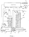
- Figure 1 is a schematic illustration of a vehicular automated mechanical transmission system.
- FIG. 2 is a schematic illustration of a prior art throttle recovery operation.
- FIG. 3 is a schematic illustration of the throttle recovery operation of the present invention.
- FIG. 1 A typical vehicular automated mechanical transmission system of the type disclosed in aforementioned U.S. Pat. No. 4,648,290 is illustrated in Figure 1.
- a driver-operated throttle 24 is sensed at sensor 22 and fed to a central processing unit 38, which also receives inputs relative to engine speed from sensor 28 and/or transmission input shaft speed from sensor 32, transmission output shaft speed from sensor 36, and positive or negative actuations of the driver's gear shift lever, or "joy stick" 1, to be described in greater detail below.
- engine speed is an indication of transmission input shaft speed, and vice versa, especially if clutch 16 is non-slippingly engaged, while transmission output shaft speed is an indication of vehicle speed.
- Control logic circuits, sensors, and actuators for the transmission system 10 may be as disclosed in U.S. Pat. No. 4,361,060.
- central processing unit 38 receives inputs, processes same in accordance with predetermined logic rules, and provides command output signals to pneumatic and/or electrical actuators for control of an exhaust brake 17 and/or an input shaft brake 18 for rapid upshifts, and automatic fuel control 26 to "blip" and "dip” the supply of fuel to the engine 14 to achieve rapid synchronous rotation preparatory to a downshift or upshift, clutch control via operator 30, and ratio shifting via transmission operator 34.
- the central processing unit also sends command output signals to the display 2.
- the semi-automatic transmission system 10 additionally may comprise a usual foot-operated manual clutch control 3 intended for use only for start-from-rest and/or low-speed creeping, maneuvering situations.
- the clutch will be fully automated, as illustrated in aforementioned U.S. Pats. No. 4,081,065; 4,361,060 and/or 5,316,116, and clutch pedal 3 will be eliminated.
- the control 38 may receive signals indicative of manual clutch control 3 position and of actuation of the vehicle brakes 4.
- Engine 14 is electronically controlled and may communicate over an electronic data link conforming to SAE J1922, SAE J 1939 and/or ISO 9141 protocols.
- lever 1 To shift transmission 12, the driver moves lever 1 forward (for upshifts) and rearward (for downshifts) from the position illustrated in Figure 1. It is understood that a single control lever movable forward and backward in a given direction to select a forward and reverse mode of operation, and then movable in a transverse direction to select upshifts and downshifts either single or multiple, of the type disclosed in U.S. Pat. No. 4,442,730, may be substituted for the control lever 1 illustrated.
- the controller 38 will control fueling of the engine according to predetermined logic rules independent of the position of the throttle pedal 24. For example, fueling may be controlled to achieve a selected engine speed and/or engine torque, regardless of throttle pedal position. Upon completion of such operations, fueling control is returned to the operator (i.e ., fuel is supplied in proportion to the displacement of throttle pedal 24) in a throttle recovery operation.
- throttle recovery was done in a substantially straight-line technique (see Figure 2) wherein the fueling of the engine was ramped up at a substantially constant rate from the controller-dictated amount 50 to the operator-requested amount 52. This did not always provide smooth engine performance.
- engine controllers ECU E receive various inputs, including throttle pedal position, and generate an optimal fuel value, 54, which incorporates the particularities of the individual engine and the values of sensed inputs, such as inputs indicative of engine torque values, engine speed, vehicle load, engaged gear ratio and the like.
- an improved throttle recovery operation is achieved by sensing the engine-generated optimal fueling value 54, the current fueling value 56, and commanding fueling such that the difference 58 between the optimal fueling value and the current fueling value is steadily decreased to zero (point 59 on Figure 3).
Abstract
A control method/system for controlling throttle recovery in a vehicular automated transmission system (10) including an electronically cnotrolled engine (14) having an engine controller (ECUE) generating a signal indicative of an optimal engine fueling value (54). During throttle recovery, fueling is commanded to continuously decrease the difference (58) between current engine fueling (56) and the optimal engine fueling value.
Description
- The present invention relates to vehicular automated transmission systems and, in particular, to vehicular automated mechanical transmission systems including a fuel-controlled internal combustion engine connected by a non-positive coupling to a multiple-speed mechanical transmission. More particularly, the present invention relates to control of fueling of the internal combustion engine utilized in vehicular automated mechanical transmission systems.
- Fully and partially automated mechanical transmission systems are well known in the prior art, as may be seen by reference to U.S. Pats. No. 4,081,065; 4,361,060; 4,648,290; 4,850,236; 4,595,986; 5,109,721; 5,157,607 and 5,316,116.
- In such systems, during start-from-stop and/or during gear-change operations, the transmission system control supplies fuel to the engine in a predetermined manner, regardless of the operator's positioning of the throttle pedal. Upon completion of an operation, the engine will again be fueled as requested by the operator, i.e., as indicated by throttle pedal position. The process by which fueling of the engine is transitioned from a controller-determined amount to an operator-determined amount is called "throttle recovery." In the prior art, during the throttle recovery operation, fueling generally was returned to the amount requested by the operator in a substantially straight-line manner. This method, especially at the completion of a vehicle launch operation, may result in degraded engine performance and, thus, was not totally satisfactory.
- In accordance with the present invention, the drawbacks of the prior art are overcome by providing a throttle recovery method/system wherein an electronic engine controller-generated optimal engine fueling request is sensed and fueling is caused to increasingly approach the engine controller-generated optimal fueling amount.
- Accordingly, it is an object of the present invention to provide an improved throttle recovery control method/system for automated mechanical transmission systems equipped with an electronically controlled engine of the type having an engine controller generating a signal indicative of an optimal fueling value for currently sensed conditions.
- This and other objects and advantages of the present invention will become apparent from a reading of the following description of the preferred embodiment taken in connection with the attached drawings.
- Figure 1 is a schematic illustration of a vehicular automated mechanical transmission system.
- Figure 2 is a schematic illustration of a prior art throttle recovery operation.
- Figure 3 is a schematic illustration of the throttle recovery operation of the present invention.
- A typical vehicular automated mechanical transmission system of the type disclosed in aforementioned U.S. Pat. No. 4,648,290 is illustrated in Figure 1. Referring to Figure 1, the position of a driver-operated
throttle 24 is sensed atsensor 22 and fed to acentral processing unit 38, which also receives inputs relative to engine speed from sensor 28 and/or transmission input shaft speed fromsensor 32, transmission output shaft speed fromsensor 36, and positive or negative actuations of the driver's gear shift lever, or "joy stick" 1, to be described in greater detail below. It is understood that engine speed is an indication of transmission input shaft speed, and vice versa, especially ifclutch 16 is non-slippingly engaged, while transmission output shaft speed is an indication of vehicle speed. - Control logic circuits, sensors, and actuators for the
transmission system 10 may be as disclosed in U.S. Pat. No. 4,361,060. Specifically,central processing unit 38 receives inputs, processes same in accordance with predetermined logic rules, and provides command output signals to pneumatic and/or electrical actuators for control of anexhaust brake 17 and/or aninput shaft brake 18 for rapid upshifts, andautomatic fuel control 26 to "blip" and "dip" the supply of fuel to theengine 14 to achieve rapid synchronous rotation preparatory to a downshift or upshift, clutch control via operator 30, and ratio shifting viatransmission operator 34. The central processing unit also sends command output signals to the display 2. Thesemi-automatic transmission system 10 additionally may comprise a usual foot-operated manual clutch control 3 intended for use only for start-from-rest and/or low-speed creeping, maneuvering situations. Preferably, the clutch will be fully automated, as illustrated in aforementioned U.S. Pats. No. 4,081,065; 4,361,060 and/or 5,316,116, and clutch pedal 3 will be eliminated. Thecontrol 38 may receive signals indicative of manual clutch control 3 position and of actuation of the vehicle brakes 4. -
Engine 14 is electronically controlled and may communicate over an electronic data link conforming to SAE J1922, SAE J 1939 and/or ISO 9141 protocols. - To shift
transmission 12, the driver moves lever 1 forward (for upshifts) and rearward (for downshifts) from the position illustrated in Figure 1. It is understood that a single control lever movable forward and backward in a given direction to select a forward and reverse mode of operation, and then movable in a transverse direction to select upshifts and downshifts either single or multiple, of the type disclosed in U.S. Pat. No. 4,442,730, may be substituted for the control lever 1 illustrated. - The structure of a 12-forward-speed, splitter-
type transmission 12, and of the blocked jaw clutch members utilized in the auxiliary transmission section oftransmission 12, is known in the prior art and may be appreciated in greater detail by reference to U.S. Pats. No. 3,799,002; 3,921,469; 3,924,848; 4,194,410; 4,440,037; and to published European Pat. Apps. EP-A-0071353 and EP-A-0117342. - As is well known in such automated transmission systems, to break torque, to cause synchronous conditions and/or to achieve a smooth vehicle launch, at certain times, the
controller 38 will control fueling of the engine according to predetermined logic rules independent of the position of thethrottle pedal 24. For example, fueling may be controlled to achieve a selected engine speed and/or engine torque, regardless of throttle pedal position. Upon completion of such operations, fueling control is returned to the operator (i.e., fuel is supplied in proportion to the displacement of throttle pedal 24) in a throttle recovery operation. In the prior art, throttle recovery was done in a substantially straight-line technique (see Figure 2) wherein the fueling of the engine was ramped up at a substantially constant rate from the controller-dictatedamount 50 to the operator-requestedamount 52. This did not always provide smooth engine performance. - With the advent of electronically controlled engines, engine controllers ECUE receive various inputs, including throttle pedal position, and generate an optimal fuel value, 54, which incorporates the particularities of the individual engine and the values of sensed inputs, such as inputs indicative of engine torque values, engine speed, vehicle load, engaged gear ratio and the like.
- In accordance with the present invention (see Figure 3), an improved throttle recovery operation is achieved by sensing the engine-generated
optimal fueling value 54, thecurrent fueling value 56, and commanding fueling such that thedifference 58 between the optimal fueling value and the current fueling value is steadily decreased to zero (point 59 on Figure 3). - The foregoing has been found to provide a smooth throttle recovery operation without degrading the performance of the
engine 14. - Although the preferred embodiment of the present invention has been described with a certain degree of particularity, various changes to form and detail may be made without departing from the spirit and scope of the invention as hereinafter claimed.
Claims (8)
- A method of controlling a throttle recovery operation in an automated mechanical transmission system (10) comprising an electronically controlled engine (14) having a controller (ECUE) for generating a signal indicative of an optimal engine fueling value (54), a multiple-speed mechanical transmission (12) drivingly connected to the engine by a non-positive coupling and a system controller (38) for receiving inputs and for processing same according to predetermined logic rules to issue command output signals to system actuators, including an actuator (26) for controlling fueling of said engine, said method characterized by:
receiving said signal indicative of optimal engine fueling value; and
during throttle recovery operation, commanding fueling of said engine as a function of said optimal engine fueling value. - The method of claim 1, additionally comprising sensing the value (56) of current fueling of said engine and wherein fueling of said engine is commanded to continuously diminish the difference (58) between said optimal engine fueling value (54) and said current fueling value (56).
- The method of claim 2 wherein said engine is connected to an electronic data link (DL) of the type defined in SAE J1922, SAE J1939 or ISO 9141.
- A system of controlling a throttle recovery operation in an automated mechanical transmission system (10) comprising an electronically controlled engine (14) having a controller (ECUE) for generating a signal indicative of an optimal engine fueling value (54), a multiple-speed mechanical transmission (12) drivingly connected to the engine by a non-positive coupling and a system controller (38) for receiving inputs and for processing same according to predetermined logic rules to issue command output signals to system actuators, including an actuator (26) for controlling fueling of said engine, said system characterized by:
means for receiving said signal indicative of optimal engine fueling value; and
means effective, during throttle recovery operation, for commanding fueling of said engine as a function of said optimal engine fueling value. - The system of claim 4, additionally comprising means for sensing the value (56) of current fueling of said engine and wherein fueling of said engine is commanded to continuously diminish the difference (58) between said optimal engine fueling value (54) and said current fueling value (56).
- The system of claim 5 wherein said engine is connected to an electronic data link (DL) of the type defined in SAE J1922, SAE J1939 or ISO 9141.
- The method of claim 1 wherein said optimal engine fueling value is a function of sensed throttle pedal position.
- The system of claim 4 wherein said optimal engine fueling value is a function of sensed throttle pedal position.
Applications Claiming Priority (2)
| Application Number | Priority Date | Filing Date | Title |
|---|---|---|---|
| GB9416839A GB9416839D0 (en) | 1994-08-19 | 1994-08-19 | Throttle recovery |
| GB9416839 | 1994-08-19 |
Publications (1)
| Publication Number | Publication Date |
|---|---|
| EP0697508A2 true EP0697508A2 (en) | 1996-02-21 |
Family
ID=10760136
Family Applications (1)
| Application Number | Title | Priority Date | Filing Date |
|---|---|---|---|
| EP95305413A Withdrawn EP0697508A2 (en) | 1994-08-19 | 1995-08-02 | Throttle control system in combination with an automated mechanical transmission system |
Country Status (5)
| Country | Link |
|---|---|
| EP (1) | EP0697508A2 (en) |
| JP (1) | JPH0868345A (en) |
| KR (1) | KR960007255A (en) |
| CA (1) | CA2156445A1 (en) |
| GB (1) | GB9416839D0 (en) |
Citations (16)
| Publication number | Priority date | Publication date | Assignee | Title |
|---|---|---|---|---|
| US3799002A (en) | 1972-07-31 | 1974-03-26 | Eaton Corp | Transmission with resiliently loaded main shaft gears |
| US3921469A (en) | 1972-07-31 | 1975-11-25 | Eaton Corp | Transmission with resiliently loaded main shaft gears |
| US3924848A (en) | 1973-06-26 | 1975-12-09 | Fuji Xerox Co Ltd | Paper feed apparatus for gripper-type paper transport device |
| US4081065A (en) | 1976-12-23 | 1978-03-28 | Smyth Robert Ralston | Controlled power clutch |
| US4194410A (en) | 1977-08-05 | 1980-03-25 | Eaton Corporation | Blocked transmission |
| US4361060A (en) | 1978-01-24 | 1982-11-30 | Smyth Robert Ralston | Mechanical automatic transmission |
| EP0071353A2 (en) | 1981-07-27 | 1983-02-09 | Eaton Corporation | Semi-blocked transmission |
| US4440037A (en) | 1981-11-04 | 1984-04-03 | Eaton Corporation | Shift control |
| US4442730A (en) | 1981-08-31 | 1984-04-17 | Twin Disc, Incorporated | Vehicle transmission system and a single lever control device therefor |
| EP0117342A2 (en) | 1982-12-06 | 1984-09-05 | Eaton Corporation | Automatic mechanical transmission system |
| US4595986A (en) | 1984-10-09 | 1986-06-17 | Eaton Corporation | Method for control of automatic mechanical transmission system utilizing a microprocessor based electronic controller |
| US4648290A (en) | 1984-07-23 | 1987-03-10 | Eaton Corporation | Semi-automatic mechanical transmission control |
| US4850236A (en) | 1987-11-20 | 1989-07-25 | Eaton Corporation | Vehicle drive line shift control system and method |
| US5109721A (en) | 1991-05-09 | 1992-05-05 | Eaton Corporation | Range shifting only fault tolerance method/system |
| US5157607A (en) | 1990-01-19 | 1992-10-20 | Eaton Corporation | Control and method for controlling amt system including in-gear fault detection and tolerance |
| US5316116A (en) | 1992-12-09 | 1994-05-31 | Eaton Corporation | Engine control method for use with automatic clutch control |
-
1994
- 1994-08-19 GB GB9416839A patent/GB9416839D0/en active Pending
-
1995
- 1995-08-02 EP EP95305413A patent/EP0697508A2/en not_active Withdrawn
- 1995-08-18 JP JP7233358A patent/JPH0868345A/en active Pending
- 1995-08-18 CA CA002156445A patent/CA2156445A1/en not_active Abandoned
- 1995-08-19 KR KR1019950025542A patent/KR960007255A/en not_active Application Discontinuation
Patent Citations (16)
| Publication number | Priority date | Publication date | Assignee | Title |
|---|---|---|---|---|
| US3799002A (en) | 1972-07-31 | 1974-03-26 | Eaton Corp | Transmission with resiliently loaded main shaft gears |
| US3921469A (en) | 1972-07-31 | 1975-11-25 | Eaton Corp | Transmission with resiliently loaded main shaft gears |
| US3924848A (en) | 1973-06-26 | 1975-12-09 | Fuji Xerox Co Ltd | Paper feed apparatus for gripper-type paper transport device |
| US4081065A (en) | 1976-12-23 | 1978-03-28 | Smyth Robert Ralston | Controlled power clutch |
| US4194410A (en) | 1977-08-05 | 1980-03-25 | Eaton Corporation | Blocked transmission |
| US4361060A (en) | 1978-01-24 | 1982-11-30 | Smyth Robert Ralston | Mechanical automatic transmission |
| EP0071353A2 (en) | 1981-07-27 | 1983-02-09 | Eaton Corporation | Semi-blocked transmission |
| US4442730A (en) | 1981-08-31 | 1984-04-17 | Twin Disc, Incorporated | Vehicle transmission system and a single lever control device therefor |
| US4440037A (en) | 1981-11-04 | 1984-04-03 | Eaton Corporation | Shift control |
| EP0117342A2 (en) | 1982-12-06 | 1984-09-05 | Eaton Corporation | Automatic mechanical transmission system |
| US4648290A (en) | 1984-07-23 | 1987-03-10 | Eaton Corporation | Semi-automatic mechanical transmission control |
| US4595986A (en) | 1984-10-09 | 1986-06-17 | Eaton Corporation | Method for control of automatic mechanical transmission system utilizing a microprocessor based electronic controller |
| US4850236A (en) | 1987-11-20 | 1989-07-25 | Eaton Corporation | Vehicle drive line shift control system and method |
| US5157607A (en) | 1990-01-19 | 1992-10-20 | Eaton Corporation | Control and method for controlling amt system including in-gear fault detection and tolerance |
| US5109721A (en) | 1991-05-09 | 1992-05-05 | Eaton Corporation | Range shifting only fault tolerance method/system |
| US5316116A (en) | 1992-12-09 | 1994-05-31 | Eaton Corporation | Engine control method for use with automatic clutch control |
Also Published As
| Publication number | Publication date |
|---|---|
| GB9416839D0 (en) | 1994-10-12 |
| JPH0868345A (en) | 1996-03-12 |
| CA2156445A1 (en) | 1996-02-20 |
| KR960007255A (en) | 1996-03-22 |
Similar Documents
| Publication | Publication Date | Title |
|---|---|---|
| EP0695893B1 (en) | Continuous selection control for semi-automatic mechanical transmission | |
| EP0731294B1 (en) | Selectable enhanced creep control mode for automated clutch and vehicular automated mechanical transmission system utilizing same | |
| EP0925991B1 (en) | Assisted lever-shifted transmission | |
| US6149545A (en) | Automated transmission upshift control | |
| US5527237A (en) | Control system/method for default start gear ratio selection | |
| EP1020664B1 (en) | Automated transmission downshift control | |
| EP1070625B1 (en) | Starting and driveline shock protection control method and system | |
| EP0911207B1 (en) | Shift control system and method for optimal engine braking | |
| EP0769640B1 (en) | Skip shift selection control system and method | |
| EP1152172B1 (en) | Automated transmission upshift control | |
| EP1070879A1 (en) | Adaptive automated transmission upshift control | |
| US5828974A (en) | Reverse engagement interlock control | |
| EP0697302B1 (en) | Downshift logic for semi-automatic mechanical transmission with manual clutch controller | |
| US5943912A (en) | Control for automated mechanical transmission system | |
| EP0697508A2 (en) | Throttle control system in combination with an automated mechanical transmission system | |
| EP0695890B1 (en) | Adaptive pull-away ratio selection | |
| EP1186808B1 (en) | Shift control method for an automatic transmission |
Legal Events
| Date | Code | Title | Description |
|---|---|---|---|
| PUAI | Public reference made under article 153(3) epc to a published international application that has entered the european phase |
Free format text: ORIGINAL CODE: 0009012 |
|
| AK | Designated contracting states |
Kind code of ref document: A2 Designated state(s): AT DE ES FR GB IT NL SE |
|
| STAA | Information on the status of an ep patent application or granted ep patent |
Free format text: STATUS: THE APPLICATION HAS BEEN WITHDRAWN |
|
| 18W | Application withdrawn |
Withdrawal date: 19970425 |