EP0697199A1 - Bipolar surgical instrument - Google Patents
Bipolar surgical instrument Download PDFInfo
- Publication number
- EP0697199A1 EP0697199A1 EP95111621A EP95111621A EP0697199A1 EP 0697199 A1 EP0697199 A1 EP 0697199A1 EP 95111621 A EP95111621 A EP 95111621A EP 95111621 A EP95111621 A EP 95111621A EP 0697199 A1 EP0697199 A1 EP 0697199A1
- Authority
- EP
- European Patent Office
- Prior art keywords
- electrode
- instrument according
- rod
- bipolar instrument
- surgical bipolar
- Prior art date
- Legal status (The legal status is an assumption and is not a legal conclusion. Google has not performed a legal analysis and makes no representation as to the accuracy of the status listed.)
- Granted
Links
Images


Classifications
-
- A—HUMAN NECESSITIES
- A61—MEDICAL OR VETERINARY SCIENCE; HYGIENE
- A61B—DIAGNOSIS; SURGERY; IDENTIFICATION
- A61B18/00—Surgical instruments, devices or methods for transferring non-mechanical forms of energy to or from the body
- A61B18/04—Surgical instruments, devices or methods for transferring non-mechanical forms of energy to or from the body by heating
- A61B18/12—Surgical instruments, devices or methods for transferring non-mechanical forms of energy to or from the body by heating by passing a current through the tissue to be heated, e.g. high-frequency current
- A61B18/14—Probes or electrodes therefor
- A61B18/1482—Probes or electrodes therefor having a long rigid shaft for accessing the inner body transcutaneously in minimal invasive surgery, e.g. laparoscopy
-
- A—HUMAN NECESSITIES
- A61—MEDICAL OR VETERINARY SCIENCE; HYGIENE
- A61B—DIAGNOSIS; SURGERY; IDENTIFICATION
- A61B18/00—Surgical instruments, devices or methods for transferring non-mechanical forms of energy to or from the body
- A61B18/04—Surgical instruments, devices or methods for transferring non-mechanical forms of energy to or from the body by heating
- A61B18/12—Surgical instruments, devices or methods for transferring non-mechanical forms of energy to or from the body by heating by passing a current through the tissue to be heated, e.g. high-frequency current
- A61B18/14—Probes or electrodes therefor
- A61B18/1402—Probes for open surgery
Definitions
- the invention relates to a surgical bipolar instrument with a tubular housing into which an electrode head provided with two electrodes can be detachably inserted, forming an electrical connection between the electrodes and two conductors arranged in the housing.
- Such a surgical bipolar instrument is known, for example, from US Pat. No. 4,043,342.
- This surgical bipolar instrument has a relatively large holder to which a bipolar head can be detachably attached. This relatively large size also makes it possible to provide a detachable plug connection in which a plurality of plugs are arranged next to one another.
- one conductor is formed by a conductive tubular shaft which is electrically insulated on the outside and the other by a rod which is electrically insulated in the tubular shaft and that an electrode is attached when the electrode head is fully inserted
- the inside of the tubular shaft is electrically conductive, resiliently movable in the radial direction, engages with a projection in a recess of the inner wall of the tubular shaft or the rod and thereby fixes the electrode against axial displacement in the tubular housing, that the tubular shaft and rod between a locking position and a release position in the longitudinal direction can be displaced relative to one another, the tubular shaft and rod in the locking position engaging the insertion elements with the projection in the recess radially immovable between them, while in the release position they allow the projection to radially emerge from the recess, and that the rod in the locking position is in electrical contact with the other electrode.
- the configuration described makes it possible not only to achieve a space-saving construction of the instrument with a few parts, but also to provide a releasable and lockable connection between the electrode head and the housing.
- a major advantage of the construction is that the electrode head is not inserted into the housing in a releasable and thus releasable manner, as in the prior art, but rather that it is locked in the inserted position, so that there is no risk of complicated operations, that the electrode head could loosen or even be detached from the housing.
- the insertion elements are designed as resilient tongues or clamping jaws resting against the tubular shaft in the circumferential direction.
- the rod can have an electrical insulating jacket on the outside, preferably for example a shrink tube made of electrically insulating plastic material.
- the rod has a section with a larger outer diameter which, in the locking position, the insertion elements are radially immovable against the tubular shaft.
- This section forms a locking body inside the tubular shaft, which immovably fixes the plug-in elements with respect to the inner wall of the tubular shaft and which allows the radial movement of the plug-in elements when the rod is displaced relative to the tubular shaft, so that the projections of the plug-in elements emerge from the corresponding recesses and into axial direction can be shifted.
- the section with a larger outside diameter is formed on the rod by a plug-on part made of electrically insulating material. This is attached to the end of the rod, surrounds it in this area in an electrically insulating manner and at the same time performs the function of the locking body.
- the electrode head has a sleeve made of electrically insulating material, into which a contact part of the other electrode and the rod on the other side are immersed.
- This sleeve thus forms a connection and guide sleeve in which the rod and the other electrode meet and establish an electrical connection there, this area being electrically insulated from the outside.
- this sleeve can consist of ceramic.
- the sleeve is inserted into a carrier made of metal, which comprises the one electrode, the insertion element and a connection between the electrode and insertion elements.
- a carrier made of metal which comprises the one electrode, the insertion element and a connection between the electrode and insertion elements.
- the electrode head has only a very few parts, namely the carrier, the other electrode insulated therein and the sleeve for establishing the connection between the rod and the other electrode.
- the carrier comprises a recess, which is open on one side and extends essentially over the length of the one electrode, for receiving an insulating body, in which the second electrode is embedded in a protruding line.
- the carrier forms a large-area electrode with a U-shaped cross section, into which the insulating body is inserted.
- This receives the second, cutting-shaped electrode, which protrudes linearly over the insulating body and thus forms a linear electrode, which has a substantially smaller area than the flat electrode formed by the carrier.
- the second electrode runs along a line which has at least two differently directed sections, and that the insulating body is designed to run parallel to this line. This makes it possible to implement very different configurations of the linear electrode, which is adapted to the respective purposes. Due to the easy interchangeability of the electrode heads, it is possible at any time to use electrodes with lines that are particularly suitable for the specific application.
- the two sections are, for example, rectilinear and run from a highest point at their ends to a common lowest point. This gives a kinked line with a deepest point approximately in the central area, so that vessels can be located in this area, for example.
- a section falling towards the free end of the electrode head adjoins a highest point of the line and merges into a section which rises in the form of a hook.
- a flow channel which is in flow connection with a longitudinal channel escaping into the surroundings in the electrode head. This makes it possible to bring a flushing or cooling liquid through this flow channel up to the electrode head and then to dispense this liquid through the longitudinal channel into the surroundings of the electrode head, in order to achieve cooling and flushing.
- the longitudinal channel is formed by grooves lying one on top of the other in two parts of the electrode head, in particular the two parts can be the one electrode and an insulating body surrounding the other electrode.
- the flow channel is formed by the annular space between the tubular shaft and the rod; in another embodiment it can also be provided that the flow channel runs inside the rod.
- the surgical bipolar instrument shown in the drawing comprises an elongated, cylindrical tubular shaft 1 made of metal, the outside of which is electrically insulated from the outside by an insulating jacket 2.
- the insulating jacket 2 can be, for example, a plastic hose shrunk onto the tubular shaft.
- a rod 3 made of metal is arranged centrally and at a distance from the tubular shaft 1, which rod is mounted centrally and longitudinally displaceably in the tubular shaft 1 by means not shown.
- tubular shaft 1 can be rigidly connected to a handle branch on which a second handle branch is pivotally articulated, which acts on the rod 3 via an articulated connection, so that when the branches pivot against one another the rod 3 is moved longitudinally in the tubular shaft.
- a handle branch on which a second handle branch is pivotally articulated which acts on the rod 3 via an articulated connection, so that when the branches pivot against one another the rod 3 is moved longitudinally in the tubular shaft.
- Other mechanisms of longitudinal displacement are of course also possible.
- the tubular shaft 1 and the rod 3 together form a housing of a surgical bipolar instrument, which carries at its free end an electrode head 4 which can be detachably connected to the tubular shaft 1.
- This electrode head 4 comprises a metallic carrier 8, the is in turn divided into a first electrode 5, an insertion section 6 and a connecting part 7 connecting the electrode to the insertion section.
- the first electrode 5 is U-shaped in cross section and has a trough-shaped receptacle 11 for an insulating body 12, which runs between two parallel side walls 9, 10 and is inserted into the receptacle 11 and fills it completely.
- the insulating body can consist, for example, of ceramic, in which a cutting edge-shaped second electrode 13 running parallel to the side walls 9, 10 is arranged centrally between the side walls 9 and 10 such that the upper edge 14 of the electrode 13 protrudes slightly above the insulating body 12 in a linear manner .
- the side walls 9, 10 are designed to fall in a straight line from the rear end of the first electrode 5 to its free end; the insulating body 12 and the upper edge 14 of the second electrode 13 assume the same contour.
- the cylindrical connecting part 7 which has a continuous bore 15 into which an insulating sleeve 16 made of ceramic, lining the bore 15, is inserted. This passes through the connecting part 7 over its entire length.
- the extension part 7 is joined together by the plug-in elements 19 which form the plug-in section and which arise from the sleeve-shaped part of the carrier which adjoins the connecting part 7 through longitudinal slots 20.
- These insertion elements 19 are designed to be radially resilient through the longitudinal slots 20, as is the case with collets or spring tongues. At their free end, they carry an outwardly projecting annular bead 21.
- the electrode head 4 described above can be releasably attached to the housing consisting of tubular shaft 1 and rod 3.
- the housing consisting of tubular shaft 1 and rod 3.
- the insertion elements 19 then lie flat against the inside 22 and establish electrical contact between the carrier 8 on the one hand and the tubular shaft 1 on the other.
- This tubular shaft 1 lies in a step 24 of the extension part 7, so that the extension part 7 and the insulating jacket 2 are flush.
- the rod 3 carries in its transition region to the pin-shaped end 18 a plug-on part 25 made of electrically insulating plastic material, which surrounds an insulating jacket 26 in the form of a shrunk-on plastic tube surrounding the rod 3 and which is located on the pin-shaped end 18 extends to a metal ring 27 fixed thereon, which ends flush with the plug-on part 25.
- the plug-on part 25 has a region 28 with a larger outer diameter, this region forms a locking body which, with the relative positioning of the rod 3 and the tubular shaft 1, presses the plug-in elements 19 radially outward and thereby fixes the annular bead 21 in the circumferential groove 23.
- the insertion elements 19 can no longer move in the radial direction, so that the annular bead 21 at the same time also fixes the electrode head 4 in the axial direction due to the engagement in the circumferential groove 23.
- the pin-shaped end 18 of the rod 3 dips into the insulating sleeve 16 and creates an electrical connection between the rod 3 on the one hand and the second electrode 13 on the other hand by contact with the contact pin 17.
- either the tubular shaft 1 or the rod 3 In order to be able to release the locking of the electrode head, either the tubular shaft 1 or the rod 3 must be moved so far to the rear that the area 28 no longer impedes radial movement of the insertion elements 19, so that the insertion elements 19 can be resiliently bent inwards .
- the annular bead 21 can then emerge from the circumferential groove 23, and an axial separation of the electrode head 4 from the tubular shaft and rod is possible.
- the annular bead 21 engages in a circumferential groove 23 in the tubular shaft 1, in principle it would also be possible to provide on the plug-in elements a projection which engages in a recess of the rod and which is prevented by the tubular shaft from axially emerging from the recess.
- the connection of the electrode head to the tubular shaft described here 1 and the rod 3 is based on the principle of a collet, in which the elastic insertion elements can be bent radially in the release position, but not in the locking position. This principle can be implemented in different configurations which are known per se to the person skilled in the art.
- connections between the electrode head 4 on the one hand and the tubular shaft 1 and the rod 3 on the other hand not only cause a mechanical connection of the electrode head 4, but at the same time also the electrical connections between the first electrode 5 and the second electrode 13 with these two parts.
- electrode heads 4 of different configurations are to be used, so that they must be easy to replace.
- the upper edge 14 of the second electrode 13 slopes down in a straight line from the housing end to the free end, as can be seen from the illustration in FIGS. 1 and 2.
- the upper edge 14 runs parallel to the bottom 29 of the receptacle 11, that is to say parallel to the longitudinal axis of the instrument.
- the upper edge 14 is divided into two rectilinear sections 30, 31, which start from a higher point 32 and 33 at the ends of the second electrode descending towards a deepest point 34 arranged between the ends.
- this upper edge has a rectilinear section 30 falling from the rear highest point 32 to a lowest point 34 and an adjoining curved section 31 so that the second electrode takes on the overall shape of a hook.
- a channel 35 which runs in the longitudinal direction and which, together with a channel 36 covering it, forms a closed longitudinal channel 37 in the underside of the insulating body 12 which penetrates the electrode head 4 in the longitudinal direction and which extends at the front end 38 of the electrode head 4 exits.
- This longitudinal channel 37 creates a connection between the ring channel 39 in the housing and the environment, which is delimited on the one hand by the rod 3 with the plug-on part 25 and on the other hand by the tubular shaft 1.
- This ring channel 39 is through the area 28 with an enlarged outer diameter of the plug-on part 25 and separated by the push-in elements 19 pressed against the inside 22 of the tubular shaft 1 into a downstream part 40, which adjoins the electrode head 4, and an upstream part 41.
- Both parts are connected to one another through the longitudinal slots 20 between the insertion elements 19, so that a flushing and cooling liquid can be introduced from the distal end of the tubular shaft 1 to the electrode head 4 through the annular channel 39; this liquid then emerges through the longitudinal channel 37 at the front end 38 of the electrode head 4 and rinses and cools the engagement area of the electrodes.
- the longitudinal channel 37 can also dispense liquid laterally from the electrode head through additional openings (not shown in the drawing), different exit patterns are possible here.
- the flow channel in the interior of the tubular shaft is not formed by the annular channel 39, but that a corresponding flow channel is arranged in the interior of the rod 3, which is in flow connection with the longitudinal channel 37 or with a longitudinal channel in the electrode head, which is guided, for example, by the contact pin 17.
Abstract
Description
Die Erfindung betrifft ein chirurgisches Bipolarinstrument mit einem rohrförmigen Gehäuse, in das ein mit zwei Elektroden versehener Elektrodenkopf unter Ausbildung einer elektrischen Verbindung zwischen den Elektroden und zwei im Gehäuse angeordneten Leitern lösbar einsteckbar ist.The invention relates to a surgical bipolar instrument with a tubular housing into which an electrode head provided with two electrodes can be detachably inserted, forming an electrical connection between the electrodes and two conductors arranged in the housing.
Ein solches chirurgisches Bipolarinstrument ist beispielsweise bekannt aus der US-Patentschrift 4,043,342.Such a surgical bipolar instrument is known, for example, from US Pat. No. 4,043,342.
Dieses chirurgische Bipolarinstrument weist eine relativ große Halterung auf, an der ein Bipolarkopf lösbar befestigt werden kann. Durch diese relativ große Baugröße ist es auch möglich, eine lösbare Steckverbindung vorzusehen, bei der mehrere Stecker nebeneinander angeordnet werden.This surgical bipolar instrument has a relatively large holder to which a bipolar head can be detachably attached. This relatively large size also makes it possible to provide a detachable plug connection in which a plurality of plugs are arranged next to one another.
Dies ist jedoch nicht möglich, wenn ein derartiges chirurgisches Instrument für die mikroinvasive Chirurgie verwendet werden soll, wenn also das Instrument durch Trokare hindurch in den Körper eingeführt werden soll und daher entsprechend raumsparend ausgestaltet werden muß.However, this is not possible if such a surgical instrument is to be used for micro-invasive surgery, ie if the instrument is to be inserted into the body through trocars and therefore has to be designed in a space-saving manner.
Es ist Aufgabe der Erfindung, ein gattungsgemäßes chirurgisches Bipolarinstrument so auszubilden, daß es für den Einsatz in der mikroinvasiven Chirurgie besonders geeignet ist.It is an object of the invention to design a generic surgical bipolar instrument so that it is particularly suitable for use in microinvasive surgery.
Diese Aufgabe wird bei einem chirurgischen Bipolarinstrument der eingangs beschriebenen Art erfindungsgemäß dadurch gelöst, daß ein Leiter durch einen leitenden, außenseitig elektrisch isolierten Rohrschaft und der andere durch einen im Rohrschaft elektrisch isoliert von diesem gelagerten Stab gebildet werden, daß eine Elektrode bei vollständig eingestecktem Elektrodenkopf an der Innenseite des Rohrschafts elektrisch leitend anliegende, federnd in radialer Richtung bewegbare, mit einem Vorsprung in einen Rücksprung der Innenwand des Rohrschafts oder des Stabs eingreifende und die Elektrode dadurch gegen eine axiale Verschiebung im rohrförmigen Gehäuse festlegende Einsteckelemente aufweist, daß Rohrschaft und Stab zwischen einer Verriegelungsposition und einer Freigabeposition in Längsrichtung relativ zueinander verschiebbar sind, wobei Rohrschaft und Stab in der Verriegelungsposition die Einsteckelemente mit dem Vorsprung in den Rücksprung eingreifend radial unverschiebbar zwischen sich einschließen, während sie in der Freigabeposition ein radiales Austreten des Vorsprungs aus dem Rücksprung zulassen, und daß der Stab in der Verriegelungsposition an der anderen Elektrode elektrisch leitend anliegt.This object is achieved according to the invention in a surgical bipolar instrument of the type described in the introduction in that one conductor is formed by a conductive tubular shaft which is electrically insulated on the outside and the other by a rod which is electrically insulated in the tubular shaft and that an electrode is attached when the electrode head is fully inserted the inside of the tubular shaft is electrically conductive, resiliently movable in the radial direction, engages with a projection in a recess of the inner wall of the tubular shaft or the rod and thereby fixes the electrode against axial displacement in the tubular housing, that the tubular shaft and rod between a locking position and a release position in the longitudinal direction can be displaced relative to one another, the tubular shaft and rod in the locking position engaging the insertion elements with the projection in the recess radially immovable between them, while in the release position they allow the projection to radially emerge from the recess, and that the rod in the locking position is in electrical contact with the other electrode.
Durch die beschriebene Ausgestaltung wird es möglich, mit wenigen Teilen nicht nur einen raumsparenden Aufbau des Instruments zu erreichen, sondern auch eine lösbare und verriegelbare Verbindung zwischen dem Elektrodenkopf und dem Gehäuse vorzusehen.The configuration described makes it possible not only to achieve a space-saving construction of the instrument with a few parts, but also to provide a releasable and lockable connection between the electrode head and the housing.
Dazu werden einem Rohrschaft und einem darin angeordneten Stab zwei getrennte Aufgaben übertragen, nämlich einmal die Aufgabe einer lösbaren Halterung des Elektrodenkopfs nach Art einer Spannzange und zum anderen die elektrische Verbindung der beiden Elektroden des Elektrodenkopfs mit einer am anderen Ende des Instruments angeordneten elektrischen Versorgungseinheit. Ein wesentlicher Vorteil der Konstruktion liegt auch darin, daß der Elektrodenkopf nicht wie beim Stand der Technik nur lösbar und damit verlierbar in das Gehäuse eingesteckt wird, sondern daß eine Verriegelung in der eingesteckten Position erfolgt, so daß auch bei komplizierten Operationen nicht die Gefahr besteht, daß sich der Elektrodenkopf lockern oder gar von dem Gehäuse gelöst werden könnte.For this purpose, two separate tasks are assigned to a tubular shaft and a rod arranged therein, namely the task of releasably holding the electrode head in the manner of a collet and, on the other hand, the electrical connection of the two electrodes of the electrode head to an electrical supply unit arranged at the other end of the instrument. A major advantage of the construction is that the electrode head is not inserted into the housing in a releasable and thus releasable manner, as in the prior art, but rather that it is locked in the inserted position, so that there is no risk of complicated operations, that the electrode head could loosen or even be detached from the housing.
Bei einer bevorzugten Ausführungsform ist vorgesehen, daß die Einsteckelemente als in Umfangsrichtung des Rohrschafts an diesem anliegende federnde Zungen oder Spannbacken ausgebildet sind.In a preferred embodiment it is provided that the insertion elements are designed as resilient tongues or clamping jaws resting against the tubular shaft in the circumferential direction.
Der Stab kann außenseitig einen elektrischen Isoliermantel tragen, vorzugsweise beispielsweise einen Schrumpfschlauch aus elektrisch isolierendem Kunststoffmaterial.The rod can have an electrical insulating jacket on the outside, preferably for example a shrink tube made of electrically insulating plastic material.
Besonders vorteilhaft ist es, wenn der Stab einen Abschnitt mit größerem Außendurchmesser aufweist, der in der Verriegelungsposition die Einsteckelemente radial unverschieblich gegenüber dem Rohrschaft festlegt. Dieser Abschnitt bildet einen Verriegelungskörper im Inneren des Rohrschafts, der die Einsteckelemente gegenüber der Innenwand des Rohrschafts unverschieblich festlegt und der bei Relativverschiebung des Stabs gegenüber dem Rohrschaft die freie radiale Bewegung der Einsteckelemente zuläßt, so daß die Vorsprünge der Einsteckelemente aus den entsprechenden Rücksprüngen austreten und in axialer Richtung verschoben werden können.It is particularly advantageous if the rod has a section with a larger outer diameter which, in the locking position, the insertion elements are radially immovable against the tubular shaft. This section forms a locking body inside the tubular shaft, which immovably fixes the plug-in elements with respect to the inner wall of the tubular shaft and which allows the radial movement of the plug-in elements when the rod is displaced relative to the tubular shaft, so that the projections of the plug-in elements emerge from the corresponding recesses and into axial direction can be shifted.
Besonders vorteilhaft ist es, wenn der Abschnitt mit größerem Außendurchmesser auf dem Stab durch ein Aufsteckteil aus elektrisch isolierendem Material gebildet wird. Dieses wird auf das Ende des Stabs aufgesteckt, umgibt diesen in diesem Bereich elektrisch isolierend und übt gleichzeitig die Funktion des Verriegelungskörpers aus.It is particularly advantageous if the section with a larger outside diameter is formed on the rod by a plug-on part made of electrically insulating material. This is attached to the end of the rod, surrounds it in this area in an electrically insulating manner and at the same time performs the function of the locking body.
Bei einer bevorzugten Ausführungsform ist vorgesehen , daß der Elektrodenkopf eine Hülse aus elektrisch isolierendem Material aufweist, in die einseitig ein Kontaktteil der anderen Elektrode und auf der anderen Seite der Stab eintauchen. Diese Hülse bildet somit eine Verbindungs- und Führungshülse, in der sich der Stab und die andere Elektrode treffen und dort eine elektrische Verbindung herstellen, wobei dieser Bereich nach außen hin elektrisch isoliert ist.In a preferred embodiment it is provided that the electrode head has a sleeve made of electrically insulating material, into which a contact part of the other electrode and the rod on the other side are immersed. This sleeve thus forms a connection and guide sleeve in which the rod and the other electrode meet and establish an electrical connection there, this area being electrically insulated from the outside.
Insbesondere kann diese Hülse aus Keramik bestehen.In particular, this sleeve can consist of ceramic.
Es ist dabei weiterhin vorteilhaft, wenn die Hülse in einen aus Metall bestehenden Träger eingesetzt ist, der die eine Elektrode, das Einsteckelement sowie eine Verbindung zwischen Elektrode und Einsteckelementen umfaßt. Da-mit weist der Elektrodenkopf nur sehr wenige Teile auf, nämlich den Träger, die in diesen isolierend eingesetzte andere Elektrode und die Hülse zur Herstellung der Verbindung zwischen Stab und der anderen Elektrode.It is furthermore advantageous if the sleeve is inserted into a carrier made of metal, which comprises the one electrode, the insertion element and a connection between the electrode and insertion elements. In order to the electrode head has only a very few parts, namely the carrier, the other electrode insulated therein and the sleeve for establishing the connection between the rod and the other electrode.
Bei einer bevorzugten Ausführungsform ist vorgesehen, daß der Träger eine sich im wesentlichen über die Länge der einen Elektrode erstreckende, einseitig offene Ausnehmung zur Aufnahme eines Isolierkörpers umfaßt, in den die zweite Elektrode linienförmig überstehend eingebettet ist. Es ergibt sich dabei eine besonders günstige Konfiguration für die Elektroden, der Träger bildet nämlich eine großflächige, im Querschnitt U-förmige Elektrode aus, in die der Isolierkörper eingesetzt ist. Dieser nimmt seinerseits die zweite, schneidenförmig ausgebildete Elektrode auf, die linienförmig über den Isolierkörper vorsteht und somit eine linienförmige Elektrode bildet, die eine wesentlich kleinere Fläche aufweist als die durch den Träger gebildete flächige Elektrode.In a preferred embodiment it is provided that the carrier comprises a recess, which is open on one side and extends essentially over the length of the one electrode, for receiving an insulating body, in which the second electrode is embedded in a protruding line. This results in a particularly favorable configuration for the electrodes, namely the carrier forms a large-area electrode with a U-shaped cross section, into which the insulating body is inserted. This in turn receives the second, cutting-shaped electrode, which protrudes linearly over the insulating body and thus forms a linear electrode, which has a substantially smaller area than the flat electrode formed by the carrier.
Dabei kann vorgesehen sein, daß die zweite Elektrode längs einer Linie verläuft, die mindestens zwei unterschiedlich gerichtete Abschnitte aufweist, und daß der Isolierkörper parallel zu dieser Linie verlaufend ausgebildet ist. Dadurch ist es möglich, sehr unterschiedliche Konfigurationen der linienförmigen Elektrode zu verwirklichen, die den jeweiligen Einsatzzwecken angepaßt ist. Durch die leichte Auswechselbarkeit der Elektrodenköpfe ist es jederzeit möglich, Elektroden mit für den speziellen Einsatzzweck besonders geeigneter Linienführung zu verwenden.It can be provided that the second electrode runs along a line which has at least two differently directed sections, and that the insulating body is designed to run parallel to this line. This makes it possible to implement very different configurations of the linear electrode, which is adapted to the respective purposes. Due to the easy interchangeability of the electrode heads, it is possible at any time to use electrodes with lines that are particularly suitable for the specific application.
Bei einer ersten Ausführungsform sind die beiden Abschnitte beispielsweise geradlinig ausgebildet und laufen von einem höchsten Punkt an ihren Enden zu einem gemeinsamen tiefsten Punkt. Man erhält damit eine abgeknickte Linie mit einer tiefsten Stelle etwa im Mittelbereich, so daß beispielsweise in diesem Bereich Gefäße lokalisiert werden können.In a first embodiment, the two sections are, for example, rectilinear and run from a highest point at their ends to a common lowest point. This gives a kinked line with a deepest point approximately in the central area, so that vessels can be located in this area, for example.
Bei einer anderen Ausführungsform kann vorgesehen sein, daß sich an einen höchsten Punkt der Linie ein zum freien Ende des Elektrodenkopfs abfallender Abschnitt anschließt, der in einen hakenförmig ansteigenden Abschnitt übergeht. Der Operateur hat damit die Möglichkeit, mit einer solchen Ausgestaltung ein gewünschtes Gewebeteil zu erfassen und gegebenenfalls aus seiner Körperposition zu verlagern, so daß dieses Gewebeteil isoliert geschnitten oder koaguliert werden kann.In another embodiment it can be provided that a section falling towards the free end of the electrode head adjoins a highest point of the line and merges into a section which rises in the form of a hook. The surgeon thus has the possibility of using such a configuration to detect a desired tissue part and, if necessary, to shift it from his body position, so that this tissue part can be cut or coagulated in isolation.
Bei einer weiteren bevorzugten Ausführungsform kann vorgesehen sein, daß im Gehäuse ein dieses in Längsrichtung durchsetzender Strömungskanal angeordnet ist, der mit einem in die Umgebung austretenden Längskanal im Elektrodenkopf in Strömungsverbindung steht. Es wird dadurch möglich, durch diesen Strömungskanal eine Spül- oder Kühlflüssigkeit bis an den Elektrodenkopf heranzuführen und diese Flüssigkeit dann durch den Längskanal in die Umgebung des Elektrodenkopfs abzugeben, um dadurch eine Kühlung und Spülung zu erreichen.In a further preferred embodiment it can be provided that in the housing there is arranged in the longitudinal direction a flow channel which is in flow connection with a longitudinal channel escaping into the surroundings in the electrode head. This makes it possible to bring a flushing or cooling liquid through this flow channel up to the electrode head and then to dispense this liquid through the longitudinal channel into the surroundings of the electrode head, in order to achieve cooling and flushing.
Günstig ist es, wenn der Längskanal am vorderen Ende des Elektrodenkopfs austritt.It is favorable if the longitudinal channel emerges at the front end of the electrode head.
Bei einer speziellen Ausgestaltung ist dabei vorgesehen, daß der Längskanal durch aufeinanderliegende Rinnen in zwei Teilen des Elektrodenkopfs gebildet wird, insbesondere könne die zwei Teile die eine Elektrode und ein die andere Elektrode umgebender Isolierkörper sein.In a special embodiment it is provided that the longitudinal channel is formed by grooves lying one on top of the other in two parts of the electrode head, in particular the two parts can be the one electrode and an insulating body surrounding the other electrode.
Es ist vorteilhaft, wenn der Strömungskanal durch den Ringraum zwischen Rohrschaft und Stab gebildet wird, bei einer anderen Ausführungsform kann auch vorgesehen sein, daß der Strömungskanal im Inneren des Stabs verläuft.It is advantageous if the flow channel is formed by the annular space between the tubular shaft and the rod; in another embodiment it can also be provided that the flow channel runs inside the rod.
Die nachfolgende Beschreibung bevorzugter Ausführungsformen der Erfindung dient im Zusammenhang mit der Zeichnung der näheren Erläuterung. Es zeigen:
- Figur 1:
- eine perspektivische Ansicht der wesentlichen Teile eines bipolaren Rohrschaftinstruments im Bereich des Elektrodenkopfs;
- Figur 2:
- eine Schnittansicht längs Linie 2-2 bei verriegeltem Elektrodenkopf;
- Figur 3:
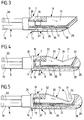
- eine teilweise in Längsrichtung geschnittene Seitenansicht eines bevorzugten Ausführungsbeispiels eines Elektrodenkopfs;
- Figur 4:
- eine Ansicht
ähnlich Figur 3 bei einem anderen Ausführungsbeispiel eines Elektrodenkopfs; - Figur 5:
- eine Ansicht
ähnlich Figur 3 bei einem weiteren bevorzugten Ausführungsbeispiel eines Elektrodenkopfs; - Figur 6:
- eine Draufsicht auf das vordere Ende des Elektrodenkopfs der
Figur 2 in Richtung des Pfeils A inFigur 2 und - Figur 7:
- eine Schnittansicht längs Linie 7-7 in
Figur 2.
- Figure 1:
- a perspective view of the essential parts of a bipolar tubular shaft instrument in the region of the electrode head;
- Figure 2:
- a sectional view taken along line 2-2 with the electrode head locked;
- Figure 3:
- a partially longitudinally sectioned side view of a preferred embodiment of an electrode head;
- Figure 4:
- a view similar to Figure 3 in another embodiment of an electrode head;
- Figure 5:
- a view similar to Figure 3 in a further preferred embodiment of an electrode head;
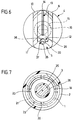
- Figure 6:
- a plan view of the front end of the electrode head of Figure 2 in the direction of arrow A in Figure 2 and
- Figure 7:
- a sectional view taken along line 7-7 in Figure 2.
Das in der Zeichnung dargestellte chirurgische Bipolarinstrument umfaßt einen länglichen, zylindrischen Rohrschaft 1 aus Metall, dessen Außenseite durch einen Isoliermantel 2 nach außen hin elektrisch isoliert ist. Der Isoliermantel 2 kann beispielsweise ein auf den Rohrschaft aufgeschrumpfter Kunststoffschlauch sein.The surgical bipolar instrument shown in the drawing comprises an elongated, cylindrical
Im Inneren des Rohrschafts 1 ist in diesem zentral und im Abstand vom Rohrschaft 1 ein Stab 3 aus Metall angeordnet, der in dem Rohrschaft 1 durch nicht dargestellte Mittel zentral und längsverschieblich gelagert ist.In the interior of the
Wie dies bei chirurgischen Rohrschaftinstrumenten üblich und daher hier nicht eigens dargestellt ist, kann der Rohrschaft 1 starr mit einer Griffbranche verbunden sein, an der schwenkbar eine zweite Griffbranche angelenkt ist, die über eine Gelenkverbindung am Stab 3 angreift, so daß beim Verschwenken der Branchen gegeneinander der Stab 3 im Rohrschaft längsverschoben wird. Selbstverständlich sind auch andere Mechanismen der Längsverschiebung möglich.As is customary in surgical tubular shaft instruments and therefore not shown here, the
Der Rohrschaft 1 und der Stab 3 bilden gemeinsam ein Gehäuse eines chirurgischen Bipolarinstruments, welches an seinem freien Ende einen Elektrodenkopf 4 trägt, der lösbar mit dem Rohrschaft 1 verbunden werden kann. Dieser Elektrodenkopf 4 umfaßt einen metallischen Träger 8, der seinerseits unterteilt ist in eine erste Elektrode 5, einen Einsteckabschnitt 6 und einen die Elektrode mit dem Einsteckabschnitt verbindenden Verbindungsteil 7.The
Die erste Elektrode 5 ist im Querschnitt U-förmig ausgebildet und weist eine zwischen zwei parallelen Seitenwänden 9, 10 verlaufende, rinnenförmige Aufnahme 11 für einen Isolierkörper 12 auf, der in die Aufnahme 11 eingesetzt ist und diese vollständig ausfüllt.The
Der Isolierkörper kann beispielsweise aus Keramik bestehen, in ihm ist eine parallel zu den Seitenwänden 9, 10 verlaufende, schneidenförmige zweite Elektrode 13 mittig zwischen den Seitenwänden 9 und 10 so angeordnet, daß der obere Rand 14 der Elektrode 13 linienförmig geringfügig über den Isolierkörper 12 hervorsteht.The insulating body can consist, for example, of ceramic, in which a cutting edge-shaped
Bei dem in Figur 1 dargestellten Ausführungsbeispiel sind die Seitenwände 9, 10 vom hinteren Ende der ersten Elektrode 5 bis zu deren freiem Ende geradlinig abfallend ausgebildet, die gleiche Kontur nehmen der Isolierkörper 12 und die obere Kante 14 der zweiten Elektrode 13 an.In the exemplary embodiment shown in FIG. 1, the
An das hintere Ende der Aufnahme 11 schließt sich der zylindrische Verbindungsteil 7 an, der eine durchgehende Bohrung 15 aufweist, in die eine die Bohrung 15 auskleidende Isolierhülse 16 aus Keramik eingesetzt ist. Diese durchsetzt den Verbindungsteil 7 über dessen gesamte Länge. In das der Aufnahme 11 benachbarte Ende der Isolierhülse 16 taucht ein mit der zweiten Elektrode 13 einstückig verbundener metallischer Kontaktstift 17 ein, in das gegenüberliegende Ende der Isolierhülse 16 wird das stiftförmig verjüngte Ende 18 des Stabs 3 eingeschoben.At the rear end of the
An den Verlängerungsteil 7 schließen sich gemeinsam den Einsteckabschnitt ausbildende Einsteckelemente 19 an, die aus dem hülsenförmigen, sich an den Verbindungsteil 7 anschließenden Teil des Trägers durch Längsschlitze 20 entstehen. Diese Einsteckelemente 19 sind durch die Längsschlitze 20 radial federnd ausgebildet, wie dies bei Spannzangen oder Federzungen der Fall ist, an ihrem freien Ende tragen sie einen nach außen vorspringenden Ringwulst 21.The
Der vorstehend beschriebene Elektrodenkopf 4 kann lösbar an dem aus Rohrschaft 1 und Stab 3 bestehenden Gehäuse festgelegt werden. Zu diesem Zweck befindet sich an der Innenseite 22 des Rohrschafts 1 eine umlaufende Umfangsnut 23, in die nach dem Einschieben der Einsteckelemente 19 der Ringwulst 21 an deren freiem Ende eintauchen kann. Die Einsteckelemente 19 liegen dann flächig an der Innenseite 22 an und stellen dort einen elektrischen Kontakt zwischen dem Träger 8 einerseits und dem Rohrschaft 1 andererseits her. Dieser Rohrschaft 1 legt sich dabei in eine Stufe 24 des Verlängerungsteils 7, so daß Verlängerungsteil 7 und Isoliermantel 2 bündig abschließen.The
Um den Elektrodenkopf 4 in dieser Position zu sichern, trägt der Stab 3 in seinem Übergangsbereich zum stiftförmigen Ende 18 ein Aufsteckteil 25 aus elektrisch isolierendem Kunststoffmaterial, welches einen den Stab 3 umgebenden Isoliermantel 26 in Form eines aufgeschrumpften Kunststoffschlauchs umgibt und welches sich auf dem stiftförmigen Ende 18 bis an einen auf diesem festgelegten metallischen Ring 27 erstreckt, der bündig mit dem Aufsteckteil 25 abschließt.In order to secure the
Das Aufsteckteil 25 weist einen Bereich 28 mit größerem Außendurchmesser auf, dieser Bereich bildet einen Verriegelungskörper, der bei entsprechender Relativpositionierung des Stabs 3 und des Rohrschafts 1 die Einsteckelemente 19 radial nach außen drückt und dadurch den Ringwulst 21 in der Umfangsnut 23 festlegt. In dieser Position, die im folgenden als Verriegelungsposition bezeichnet wird, können sich also die Einsteckelemente 19 in radialer Richtung nicht mehr verschieben, so daß der Ringwulst 21 durch den Eingriff in die Umfangsnut 23 gleichzeitig auch den Elektrodenkopf 4 in axialer Richtung festlegt. Dabei taucht das stiftförmige Ende 18 des Stabs 3 in die Isolierhülse 16 ein und stellt dort durch Anlage am Kontaktstift 17 eine elektrische Verbindung zwischen dem Stab 3 einerseits und der zweiten Elektrode 13 andererseits her.The plug-on
Um die Verriegelung des Elektrodenkopfs lösen zu können, muß entweder der Rohrschaft 1 oder der Stab 3 so weit nach hinten verschoben werden, daß der Bereich 28 eine radiale Bewegung der Einsteckelemente 19 nicht mehr behindert, so daß die Einsteckelemente 19 federnd nach innen gebogen werden können. Der Ringwulst 21 kann dann aus der Umfangsnut 23 austreten, und eine axiale Trennung des Elektrodenkopfs 4 von Rohrschaft und Stab ist möglich.In order to be able to release the locking of the electrode head, either the
Bei dem dargestellten Ausführungsbeispiel greift der Ringwulst 21 in eine Umfangsnut 23 im Rohrschaft 1 ein, grundsätzlich wäre es auch möglich, an den Einsteckelementen einen in einen Rücksprung des Stabs eingreifenden Vorsprung vorzusehen, der durch den Rohrschaft am axialen Austreten aus dem Rücksprung gehindert wird. Die hier beschriebene Verbindung des Elektrodenkopfs mit dem Rohr-schaft 1 und dem Stab 3 beruht auf dem Prinzip einer Spannzange, bei der die elastischen Einsteckelemente in der Freigabeposition radial verbiegbar sind, in der Verriegelungsposition jedoch nicht. Dieses Prinzip kann in unterschiedlichen Ausgestaltungen umgesetzt werden, die dem Fachmann an sich geläufig sind.In the illustrated embodiment, the
Es ist dabei wesentlich, daß im Rahmen der vorliegenden Konstruktion die Verbindungen zwischen dem Elektrodenkopf 4 einerseits und dem Rohrschaft 1 und dem Stab 3 andererseits nicht nur eine mechanische Verbindung des Elektrodenkopfs 4 hervorrufen, sondern gleichzeitig auch die elektrischen Verbindungen zwischen der ersten Elektrode 5 und der zweiten Elektrode 13 mit diesen beiden Teilen. Dadurch lassen sich mechanische und elektrische Verbindung durch ein Minimum an Teilen herstellen und trotzdem erhält man eine sichere und jederzeit wieder lösbare Verriegelung des Elektrodenkopfs.It is essential that in the context of the present construction the connections between the
Dies ist insbesondere unter dem Gesichtspunkt wichtig, daß Elektrodenköpfe 4 unterschiedlicher Konfigurationen eingesetzt werden sollen, so daß diese leicht auswechselbar sein müssen.This is particularly important from the point of view that electrode heads 4 of different configurations are to be used, so that they must be easy to replace.
Bei dem Ausführungsbeispiel gemäß Figur 2 verläuft die obere Kante 14 der zweiten Elektrode 13 vom gehäuseseitigen zum freien Ende hin geradlinig abfallend, wie dies aus der Darstellung der Figuren 1 und 2 ersichtlich wird.In the exemplary embodiment according to FIG. 2, the
Bei dem ansonsten gleich aufgebauten Ausführungsbeispiel der Figur 3, bei dem gleiche Teile daher dieselben Bezugszeichen tragen, verläuft die obere Kante 14 dagegen parallel zum Boden 29 der Aufnahme 11, das heißt parallel zur Längsachse des Instruments.3, in which the same parts therefore have the same reference numerals, the
Bei dem Ausführungsbeispiel der Figur 4, das sich nur durch den Verlauf der oberen Kante 14 von den bisher erörterten Ausführungsbeispielen unterscheidet, ist die obere Kante 14 in zwei geradlinige Abschnitte 30, 31 unterteilt, die von einem höheren Punkt 32 beziehungsweise 33 an den Enden der zweiten Elektrode zu einem zwischen den Enden angeordneten, tiefsten Punkt 34 hin abfallend.In the embodiment of FIG. 4, which differs from the previously discussed embodiments only in the course of the
Bei dem Ausführungsbeispiel der Figur 5 schließlich, das bis auf den Verlauf der oberen Kante 14 wieder gleich ausgebildet ist, weist diese obere Kante einen vom hinteren höchsten Punkt 32 zu einem tiefsten Punkt 34 abfallenden geradlinigen Abschnitt 30 und einen daran anschließenden, bogenförmigen Abschnitt 31 auf, so daß die zweite Elektrode insgesamt die Form eines Hakens erhält.Finally, in the exemplary embodiment in FIG. 5, which is of the same design except for the course of the
Selbstverständlich sind auch andere Verläufe der oberen Kante 14 möglich, und es ist für den Operateur daher von großem Vorteil, daß er die verschieden geformten Elektrodenköpfe schnell auswechseln und am selben Instrument einsetzen kann, es genügt nämlich dazu, den Stab 3 gegenüber dem Rohrschaft 1 in Längsrichtung in die Freigabestellung zu verschieben und den Elektrodenkopf 4 in Längsrichtung von dem Instrument abzuziehen. In umgekehrter Richtung kann ein neu aufgestecker Elektrodenkopf wieder verriegelt werden, wobei dabei gleichzeitig auch die elektrischen Verbindungen hergestellt werden.Of course, other courses of the
Im Boden 29 der Aufnahme 11 befindet sich eine in Längsrichtung durchlaufende Rinne 35, die zusammen mit einer sie abdeckenden Rinne 36 in der Unterseite des Isolierkörpers 12 einen geschlossenen Längskanal 37 ausbildet, der den Elektrodenkopf 4 in Längsrichtung durchsetzt und der am vorderen Ende 38 des Elektrodenkopfs 4 austritt.In the bottom 29 of the
Durch diesen Längskanal 37 wird eine Verbindung zwischen dem Ringkanal 39 im Gehäuse und der Umgebung hergestellt, der begrenzt wird einerseits durch den Stab 3 mit dem Aufsteckteil 25 und andererseits durch den Rohrschaft 1. Dieser Ringkanal 39 wird durch den Bereich 28 mit vergrößertem Außendurchmesser des Aufsteckteils 25 und durch die von diesem gegen die Innenseite 22 des Rohrschafts 1 gedrückten Einsteckelemente 19 in einen stromabwärts gelegenen Teil 40, der an den Elektrodenkopf 4 angrenzt, und einen stromaufwärts gelegenen Teil 41 getrennt. Beide Teile stehen durch die Längsschlitze 20 zwischen den Einsteckelementen 19 miteinander in Verbindung, so daß durch den Ringkanal 39 eine Spül- und Kühlflüssigkeit vom entfernten Ende des Rohrschafts 1 zum Elektrodenkopf 4 herangeführt werden kann; diese Flüssigkeit tritt dann durch den Längskanal 37 am vorderen Ende 38 des Elektrodenkopfs 4 aus und spült und kühlt den Eingriffsbereich der Elektroden.This
Der Längskanal 37 kann auch durch seitliche, in der Zeichnung nicht dargestellte zusätzliche Öffnungen Flüssigkeit seitlich aus dem Elektrodenkopf abgeben, hier sind verschiedene Muster des Austritts möglich.The
Bei einem in der Zeichnung nicht dargestellten, abgewandelten Beispiel kann auch vorgesehen sein, daß der Strömungskanal im Inneren des Rohrschafts nicht durch den Ringkanal 39 gebildet wird, sondern daß im Inneren des Stabs 3 ein entsprechender Strömungskanal angeordnet ist, der in Strömungsverbindung steht mit dem Längskanal 37 oder mit einem Längskanal im Elektrodenkopf, der beispielsweise durch den Kontaktstift 17 geführt ist.In a modified example, not shown in the drawing, it can also be provided that the flow channel in the interior of the tubular shaft is not formed by the
Claims (18)
Applications Claiming Priority (2)
| Application Number | Priority Date | Filing Date | Title |
|---|---|---|---|
| DE4429260A DE4429260A1 (en) | 1994-08-18 | 1994-08-18 | Surgical bipolar instrument |
| DE4429260 | 1994-08-18 |
Publications (2)
| Publication Number | Publication Date |
|---|---|
| EP0697199A1 true EP0697199A1 (en) | 1996-02-21 |
| EP0697199B1 EP0697199B1 (en) | 2002-03-13 |
Family
ID=6525964
Family Applications (1)
| Application Number | Title | Priority Date | Filing Date |
|---|---|---|---|
| EP95111621A Expired - Lifetime EP0697199B1 (en) | 1994-08-18 | 1995-07-24 | Bipolar surgical instrument |
Country Status (3)
| Country | Link |
|---|---|
| EP (1) | EP0697199B1 (en) |
| DE (2) | DE4429260A1 (en) |
| ES (1) | ES2173935T3 (en) |
Cited By (13)
| Publication number | Priority date | Publication date | Assignee | Title |
|---|---|---|---|---|
| WO1998016162A1 (en) * | 1996-10-11 | 1998-04-23 | University Of Massachusetts | Hook/spatula electrosurgery device and methods of forming and of using the same for tissue dissection |
| US5944715A (en) | 1996-06-20 | 1999-08-31 | Gyrus Medical Limited | Electrosurgical instrument |
| US6004319A (en) | 1995-06-23 | 1999-12-21 | Gyrus Medical Limited | Electrosurgical instrument |
| US6013076A (en) | 1996-01-09 | 2000-01-11 | Gyrus Medical Limited | Electrosurgical instrument |
| US6015406A (en) | 1996-01-09 | 2000-01-18 | Gyrus Medical Limited | Electrosurgical instrument |
| US6027501A (en) | 1995-06-23 | 2000-02-22 | Gyrus Medical Limited | Electrosurgical instrument |
| US6090106A (en) | 1996-01-09 | 2000-07-18 | Gyrus Medical Limited | Electrosurgical instrument |
| US6093186A (en) | 1996-12-20 | 2000-07-25 | Gyrus Medical Limited | Electrosurgical generator and system |
| US6210405B1 (en) | 1996-06-20 | 2001-04-03 | Gyrus Medical Limited | Under water treatment |
| US6261286B1 (en) | 1995-06-23 | 2001-07-17 | Gyrus Medical Limited | Electrosurgical generator and system |
| US6277114B1 (en) | 1998-04-03 | 2001-08-21 | Gyrus Medical Limited | Electrode assembly for an electrosurical instrument |
| DE10323566A1 (en) * | 2003-05-26 | 2004-12-30 | Fehling Instruments Gmbh | Instrument for unipolar ablation of heart tissue |
| WO2016071263A1 (en) * | 2014-11-04 | 2016-05-12 | Aesculap Ag | Bipolar surgical instrument comprising a reusable handle and a single-use tool |
Families Citing this family (4)
| Publication number | Priority date | Publication date | Assignee | Title |
|---|---|---|---|---|
| US6780180B1 (en) | 1995-06-23 | 2004-08-24 | Gyrus Medical Limited | Electrosurgical instrument |
| US6565561B1 (en) | 1996-06-20 | 2003-05-20 | Cyrus Medical Limited | Electrosurgical instrument |
| DE10201569B4 (en) * | 2002-01-11 | 2008-12-24 | Aesculap Ag | Surgical instrument |
| DE102022116378A1 (en) | 2022-06-30 | 2024-01-04 | Karl Storz Se & Co. Kg | SURGICAL INSTRUMENT AND METHOD FOR ASSEMBLY/DISASSEMBLY OF THE SURGICAL INSTRUMENT |
Citations (7)
| Publication number | Priority date | Publication date | Assignee | Title |
|---|---|---|---|---|
| US3970088A (en) * | 1974-08-28 | 1976-07-20 | Valleylab, Inc. | Electrosurgical devices having sesquipolar electrode structures incorporated therein |
| US4014343A (en) * | 1975-04-25 | 1977-03-29 | Neomed Incorporated | Detachable chuck for electro-surgical instrument |
| US4043342A (en) | 1974-08-28 | 1977-08-23 | Valleylab, Inc. | Electrosurgical devices having sesquipolar electrode structures incorporated therein |
| US4074718A (en) * | 1976-03-17 | 1978-02-21 | Valleylab, Inc. | Electrosurgical instrument |
| US4593691A (en) * | 1983-07-13 | 1986-06-10 | Concept, Inc. | Electrosurgery electrode |
| EP0188701A2 (en) * | 1985-01-22 | 1986-07-30 | Hermann Sutter | Bipolar coagulation instrument |
| US5196007A (en) * | 1991-06-07 | 1993-03-23 | Alan Ellman | Electrosurgical handpiece with activator |
Family Cites Families (1)
| Publication number | Priority date | Publication date | Assignee | Title |
|---|---|---|---|---|
| DE4122219A1 (en) * | 1991-07-04 | 1993-01-07 | Delma Elektro Med App | ELECTRO-SURGICAL TREATMENT INSTRUMENT |
-
1994
- 1994-08-18 DE DE4429260A patent/DE4429260A1/en not_active Withdrawn
-
1995
- 1995-07-24 DE DE59510104T patent/DE59510104D1/en not_active Expired - Fee Related
- 1995-07-24 EP EP95111621A patent/EP0697199B1/en not_active Expired - Lifetime
- 1995-07-24 ES ES95111621T patent/ES2173935T3/en not_active Expired - Lifetime
Patent Citations (7)
| Publication number | Priority date | Publication date | Assignee | Title |
|---|---|---|---|---|
| US3970088A (en) * | 1974-08-28 | 1976-07-20 | Valleylab, Inc. | Electrosurgical devices having sesquipolar electrode structures incorporated therein |
| US4043342A (en) | 1974-08-28 | 1977-08-23 | Valleylab, Inc. | Electrosurgical devices having sesquipolar electrode structures incorporated therein |
| US4014343A (en) * | 1975-04-25 | 1977-03-29 | Neomed Incorporated | Detachable chuck for electro-surgical instrument |
| US4074718A (en) * | 1976-03-17 | 1978-02-21 | Valleylab, Inc. | Electrosurgical instrument |
| US4593691A (en) * | 1983-07-13 | 1986-06-10 | Concept, Inc. | Electrosurgery electrode |
| EP0188701A2 (en) * | 1985-01-22 | 1986-07-30 | Hermann Sutter | Bipolar coagulation instrument |
| US5196007A (en) * | 1991-06-07 | 1993-03-23 | Alan Ellman | Electrosurgical handpiece with activator |
Cited By (19)
| Publication number | Priority date | Publication date | Assignee | Title |
|---|---|---|---|---|
| US6027501A (en) | 1995-06-23 | 2000-02-22 | Gyrus Medical Limited | Electrosurgical instrument |
| US6261286B1 (en) | 1995-06-23 | 2001-07-17 | Gyrus Medical Limited | Electrosurgical generator and system |
| US6004319A (en) | 1995-06-23 | 1999-12-21 | Gyrus Medical Limited | Electrosurgical instrument |
| US6174308B1 (en) | 1995-06-23 | 2001-01-16 | Gyrus Medical Limited | Electrosurgical instrument |
| US6056746A (en) | 1995-06-23 | 2000-05-02 | Gyrus Medical Limited | Electrosurgical instrument |
| US6015406A (en) | 1996-01-09 | 2000-01-18 | Gyrus Medical Limited | Electrosurgical instrument |
| US6013076A (en) | 1996-01-09 | 2000-01-11 | Gyrus Medical Limited | Electrosurgical instrument |
| US6090106A (en) | 1996-01-09 | 2000-07-18 | Gyrus Medical Limited | Electrosurgical instrument |
| US6234178B1 (en) | 1996-01-09 | 2001-05-22 | Gyrus Medical Limited | Electrosurgical instrument |
| US5944715A (en) | 1996-06-20 | 1999-08-31 | Gyrus Medical Limited | Electrosurgical instrument |
| US6210405B1 (en) | 1996-06-20 | 2001-04-03 | Gyrus Medical Limited | Under water treatment |
| WO1998016162A1 (en) * | 1996-10-11 | 1998-04-23 | University Of Massachusetts | Hook/spatula electrosurgery device and methods of forming and of using the same for tissue dissection |
| US6093186A (en) | 1996-12-20 | 2000-07-25 | Gyrus Medical Limited | Electrosurgical generator and system |
| US6277114B1 (en) | 1998-04-03 | 2001-08-21 | Gyrus Medical Limited | Electrode assembly for an electrosurical instrument |
| DE10323566A1 (en) * | 2003-05-26 | 2004-12-30 | Fehling Instruments Gmbh | Instrument for unipolar ablation of heart tissue |
| DE10323566B4 (en) * | 2003-05-26 | 2006-03-23 | Fehling Ag | Instrument for unipolar ablation of cardiac tissue |
| US7699843B2 (en) | 2003-05-26 | 2010-04-20 | Fehling Ag | Instrument for the unipolar ablation of heart tissue |
| WO2016071263A1 (en) * | 2014-11-04 | 2016-05-12 | Aesculap Ag | Bipolar surgical instrument comprising a reusable handle and a single-use tool |
| US11246646B2 (en) | 2014-11-04 | 2022-02-15 | Aesculap Ag | Bipolar surgical instrument comprising a reusable handle and a single-use tool |
Also Published As
| Publication number | Publication date |
|---|---|
| DE59510104D1 (en) | 2002-04-18 |
| ES2173935T3 (en) | 2002-11-01 |
| EP0697199B1 (en) | 2002-03-13 |
| DE4429260A1 (en) | 1996-02-22 |
Similar Documents
| Publication | Publication Date | Title |
|---|---|---|
| EP1221903B1 (en) | Urological resectoscope with a monopolar or bipolar electrode | |
| EP0697199B1 (en) | Bipolar surgical instrument | |
| EP1221902B1 (en) | Urological electrosurgical resectoscope | |
| DE19650204C2 (en) | Surgical punch | |
| EP0793946B1 (en) | Bipolar surgical forceps | |
| DE3543594A1 (en) | MEDICAL HIGH-FREQUENCY CUTTER | |
| DE2404764A1 (en) | PROBE UNIT FOR ELECTRO-MEDICAL EQUIPMENT | |
| DE2802060A1 (en) | SEALED ELECTRICAL CONNECTOR | |
| DE10240847A1 (en) | Applicator for an electrosurgical instrument | |
| DE19849964B4 (en) | Endoscopic insertion instrument | |
| DE4341735C1 (en) | Surgical tubular shaft instrument | |
| DE10042095C1 (en) | Urological rectoscope has sliding body provided with transverse bore for 2-part clamp block for electrode carrier for HF electrode | |
| EP2393439A1 (en) | Surgical instrument | |
| DE19849974A1 (en) | Endoscopic insertion instrument for drainage tube | |
| DE4100422C2 (en) | ||
| DE10148554C1 (en) | Switching device with spring-loaded ratchet bolt having displacement guides for play-free displacement within ratchet bolt housing | |
| DE10139449C1 (en) | Electrode for urological resectoscopes | |
| DE10156917B4 (en) | Instrument for endoscopic surgery | |
| EP3649974A1 (en) | Electrode arrangement for a bipolar resectoscope and resectoscope | |
| WO2018229219A1 (en) | Carrier of a resectoscope and electrode instrument | |
| DE102013222525B4 (en) | Valve device for at least one suction and/or rinsing channel of a surgical instrument | |
| DE102007001751B4 (en) | Electrosurgical connector and electrosurgical instrument | |
| DE10042096C1 (en) | Monopolar and bipolar electrodes for urological resectoscope includes fastening section close to first contact section | |
| DE10328515B4 (en) | Surgical instrument | |
| DE3408243A1 (en) | Urethrotome for urethral dilatation |
Legal Events
| Date | Code | Title | Description |
|---|---|---|---|
| PUAI | Public reference made under article 153(3) epc to a published international application that has entered the european phase |
Free format text: ORIGINAL CODE: 0009012 |
|
| AK | Designated contracting states |
Kind code of ref document: A1 Designated state(s): DE ES FR GB IT |
|
| RIN1 | Information on inventor provided before grant (corrected) |
Inventor name: ROSENFELDER, GEORG Inventor name: MAYENBERGER, RUPERT Inventor name: KELLER, ANTON |
|
| 17P | Request for examination filed |
Effective date: 19960727 |
|
| RAP1 | Party data changed (applicant data changed or rights of an application transferred) |
Owner name: AESCULAP AG & CO. KG |
|
| GRAG | Despatch of communication of intention to grant |
Free format text: ORIGINAL CODE: EPIDOS AGRA |
|
| 17Q | First examination report despatched |
Effective date: 20010615 |
|
| GRAG | Despatch of communication of intention to grant |
Free format text: ORIGINAL CODE: EPIDOS AGRA |
|
| GRAH | Despatch of communication of intention to grant a patent |
Free format text: ORIGINAL CODE: EPIDOS IGRA |
|
| GRAH | Despatch of communication of intention to grant a patent |
Free format text: ORIGINAL CODE: EPIDOS IGRA |
|
| REG | Reference to a national code |
Ref country code: GB Ref legal event code: IF02 |
|
| GRAA | (expected) grant |
Free format text: ORIGINAL CODE: 0009210 |
|
| RIC1 | Information provided on ipc code assigned before grant |
Free format text: 7A 61B 18/14 A |
|
| AK | Designated contracting states |
Kind code of ref document: B1 Designated state(s): DE ES FR GB IT |
|
| REF | Corresponds to: |
Ref document number: 59510104 Country of ref document: DE Date of ref document: 20020418 |
|
| ET | Fr: translation filed | ||
| REG | Reference to a national code |
Ref country code: ES Ref legal event code: FG2A Ref document number: 2173935 Country of ref document: ES Kind code of ref document: T3 |
|
| PLBE | No opposition filed within time limit |
Free format text: ORIGINAL CODE: 0009261 |
|
| STAA | Information on the status of an ep patent application or granted ep patent |
Free format text: STATUS: NO OPPOSITION FILED WITHIN TIME LIMIT |
|
| 26N | No opposition filed |
Effective date: 20021216 |
|
| PGFP | Annual fee paid to national office [announced via postgrant information from national office to epo] |
Ref country code: FR Payment date: 20090722 Year of fee payment: 15 Ref country code: ES Payment date: 20090805 Year of fee payment: 15 |
|
| PGFP | Annual fee paid to national office [announced via postgrant information from national office to epo] |
Ref country code: GB Payment date: 20090722 Year of fee payment: 15 Ref country code: DE Payment date: 20090708 Year of fee payment: 15 |
|
| REG | Reference to a national code |
Ref country code: FR Ref legal event code: ST Effective date: 20100331 |
|
| PG25 | Lapsed in a contracting state [announced via postgrant information from national office to epo] |
Ref country code: FR Free format text: LAPSE BECAUSE OF NON-PAYMENT OF DUE FEES Effective date: 20090731 |
|
| PGFP | Annual fee paid to national office [announced via postgrant information from national office to epo] |
Ref country code: IT Payment date: 20090728 Year of fee payment: 15 |
|
| GBPC | Gb: european patent ceased through non-payment of renewal fee |
Effective date: 20100724 |
|
| PG25 | Lapsed in a contracting state [announced via postgrant information from national office to epo] |
Ref country code: DE Free format text: LAPSE BECAUSE OF NON-PAYMENT OF DUE FEES Effective date: 20110201 |
|
| REG | Reference to a national code |
Ref country code: DE Ref legal event code: R119 Ref document number: 59510104 Country of ref document: DE Effective date: 20110201 |
|
| PG25 | Lapsed in a contracting state [announced via postgrant information from national office to epo] |
Ref country code: IT Free format text: LAPSE BECAUSE OF NON-PAYMENT OF DUE FEES Effective date: 20100724 |
|
| PG25 | Lapsed in a contracting state [announced via postgrant information from national office to epo] |
Ref country code: GB Free format text: LAPSE BECAUSE OF NON-PAYMENT OF DUE FEES Effective date: 20100724 |
|
| REG | Reference to a national code |
Ref country code: ES Ref legal event code: FD2A Effective date: 20110818 |
|
| PG25 | Lapsed in a contracting state [announced via postgrant information from national office to epo] |
Ref country code: ES Free format text: LAPSE BECAUSE OF NON-PAYMENT OF DUE FEES Effective date: 20100725 |