EP0695080B1 - Image processing apparatus and method thereof - Google Patents
Image processing apparatus and method thereof Download PDFInfo
- Publication number
- EP0695080B1 EP0695080B1 EP95305302A EP95305302A EP0695080B1 EP 0695080 B1 EP0695080 B1 EP 0695080B1 EP 95305302 A EP95305302 A EP 95305302A EP 95305302 A EP95305302 A EP 95305302A EP 0695080 B1 EP0695080 B1 EP 0695080B1
- Authority
- EP
- European Patent Office
- Prior art keywords
- colour
- image
- recording
- image data
- toner
- Prior art date
- Legal status (The legal status is an assumption and is not a legal conclusion. Google has not performed a legal analysis and makes no representation as to the accuracy of the status listed.)
- Expired - Lifetime
Links
Images


Classifications
-
- H—ELECTRICITY
- H04—ELECTRIC COMMUNICATION TECHNIQUE
- H04N—PICTORIAL COMMUNICATION, e.g. TELEVISION
- H04N1/00—Scanning, transmission or reproduction of documents or the like, e.g. facsimile transmission; Details thereof
- H04N1/46—Colour picture communication systems
- H04N1/56—Processing of colour picture signals
- H04N1/60—Colour correction or control
- H04N1/6097—Colour correction or control depending on the characteristics of the output medium, e.g. glossy paper, matt paper, transparency or fabrics
-
- H—ELECTRICITY
- H04—ELECTRIC COMMUNICATION TECHNIQUE
- H04N—PICTORIAL COMMUNICATION, e.g. TELEVISION
- H04N1/00—Scanning, transmission or reproduction of documents or the like, e.g. facsimile transmission; Details thereof
- H04N1/46—Colour picture communication systems
- H04N1/56—Processing of colour picture signals
- H04N1/60—Colour correction or control
- H04N1/6027—Correction or control of colour gradation or colour contrast
-
- H—ELECTRICITY
- H04—ELECTRIC COMMUNICATION TECHNIQUE
- H04N—PICTORIAL COMMUNICATION, e.g. TELEVISION
- H04N1/00—Scanning, transmission or reproduction of documents or the like, e.g. facsimile transmission; Details thereof
- H04N1/46—Colour picture communication systems
- H04N1/56—Processing of colour picture signals
- H04N1/60—Colour correction or control
- H04N1/603—Colour correction or control controlled by characteristics of the picture signal generator or the picture reproducer
Definitions
- the present invention relates to a color image processing apparatus and method for color processing images.
- a resin sheet such as an polyethylene (PET) or the like having a thickness of 100 to 150 ⁇ m is widely used and a desired recorded image holding layer is provided on the resin sheet if it is required in order to improve a fixing, a holding or a resolution of images.
- PET polyethylene
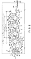
- Fig. 2 is a structural view of the full-color image forming apparatus utilizing the electrophotographic method.
- the apparatus consists of four stations for forming four color images of magenta, cyan, yellow and black.
- Photosensitive drums 1a to 1d are uniformly charged by primary chargers 2a to 2d and a light emitted by a semiconductor laser (not shown) driven by each color image signal is exposure scanned on the photosensitive drums 1a to 1d by a polygon mirror 17 to form a latent image.
- the latent image is developed by development devices 3a to 3d to form a toner image on the photosensitive drums 1a to 1d.
- the toner image is formed by applying a recording material 6 in a recording material tray 60 on a transfer belt (or a transfer sheet) 8 through a pick-up roller 13a and registration rollers 13b and is then fed. A registration on the recording material 6 is synchronized.
- the image is thereafter multiple-transferred by thermotransfer chargers 4a to 4d, and is discharged outside an image forming apparatus upon fixing it on the recording material through a fixing roller 71 and a pressing roller 72 by means of a separation charger 14 and curvature of a transfer belt holding roller 10.
- the fixing roller 71 consists of a metallic pipe of which surface is coated by a silicone rubber and a fluoro rubber.
- the pressing roller 72 consists of a metallic roller of which surface is coated by the silicone rubber.
- a thermistor 79 and a thermocontrol circuit both mounted on a surface of the pressing roller 72 control halogen heaters 75 and 76, so that a surface temperature of the roller 72 is maintained at a constant value suitable for the fixing process.
- the silicone oil in an oil pool is removed to an oil application roller 77 through an oil pump-up roller 78 for sequentially controlling the oil application roller 77 to contact with or separate from the fixing roller 71.
- an oil control blade 80 is to be held on the fixing roller 71 by an oil control blade 80.
- Cleaning devices 73 and 74 utilize zonal cleaning web members to attain an excellent cleaning with maintaining their fresh surfaces by drawing out and rolling up the web members.
- a means for delaying the fixing feed speed is generally used under a consideration of a waiting time for switching with the reflect recording material and a structural arrangement of the hardware.
- the fixing speed is set suitably for the transparent recording material, it is appeared an area at which a pulse motor cannot uniformly be driven. Further, since heat to be given to a PET sheet becomes unexpectedly large, the transparent recording sheet passes through feed rollers 81 in a thermoplastic state after passing through the fixing roller 71. As a result, there occurs such a defect as the surface of a transparent recording sheet becomes worse.
- European patent specification EP-A-0267566 discloses an image processing apparatus for use in a colour image forming apparatus utilising an ink-jet recording device, said apparatus comprising input means for inputting colour image data having a plurality of colour components, and colour correction means for colour correcting the input colour image data, wherein the apparatus has selectable modes for recording the colour image represented by the colour image data on a transparent recording material and on an non-transparent recording material.
- the colour correction means is provided to correspondingly change and adapt colour correction coefficients so that colour differences between an original and an output image printed on said transparent recording material or on said non-transparent recording material are minimised respectively.
- UK Patent Specification GB-A-2 050751 discloses a color scanner in which look-up tables are utilised which correspond to features of the output device and the recording medium.
- the present invention is applied in consideration of the above-mentioned problems, and is concerned with carrying out color correction of the image data in accordance with the type of the recording material used such that an excellent image can be formed.
- image processing apparatus as set out in claim 1.
- Embodiments of the present invention will be described with reference to a full-color image forming apparatus which can form a full-color image not only on an ordinary opaque sheet but also on a transparent recording medium used for an OHP.
- the full-color image forming apparatus of the present invention reads an original image with performing a color separation to digitalize a read signal. An obtained digital signal is processed in accordance with a necessary image signal forming condition and then output, so that a color image is formed on a recording medium by several color materials on the basis of the output image signal.
- constituted full-color image forming apparatus has almost the same structure as that described in Fig. 2.
- the present embodiments are characterized in generating and processing an image signal for forming a full-color image on a transparent recording medium used for the OHP. The above featured structural portions of the embodiments will be described hereinafter.
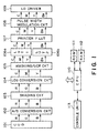
- Fig. 1 is a block diagram showing an entire structure from a charged coupled device (CCD) 101 to an LD driver 109 which drives a semiconductor laser of the present embodiment.
- CCD charged coupled device
- An original is lighted by a light source (not shown) and an obtained reflected light is focused on the CCD 101 by an optical lens system, thereby converting it into an electrical signal.
- image data indicating the original is generated.
- the CCD 101 has a shape in which a three-line array is arranged. Color separating filters of red (R), green (G) and blue (B) are coated on a surface of the CCD element every one line, and a color signal corresponding to each color component of one pixel is generated.
- the analog image data is converted by an analog-to-digital (A/D) converter 102 into 8-bit digital signal. Then, the obtained digital is normalized, on the basis of a luminance signal, by a shading circuit 103, so as to eliminate variation among elements of the CCD 101.
- A/D analog-to-digital
- R, G and B luminance signals are then converted into cyan (C), magenta (M) and yellow (Y) density signals of which colors of C, M and Y are respectively complementary colors of R, G and B.
- a masking process for matching color reproductivity and an under color removal (UCR) process for generating a black (Bk) signal are executed in a masking/UCR circuit 105.
- a gradation conversion process is executed in a look-up table (LUT)1 circuit 106a.
- a gradation conversion process is executed in a LUT 2 circuit 106b.
- a gradation conversion corresponding to a mode (normal mode or transparent recording medium mode) set in a console unit 113 is set by a CPU 110, in the LUT 1 circuit 106a and the LUT 2 circuit 106b.
- a non-linear gamma process set for each color is executed in a printer gamma LUT 107 in accordance with a printer output characteristic.
- a pulse width modulation circuit 108 performs a pulse width modulation by comparing each of the input digital C, M, Y and Bk density signals with a predetermined triangle wave, independently, to convert into analog C, M, Y and Bk density signals. Then, the analog C, M, Y and Bk density signals are output to corresponding color parts of the LD driver 109, respectively.
- the LD driver 109 forms a latent image on a photosensitive drum in the electrophotographic method, on the basis of the input analog C, M, Y and Bk density signals.
- the CPU 110 controls the foregoing each circuit on the basis of a program stored in a ROM 111, by using a RAM 112 as a work-memory.
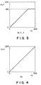
- a conversion characteristic in the transparent recording medium mode is indicated by Figs. 3 and 4.
- Fig. 3 indicates the conversion characteristic of the gradation conversion process of the LUT 1 circuit 106a
- Fig. 4 indicates the same as that of the LUT 2 circuit 106b.
- the Bk signal has the conversion characteristic for outputting the input signal as it is, while the signals of M, C and Y are set to limit the output signal not exceeding the level 180.
- Figs. 5 and 6 are cross-sectional views in a case where an image is formed on a transparent recording material.
- Fig. 5 indicates the state that an image is sufficiently fixed under the condition that a fixing temperature is set at 160°C and a fixing speed is set at 25 mm/sec. In this case, toner grains are sufficiently fused and dispersed in the recorded image holding layer without having the grain shape, and the diffusion of the transmitting light can not be almost observed.
- Fig. 6 indicates the state of being executed the fixing under the condition that a fixing temperature is set at 160°C and a fixing speed is set at 75 mm/sec to avoid the above fatal defect.
- the toner grains are not sufficiently fused because of the insufficient heat, and a toner's grain structure is partially remained. Due to this fact, the incident light is diffused, and the hue of the projected image utilizing the OHP sheet with color toners of M, C and Y becomes hardly diffused as the quantity of toner grows large. As a result, the color of muddy black is appeared.
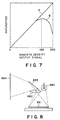
- Fig. 7 shows the characteristic of the relationship between a density output signal and saturation.
- A indicates the characteristic when the fixing speed is set at 25 mm/sec
- B indicates the characteristic when the fixing speed is set at 75 mm/sec.
- the quantity of toner has to be limited such that the toner grains can be sufficiently fused under the normal fixing temperature and speed in the transparent recording medium.
- the quantity of toner has to be limited such that an upper limitation does not exceed the level 180.
- an image having no extraordinary impression can be formed by avoiding the generation of blur (or muddiness).
- the quantity of toner is limited such that the toner can be fused under the heat capacity to be given by the normal fixing temperature and speed.
- the achromatic component of Bk since reproductivity with the high level becomes important in black characters or the like, it is not required to limit the achromatic component of Bk but is required to limit the chromatic components of Y, M and C.
- the blur (or muddiness) in color can be prevented, the color can be reproduced clearly, and the black character can be reproduced excellently.
- the quantity of toner has not to be limited at the LUT 1, but the gradation conversion process shown in Fig. 4 has to be executed for entire colors of C, M, Y and Bk.
- a gradation conversion table shown in Fig. 4 has to be set.
- the most suitable process in accordance with the kind of the recording medium can be executed.
- the most suitable state can be realized for the case where an image is projected by, especially, the reflection-type OHP.
- the color may be observed thin in an OHP image formed under the condition of the first embodiment.
- Fig. 8 is a structural view of the reflection-type OHP and Fig. 9 is a structural view of the transmission-type OHP.
- a light source 880 irradiates an OHP original 881, and the reflected light is projected on a screen 884 via a lens system 882 and a mirror 883.
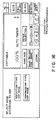
- the most suitable condition fitting to the different type of OHP is registered in a ROM 210 for being selected by an user with a display screen of a console unit 212 shown in Fig. 16, and a CPU 211 loads the LUT value to be switched the parameter.
- the gradation conversion characteristics of M, C and Y are set to the same as that of black Bk shown in Fig. 4.
- the most suitable OHP sheet can be provided in accordance with the kind of OHP which is often used by an user.
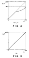
- the combination of the gradation conversion characteristic to be set in a LUT 1 and a LUT 2 may be such combinations as shown in Figs. 12 to 15.
- a non-linear gradation conversion characteristic is set for the LUT 1 so that an excellent gradation may be maintained until the input level 255.
- a printer gamma LUT 107 may be properly set to be corresponded to the varying of the output characteristic of a printer according to a calibration or the like.
- the LUT 1 and the LUT 2 may be set so that the CPU controls and corrects the foregoing gradation conversion characteristic which is set with the mode corresponding to the foregoing recording medium for setting a table on the basis of the color-balance set by a console unit or the kind of images (characters, photograph or map).
- the most suitable OHP image was obtained utilizing the gradation conversion of a gamma LUT, however, in the present embodiment, it is characterized that a desired characteristic can be obtained by a color space conversion.
- Fig. 11 is a block diagram of the third embodiment.
- a color space conversion circuit 112 is provided between a shading circuit 103 and a LOG conversion circuit 104.
- the present embodiment is supported by the following matrix calculation, and for an entire color space, the luminocity, the hue and the saturation can be controlled depending on the parameter of a matrix.
- the same effect as that of the first embodiment can be obtained under the setting of without using the high-density to increase the luminocity.
- the image signal with the different image signal forming condition depending on the image signal process means is to be output against a black image signal portion and a color image signal portion, respectively, and the image forming means forms a color image on the transparent recording medium utilizing plural color materials on the basis of the image signal.
- This formed image can be projected as a full-color image having excellent colors by an image projector (OHP).
- a control means stores a mode setting the most suitable image signal forming condition against the kind of an image projector and such a mode can be selected by an user, an image to be projected with an excellent color-tone/density full-color image corresponding to the kind of OHP can be easily formed for an user who utilizes several kinds of OHPs.
Description
- The present invention relates to a color image processing apparatus and method for color processing images.
- Hitherto, a method for projecting images on a screen or the like by utilizing an image projector such as an overhead projector (hereinafter referred to as OHP) by forming images on a transparent sheet by a full-color image forming apparatus which depends on such methods as an electrophotography, an ink-jetting, a thermotransfer recording and the like has been widely used and an importance thereof will become more serious in future.
- As an OHP image sheet, a resin sheet such as an polyethylene (PET) or the like having a thickness of 100 to 150 µm is widely used and a desired recorded image holding layer is provided on the resin sheet if it is required in order to improve a fixing, a holding or a resolution of images.
- An image forming method which depends on the full-color image forming apparatus utilizing an electrophotographic method will be described hereinafter.
- Fig. 2 is a structural view of the full-color image forming apparatus utilizing the electrophotographic method.
- In the drawing, the apparatus consists of four stations for forming four color images of magenta, cyan, yellow and black. Photosensitive drums 1a to 1d are uniformly charged by primary chargers 2a to 2d and a light emitted by a semiconductor laser (not shown) driven by each color image signal is exposure scanned on the photosensitive drums 1a to 1d by a
polygon mirror 17 to form a latent image. The latent image is developed by development devices 3a to 3d to form a toner image on the photosensitive drums 1a to 1d. - The toner image is formed by applying a
recording material 6 in a recording material tray 60 on a transfer belt (or a transfer sheet) 8 through a pick-up roller 13a andregistration rollers 13b and is then fed. A registration on therecording material 6 is synchronized. The image is thereafter multiple-transferred bythermotransfer chargers 4a to 4d, and is discharged outside an image forming apparatus upon fixing it on the recording material through afixing roller 71 and apressing roller 72 by means of aseparation charger 14 and curvature of a transfer belt holding roller 10. - Next, there will be explained as to a fixing process.
- The
fixing roller 71 consists of a metallic pipe of which surface is coated by a silicone rubber and a fluoro rubber. Thepressing roller 72 consists of a metallic roller of which surface is coated by the silicone rubber. A thermistor 79 and a thermocontrol circuit (not shown) both mounted on a surface of thepressing roller 72control halogen heaters roller 72 is maintained at a constant value suitable for the fixing process. - The silicone oil in an oil pool is removed to an
oil application roller 77 through an oil pump-up roller 78 for sequentially controlling theoil application roller 77 to contact with or separate from thefixing roller 71. Thus, a constant quantity of oil is to be held on thefixing roller 71 by an oil control blade 80. -
Cleaning devices - In case of forming a full-color image on a transparent recording material, it is preferable to increase a fixing set temperature, to decrease a fixing feed speed or to increase a fixing pressure, as compared with a case of fixing a reflect recording material. This is because the sufficient heat is added so as not to remain the grain form of each color toner in the recorded image holding layer on a PET sheet. In order to realize such an operation, a means for delaying the fixing feed speed is generally used under a consideration of a waiting time for switching with the reflect recording material and a structural arrangement of the hardware.
- However, if the fixing speed is set suitably for the transparent recording material, it is appeared an area at which a pulse motor cannot uniformly be driven. Further, since heat to be given to a PET sheet becomes unexpectedly large, the transparent recording sheet passes through
feed rollers 81 in a thermoplastic state after passing through thefixing roller 71. As a result, there occurs such a defect as the surface of a transparent recording sheet becomes worse. - It should be noted that, since probability that the fused toner adheres to the fixing roller becomes large in an area where a great deal of toner is transferred at a high concentration (or density) area of an image, there occurs such an image defect as the density of the high concentration area becomes thin. Moreover, the transparent recording sheet becomes likely to entwine around the fixing roller because of the tackiness of the fused toner. If the sheet entwines around the fixing roller, a serious damage will be occurred in an image forming apparatus.
- European patent specification EP-A-0267566 discloses an image processing apparatus for use in a colour image forming apparatus utilising an ink-jet recording device, said apparatus comprising input means for inputting colour image data having a plurality of colour components, and colour correction means for colour correcting the input colour image data, wherein the apparatus has selectable modes for recording the colour image represented by the colour image data on a transparent recording material and on an non-transparent recording material. In this prior art apparatus, the colour correction means is provided to correspondingly change and adapt colour correction coefficients so that colour differences between an original and an output image printed on said transparent recording material or on said non-transparent recording material are minimised respectively.
- UK Patent Specification GB-A-2 050751 discloses a color scanner in which look-up tables are utilised which correspond to features of the output device and the recording medium.
- The present invention is applied in consideration of the above-mentioned problems, and is concerned with carrying out color correction of the image data in accordance with the type of the recording material used such that an excellent image can be formed.
- In accordance with one aspect of the present invention there is provided image processing apparatus as set out in
claim 1. - In accordance with a second aspect of the present invention there is provided an image processing method as set out in
claim 7. -
- Fig. 1 is a block diagram showing a structural example of an image forming apparatus according to the first embodiment;
- Fig. 2 shows a structural example of a full-color image forming apparatus;
- Fig. 3 shows a gradation conversion characteristic of M, C and Y;
- Fig. 4 shows a gradation conversion characteristic of Bk;
- Fig. 5 is a cross-sectional view of an OHP sheet in case where it is sufficiently fixed;
- Fig. 6 is a cross-sectional view of an OHP sheet in case where it is fixed with the safety fixing speed;
- Fig. 7 shows a characteristic of the relationship between a density output signal of magenta and the saturation;
- Fig. 8 is a structural view of a reflection-type OHP;
- Fig. 9 is a structural view of a transmission-type OHP;
- Fig. 10 is a block diagram showing a structural example of an image forming apparatus according to the second embodiment;
- Fig. 11 is a block diagram showing a structural example of an image forming apparatus according to the third embodiment;
- Fig. 12 shows a modified example of the gradation conversion characteristic of M, C and Y;
- Fig. 13 shows a modified example of the gradation conversion characteristic of Bk;
- Fig. 14 shows a second modified example of the gradation conversion characteristic of M, C and Y;
- Fig. 15 shows a second modified example of the gradation conversion characteristic of Bk; and
- Fig. 16 shows an example of a console unit.
-
- Embodiments of the present invention will be described with reference to a full-color image forming apparatus which can form a full-color image not only on an ordinary opaque sheet but also on a transparent recording medium used for an OHP.
- The full-color image forming apparatus of the present invention reads an original image with performing a color separation to digitalize a read signal. An obtained digital signal is processed in accordance with a necessary image signal forming condition and then output, so that a color image is formed on a recording medium by several color materials on the basis of the output image signal. Thus, constituted full-color image forming apparatus has almost the same structure as that described in Fig. 2. The present embodiments are characterized in generating and processing an image signal for forming a full-color image on a transparent recording medium used for the OHP. The above featured structural portions of the embodiments will be described hereinafter.
- An embodiment of the present invention will be described in detail hereinafter with reference to the accompanying drawings.
- Fig. 1 is a block diagram showing an entire structure from a charged coupled device (CCD) 101 to an
LD driver 109 which drives a semiconductor laser of the present embodiment. - An original is lighted by a light source (not shown) and an obtained reflected light is focused on the
CCD 101 by an optical lens system, thereby converting it into an electrical signal. Thus, image data indicating the original is generated. - The
CCD 101 has a shape in which a three-line array is arranged. Color separating filters of red (R), green (G) and blue (B) are coated on a surface of the CCD element every one line, and a color signal corresponding to each color component of one pixel is generated. - The analog image data is converted by an analog-to-digital (A/D)
converter 102 into 8-bit digital signal. Then, the obtained digital is normalized, on the basis of a luminance signal, by ashading circuit 103, so as to eliminate variation among elements of theCCD 101. - By a
log conversion circuit 104, R, G and B luminance signals are then converted into cyan (C), magenta (M) and yellow (Y) density signals of which colors of C, M and Y are respectively complementary colors of R, G and B. - Next, a masking process for matching color reproductivity and an under color removal (UCR) process for generating a black (Bk) signal are executed in a masking/
UCR circuit 105. - For the C, M and Y density signals indicating chromatic color components, a gradation conversion process is executed in a look-up table (LUT)1
circuit 106a. On the other hand, for the black (Bk) signal indicating achromatic color component, a gradation conversion process is executed in a LUT 2 circuit 106b. - It should be noted that a gradation conversion corresponding to a mode (normal mode or transparent recording medium mode) set in a
console unit 113 is set by aCPU 110, in theLUT 1circuit 106a and the LUT 2 circuit 106b. - For the C, M and Y density signals which have been gradation-conversion processed in the
LUT 1 and the LUT 2, a non-linear gamma process set for each color is executed in aprinter gamma LUT 107 in accordance with a printer output characteristic. - A pulse
width modulation circuit 108 performs a pulse width modulation by comparing each of the input digital C, M, Y and Bk density signals with a predetermined triangle wave, independently, to convert into analog C, M, Y and Bk density signals. Then, the analog C, M, Y and Bk density signals are output to corresponding color parts of theLD driver 109, respectively. - The
LD driver 109 forms a latent image on a photosensitive drum in the electrophotographic method, on the basis of the input analog C, M, Y and Bk density signals. - It should be noted that the
CPU 110 controls the foregoing each circuit on the basis of a program stored in aROM 111, by using aRAM 112 as a work-memory. - Next, the gradation conversion process of the
LUT 1 and the LUT 2 in the transparent recording medium mode and the normal mode will be described. - A conversion characteristic in the transparent recording medium mode is indicated by Figs. 3 and 4.
- Fig. 3 indicates the conversion characteristic of the gradation conversion process of the
LUT 1circuit 106a, and Fig. 4 indicates the same as that of the LUT 2 circuit 106b. - As shown in the drawings, the Bk signal has the conversion characteristic for outputting the input signal as it is, while the signals of M, C and Y are set to limit the output signal not exceeding the
level 180. - The reason for setting like this will be described hereinafter.
- Figs. 5 and 6 are cross-sectional views in a case where an image is formed on a transparent recording material.
- Fig. 5 indicates the state that an image is sufficiently fixed under the condition that a fixing temperature is set at 160°C and a fixing speed is set at 25 mm/sec. In this case, toner grains are sufficiently fused and dispersed in the recorded image holding layer without having the grain shape, and the diffusion of the transmitting light can not be almost observed.
- In such a state, a hue of the image projected to a screen by utilizing an OHP sheet on which the image is formed by color toners of M, C and Y is clear, and the image having excellent color productivity can be obtained.
- However, if the fixing speed is set more slowly than that of ordinary case in order to set the fixing speed suitable for the transparent recording medium, it is appeared an area at which a pulse motor cannot uniformly be driven. Further, since heat to be given to a PET sheet becomes unexpectedly large, the transparent recording sheet passes through
feed rollers 81 in a thermoplastic state after passing through the fixing roller. As a result, there occurs such a defect as the surface of a transparent recording sheet becomes worse. Further, probability that the fused toner adheres to the fixing roller becomes large in an area where a great deal of toner is transferred at a high concentration (or density) area of an image. Therefore, there occurs such an image defect as the density of the high concentration (or density) area becomes low. Moreover, due to tackiness of the fused toner, a serious damage will be occurred in the image forming apparatus, this fact may become the fatal defect for the image forming apparatus. - Fig. 6 indicates the state of being executed the fixing under the condition that a fixing temperature is set at 160°C and a fixing speed is set at 75 mm/sec to avoid the above fatal defect.
- In this case, the toner grains are not sufficiently fused because of the insufficient heat, and a toner's grain structure is partially remained. Due to this fact, the incident light is diffused, and the hue of the projected image utilizing the OHP sheet with color toners of M, C and Y becomes hardly diffused as the quantity of toner grows large. As a result, the color of muddy black is appeared.
- Fig. 7 shows the characteristic of the relationship between a density output signal and saturation. In Fig. 7, A indicates the characteristic when the fixing speed is set at 25 mm/sec, and B indicates the characteristic when the fixing speed is set at 75 mm/sec.
- According to a curve indicated by B, it is understood that blur (or muddiness) is appeared from about 180 level in the density output signal value.
- That is, as described above, it is understood that the toner grains are not sufficiently fused because of the insufficient heat.
- As above, in case of utilizing the transparent recording medium, a large heat is required in order to fuse the toner grains as compared with the case of utilizing an ordinary sheet.
- However, if the fixing speed is delayed in order to give the sufficient heat capacity, there occurs the above-mentioned problems.
- While, even if the fixing temperature is increased, such another problem as the state of thermoplasticity or the like will be occurred.
- Therefore, in the present embodiment, as apparent from Fig. 7, the quantity of toner has to be limited such that the toner grains can be sufficiently fused under the normal fixing temperature and speed in the transparent recording medium.
- That is, as to the chromatic components of M, C and Y, even if a density input signal exceeding the
level 180 exists, as shown in Fig. 3, the quantity of toner has to be limited such that an upper limitation does not exceed thelevel 180. - In the present invention, in consideration of a total image quality, an image having no extraordinary impression can be formed by avoiding the generation of blur (or muddiness).
- While, as to the achromatic component of Bk, character information becomes important at a level exceeding the
level 180 in the character reproduction quality, and the probability that the level of Bk does not exceed thelevel 180 is extremely large in a gradation image area due to the UCR processing when an image is in the normal state. In this point of view, it is not required to set any limitation for the component Bk. - As described above, in the transparent recording medium mode, the quantity of toner is limited such that the toner can be fused under the heat capacity to be given by the normal fixing temperature and speed.
- Further, as to the achromatic component of Bk, since reproductivity with the high level becomes important in black characters or the like, it is not required to limit the achromatic component of Bk but is required to limit the chromatic components of Y, M and C.
- Accordingly, the blur (or muddiness) in color can be prevented, the color can be reproduced clearly, and the black character can be reproduced excellently.
- In a case where a normal mode is designated, an image can be excellently reproduced until the high density portion, at the normal fixing speed and temperature.
- Therefore, the quantity of toner has not to be limited at the
LUT 1, but the gradation conversion process shown in Fig. 4 has to be executed for entire colors of C, M, Y and Bk. - That is, for the
LUT 1 and the LUT 2, a gradation conversion table shown in Fig. 4 has to be set. - As described above, according to the present embodiment, the most suitable process in accordance with the kind of the recording medium can be executed.
- By providing the above setting, as to an image projected by the OHP, especially by a reflective type OHP, an excellent quality can be obtained.
- In the first embodiment, the most suitable state can be realized for the case where an image is projected by, especially, the reflection-type OHP.
- However, in a case where an image is projected by a transmission-type OHP, the color may be observed thin in an OHP image formed under the condition of the first embodiment.
- Fig. 8 is a structural view of the reflection-type OHP and Fig. 9 is a structural view of the transmission-type OHP.
- In the reflection-type OHP shown in Fig. 8, a
light source 880 irradiates an OHP original 881, and the reflected light is projected on ascreen 884 via alens system 882 and amirror 883. - In this case, since the light passes through the OHP original two times, the light is also shielded and diffused respectively two times. This fact causes a great loss of the light until reaching to a screen.
- On the other hand, in a case where a transmission-type OHP is used, since the light passes through an OHP original 981 only one time, resulting in a little loss of the light.
- Therefore, in a case where a transmission-type OHP is used, since the loss of light is relatively small, it is almost needless to notice a color blur (or muddiness). Accordingly, the process having an importance on reproducing the color deeply is executed.
- Therefore, in the present embodiment, as shown in Fig. 10, the most suitable condition fitting to the different type of OHP is registered in a
ROM 210 for being selected by an user with a display screen of aconsole unit 212 shown in Fig. 16, and a CPU 211 loads the LUT value to be switched the parameter. - As a definite parameter of the transmission-type OHP, the gradation conversion characteristics of M, C and Y are set to the same as that of black Bk shown in Fig. 4.
- Accordingly, the most suitable OHP sheet can be provided in accordance with the kind of OHP which is often used by an user.
- Here, the description is given by utilizing only two modes, however, it is needless to say that the most suitable condition corresponding to the used OHP can be selected by varying the limiting value on a console unit.
- Further, it is effective to modify the gradation conversion characteristic to a non-linear curved shape.
- Further, the combination of the gradation conversion characteristic to be set in a
LUT 1 and a LUT 2 may be such combinations as shown in Figs. 12 to 15. - That is, a non-linear gradation conversion characteristic is set for the
LUT 1 so that an excellent gradation may be maintained until theinput level 255. - A
printer gamma LUT 107 may be properly set to be corresponded to the varying of the output characteristic of a printer according to a calibration or the like. - The
LUT 1 and the LUT 2 may be set so that the CPU controls and corrects the foregoing gradation conversion characteristic which is set with the mode corresponding to the foregoing recording medium for setting a table on the basis of the color-balance set by a console unit or the kind of images (characters, photograph or map). - In the above described embodiment, the most suitable OHP image was obtained utilizing the gradation conversion of a gamma LUT, however, in the present embodiment, it is characterized that a desired characteristic can be obtained by a color space conversion.
- Fig. 11 is a block diagram of the third embodiment.
- As shown in Fig. 11, a color
space conversion circuit 112 is provided between ashading circuit 103 and aLOG conversion circuit 104. - Here, the present embodiment is supported by the following matrix calculation, and for an entire color space, the luminocity, the hue and the saturation can be controlled depending on the parameter of a matrix.

- If the OHP mode is selected, the same effect as that of the first embodiment can be obtained under the setting of without using the high-density to increase the luminocity.
- As described above, according to the present invention, when an image is formed on a transparent recording medium, the image signal with the different image signal forming condition depending on the image signal process means is to be output against a black image signal portion and a color image signal portion, respectively, and the image forming means forms a color image on the transparent recording medium utilizing plural color materials on the basis of the image signal. This formed image can be projected as a full-color image having excellent colors by an image projector (OHP).
- Further, depending on the constitution that a control means stores a mode setting the most suitable image signal forming condition against the kind of an image projector and such a mode can be selected by an user, an image to be projected with an excellent color-tone/density full-color image corresponding to the kind of OHP can be easily formed for an user who utilizes several kinds of OHPs.
Claims (7)
- An image processing apparatus for use in a colour image forming apparatus utilizing an electrophotographic recording method by which a toner image is formed on a recording material (6) by fusing toner grains, said apparatus comprising:characterised in that the apparatus has selectable modes for recording the colour image represented by the colour image data on a transparent recording material and on a non-transparent recording material, and wherein when the apparatus is in the mode for recording a colour image on a transparent recording material said colour correction means is adapted to perform a colour correction which limits the output levels of the chromatic components such that the maximum output quantity of the toner used for recording is less than that one used for recording in the ordinary recording mode so as to facilitate fusing the toner grains in said transparent recording mode.input means (101) for inputting colour image data having a plurality of colour components comprising chromatic and achromatic components, andcolour correction means (106a,106b) for colour correcting said input colour image data,
- Apparatus according to claim 1, wherein said colour correction means (106a,106b) is adapted to execute a gradation correction of the input colour data.
- Apparatus according to claim 1 and 2, wherein, in the transparent recording mode, the gradation correction performed by said colour correction means (106a,106b) is clipped at a predetermined output level for said chromatic components.
- Apparatus according to claim 2 or claim 3, wherein the gradation correction for said chromatic components is non-linear.
- Apparatus according to any preceding claim, further comprising:generation means (101) for generating said colour image data by scanning an original image; andimage formation means (109) for forming an image on a recording material on the basis of the colour corrected colour image data.
- Apparatus according to any preceding claim, wherein said colour correction means (106a,106b) is adapted to perform a colour space conversion.
- An image processing method utilizing electrophotographic recording in which a toner image is formed on recording material (6) by fusing toner grains, comprising the steps of:inputting colour image data having a plurality of colour components comprising chromatic components and an achromatic component; andcorrecting the input colour image data, characterised by carrying out either a transparent recording step in which a colour image represented by the colour image data is recorded on a transparent recording material or an ordinary recording step in which a colour image represented by the colour image data is recorded on non-transparent recording material,wherein said correcting step performs a colour correction which limits the output levels of the chromatic components in the transparent recording step such that the maximum output quality of the toner used for recording is less than that one used for recording in the ordinary recording step so as to facilitate fusing of the toner grains in the transparent recording step.
Applications Claiming Priority (3)
| Application Number | Priority Date | Filing Date | Title |
|---|---|---|---|
| JP17812794 | 1994-07-29 | ||
| JP178127/94 | 1994-07-29 | ||
| JP17812794 | 1994-07-29 |
Publications (3)
| Publication Number | Publication Date |
|---|---|
| EP0695080A2 EP0695080A2 (en) | 1996-01-31 |
| EP0695080A3 EP0695080A3 (en) | 1996-05-29 |
| EP0695080B1 true EP0695080B1 (en) | 2001-10-10 |
Family
ID=16043134
Family Applications (1)
| Application Number | Title | Priority Date | Filing Date |
|---|---|---|---|
| EP95305302A Expired - Lifetime EP0695080B1 (en) | 1994-07-29 | 1995-07-28 | Image processing apparatus and method thereof |
Country Status (3)
| Country | Link |
|---|---|
| US (1) | US5937087A (en) |
| EP (1) | EP0695080B1 (en) |
| DE (1) | DE69523101T2 (en) |
Families Citing this family (13)
| Publication number | Priority date | Publication date | Assignee | Title |
|---|---|---|---|---|
| JP2747987B2 (en) * | 1995-05-23 | 1998-05-06 | セイコー電子機器株式会社 | Color correction device |
| JP3254183B2 (en) * | 1997-05-08 | 2002-02-04 | 株式会社セイコーアイ・インフォテック | Method and apparatus for creating color conversion table |
| US5966507A (en) * | 1997-08-25 | 1999-10-12 | Hewlett-Packard Company | Image resolution enhancement technology (IRET) for dual dye-load inkjet printer |
| JP3984696B2 (en) | 1998-01-30 | 2007-10-03 | キヤノン株式会社 | Image forming apparatus and image forming method |
| US6169609B1 (en) * | 1998-06-09 | 2001-01-02 | Hewlett-Packard Company | Imaging device and method for implementing a color map with K-only black point while reducing interpolator artifacts |
| US20020012126A1 (en) * | 1999-12-20 | 2002-01-31 | Hiroaki Nakamura | Image processing method and apparatus |
| US20030236512A1 (en) * | 2002-06-19 | 2003-12-25 | Baker Andrew A. | Absorbent core with folding zones for absorbency distribution |
| US7283048B2 (en) * | 2003-02-03 | 2007-10-16 | Ingrid, Inc. | Multi-level meshed security network |
| US7042353B2 (en) * | 2003-02-03 | 2006-05-09 | Ingrid, Inc. | Cordless telephone system |
| JP2005059585A (en) * | 2003-07-30 | 2005-03-10 | Canon Inc | Image processing device, image processing method and computer program |
| US8045238B2 (en) * | 2007-09-14 | 2011-10-25 | Kabushiki Kaisha Toshiba | Image processing apparatus, image processing method and image reading apparatus |
| US9204016B2 (en) * | 2011-08-11 | 2015-12-01 | Consolidated Graphics, Inc. | In-process color management system and method for digital color printing |
| US9224074B2 (en) * | 2011-08-11 | 2015-12-29 | Consolidated Graphics, Inc. | System and method for tuning device link profiles for color printing |
Family Cites Families (18)
| Publication number | Priority date | Publication date | Assignee | Title |
|---|---|---|---|---|
| GB2050751B (en) * | 1979-05-30 | 1983-06-29 | Crosfield Electronics Ltd | Image-reproduction apparatus |
| US4481542A (en) * | 1982-03-18 | 1984-11-06 | Advanced Imaging Devices, Inc. | Color video hardcopy recorder, method and media therefor |
| ATE11968T1 (en) * | 1982-04-10 | 1985-03-15 | Hell Rudolf Dr Ing Gmbh | FOUR-COLOR PRINTING PROCESS WITH TONE DEPENDENT COLOR REMOVAL. |
| US4642681A (en) * | 1982-10-08 | 1987-02-10 | Canon Kabushiki Kaisha | Color image processing apparatus for generating color output signals and a black output signal in a mutually exclusive manner |
| JPH0683371B2 (en) * | 1982-10-20 | 1994-10-19 | キヤノン株式会社 | Information reader |
| EP0225100B1 (en) * | 1985-11-18 | 1994-06-22 | Canon Kabushiki Kaisha | Electronic image-forming apparatus |
| JPH0738685B2 (en) * | 1986-11-10 | 1995-04-26 | キヤノン株式会社 | Color image recording device |
| EP0606128B1 (en) * | 1986-11-14 | 1999-02-17 | Canon Kabushiki Kaisha | Color image processing apparatus |
| DE3856285T2 (en) * | 1987-08-11 | 1999-06-10 | Canon Kk | Device for producing color images |
| JP2728886B2 (en) * | 1988-07-20 | 1998-03-18 | キヤノン株式会社 | Image processing device |
| JP2756280B2 (en) * | 1988-11-14 | 1998-05-25 | キヤノン株式会社 | Color image processing equipment |
| US5267031A (en) * | 1988-11-14 | 1993-11-30 | Canon Kabushiki Kaisha | Color image processing apparatus |
| JP3267289B2 (en) * | 1989-05-10 | 2002-03-18 | キヤノン株式会社 | Color image processing method |
| US5408342A (en) * | 1993-02-25 | 1995-04-18 | Canon Kabushiki Kaisha | Color image processing apparatus, method, and printer driver |
| JPH05276368A (en) * | 1992-03-26 | 1993-10-22 | Canon Inc | Color picture processing method and its device |
| JP3472312B2 (en) * | 1992-04-10 | 2003-12-02 | 富士ゼロックス株式会社 | Color image processing method and apparatus |
| JP3233982B2 (en) * | 1992-05-29 | 2001-12-04 | キヤノン株式会社 | Image forming apparatus and image processing method |
| JPH05347714A (en) * | 1992-06-12 | 1993-12-27 | Canon Inc | Color image generating device |
-
1995
- 1995-07-27 US US08/508,259 patent/US5937087A/en not_active Expired - Lifetime
- 1995-07-28 DE DE69523101T patent/DE69523101T2/en not_active Expired - Fee Related
- 1995-07-28 EP EP95305302A patent/EP0695080B1/en not_active Expired - Lifetime
Also Published As
| Publication number | Publication date |
|---|---|
| EP0695080A2 (en) | 1996-01-31 |
| DE69523101T2 (en) | 2002-05-02 |
| DE69523101D1 (en) | 2001-11-15 |
| EP0695080A3 (en) | 1996-05-29 |
| US5937087A (en) | 1999-08-10 |
Similar Documents
| Publication | Publication Date | Title |
|---|---|---|
| US5345320A (en) | Color image data processing apparatus comprising monochrome pixel detector | |
| US5239370A (en) | Color image forming apparatus having color-correcting unit operating in accordance with a gamut of an image input medium | |
| US5282046A (en) | Color image forming apparatus having a color-correcting unit | |
| EP0695080B1 (en) | Image processing apparatus and method thereof | |
| US5162860A (en) | Color image forming apparatus controlling glossiness of an image | |
| US5268753A (en) | Color image forming apparatus and method thereof with color-correcting operation | |
| US6097501A (en) | Color correction device | |
| JP3335507B2 (en) | Color image adjustment apparatus and color image adjustment method | |
| JPH09172547A (en) | Color image forming device | |
| US5633953A (en) | Image processing apparatus having improved color-reproducibility of color image | |
| JPH07322080A (en) | Color picture reader | |
| JP3673561B2 (en) | Image processing method and apparatus | |
| JPH09130623A (en) | Color copying machine | |
| JP2003341186A (en) | Imaging apparatus | |
| US5245419A (en) | Color image forming apparatus and method and apparatus for processing color image | |
| JP3150272B2 (en) | Image processing apparatus and method | |
| JPS6351631B2 (en) | ||
| JPH0851536A (en) | Image processing method and device therefor | |
| US6546131B1 (en) | Image processing method and apparatus for achieving tone reproduction suited to the image | |
| US5495340A (en) | Image reading apparatus having color correction according to tempeature change improved | |
| JP2755972B2 (en) | Color image processing equipment | |
| JPH11266366A (en) | Image copying machine | |
| JPH0879549A (en) | Picture processor | |
| JP3306875B2 (en) | Image forming device | |
| JPH10210314A (en) | Digital image-processing unit |
Legal Events
| Date | Code | Title | Description |
|---|---|---|---|
| PUAI | Public reference made under article 153(3) epc to a published international application that has entered the european phase |
Free format text: ORIGINAL CODE: 0009012 |
|
| AK | Designated contracting states |
Kind code of ref document: A2 Designated state(s): DE FR GB IT |
|
| PUAL | Search report despatched |
Free format text: ORIGINAL CODE: 0009013 |
|
| AK | Designated contracting states |
Kind code of ref document: A3 Designated state(s): DE FR GB IT |
|
| 17P | Request for examination filed |
Effective date: 19961009 |
|
| 17Q | First examination report despatched |
Effective date: 19981006 |
|
| GRAG | Despatch of communication of intention to grant |
Free format text: ORIGINAL CODE: EPIDOS AGRA |
|
| GRAG | Despatch of communication of intention to grant |
Free format text: ORIGINAL CODE: EPIDOS AGRA |
|
| GRAH | Despatch of communication of intention to grant a patent |
Free format text: ORIGINAL CODE: EPIDOS IGRA |
|
| GRAH | Despatch of communication of intention to grant a patent |
Free format text: ORIGINAL CODE: EPIDOS IGRA |
|
| GRAA | (expected) grant |
Free format text: ORIGINAL CODE: 0009210 |
|
| AK | Designated contracting states |
Kind code of ref document: B1 Designated state(s): DE FR GB IT |
|
| REF | Corresponds to: |
Ref document number: 69523101 Country of ref document: DE Date of ref document: 20011115 |
|
| ET | Fr: translation filed | ||
| REG | Reference to a national code |
Ref country code: GB Ref legal event code: IF02 |
|
| PLBE | No opposition filed within time limit |
Free format text: ORIGINAL CODE: 0009261 |
|
| STAA | Information on the status of an ep patent application or granted ep patent |
Free format text: STATUS: NO OPPOSITION FILED WITHIN TIME LIMIT |
|
| 26N | No opposition filed | ||
| PGFP | Annual fee paid to national office [announced via postgrant information from national office to epo] |
Ref country code: DE Payment date: 20070731 Year of fee payment: 13 |
|
| PGFP | Annual fee paid to national office [announced via postgrant information from national office to epo] |
Ref country code: GB Payment date: 20070713 Year of fee payment: 13 |
|
| PGFP | Annual fee paid to national office [announced via postgrant information from national office to epo] |
Ref country code: IT Payment date: 20070710 Year of fee payment: 13 |
|
| PGFP | Annual fee paid to national office [announced via postgrant information from national office to epo] |
Ref country code: FR Payment date: 20070720 Year of fee payment: 13 |
|
| GBPC | Gb: european patent ceased through non-payment of renewal fee |
Effective date: 20080728 |
|
| PG25 | Lapsed in a contracting state [announced via postgrant information from national office to epo] |
Ref country code: DE Free format text: LAPSE BECAUSE OF NON-PAYMENT OF DUE FEES Effective date: 20090203 |
|
| REG | Reference to a national code |
Ref country code: FR Ref legal event code: ST Effective date: 20090331 |
|
| PG25 | Lapsed in a contracting state [announced via postgrant information from national office to epo] |
Ref country code: GB Free format text: LAPSE BECAUSE OF NON-PAYMENT OF DUE FEES Effective date: 20080728 |
|
| PG25 | Lapsed in a contracting state [announced via postgrant information from national office to epo] |
Ref country code: IT Free format text: LAPSE BECAUSE OF NON-PAYMENT OF DUE FEES Effective date: 20080728 Ref country code: FR Free format text: LAPSE BECAUSE OF NON-PAYMENT OF DUE FEES Effective date: 20080731 |