EP0694396A2 - Recording apparatus for performing complementary recording and recording method therefor - Google Patents
Recording apparatus for performing complementary recording and recording method therefor Download PDFInfo
- Publication number
- EP0694396A2 EP0694396A2 EP95305082A EP95305082A EP0694396A2 EP 0694396 A2 EP0694396 A2 EP 0694396A2 EP 95305082 A EP95305082 A EP 95305082A EP 95305082 A EP95305082 A EP 95305082A EP 0694396 A2 EP0694396 A2 EP 0694396A2
- Authority
- EP
- European Patent Office
- Prior art keywords
- recording
- head
- elements
- ink
- printing
- Prior art date
- Legal status (The legal status is an assumption and is not a legal conclusion. Google has not performed a legal analysis and makes no representation as to the accuracy of the status listed.)
- Granted
Links
Images


Classifications
-
- B—PERFORMING OPERATIONS; TRANSPORTING
- B41—PRINTING; LINING MACHINES; TYPEWRITERS; STAMPS
- B41J—TYPEWRITERS; SELECTIVE PRINTING MECHANISMS, i.e. MECHANISMS PRINTING OTHERWISE THAN FROM A FORME; CORRECTION OF TYPOGRAPHICAL ERRORS
- B41J2/00—Typewriters or selective printing mechanisms characterised by the printing or marking process for which they are designed
- B41J2/005—Typewriters or selective printing mechanisms characterised by the printing or marking process for which they are designed characterised by bringing liquid or particles selectively into contact with a printing material
- B41J2/01—Ink jet
- B41J2/21—Ink jet for multi-colour printing
- B41J2/2132—Print quality control characterised by dot disposition, e.g. for reducing white stripes or banding
- B41J2/2139—Compensation for malfunctioning nozzles creating dot place or dot size errors
-
- B—PERFORMING OPERATIONS; TRANSPORTING
- B41—PRINTING; LINING MACHINES; TYPEWRITERS; STAMPS
- B41J—TYPEWRITERS; SELECTIVE PRINTING MECHANISMS, i.e. MECHANISMS PRINTING OTHERWISE THAN FROM A FORME; CORRECTION OF TYPOGRAPHICAL ERRORS
- B41J2/00—Typewriters or selective printing mechanisms characterised by the printing or marking process for which they are designed
- B41J2/005—Typewriters or selective printing mechanisms characterised by the printing or marking process for which they are designed characterised by bringing liquid or particles selectively into contact with a printing material
- B41J2/01—Ink jet
- B41J2/07—Ink jet characterised by jet control
-
- B—PERFORMING OPERATIONS; TRANSPORTING
- B41—PRINTING; LINING MACHINES; TYPEWRITERS; STAMPS
- B41J—TYPEWRITERS; SELECTIVE PRINTING MECHANISMS, i.e. MECHANISMS PRINTING OTHERWISE THAN FROM A FORME; CORRECTION OF TYPOGRAPHICAL ERRORS
- B41J2/00—Typewriters or selective printing mechanisms characterised by the printing or marking process for which they are designed
- B41J2/005—Typewriters or selective printing mechanisms characterised by the printing or marking process for which they are designed characterised by bringing liquid or particles selectively into contact with a printing material
- B41J2/01—Ink jet
- B41J2/21—Ink jet for multi-colour printing
- B41J2/2132—Print quality control characterised by dot disposition, e.g. for reducing white stripes or banding
-
- B—PERFORMING OPERATIONS; TRANSPORTING
- B41—PRINTING; LINING MACHINES; TYPEWRITERS; STAMPS
- B41J—TYPEWRITERS; SELECTIVE PRINTING MECHANISMS, i.e. MECHANISMS PRINTING OTHERWISE THAN FROM A FORME; CORRECTION OF TYPOGRAPHICAL ERRORS
- B41J3/00—Typewriters or selective printing or marking mechanisms characterised by the purpose for which they are constructed
- B41J3/407—Typewriters or selective printing or marking mechanisms characterised by the purpose for which they are constructed for marking on special material
- B41J3/4078—Printing on textile
-
- G—PHYSICS
- G06—COMPUTING; CALCULATING OR COUNTING
- G06K—GRAPHICAL DATA READING; PRESENTATION OF DATA; RECORD CARRIERS; HANDLING RECORD CARRIERS
- G06K15/00—Arrangements for producing a permanent visual presentation of the output data, e.g. computer output printers
- G06K15/02—Arrangements for producing a permanent visual presentation of the output data, e.g. computer output printers using printers
- G06K15/10—Arrangements for producing a permanent visual presentation of the output data, e.g. computer output printers using printers by matrix printers
-
- B—PERFORMING OPERATIONS; TRANSPORTING
- B41—PRINTING; LINING MACHINES; TYPEWRITERS; STAMPS
- B41J—TYPEWRITERS; SELECTIVE PRINTING MECHANISMS, i.e. MECHANISMS PRINTING OTHERWISE THAN FROM A FORME; CORRECTION OF TYPOGRAPHICAL ERRORS
- B41J19/00—Character- or line-spacing mechanisms
- B41J19/14—Character- or line-spacing mechanisms with means for effecting line or character spacing in either direction
- B41J19/142—Character- or line-spacing mechanisms with means for effecting line or character spacing in either direction with a reciprocating print head printing in both directions across the paper width
-
- B—PERFORMING OPERATIONS; TRANSPORTING
- B41—PRINTING; LINING MACHINES; TYPEWRITERS; STAMPS
- B41J—TYPEWRITERS; SELECTIVE PRINTING MECHANISMS, i.e. MECHANISMS PRINTING OTHERWISE THAN FROM A FORME; CORRECTION OF TYPOGRAPHICAL ERRORS
- B41J2202/00—Embodiments of or processes related to ink-jet or thermal heads
- B41J2202/01—Embodiments of or processes related to ink-jet heads
- B41J2202/12—Embodiments of or processes related to ink-jet heads with ink circulating through the whole print head
-
- G—PHYSICS
- G06—COMPUTING; CALCULATING OR COUNTING
- G06K—GRAPHICAL DATA READING; PRESENTATION OF DATA; RECORD CARRIERS; HANDLING RECORD CARRIERS
- G06K2215/00—Arrangements for producing a permanent visual presentation of the output data
- G06K2215/0082—Architecture adapted for a particular function
- G06K2215/0085—Error recovery
-
- G—PHYSICS
- G06—COMPUTING; CALCULATING OR COUNTING
- G06K—GRAPHICAL DATA READING; PRESENTATION OF DATA; RECORD CARRIERS; HANDLING RECORD CARRIERS
- G06K2215/00—Arrangements for producing a permanent visual presentation of the output data
- G06K2215/111—Arrangements for producing a permanent visual presentation of the output data with overlapping swaths
Landscapes
- Engineering & Computer Science (AREA)
- Quality & Reliability (AREA)
- Physics & Mathematics (AREA)
- Theoretical Computer Science (AREA)
- General Engineering & Computer Science (AREA)
- General Physics & Mathematics (AREA)
- Mathematical Physics (AREA)
- Textile Engineering (AREA)
- Ink Jet (AREA)
- Particle Formation And Scattering Control In Inkjet Printers (AREA)
- Dot-Matrix Printers And Others (AREA)
- Coloring (AREA)
- Accessory Devices And Overall Control Thereof (AREA)
Abstract
Description
- The present invention relates to an ink jet recording apparatus using a liquid discharging head to discharge ink or other liquid. More precisely, the invention relates to a printing apparatus for making given prints on a recording medium such as paper, cloth, nonwoven cloth, or OHP sheet.
- Particularly, the present invention is to provide a printing apparatus capable of executing a continuous printing for a long time or a printing apparatus effectively applicable to making prints continuously on a cloth as wide as more than one meter. More specifically, there are named a printer, copying machine, ink jet printing apparatus, facsimile apparatus, or other office equipment, and a textile printing apparatus or other large industrial equipment as those to which the present invention is applicable.
- As the conventional liquid discharging apparatuses, there are those which discharge ink droplets onto a recording medium to obtain images or those which discharge special liquid for the utilization thereof. An ink jet recording apparatus is to discharge ink droplets onto a recording medium to form images. Unlike the electronic photography or others, it uses a lesser number of devices or equipment that may be required before the formation of images. As a result, there is a significant advantage that the ink jet recording apparatuses are capable of forming intended images more stably.
- In general, however, a discharge unit for discharging liquid is structured extremely fine. Therefore, defective discharges tend to occur due to solidification of dyes or pigments mixed in a liquid or due to adhesion of foreign particles, hence creating a problem that a liquid discharging apparatus such as an ink jet recording apparatus may present defective recording in some cases. In order to avoid the occurrence of a problem of the kind, it is practiced at appropriate intervals that liquid is forcibly exhausted by means of suction, compression, or the like known as recovery means; the discharging area of the discharge unit is cleaned; or gas or fluid is ejected onto the discharging area of the discharge unit.
- Meanwhile, for use of an ink jet recording apparatus, it is desired to execute recording in a higher quality and resolution in consideration of its nature as an excellent recording apparatus. Therefore, its image formation is performed by use of finer nozzles. The use of finer nozzles often results in the creation of the problems described above, which leads to the unstable recording, and degradation of the quality of recorded images. Among the causes in this respect, there are twisted recording brought by the unstable discharging direction of ink with minute displacement of impacting positions of ink droplets; non-discharges due to clogging of discharge ports (nozzles) by adhesion or mixture of dust particles or overly viscous ink; non-discharge due to heater wiring breakdown in the bubble jet method in which air bubbles are created in ink by use of electrothermal transducing elements (heaters) to discharge ink; and also, non-discharge due to the adhesion of ink droplets to the discharge port surface to cover the discharge ports.
- Because of such non-discharge of the kind, the lines that are not recorded appear as white streaks in a recorded image along the scanning direction of a serial printer, hence degrading the quality of recorded image significantly.
- This kind of problem is more often encountered when the number of nozzles is increased to several of hundreds or thousands in anticipation of the enhanced printing throughput. Proportionally to this attempt, the probability that abnormal nozzles occur is inevitably increased to make it more difficult to obtain perfect images.
- Also, from the viewpoint of head fabrication, it has been required to provide all the nozzles in a normal condition without any defects. However, when the number of nozzles is increased as described above, the probability rate of defective nozzles is proportionally increased in its manufacture. The yield rate is thus decreased to make it difficult to reduce its market price ultimately.
- Also, in the conventional art, even if the perfect nozzles are used, the head becomes unusable when a malfunction takes place with just one nozzle of the many ones while being in recording. Therefore, a printing apparatus provided with a multinozzle head having six to eight nozzles each often causes abnormal nozzles, and produces defective prints whenever such condition is encountered. Furthermore, whenever the abnormal nozzle occurs, heads should be replaced, hence not only presenting the problem of costs, but also, idling the apparatus because of the inevitable suspension of its operation.
- Also, not necessarily in recording by use of the ink jet recording method, when a recording element becomes unable to record due to its damages or the like brought to a recording apparatus, which forms images on a recording medium by use of various recording elements, it should eventually continue recording in a state that part of recording dots is missing in an image being recorded, or suspend the recording temporarily for the replacement of recording heads, and restore the state so that the apparatus is able to record again.
- As an invention to solve the problems described above, the applicant hereof has disclosed in Japanese Patent Laid-Open Application No. 6-79956 a method whereby to execute a complementary recording in the recording position of a nozzle where non-discharge has taken place. According to this disclosure, a serial scan is performed by use of a multinozzle head, while a given area is divided into portions for several scans, so that the method is applicable as that of recording by executing multiple scans. In this method, each recording is executed complementarily. In a recording position of the nozzle whose discharging has become incapable, a printing is performed by another scan to complement this condition; hence preventing the image quality from being degraded by any possible non-discharges.
- There is also disclosed in Japanese Patent Laid-Open Application No. 6-79956 a recording structure whereby to complement non-discharge nozzles by a separately arranged head with respect to image data recorded by the nozzles caused to malfunction due to non-discharge.
- As described above, the invention proposed in the Japanese Patent Laid-Open Application No. 6-79956 is to attain printing by complementing non-discharge nozzles in order to reduce image defects (white streaks and twisting) caused by abnormal nozzles such as presenting non-discharge. However, by use of the multiscan method disclosed in the application described above, the nozzles for the execution of the complementary recording are to print overlapping data. Therefore, the speed of such complementary printing should be switched to agree with the speed that allows the overlapped data to be printed. Here, the printing speed of the multiscan method should be reduced to almost a half because this method is to execute sub-scans per half a recordable width. In practice, assuming that malfunction such as non-discharge takes place with respect to some of the nozzles, not all the nozzles being in such unfavorable condition, there is essentially no alternative for this proposed method but to reduce the printing speed of the recording apparatus.
- Also, in the application described above, a recording structure is disclosed to complement non-discharge nozzles by use of a head separately arranged for dedicated use of the image data related to the nozzles caused by non-discharges. In accordance with this structure, it is possible to print without reducing the printing speed. However, a head should be provided for the dedicated use of such complementary operation, which is not needed as far as no malfunction of nozzles, such as caused by non-discharges, takes place. Moreover, it is necessary to carry on additional maintenance of the discharging condition of the nozzles dedicated for the complementary use. Particularly when the number of nozzles is increased to effectuate a high-speed printing, the costs of head become inevitably greater. Also, for a color printing apparatus, the heads dedicated for the complementary use should be arranged in accordance with the heads to be used for plural colors. Hence, not only the problem related to higher costs, but also the structural arrangement of the apparatus becomes still more complicated. There is also a significant problem that the apparatus itself should be made larger to provide this complementary arrangement.
- Also, in accordance with Japanese Patent Laid-Open Application No. 5-301427, which is filed by the applicant hereof, the conditions immediately after printing are read out by a sensor at the time of printing execution simultaneously in order to compute the difference in data to be printed; thus interpreting such difference as non-discharge if any obtained. The disclosed structure is arranged so that a complementary recording is executed by a proceeding scan subsequent to this computation or by a head for complementary use to follow. Even with this structure, the problems described above have not been solved completely.
- Also, in the specification of U.S. Patent No. 5,124,720, a structure is disclosed for printing by use of only a group of heads, which does not include any non-discharge nozzles, when a non-discharging occurs. In accordance with this structure, printing is made by use of only a front half or rear half of the head without using the central part of it if non-discharge takes place in the central part of the head, for example. Therefore, if non-discharges occur in many positions, the usable portion of the head is reduced immediately. If this structure is adopted for a color printer, the usable portion of the printing heads is reduced extremely because non-discharges may be overlapped with the heads to be used for other colors. This presents a disadvantage that along with this reduction of usable part of heads, the printing speed drops down significantly.
- With a view to solving the problems described above, the present invention is designed. It is an object of the invention to provide a liquid discharging apparatus capable of obtaining the desired result of discharges (recorded images) without any defects even when non-discharge or other malfunction occurs in discharging means of a liquid discharging apparatus such as an ink jet recording apparatus.
- It is another object of the present invention to achieve the complementary recording described above without reducing the throughput of the apparatus, and also, without making the apparatus itself more complicated and larger.
- In consideration of the problems described above, a recording apparatus comprises a recording head formed by the arrangement of plural recording elements; main scanning means to execute the main scans of the recording head relatively with respect to a recording medium; recording head driving means to form images on the recording medium by driving the recording head while in scanning executed by the main scanning means of the recording head; and sub-scanning means to execute the sub-scan of the recording head with respect to the recording medium in the direction substantially rectangular to the scanning direction of the main scanning means, and then, in accordance with the present invention, this apparatus is provided with complementary recording means to execute a sub-scan by sub-scanning means for an amount smaller than the length of the arrangement of recording elements of the recording head subsequent to the recording scan of the main scanning means, and to execute a complementary recording in the next main scan of the recording head by use of other recording elements with respect to the recording area of the recording elements that have become incapable of recording.
- Also, in accordance with the present invention, a sub-scan is executed by sub-scanning means for an amount smaller than the length of the arrangement of the recording elements of the recording head subsequent to the recording scan of the main scanning means, and then, a complementary recording is executed by other recording elements at the time of returning operation of the recording head in the main scan with respect to the recording area of the recording elements that have become incapable of recording.
- Also, in accordance with the present invention, a recording method for a recording apparatus, which is provided with a recording head formed by the arrangement of plural recording elements; main scanning means to execute the main scans of the recording head relatively with respect to a recording medium; recording head driving means to form images on the recording medium by driving the recording head while in scanning executed by the main scanning means of the recording head; and sub-scanning means to execute the sub-scan of the recording head with respect to the recording medium in the direction substantially rectangular to the scanning direction of the main scanning means, comprises a step of recording by putting aside the recording elements that have become incapable of recording among a plurality of recording elements at the time of main scans of the main scanning means; a step of sub-scanning to execute sub-scan in an amount corresponding to the recording elements that have become incapable of recording; and a step of executing complementary recording by use of other recording elements in the position corresponding to the recording elements that have generated the malfunction.
- In accordance with the ink jet recording apparatus of the present invention, which records by discharging ink from nozzles, a detection of abnormal nozzles is conducted before printing; the image data that have otherwise been added to the printing by such abnormal nozzles are removed (or such image data are not removed if the malfunction is non-discharge), and then, the corresponding line is printed by the forward main scan of the carriage. In this recording, a white streak is created with respect to the nozzles disabled to print. Before the carriage returns after the completion of such line, a sub-scanning feed is executed for a slight amount. The data that cannot be printed by the forward printing are printed in the reversed order at the time of backward printing by making such data printable by the nozzles in good condition, thus the data now correspondingly related anew to such nozzles by means of the aforesaid slight sub-scan. In this way, the portion in which the white streak appears in the forward printing is printed complementarily. As a result it becomes possible to prevent defective images from being formed by the nozzles that have become incapable of recording because of non-discharge.
- Also, the detection of abnormal nozzles is executed by reading dots recorded for a test print one by one. Since every one of the dots is detected, the sub-scanning feed for the aforesaid slight amount can be just for a small amount, (if the non-discharge nozzle is only one, the minimum sub-scanning feed is an amount equivalent to one nozzle portion). Therefore, the time required for the sub-scanning feed is extremely limited so that the complementary printing in the returning scan can be started immediately, thus the printing speed being scarcely reduced even when the complementary recording operation is involved.
- Moreover, should several nozzles generate non-discharges, the probability is small to overlap non-discharging nozzles and the white streak created in the forward printing when the returning scan is performed after the aforesaid slight sub-scanning feed. As a result, it is possible to continue normal printing even by the head having non-discharge nozzles to a considerable extent.
- Also, non-discharge (abnormal) nozzles can be detected by means of photosensing elements. It is possible to read out 2 to 32 nozzles as one unit, for example. In other words, this detection is possible in a precision of several pixels (comparatively rough precision), although it is difficult to determine which one of nozzles presents the state of non-discharging in this case. It is still possible to substantially determine the position where non-discharge (abnormal) nozzles exist on the recording head. In accordance with this determination, the image data are removed with respect to the group of nozzles in the position of the non-discharge (abnormal) nozzles. Then, this line is printed by the forward scan of the carriage (thus creating the white streak in a width equivalent to that of the nozzles having become incapable of printing). A sub-scanning feed is performed for an amount more than the width of the white streak, and the image data are printed by the returning scan in the reverse order so that the portion left unprinted as the white streak and in the forward scan is complementarily printed. If the number of non-discharge nozzles is increased, the probability becomes higher that the group of nozzles having the non-discharge nozzles in the forward scan is still impossible to cover the white streak completely when the intended complementary printing is performed in the returning scan. However, it is possible to easily structure a highly reliable non-discharge detector, which is capable of conducting non-discharge detection in a short period of time for making decision as required. In this way, not only the slowdown of recording speed is suppressed, but also, the non-discharge detector is materialized at low costs.
- Figs. 1A to 1G are views which illustrate a complementary recording in accordance with the present invention.
- Figs. 2A and 2B are views which illustrate the structure of another structure of a complementary recording in accordance with the present invention.
- Figs. 3A and 3B are views which illustrate the structure of another structure of a complementary recording in accordance with the present invention.
- Figs. 4A and 4B are views which illustrate the structure of another structure of a complementary recording in accordance with the present invention.
- Fig. 5 is a view which illustrates the structure of another structure of a complementary recording in accordance with the present invention.
- Fig. 6 is a view which illustrates a recording made by a recording head whose nozzles have generated non-discharging.
- Fig. 7 is a cross-sectional view schematically showing a printing apparatus to which the present invention is applicable.
- Fig. 8 is a perspective view which shows the printing unit of a printing apparatus to which the present invention is applicable.
- Fig. 9 is a view which illustrates a structure whereby to detect abnormal nozzles.
- Fig. 10 is a view which illustrates the structure of the sensor of an abnormal nozzle detector.
- Fig. 11 is a view which shows the output of read out pattern for use of the abnormal nozzle detection.
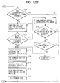
- Fig. 12 is comprised of Figs. 12A and 12B showing flowcharts which shows the control of a complementary recording in accordance with the present invention.
- Fig. 13 is a flowchart which shows the control of a complementary recording in accordance with the present invention.
- Fig. 14 is a view which shows the structure of a printing apparatus to which the present invention is applicable.
- Fig. 15 is a view which schematically shows a structural example of a head and ink system.
- Fig. 16 is a view which schematically shows a structural example of recovery means in accordance with the present embodiment including wiping means and cleaning means.
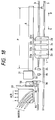
- Fig. 17 is a view which shows a structural example of wiping means.
- Fig. 18 is a plan view which schematically shows the structure of cleaning means in the vicinity of the home position of the recording head.
- Fig. 19 is a flowchart which shows the example of a printing sequence.
- Hereinafter, with reference to the accompanying drawings, the present invention will be described in detail.
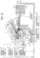
- Fig. 14 shows a structural example of an ink jet printing apparatus serving as a liquid discharging apparatus to which the present invention is applicable.
- In Fig. 14, a
carriage 1 mounts on it printingheads Guide shafts 3 support and guide thecarriage 1 movably.Reference numerals - A part of an endless belt 4 is connected to the
carriage 1. Thecarriage 1 is driven by a drivingmotor 5, a pulse motor driven by amotor driver 23, through the belt 4, and travels on theguide shafts 3 along the printing surface of a paper, OHP film, cloth or other printing medium (hereinafter referred to as a printing sheet) 6. Further, there are provided afeed roller 7 to feed theprinting sheet 6, guiderollers printing sheet 6, and afeed motor 9 to feed the printing sheet. - Also, a
liquid path 10 is provided for each of the printing heads 2a, 2b, 2c, and 2d to discharge ink droplets toward theprinting sheet 6. To eachink path 10, ink is supplied from each of theink tanks supply tubes liquid paths 10 to generate energy to be utilized for discharging ink, ink discharge signals are selectively applied from each of thehead drivers - Further, for each of the printing heads 2a, 2b, 2c, and 2d, the
head heaters 14a, 14b, 14c, and 14d (14b, 14c, and 14d are not shown in Fig. 14) andtemperature detecting means 15a, 15b, 15c, and 15d (15b, 15c, and 15d are not shown in Fig. 14) are arranged, respectively. The detection signals from thetemperature detecting means 15a, 15b, 15c, and 15d are inputted into acontrol circuit 16 provided with a CPU. Thecontrol circuit 16 controls the heating conditions of thehead heaters 14a, 14b, 14c, and 14d through a power-supply 18 in accordance with these signals. - Capping means 20 abuts upon the discharge port surface of each of the printing heads 2a, 2b, 2c, and 2d at the time of no printing. When printing is out of operation, the printing heads 2a, 2b, 2c, and 2d travel to the position facing the capping means 20. At this juncture, the capping means 20 is driven by a
cap driver 25 to advance forwardly so that itselastic member 44 is pressed to be in contact closely with the discharge port surface to complete capping. - When the printing head is left intact in the air for a long time, the moisture in ink is evaporated to make the ink overly viscous in the nozzles. As a result, discharging becomes unstable. In order to prevent this condition, the nozzle unit is cut off from the air and closed airtightly (being capped) when the nozzle unit is not in printing operation. In the cap unit, an absorbent is provided and kept in a wetting condition by ink so as to minimize the over viscosity of ink by maintaining the interior of the cap unit in high humidity.
- Also, if the capping condition is left intact for a long time, recovery process is executed by exerting pressure on ink. In other words, if this condition is left intact for a long time, ink in the interior of the discharge ports is gradually evaporated even when capped, and it becomes overly viscous. Also, air bubbles may be caused to reside in the interior of the discharge ports, thus hindering stable discharge in some cases. Therefore, when starting a printing, a pump provided for the ink tank is driven to pressurize ink so as to exhaust the overly viscous ink and remaining air bubbles in the interior of the discharge ports to the outside of the discharge ports. In this way, even if dust particles and fluffs adhere to the discharge port surface or dust particles and others enter the interior of the discharge ports, it is possible to effectively rinse them out for the maintenance of stable discharging.
- Means 31 for preventing clogging is to receive discharged ink when the printing heads 2a, 2b, 2c, and 2d operate idle discharging (that is, predischarging). This means 31 for preventing clogging faces the printing heads 2a, 2b, 2c, and 2d. It is provided with a
member 32 to receive liquid serving as the liquid receptacle that absorbs idly discharged ink, and arranged between capping means 20 and the start position of printing. In this respect, spongy porous material, sintered plastic material, or the like is effectively used for theliquid receiving member 32 andliquid retaining member 45. - Also, the idle discharge is not aimed at printing itself, but is to effectuate the temperature assurance of the area whose temperature is lowered due to the discharging flows of fluid and gas, as well as to remove unwanted substances in the discharge ports. Also, beside them, the idle discharge provides given driving pulses before the start of printing, so that ink is discharged from the entire discharge ports toward the cap unit and the like (that is, to carry out an aging operation). Here, if necessary, an idle discharge is performed while in capping in order to enhance the wetting condition in the atmosphere surrounding the discharge ports.
- To cleaning means 50, a rinsing
electromagnetic valve 51 and asuction pump driver 52 are connected. Under the control of acontrol circuit 16, rinsing solution is discharged from means 53 for wiping and rising, and rinsing solution is sucked from cleaning means 50, respectively. - Fig. 15 shows a structural example of a liquid discharge head. In Fig. 15, a
reference numeral 2 designates the discharge head; 22, its discharge surface; 101B, a nozzle unit in which a plurality of liquid paths are arranged in parallel in the vertical direction, and also, elements for generating discharge energy, such as electrothermal transducing elements, are arranged; 101C, a common ink chamber to supply ink to each of the liquid paths, which is connected to anink tank 110 throughsupply tubes supply tubes 104, agear pump 105 is provided to press ink to flow in the ink supply system of theprinting head 2 for the execution of ink exhaustion from the discharge ports or to execute an ink refreshing process (hereinafter referred to as a pressurized circulating process) by circulating ink in theink supply tubes ink chamber 101C when air bubbles and dust particles mixed in the supply paths andnozzle unit 101B are to be removed or any discharge recovery process is executed to remove the overly viscous ink or the like. - Fig. 16 and Fig. 17 are views showing a structural example of cleaning means 50. Here, Fig. 16 is a view which illustrates the cleaning means 50 observed from the main scanning direction of the
head 2. Fig. 17 is a view which illustrates a cleaningmember 70 and thehead 2, which are observed from above. In the present embodiment, the cleaningmember 70 serving as wiping means is formed by a flexible porous element. As the material of the cleaning member, it is possible to use polymeric porous element. When a polymeric porous element is used therefor, it is preferable to use a kind that does not make changes in volume when it absorbs ink, and not the one that changes its volume conspicuously when absorbing ink mist like polymeric foaming element. For example, it may be able to cite an element formed by formal foam resin as a suitable element in this respect. - Also, as an ink absorbent to be used here, a thermally sintered type polymeric porous element can be utilized. For example, it may be able to cite a thermally sintered low concentration polyethylene, high concentration polyethylene, polymeric polyethylene, compound polyethylene, polypropylene, polymethyl methacrylate, polystyrene, acrylonitrile copolymer, ethylene vinyl acetate copolymer, fluororesin, phenolic resin, or the like. Of these elements, preference is given to those using low concentration polyethylene, high concentration polyethylene, polymeric polyethylene, or polypropylene in consideration of the required capability of absorption of and resistance to ink.
- A
reference numeral 71 designates a holder to fix the cleaningmember 70 by pinching it with a fixingboard holder 71, anaperture 71B is arranged on thesurface 71A that abuts upon the cleaningmember 71, and then, the structure is arranged to connect the holder and asuction tube 74 through a communicatingpath 71C so that rinsing solution and ink absorbed by the cleaningmember 70 are exhausted by a suction means 82 in the direction indicated by an arrow A. This suction means 82 may be replaced by means for exhausting rinsing solution from the cleaning member with the formation of path to exhaust fluid by connecting a porous member or fabric member to the cleaningmember 70. - After rinsing by sucking the rinsing solution, the amount of rinsing solution remaining in the cleaning
member 70 is reduced appropriately, thus restoring the capability to absorb ink, foreign particles, or the like. In this way, it is possible to enhance the cleaning effects of the discharge port surface of thehead 2. Also, the leading end 70A of the cleaningmember 70 is overlapped with thedischarge surface 22 of thedischarge head 2 by a length designated by the letter L. It is then arranged to wipe thedischarge surface 22 of thehead 2 by use of this overlapped portion when thehead 2 scans. - A
reference numeral 75 designates a nozzle for supplying rinsing solution. By means of opening or closing anelectromagnetic valve 79, rinsingsolution 81 is supplied from atank 80 serving as means for supplying rinsing solution in the direction indicated by an arrow B through itssupply tube 76. Thus the structure is arranged to supply the rinsing solution from the nozzle of thedischarge unit 75A downwardly toward the cleaningmember 70 for its cleaning operation. - A
reference numeral 77 designates a receiving tray arranged below the cleaningmember 70. The structure is arranged to use this tray to receive the rinsing solution, which is not absorbed by the cleaningmember 70, but drops together with ink and foreign particles adhering to the cleaningmember 70 as the rinsing solution is being supplied from thesupply nozzle 75. Areference numeral 78 designates an exhaust tube to exhaust the rinsing solution received by the receivingtray 77 to an exhaust unit (not shown) in the direction indicated by an arrow C. - Now, the operation of the ink jet recording apparatus will be described hereunder. In Fig. 18, a printing
start detection sensor 34 and a capping meansdetection sensor 36 detect that each of the printing heads 2a, 2b, 2c, and 2d is in the given capping position. Asensor 35 for detecting idle discharge position detects the standard position of the idle discharge operation that the printing heads 2a, 2b, 2c, and 2d perform while traveling in the main scanning direction. - Fig. 19 is a flowchart showing the operational sequence of the technique on the assumption of which the structure described above is arranged in accordance with the present invention. At first, on the standby, each of the discharge surfaces 22a, 22b, 22c, and 22d of the printing heads 2a, 2b, 2c, and 2d is capped by capping
means 20. When printing signals are received by thecontrol circuit 16, a pressurized ink circulation starts (step S1). Then the head caps are released (step S2). - A recovery by means of the pressurized ink circulation and rinsing by means of the cleaning
member 70 are performed simultaneously (step S3). - Then, in step S4, the rinsing solution is sucked, thus reducing the remaining amount of rinsing solution in the cleaning
member 70 appropriately. As a result, the capability of absorbing and collecting ink and foreign particles is enhanced to increase the cleaning effects provided by the cleaningmember 70. Also, to suck rinsing solution, it is possible to create the negative pressure in the porous element serving as the cleaningmember 70 by the application of capillary phenomenon. By making this negative pressure greater than that in the nozzles of the liquid discharge heads, ink is drawn out from each of the nozzles at the time of cleaning. Therefore, it is possible to prevent the rinsing solution from entering the liquid chamber. Further, the capability of ink absorption is created in the interior of the nozzles, hence making it possible to demonstrate a dual effect that overly viscous ink is removed in the nozzles at the same time. - Then, from the
motor driver 23, driving signals are transmitted. The driving force of the drivingmotor 5 is transmitted to thecarriage 1 through the belt 4, thus thecarriage 1 is being driven to cause the heads to reciprocate. Then, when thecarriage 1 passes cleaning means 50, the cleaningmember 70 wipes the discharge surfaces 22 one after another for cleaning (step S5). In this respect, the wiping is meant the present embodiment to define wiping and cleaning the rinsing solution, ink, foreign particles, and the like on each discharge surface. - Now, ink droplets are being discharged while the discharge heads travel from the printing start detection position Po detected by the printing
start detection sensor 34 in the direction indicated by an arrow D, thus performing an image printing on the print width portion P on a printing sheet 6 (step S6). - At the same time, the cleaning member is rinsed (step S7), and then, the rinsing solution is sucked (step S8) to recover the cleaning capability of the cleaning member. After that, the
carriage 1 is reversed, and driven in the direction indicated by an arrow E to perform a predischarging operation while passing the predischarging position (step S9). Here, the predischarge is executed for theliquid receiving member 32. Theprinting sheet 6 is then fed by the width P of the print portion in the direction indicated by an arrow F. - Subsequently, when the image printing continues (that is, a case where step S10 is found to be negative) and n line printing has not been terminated (that is, a case where step S11 is found to be negative), the process will return to the step S5 to cause the
carriage 1 to reciprocate, and then, as shown in Fig. 7, a cleaning is executed by reciprocation (step S5). At this juncture, in the forward operation, the wiping surface 70B of the cleaning member is wiped. Therefore, the wiping surface 70C that is once stained does not wipe thedischarge surface 22. This arrangement produces no adverse effect on cleaning, rather it enhances the cleaning effect as much as two times. - On the other hand, when the image printing is terminated (that is, the step S10 is found to be affirmative) and the n line printing is terminated (that is, the step S11 is found to be affirmative), the
discharge surface 22 of theheads 2 is capped by cappingmeans 20 to be airtightly closed (steps S12 and S13). - Hereinafter, the description will be made of a first embodiment in accordance with the present invention.
- Figs. 1A to 1G are views which show the features of the present invention. At first, as shown in Fig. 1A, detection is made preceding a printing to determine whether or not any abnormal nozzle exists in the
printing head 1 provided with multinozzles formed by a plurality of nozzle arrangements. The abnormal nozzle means the nozzle whose discharge is disabled, the so-called "twisted nozzle", the nozzle that prints dots in an excessively large or small size, or the like. Hereinafter, it is collectively called "non-discharge nozzle". - In Fig. 1A, the non-discharge nozzle or nozzle group is designated by a
reference numeral 202 in the nozzle group of theprinting head 201. Also, areference numeral 203 in Fig. 1A designates the area to be printed by theprinting head 201. - Now, as shown in Fig. 1B, image data are removed with respect to a non-discharge nozzle (per nozzle) or
non-discharge nozzle group 202, which is detected by the detection process described above, and then, that particular line is printed. As the result of printing, the portion of the scanned image, which corresponds to the non-discharge nozzle or nozzle group, appears as a white streak as shown in Fig. 1C. - Then, as shown in Fig. 1D, a sub-scanning feed is executed in the
sub-scanning direction 227 by the width of the white streak, that is, a width corresponding to the non-discharge nozzle (or non-discharge nozzle group) 202, thus allowing a nozzle (or group) in a good discharging condition to face the white streak portion. The amount of the sub-scanning feed is not necessarily confined thereto. It should be good enough if only the head is arranged to face a position where it can record with a good nozzle (or group) with respect to the area that has not been recorded by the last main scan. - Then, as shown in Fig. 1E, at the time of returning scan of the recording head, the white streak portion is printed complementarily by use of a good nozzle or nozzle group with respect to the part of image data that has not been printed by the last main scan. Consequently, as shown in Fig. 1F, an image is formed without any defects. Thereafter, as shown in Fig. 1G, the sub-scanning feed is executed so that recording is made in the next recording area. Then the aforesaid operation will be repeated.
- As described above, in the main scan, a recording is performed by good nozzles excluding non-discharge nozzles, and then, a sub-scanning feed is executed so that the area that has not been recorded can be recorded by use of good nozzles. Subsequently, a complementary recording is executed in the returning scan of the recording head. In this way, it is possible to obtain an image without defects even by the recording head having some abnormal nozzles such as causing non-discharge.
- Also, there is no need for providing any special head for use of complementary recording, nor there is any possibility that the structure of the recording apparatus itself is made more complicated. Further, it is possible to obtain a good image without reducing the recording speed just by executing a sub-scanning feed for a slight amount preceding the returning operation of the recording head.
- Now, a second embodiment will be described in accordance with the present invention.
- Figs. 2A and 2B show cases where a non-discharge nozzle (or non-discharge nozzle group) occurs on the end portion of the downstream side in the sub-scanning direction among a plurality of nozzles of a recording head.
- When a non-discharge nozzle or group occurs on the end portion of the downstream side like this, it is possible to obtain an image without defects as shown in Fig. 2A by printing on the width of one line in the main scan without using the abnormal nozzles after making the printing width narrower to the extent that the non-discharge nozzles are generated. Then, in order to print on the area that has not been printed due to the occurrence of the non-discharge nozzle or group, a sub-scanning feed is performed in the direction 227' opposite to the
sub-scanning feed direction 227 as shown in Fig. 2B, thus enabling a good nozzle or group to face such area. In this way, a complementary printing is performed in the returning operation of the recording head with respect to the area that has not been recorded due to the non-discharge nozzle or group as in the first embodiment. - As described above, in the main scan, a recording is performed by
good nozzles 203 excluding non-discharge nozzles, and then, a sub-scanning feed is made executable both in the regular and opposite directions so that the area that has not been recorded can be recorded by use of good nozzles. Subsequently, a complementary recording is executed in the returning scan of the recording head. In this way, it is possible to obtain an image without defects even by the recording head having some abnormal nozzles such as causing non-discharge. - Also, there is no need for providing any special head for use of complementary recording, nor there is any possibility that the structure of the recording apparatus itself is made more complicated. Further, it is possible to obtain a good image without reducing the recording speed just by executing a sub-scanning feed for a slight amount preceding the returning operation of the recording head.
- Figs. 3A aned 3B show cases where a non-discharge nozzle (or non-discharge nozzle group) occurs on both ends of a head among a plurality of nozzles of the recording head.
- When a non-discharge nozzle or group occurs on both ends of the head like this, a printing is performed by reducing the printing width of only the non-discharge nozzle (or group) on the downstream end in the direction of the sub-scanning feed as shown in Fig. 3A. Then, as shown in Fig. 3B, a complementary printing is performed in the returning scan of the head by use of a good nozzle or group with respect to the margin on the upstream end, which has not been recorded in the main scan.
- In the present embodiment, the sub-scanning feed in recording represented in Fig. 3B is performed in the regular direction. However, as described in the second embodiment, it may be possible to execute the sub-scanning feed in the opposite direction so that the recording can be performed by a good nozzle or group with respect to the area that has not been recorded due to the non-discharge nozzle or group. In consideration of the feed amount in the sub-scanning direction that will be required subsequent to a complementary recording, the sub-scanning feed preceding the returning scan should be performed in the regular direction. Then the sub-scanning amount preceding the main scanning recording is made smaller, thus contributing to the enhancement of the throughput. Also, it may be possible to change the directions of sub-scans preceding the complementary recording in accordance with the number of non-discharge nozzles in a group. Further, by setting the directions of sub-scans alternately preceding the complementary recording, it is possible to make the frequencies of nozzle use uniform for the recording head, thus contributing to the longer life of the recording head.
- As described above, it is possible to obtain, as in the previous embodiment, a good image without defects even by the recording head having some abnormal nozzles such as causing non-discharge.
- Also, there is no need for providing any special head for use of complementary recording, nor there is any possibility that the structure of the recording apparatus itself is made more complicated. Further, it is possible to obtain a good image without reducing the recording speed just by executing a sub-scanning feed for a slight amount preceding the returning operation of the recording head.
- Figs. 4A and 4B show cases where plural numbers of non-discharge nozzles (or non-discharge nozzle groups) 202 and 202' occur for a head among a plurality of nozzles of the recording head.
- When plural non-discharge nozzles (or groups) occur, a recording is performed excluding non-discharge nozzles (or groups) as shown in Fig. 4A in the same way as described in the previous embodiment. Then, as shown in Fig. 4B, a sub-scanning feed is executed so that the areas that have not been recorded but appear as white streaks can be recorded by
good nozzles 203 and 203', thus executing a complementary recording in order to obtain a good image without defects. - In some cases, however, there occurs difficulty in obtaining a perfect image having no defects just by the complementary recording as in the previous embodiment.
- Fig. 5 shows a state where non-discharges take place with respect to plural nozzles (or nozzle groups) among a plurality of nozzles of a recording head. In Fig. 5, the positions of nozzles (or nozzle groups) presenting malfunction such as non-discharge are particularly complicated. In Fig. 5, a
reference numeral 205a designates the relative position between a recording head and recording medium when performing a main scanning recording; also, 205b, the relative position of the recording head when a sub-scanning feed is executed for the maximum width portion of white streaks appearing due to non-recording caused by the non-discharge nozzles (or groups). As shown in Fig. 5, when non-discharge nozzles (or groups) occur, it should be difficult to perform the complementary recording perfectly just by the sub-scanning feed for the maximum width of non-discharge nozzles in some cases. In that case, a sub-scanning feed is further executed in the relative position such as indicated at 205b with respect to the portion that overlaps with the non-recordable area resulting from the occurrence of the non-discharge nozzles. Then, by shifting the recording head to a relative position such as indicated at 205c, it becomes possible to obtain an image without defects. Even if plural non-discharge nozzles (or non-discharge nozzle groups) occur as described above, it is possible to obtain a good image without defects by executing the sub-scanning feed to the position where a complementary recording is possible on the white streaks by use of the good nozzles of the recording head subsequent to the main scanning recording. - Fig. 6 shows a case that non-discharge nozzles of a recording head occur in a position where it is made more difficult to execute the complementary recording than in Fig. 5.
- As in the example shown in Fig. 5, a sub-scanning feed is executed for the maximum width portion of the white streaks caused by non-discharge nozzles (or groups). Then, assuming that the relative position is now made such as indicated at 206b, there still exists the area where non-recordable portions are overlapped because of the non-discharge nozzles. Consequently, another sub-scanning feed is assumed to have been executed for an amount so that the relative position becomes as indicated at 206c. Then, it appears that the area of the white streak on the downstream end is left unrecordable. In this case, it is determined that no complementary recording is possible for the non-discharge nozzles thus generated, and a warning is issued accordingly. Thus the operation of the apparatus is suspended.
- Also, if it is difficult to suspend the operation of the apparatus immediately while in recording or the like, an arrangement may be made so that the complementary recording is executed by plural scans with respect to the area that has not been recorded because of the plural nozzles causing non-discharge. In this case, although the recording speed is lowered inevitably, it is possible to obtain a good and sound image without suspending the operation of the apparatus.
- Fig. 7 is a view which schematically shows a direct printing apparatus to which the present invention is applicable. Also, Fig. 8 is a perspective view schematically showing its printing unit.
- Hereinafter, with reference to Figs. 7 and 8, the detailed description will be made of a recording apparatus applicable to each of the embodiments described above, an apparatus for detecting non-discharge nozzles, and the control of the non-discharge detection to the execution of the complementary recording with respect to the non-discharge nozzles thus detected.
- The rolled ink
jet recording sheet 211 set in the lower part of the apparatus main body shown in Fig. 7 is carried to aprinting unit 215 by aguide roller 212 and afeed roller 213 through acutter 214, which cuts the sheet in an appropriate length. The recording sheet is exhausted to the outside from theexhaust sheet port 216 after being printed by means of theprinting unit 215. - Now, in conjunction with Fig. 8, the
printing unit 215 will be described in detail. - A
printing head array 217 comprises a plurality of heads to print in plural colors. The color printing heads comprise seven heads, Bk for printing in black, C1 in cyan, C2 in cyanic special color, M1 in magenta, M2 in magenta special color, O in orange special color, and Y in yellow each. Here, special colors mean those colors that cannot be obtained easily by mixing the conventional four colors (Bk, Y, M, and C). With these special colors, it is possible to clearly reproduce colors hardly obtainable by mixing colors on an image to be recorded, and to provide a wider range for colors to be reproduced at the same time. Thishead array 217 is mounted integrally with thescanning carriage 218 linearly guided byrails 231. - The
head array 217 travels forwardly (main scan) in the direction indicated by an arrow 226 (main scanning direction) in Fig. 8 while printing from the left end to the right, and then, returns to the left side. When one line is printed, theprinting sheet 211 is fed (sub-scanned) in the direction indicated by an arrow 227 (in the sub-scanning direction) by the printing width for the execution of printing on the next line. - In Figs. 8 and 9, a
reference numeral 219 designates a sheet for detecting malfunction to confirm and detect the generation of non-discharge nozzles. Its feed driving is arranged separately from that of theprinting sheet 211. Thepattern 220 for detecting malfunction is such that each color is printed in a density of almost 100% duty to make it easy to detect any malfunction, and is arranged to be transferred intermittently for the detection of malfunction as described later. Thesheet 219 for detecting malfunction is supplied from a feedingroller 223 to a windingroller 224 shown in Fig. 7. - As shown in Fig. 9, the
printing sheet 211 is fed in the sub-scanning direction (indicated by an arrow 227) precisely at a pitch of the printing width w' so that the printing of each line is continuously performed. - As an apparatus for detecting abnormal nozzles to detect non-discharge nozzles, it is possible to adopt the one disclosed in detail by the applicant hereof in Japanese Patent Laid-Open Application No. 6-79956.
- The apparatus for detecting abnormal nozzles disclosed in Japanese Patent Laid-Open Application No. 6-79956 demonstrates a sufficient ability as an apparatus for detecting non-discharge nozzles. In accordance with this apparatus, each individual dot is detected to determine the non-discharge, the twisted discharge, and the discharge of excessively large or small dots of each nozzle. Therefore, even when there are many nozzles that malfunction, it is possible to maintain the complementary function for a long time because, with this detection, the overlapping probability between the white streak portion caused by non-recording in the main scan and the abnormal nozzles becomes smaller when executing the complementary recording.
- Here, in the present invention, it is possible to provide a method of detecting abnormal nozzles with a simpler structure. Now, in conjunction with Figs. 8, 9 and 10, its detail will be described.
- An
apparatus 221 for detecting abnormal nozzles is positioned to face thedetection sheet 219. In order to read the detection patterns in the respective colors (the patterns recorded by the recording heads Bk, C1, M1, and others as shown in Fig. 9), itsreading center 222 is positioned on the moving line of patterns in each color. Each of the reading devices comprises a pair oflamp 223 andoptical sensor 224 as shown in Fig. 10. Also, its width in the vertical direction is made narrower so as to detect non-discharge nozzles, while the structure is arranged to enable the width in the main scanning direction to perform a wider reading in order to average the dot variation from the same nozzle. In this respect, the width in the vertical direction is not necessarily arranged so narrow as to discriminate recording per individual nozzle. - As described above, the detection pattern passes the front end of the fixed
reading device 221 in the direction indicated by anarrow 228 as shown in Fig. 9 and Fig. 10 to allow its density to be read for the detection of abnormal nozzles. - Fig. 11 shows the output of reading by the optical sensor, in which a
reference numeral 231 designates the nozzle or nozzles that generate non-discharging. As compared to thereading area 225, thenon-discharge portion 231 is minute, but in itsoutput 232, the correspondingportion 233 appears. In order to determine any non-discharges, acertain level 234 is defined. The portion whose output is greater than such level in reading (the reflected light from the detection pattern is intensified) is assumed to be an area where non-discharge nozzle group exists. Although it is difficult to detect a nozzle (a single nozzle) that actually generates non-discharge from the result of this reading for detection, it is still possible to adopt this detection for executing a complementary recording by accepting it as a finding that a non-discharge nozzle or nozzles are included in a portion of several nozzles before and after such a minute area thus read out for detection. Also, it is possible to detect the nozzle or nozzles that actually generate non-discharge by use of a sensor capable of providing a highly precise result of detection. - The detection pattern is printed by the entire nozzles (in a width W), but the width of one line to be actually printed is a portion (whose width is W') where the corresponding output of nozzles, which are positioned on both ends of the nozzle array is in the so-called "drooping shoulder" area, is excluded. However, it is still arranged to be able to detect any non-discharge that may occurs on the ends of this width W' of the actually printing. Here, although the exact detection cannot be carried out with respect to several nozzles on both ends, it is possible to materialize the apparatus for detecting non-discharges extremely easily. Moreover, the non-discharge nozzles can be specified immediately just by one-time scan of an optical sensor. Therefore, it is possible to shorten the time required to carry out reading to detect the occurrence of non-discharges, and remove the corresponding data, hence preventing the dropdown of printing speed or the like for the provision of an apparatus whose cost performance is excellent.
- Also, in the structure of the apparatus for detecting abnormal nozzles described above, it is also possible to detect non-discharge nozzles on the end portions of the nozzle array of the recording head by combining the recording and sub-scans to form detection patterns in succession in the sub-scanning direction, and by detecting each junction between them arranged in such a way.
- Now, Figs. 12A, 12B and Fig. 13 are flowcharts showing the control required in this respect.
- At first, in step S101, printing is started. Then, in step S102, the detection pattern is printed. In Fig. 8, the carriage advances once from the home position 218' to a position at 218''. Then, the detection pattern formed by each color is printed on the
detection sheet 219 when the carriage returns to the home position 218'. When the detection pattern is printed, the detection sheet is fed immediately in the direction indicated by anarrow 228. In step S103, the output of reading is obtained as shown in Fig. 11. Then, in step S104, the position and width of non-discharge nozzles are determined per color from the output of reading thus obtained. If it is found that there is no nozzle that has generated non-discharge, the process will proceed to step S118 to execute the usual printing. In the step S104, if any non-discharge nozzles are detected, it is determined in the next step S106 whether or not the non-discharge nozzles are positioned on the downstream end of the head. If negative, a sub-scanning feed is executed in the next step S107 for the maximum width of the non-discharge nozzles thus detected. Then, in step S108, it is determined whether or not the white streak recorded in the image by the main scan is overlapped with the non-discharge nozzles when executing the complementary printing in the returning scan. If no overlapping is found in the step S108, the decision is made on the portion in the nozzle array where the printing data to be removed, as well as the maximum width portion of the detected non-discharge nozzle (or group) to be defined for the amount of sub-scanning feed for the intended complimentary printing. Thereafter, the recording in the main scan, sub-scanning feed, and complementary recording in the returning scan are performed in accordance with the conditions thus decided. - After the complementary recording, a sub-scanning feed is performed for an amount, which is arrived at by subtracting the amount of sub-scanning feed preceding the complementary printing from feeding width of the printing sheet for one-line portion, and then, the printing on the next line is prepared. In step S105, it is determined whether or not any printing is performed on the next line.
- Also, in step S108, if it is found that the white streak portion and the non-discharge nozzles are overlapped, a sub-scanning feed is assumed to be executed for the amount corresponding to such overlapped portion. Then, it is further determined whether or not the white streak that has not been recorded in the last scan overlaps with the non-discharge nozzles. If no overlapping is found, detection is made with respect to the downstream end side of the nozzles. If there is no problem in the relative position currently existing between the recording head and recording area, a sub-scanning feed for the complementary printing is defined accordingly, and thereafter, the printing and complementary printing will be performed as described earlier.
- In step S110 or step S111, if it is determined that any complementary process cannot be carried out exactly, a warning is indicated in step S112, and the operation of the apparatus is suspended.
- Also, in step S106, if any non-discharge nozzles are detected on the downstream end side of the nozzle array of the recording head, it is assumed as if such nozzles exist, and then, the printing is executed by reducing the printing width of the line to that extent. In step S121 and thereafter, printing and complementary printing are executed in the same manner as described above.
- The sub-scanning feed for the complementary recording has been described as being performed in the regular direction in order to determine whether or not the white streak caused by the non-discharge nozzles in the recorded image is overlapped with the area of the non-discharge nozzles in executing the complementary recording. However, it is also possible to perform such sub-scanning feed in the opposite direction, and then, use a method for working out an appropriate amount of the sub-scan, or to combine them for attaining the objective.
- In the aforesaid control flow, the description has been made of a head using one color, but in the case of a full color printing apparatus provided with heads using plural colors, the detection patterns for all the colors are examined to determine whether or not the maximum width of non-discharge nozzles among those having been examined does not present any unfavorable problem with respect to the sub-scanning feed for the complementary operation, and also, to decide on the amount of the sub-scanning feed that may allow the execution of the complementary recording appropriately, thus arranging an appropriate sub-scanning amount for each of the heads preceding the complementary recording.
- The structure of detecting abnormal nozzles, which has been described above, is applicable to each of the aforesaid embodiments. Here, using a simply structured detection apparatus, it is possible to appropriately complement the degradation caused by non-discharge nozzles for an image to be recorded.
- In the embodiments described above, the nozzles that causes malfunction such as non-discharge are detected optically using printing patterns. However, the present invention is not necessarily limited thereto. It may be possible to apply a structure in which the breakdown of discharge heaters is detected. The detection of discharge heater breakdown may be possible by conducting resistance check between the discharge pulses to be applied to printing in accordance with the image data. In this way, it is possible to detect whether or not there is any breakdown of the discharge heaters.
- If the heater breakdown detection is used together with the detection method described above, not only it is possible to detect non-discharge nozzles exactly, but also, detect the position where malfunction takes place even when the malfunction occurs while a given line is being printed. Therefore, if only a complementary operation is performed accordingly, it is possible to obtain a recorded image without defect by executing an appropriate complementary recording.
- Also, in each of the embodiments described above, the complementary recording is performed in the returning operation of the printing head, but it may be possible to arrange the structure so that a main scan is again executed for the complementary recording after the printing head is once returned to its home position side. In this way, the intended complementary recording is completely performed. In this case, although the printing speed is lowered, there is no need for any operation to read out the data reversely in order to perform the returning scan in agreement with the forward scan. Moreover, the superposing order of each color at the time of color recording becomes the same as that of the good nozzles. Therefore, the tone of color dots to be recorded by the complementary recording becomes the same as that of other dots, thus making it possible to execute the complementary recording in a better condition for the defective portion caused by non-discharge nozzles. Also, in consideration of the expected slowdown of the printing speed, it may be possible to arrange a structure so that the user can select arbitrarily whether the complementary recording for non-discharge nozzles is executed in the returning operation of the head or the complementary operation is made by performing the main scan again.
- In this respect, if an ink jet printing method is adopted for embodying the present invention, it is possible to obtain significant effects. Of the ink jet printing methods, it is possible to demonstrate particularly excellent effects by the application of a method having means for generating thermal energy to be utilized as energy for discharging ink, which is capable of changing states of ink when the thermal energy is applied. In other words, the adoption of printing head and apparatus using the bubble jet method advocated by Canon Inc contributes to obtaining still better results. With the application of a method of the kind, printing is possible in a higher density and precision.
- Regarding the typical structure and operational principle of such method, it is preferable to adopt those which can be implemented using the fundamental principle disclosed in the specifications of U.S. Patent Nos. 4,723,129 and 4,740,796. This method is applicable to the so-called on-demand type printing system and a continuous type printing system as well. Particularly, however, the method is suitable for the on-demand type because the principle is such that at least one driving signal, which provides a rapid temperature rise beyond a departure from nucleation boiling point in response to printing information, is applicable to an electrothermal transducer disposed on a liquid (ink) retaining sheet or liquid passage whereby to cause the electrothermal transducer to generate thermal energy to produce film boiling on the thermoactive portion of printing head, thus effectively leading to the resultant formation of a bubble in the liquid (ink) one to one for each of the driving signals. By the development and contraction of the bubble, the liquid (ink) is discharged through a discharging port to produce at least one droplet. The driving signal is more preferably in the form of pulses because the development and contraction of the bubble can be effectuated instantaneously, and, therefore, the liquid (ink) is discharged with quick response. The driving signal in the form of pulses is preferably such as disclosed in the specifications of U.S. Patent Nos. 4,463,359 and 4,345,262. In this respect, the temperature increasing rate of the heating surface is preferably such as disclosed in the specification of U.S. Patent No. 4,313,124 for an excellent printing in a better condition.
- The structure of the printing head may be as shown in each of the above-mentioned specifications wherein the structure is arranged to combine the discharging ports, liquid passages, and the electrothermal transducers (linear type liquid passages or right-angled liquid passages). Besides, the structure such as disclosed in the specifications of U.S. Patent Nos. 4,558,333 and 4,459,600 wherein the thermal activation portions are arranged in a curved area is also included in the present invention. In addition, the present invention is effectively applicable to the structure disclosed in Japanese Laid-Open Application No. 59-123670 wherein a common slit is used as the discharging ports for plural electrothermal transducers, and to the structure disclosed in Japanese Patent Laid-Open Application No. 59-138461 wherein an aperture for absorbing pressure wave of the thermal energy is formed corresponding to the discharge ports.
- In addition, it is of course possible to structure the printing head in accordance with the mode of a printing apparatus. With respect to the mode of the so-called line printer, it should be good enough if the printing head is structured so that its discharge ports are arranged over an area corresponding to the width of a printing medium. Also, for the printing head of a serial type as exemplified above, the present invention is effectively applicable to a printing head fixed to the apparatus main body or to an exchangeable chip type, which can be electrically connected with the apparatus main body and ink is supplied from the apparatus main body to the head when it is installed in the apparatus main body, or to the printing head of a cartridge type in which an ink tank is formed together with the printing head itself.
- Also, for the present invention, it is preferable to additionally provide a printing head with recovery means and preliminarily auxiliary means as constituents of the printing apparatus because these additional means will contribute to making the effectiveness of the present invention more stabilized. To name them specifically, these are capping means for the printing head, cleaning means, compression or suction means, preliminary heating means using electrothermal transducing elements or heating elements other than these transducing elements or combination of both elements, and predischarge means for executing discharges other than those for printing.
- Also, in the embodiments of the present invention described above, while the ink has been described as liquid, it may be an ink material which is solidified below the room temperature but liquefied at the room temperature. Since the ink is controlled within the temperature not lower than 30°C and not higher than 70°C to stabilize its viscosity for the provision of the stable discharge in general for an ink jet method, the ink may be such as to be liquefied when the applicable printing signals are given. In addition, it may be possible to adopt the use of ink having a nature of being liquefied only by the application of heat so as to positively prevent the temperature from rising due to the thermal energy by use of such energy as an energy to be consumed for changing states of ink from solid to liquid, or to prevent ink from being evaporated by use of the ink which will be solidified when left intact. In any case, it may be possible to apply to the present invention such ink having a nature to be liquified only by the application of thermal energy, such as the ink, which is capable of being discharged as ink liquid by enabling itself to be liquefied when the thermal energy is applied in accordance with printing signals, and the ink, which will have already begun solidifying itself by the time it reaches a printing medium. In this case, it may be possible to retain ink in the form of liquid or solid in the recesses or through holes of a porous sheet such as disclosed in Japanese Patent Laid-Open Application No. 54-56847 or No. 60-71260 in order to enable ink to face the electrothermal transducers. In the present invention, the most effective method adoptable for the various kinds of ink mentioned above is the one capable of implementing film boiling as described above.
- Further, as the mode of the present invention, it may be possible to adopt a copying apparatus combined with a reader or the like in addition to the image output terminal for a computer, or other information processing apparatus.
- Also, it is possible to apply the present invention widely to ink jet textile printing apparatuses for printing fabric by the application of the ink jet recording method. Compared to the conventional screen printing technique, the ink jet textile printing apparatus makes it possible to print fabric at higher speeds in accordance with printing data (such as images, characters, colors, or other information). The features of ink jet recording method are effectively utilized in this respect.
- Because of this special usage, that is, to print fabric, the aspect of industrial use should be more intensified. From this point of view, it is desirable to provide a higher speed, a lower cost, a longer life, and an easier maintenance. Here, by the application of the complementary recording technique of the present invention, it is possible to print images without defects continuously, thus demonstrating excellent effects in attaining higher speed and better cost performance.
- In this respect, the following properties are required for fabric to be printable by the application of the ink jet method:
- (1) The color of ink should come out in a sufficient density.
- (2) The degree of exhaustion of ink should be high.
- (3) Ink should dries quickly on the fabric.
- (4) Ink should not blur irregularly on the fabric.
- (5) The fabric should be easy to be carried in the apparatus.
- In order to satisfy these properties, it is possible for the present invention to preprocess the fabric as required. For example, in accordance with Japanese Patent Laid-Open Application No. 62-53492, there are disclosed fabric provided with a layer for receiving ink. Also, in Japanese Patent Publication No. 3-46589, it is proposed to provide the fabric in which reduction preventive agent or alkaline substance is contained. As an example of such preprocess, a treatment is made to enable these textiles to contain a substance selected from among alkaline substance, water soluble polymer, synthetic polymer, water soluble metallic salt, urea, and thiourea.
- The alkaline substance is, for example, sodium hydroxide, potassium hydroxide, or other sodium alkaline metals, mono-, di-, tri-ethanol amine or other amine group, sodium carbonate, sodium bicarbonate, or other carbonates, alkaline metallic bicarbonate salt or the like. Further, there can be named organic metallic salt such as calcium acetate, barium acetate, or ammonia and ammonia compound or the like. Also, it is possible to use the trichloro natrium acetate or the like that is transformed into alkaline substance by the application of steaming and drying heat. Particularly, preference is given to natrium carbonate and natrium bicarbonate as an alkaline substance, which is usable as a dye color of reactive pigment.
- As water soluble polymer, there can be named, for example, starch such as corn, wheat, cellulose substance such as carboxymethyl cellulose, methyl cellulose, hydroxyethyl cellulose, polysaccharide such as natrium alginic acid, arabian, loquasweet bean, tragacanth, guam rubbers, and tamarind seed, protein substance such as gelatin, casein, and water soluble natural polymer such as tannic substance and lignin substance.
- Also, as synthetic polymer, there can be named, for example, polyvinyl alcoholic compound, polyethylene oxide compound, alkali acid water soluble polymer, maleic anhydride water soluble polymer or the like. Of these substances, it is preferable to use poly-saccharide polymer or cellulose polymer.
- As water soluble metallic salt, there can be named, for example, alkali metals or a compound of pH4 to 10, which forms typical ionic crystals, such as halogenous compound of alkaline earth metals. As typical examples of such compounds, there can be named NaCl, Na₂SO₄, KCl and CH₃COONa, or the like. Also, as alkaline earth metals, CaCl₂ and MgCl₂ or the like. Of these substances, salt group such as Na, K and Ca are preferable.
- Methods are not particularly limited to enabling fabric to contain substance and others by means of a preprocess as described above, but it may be possible to name a usually performed dipping method, a padding method, a coating method, a spraying method, among others.
- Further, the textile printing ink, which is applicable to fabric for use of ink jet printing, is such as just adhering to the textiles when applied onto them for printing. Therefore, it is preferable to execute a fixing process so that the color pigments in ink such as dyes should be fixed to the textiles. For a fixing process of the kind, any one of known methods is usable. For example, a steaming method, an HT steaming method, or a thermofixing method can be named. If no alkali treatment is given to them in advance, there can be named an alkali pad steaming method, an alkali blotch steaming method, an alkali shock method, an alkali cold fixing method, among others. Also, for the fixing process, there are those which include a reaction process or do not include it depending on the dyes to be used. Among those which do not include this process, there are some examples in which the dyes are contained in the textures and do not allow them to be removed physically. Also, as ink, it is possible to use any one of them appropriately if only a required pigment is contained. It may also be possible to use the ink containing colors, not necessarily dyes.
- Further, in order to remove the dyes yet to be reacted and the substances used in the preprocess, rinsing may be applied in accordance with the conventionally know method after executing the reaction and fixing processes as described above. In this respect, it is preferable to perform the conventional fixing process together when this rinsing treatment is exercised.
- The printed articles that have been given the post process described above are cut in a desired size. Each of the pieces thus cut is given processes to make it a final product, such as sewing, bonding, welding, or the like, thus obtaining one piece, dress, necktie, swim suit or other clothing, or bed cover, sofa cover, handkerchief, curtain, or the like. The method for processing fabric to make it clothing or other daily necessities by means of sawing and others is a technique that is conventionally known.
- In this respect, as a printing medium, there can be named fabric, wall cloths, embroidery threads, wall papers, paper sheets, OHP films or the like. The fabric includes all the textiles, nonwoven textiles, and other cloths irrespective of materials, weaving methods, and netting methods.
- As described above, in accordance with the present invention, it is possible to obtain the result of discharges (recorded image) without defects as desired even when malfunction occurs in recording means of a recording apparatus, particularly when non-discharge or other malfunction occurs in discharging means of an apparatus for discharging liquid such as an ink jet recording apparatus.
- By the application of the present invention, a printing head having abnormal nozzles can be used as a "good" head. For example, even for a multinozzle head having as many nozzles as several hundreds to several thousands, its production yield is increased.
- Also, in a case where abnormal nozzles occur while the printing head is in use, a complementary recording is performed by detecting such abnormal nozzles. As a result, it is practically possible to prolong the life of the recording head remarkably.
- Moreover, it is possible to use an essentially inexpensive multinozzle head having several hundreds to several thousands of nozzles at costs essentially reduced, and to continuously operate it until its effective life terminates, while attempting the prolongation of the effective long life of the head. Therefore, it is possible to provide the ink jet printing technique with the productivity and economy in terms of its industrial application.
- Also, in accordance with the present invention, the complementary recording is executed in the returning operation of the recording head. Therefore, it is possible for the recording head to perform complementary operation for the abnormal nozzles without lowering the throughput. Further, there is no need for providing any head dedicated for use of the complementary operation other than the head used for usual printing. As a result, the complementary recording is attained without making the structure of the apparatus more complicated or larger.
Claims (21)
- A recording apparatus provided with a recording head having a plurality of recording elements arranged in it, main scanning means for enabling said head to execute its main scan relatively with respect to a recording medium, driving means for driving said head to form an image on said recording medium while said recording head performs its scans by said main scanning means, and sub-scanning means for enabling said recording head to perform its sub-scan with respect to said recording medium in the direction substantially rectangular to the scanning direction of said main scanning means, comprising:
means for controlling recording to perform a sub-scan by said sub-scanning means in an amount smaller than the length of recording elements arranged for said recording head subsequent to the recording scan performed by said main scanning means, and then, to perform a complementary recording by use of other recording elements in the returning operation of said recording head with respect to the recording area of the recording elements becoming incapable of recording in said main scanning. - A recording apparatus according to Claim 1, wherein said means for controlling recording performs recording by selecting only recordable recording elements among said plurality of recording elements while said recording head is in its main scan.
- A recording apparatus according to Claim 1, wherein said means for controlling recording sets the sub-scan by said sub-scanning means in an amount corresponding to the recording width of the incapable recording elements continuously positioned among said plurality of recording elements after said main scan for recording.
- A recording apparatus according to Claim 1, further comprising:
means for detecting malfunction in order to detect abnormal recording means becoming incapable of recording among said plurality of recording elements. - A recording apparatus according to Claim 4, wherein said means for detecting malfunction is capable of detecting a group of recording means comprising a plurality of recording means including abnormal recording means becoming incapable of recording, and said means for controlling recording performs recording by selecting recording elements excluding said group of recording means while said recording head performs its main scan by said main scanning means.
- A recording apparatus according to Claim 1, wherein at the time of the returning operation of said means for controlling recording after said main scan, the reading order is reversed with respect to the recording data related to the recording elements becoming incapable of recording in said main scan.
- A recording apparatus according to Claim 1, wherein said recording head is provided with discharge ports to discharge ink corresponding to said plurality of recording elements, and said recording elements are discharging means for discharging ink.
- A recording apparatus according to Claim 7, wherein said discharging means are electrothermal transducing elements to give thermal energy to ink, and cause ink to be discharged by creating change of states of ink by the application of heat caused by said thermal energy.
- A recording apparatus according to Claim 1, wherein said apparatus uses fabric as its recording medium.
- A recording apparatus provided with a recording head having a plurality of recording elements arranged in it, main scanning means for enabling said head to execute its main scan relatively with respect to a recording medium, driving means for driving said head to form an image on said recording medium while said recording head performs its scans by said main scanning means, and sub-scanning means for enabling said recording head to perform its sub-scan with respect to said recording medium in the direction substantially rectangular to the scanning direction of said main scanning means, comprising:
complementary recording means to perform a sub-scan by said sub-scanning means in an amount smaller than the length of recording elements arranged for said recording head subsequent to the recording scan performed by said main scanning means, and then, to perform a complementary recording by use of other recording elements in the returning operation of said recording head with respect to the recording area of the recording elements becoming incapable of recording in said main scanning. - A recording apparatus according to Claim 10, wherein said complementary recording means performs recording by selecting only recordable recording elements among said plurality of recording elements while said recording head is in its main scan.
- A recording apparatus according to Claim 10, wherein said complementary recording means sets the sub-scan by said sub-scanning means in an amount corresponding to the recording width of the incapable recording elements continuously positioned among said plurality of recording elements after said main scan for recording.
- A recording apparatus according to Claim 10, further comprising:
means for detecting malfunction in order to detect abnormal recording means becoming incapable of recording among said plurality of recording elements. - A recording apparatus according to Claim 10, wherein said recording head is provided with discharge ports to discharge ink corresponding to said plurality of recording elements, and said recording elements are discharging means for discharging ink.
- A recording apparatus according to Claim 14, wherein said discharging means are electrothermal transducing elements to give thermal energy to ink, and cause ink to be discharged by creating change of states of ink by the application of heat caused by said thermal energy.
- A recording apparatus according to Claim 10, wherein said apparatus uses fabric as its recording medium.
- A recording method for a recording apparatus provided with a recording head having a plurality of recording elements arranged in it, main scanning means for enabling said head to execute its main scan relatively with respect to a recording medium, driving means for driving said head to form an image on said recording medium while said recording head performs its scans by said main scanning means, and sub-scanning means for enabling said recording head to perform its sub-scan with respect to said recording medium in the direction substantially rectangular to the scanning direction of said main scanning means, comprising the following steps of:
recording by said plurality of recording elements with exception of the recording elements causing malfunction at the time of main scan of said main scanning means;
performing a sub-scan for an amount in accordance with the recording elements causing malfunction; and
performing a complementary recording by the other recording elements in the position corresponding to said recording elements causing malfunction. - A recording method according to Claim 17, wherein said recording head is provided with discharge ports to discharge ink corresponding to said plurality of recording elements, and said recording elements are discharging means for discharging ink.
- A recording method according to Claim 18, wherein said discharging means are electrothermal transducing elements to give thermal energy to ink, and cause ink to be discharged by creating change of states of ink by the application of heat caused by said thermal energy.
- A recording method according to Claim 17, wherein said apparatus uses fabric as its recording medium.
- A recording apparatus or method wherein a recording head has a plurality of recording elements arranged in a direction transverse to a main scanning direction of the recording head and, when a recording element is determined to be inoperative, a supplementary recording step is carried out after moving the recording head to position an operative recording element at the location which would otherwise have been occupied by the inoperative recording element.
Applications Claiming Priority (3)
| Application Number | Priority Date | Filing Date | Title |
|---|---|---|---|
| JP169434/94 | 1994-07-21 | ||
| JP16943494A JP3308717B2 (en) | 1994-07-21 | 1994-07-21 | Recording device and recording method |
| JP16943494 | 1994-07-21 |
Publications (3)
| Publication Number | Publication Date |
|---|---|
| EP0694396A2 true EP0694396A2 (en) | 1996-01-31 |
| EP0694396A3 EP0694396A3 (en) | 1997-01-15 |
| EP0694396B1 EP0694396B1 (en) | 2000-10-04 |
Family
ID=15886533
Family Applications (1)
| Application Number | Title | Priority Date | Filing Date |
|---|---|---|---|
| EP95305082A Expired - Lifetime EP0694396B1 (en) | 1994-07-21 | 1995-07-20 | Recording apparatus for performing complementary recording and recording method therefor |
Country Status (10)
| Country | Link |
|---|---|
| US (1) | US6089695A (en) |
| EP (1) | EP0694396B1 (en) |
| JP (1) | JP3308717B2 (en) |
| KR (1) | KR0161791B1 (en) |
| CN (1) | CN1060999C (en) |
| AT (1) | ATE196751T1 (en) |
| CA (1) | CA2154208C (en) |
| DE (1) | DE69519002T2 (en) |
| HK (1) | HK1014689A1 (en) |
| TW (1) | TW284845B (en) |
Cited By (20)
| Publication number | Priority date | Publication date | Assignee | Title |
|---|---|---|---|---|
| EP0855270A2 (en) * | 1997-01-24 | 1998-07-29 | Hewlett-Packard Company | System and method for printing with a portion of an ink-jet print head |
| EP0881083A2 (en) * | 1997-05-28 | 1998-12-02 | Seiko Epson Corporation | Serial recording apparatus and method for compensating for defective dot forming elements |
| WO1999008875A1 (en) * | 1997-08-01 | 1999-02-25 | Encad, Inc. | Ink-jet printer, method and system compensating for nonfunctional print elements |
| EP0901098A2 (en) * | 1997-09-08 | 1999-03-10 | Canon Kabushiki Kaisha | Recording method and apparatus therefor |
| EP0863004A3 (en) * | 1997-03-04 | 1999-07-07 | Hewlett-Packard Company | Dynamic multi-pass print mode corrections to compensate for malfunctioning inkjet nozzles |
| EP0925951A3 (en) * | 1997-12-24 | 2000-01-12 | Canon Kabushiki Kaisha | Printing apparatus and print method |
| EP0979734A1 (en) * | 1998-08-13 | 2000-02-16 | Hewlett-Packard Company | Multiple pass color shift correction technique for an inkjet printer |
| EP0981105A1 (en) * | 1998-08-17 | 2000-02-23 | Océ-Technologies B.V. | Method of compensating failure of a dot generating unit in a printing system |
| EP1010531A1 (en) * | 1998-12-14 | 2000-06-21 | Hewlett-Packard Company | Method and apparatus for hiding errors in single-pass incremental printing |
| EP0983855A3 (en) * | 1998-08-31 | 2000-08-02 | Hewlett-Packard Company | Dot substitution to compensate for failed ink jet nozzles |
| US6203140B1 (en) | 1998-08-17 | 2001-03-20 | Oce-Technologies B.V. | Method of compensating for the failure of a dot generating unit in a printing system |
| EP1108547A2 (en) * | 1999-12-13 | 2001-06-20 | Canon Kabushiki Kaisha | Ink-jet recording apparatus and recording method |
| US6278469B1 (en) | 1999-09-20 | 2001-08-21 | Hewlett-Packard Company | Customizing printmasks for printhead nozzle aberrations |
| EP1384585A1 (en) * | 2002-07-24 | 2004-01-28 | Canon Kabushiki Kaisha | Ink jet printing apparatus and ink jet printing method |
| SG112895A1 (en) * | 2002-10-01 | 2005-07-28 | Sony Corp | Liquid discharging apparatus and liquid discharging method |
| EP1621311A3 (en) * | 1996-12-20 | 2006-04-26 | Z Corporation | Method and apparatus for prototyping a three-dimensional object |
| EP1736316A2 (en) * | 2005-06-21 | 2006-12-27 | Hewlett-Packard Development Company, L.P. | Defective imaging element compensation |
| US7387359B2 (en) | 2004-09-21 | 2008-06-17 | Z Corporation | Apparatus and methods for servicing 3D printers |
| US7824001B2 (en) | 2004-09-21 | 2010-11-02 | Z Corporation | Apparatus and methods for servicing 3D printers |
| US8185229B2 (en) | 2006-05-26 | 2012-05-22 | 3D Systems, Inc. | Apparatus and methods for handling materials in a 3-D printer |
Families Citing this family (37)
| Publication number | Priority date | Publication date | Assignee | Title |
|---|---|---|---|---|
| US6036300A (en) * | 1992-02-26 | 2000-03-14 | Canon Kabushiki Kaisha | Method for recording image and apparatus therefor and recorded matter by such an apparatus |
| JP3359211B2 (en) | 1995-12-28 | 2002-12-24 | キヤノン株式会社 | Recording method and recording device |
| KR19990026047A (en) * | 1997-09-22 | 1999-04-15 | 윤종용 | How to Print Error Nozzle Compensation for Inkjet Printers |
| JP4620817B2 (en) | 1998-05-29 | 2011-01-26 | キヤノン株式会社 | Image processing apparatus and image processing method |
| JP4250264B2 (en) | 1998-07-22 | 2009-04-08 | キヤノン株式会社 | Recording apparatus, control method therefor, and computer-readable memory |
| EP1034935B1 (en) * | 1999-02-19 | 2007-05-02 | Hewlett-Packard Company, A Delaware Corporation | Keeping history of ink jet nozzle malfunctioning |
| JP3485015B2 (en) * | 1999-03-09 | 2004-01-13 | セイコーエプソン株式会社 | Bidirectional printing for dot missing inspection |
| JP2001341294A (en) * | 2000-06-05 | 2001-12-11 | Fuji Photo Film Co Ltd | Method and apparatus for recording image |
| US7413276B2 (en) * | 2001-08-28 | 2008-08-19 | Hewlett-Packard Development Company, L.P. | Diagnostic for visual detection of media advance errors |
| JP4027204B2 (en) * | 2001-11-06 | 2007-12-26 | キヤノン株式会社 | Recording apparatus, recording method, and data processing apparatus |
| DE10307136B4 (en) * | 2002-03-18 | 2008-08-21 | Heidelberger Druckmaschinen Ag | Method and apparatus for printing with error correction |
| US7245394B2 (en) * | 2002-05-20 | 2007-07-17 | Canon Kabushiki Kaisha | Control program for printer nozzle recovery |
| JP2004082689A (en) * | 2002-06-28 | 2004-03-18 | Fuji Photo Film Co Ltd | Ink jet recording apparatus |
| US6886459B2 (en) * | 2003-02-14 | 2005-05-03 | Escher-Grad Technologies, Inc. | Double-sided high speed printing apparatus and method |
| US20040160472A1 (en) * | 2003-02-14 | 2004-08-19 | Najeeb Khalid | Retractable high-speed ink jet print head and maintenance station |
| US6789879B2 (en) * | 2003-02-14 | 2004-09-14 | Escher-Grad Technologies, Inc. | Method and apparatus for processing data for high-speed digital printing |
| EP1452317B1 (en) * | 2003-02-28 | 2009-07-08 | Seiko Epson Corporation | Droplet ejection apparatus and ejection failure recovery method |
| US7354123B2 (en) * | 2003-06-04 | 2008-04-08 | Seiko Epson Corporation | Printing method and printing apparatus |
| JP4262165B2 (en) | 2003-09-03 | 2009-05-13 | キヤノン株式会社 | Recording apparatus and data processing method |
| JP4227489B2 (en) * | 2003-09-03 | 2009-02-18 | キヤノン株式会社 | Recording apparatus and recording method |
| JP4497877B2 (en) | 2003-09-24 | 2010-07-07 | キヤノン株式会社 | Recording device |
| TWI248577B (en) * | 2004-10-29 | 2006-02-01 | Avision Inc | Ink-jet type image output system |
| JP2007015194A (en) * | 2005-07-06 | 2007-01-25 | Konica Minolta Holdings Inc | Maintenance method of recording head and inkjet printer |
| US8736897B2 (en) * | 2006-08-31 | 2014-05-27 | Pitney Bowes Inc. | Method for printing address labels using a secure indicia printer |
| CN101522428B (en) * | 2006-10-09 | 2011-10-05 | 西尔弗布鲁克研究股份有限公司 | Printhead ic with open actuator test |
| US7378713B2 (en) * | 2006-10-25 | 2008-05-27 | Taiwan Semiconductor Manufacturing Co., Ltd. | Semiconductor devices with dual-metal gate structures and fabrication methods thereof |
| US7753466B2 (en) | 2006-12-21 | 2010-07-13 | Hon Hai Precision Industry Co., Ltd. | Device for manufacturing color printing and method using same |
| US7812414B2 (en) * | 2007-01-23 | 2010-10-12 | Taiwan Semiconductor Manufacturing Company, Ltd. | Hybrid process for forming metal gates |
| US8536660B2 (en) * | 2008-03-12 | 2013-09-17 | Taiwan Semiconductor Manufacturing Company, Ltd. | Hybrid process for forming metal gates of MOS devices |
| JP6032926B2 (en) * | 2012-04-16 | 2016-11-30 | キヤノン株式会社 | Image processing apparatus and control method thereof |
| JP6011321B2 (en) * | 2012-12-26 | 2016-10-19 | ブラザー工業株式会社 | Print control apparatus and program |
| JP6217433B2 (en) * | 2014-02-13 | 2017-10-25 | セイコーエプソン株式会社 | Image forming apparatus and dot pattern determination method |
| JP6565331B2 (en) * | 2014-06-30 | 2019-08-28 | 株式会社リコー | Nozzle inspection apparatus and image forming apparatus |
| JP2016036938A (en) * | 2014-08-06 | 2016-03-22 | セイコーエプソン株式会社 | Liquid discharge device |
| JP6459434B2 (en) * | 2014-11-25 | 2019-01-30 | セイコーエプソン株式会社 | Recording method and recording apparatus |
| DE102017211988A1 (en) * | 2017-07-13 | 2019-01-17 | Heidelberger Druckmaschinen Ag | Detection of failed pressure nozzles at the pressure edge |
| JP7344704B2 (en) * | 2018-08-07 | 2023-09-14 | キヤノン株式会社 | Recording device and method for determining its nozzle discharge state |
Citations (15)
| Publication number | Priority date | Publication date | Assignee | Title |
|---|---|---|---|---|
| JPS5456847A (en) | 1977-10-14 | 1979-05-08 | Canon Inc | Medium for thermo transfer recording |
| US4313124A (en) | 1979-05-18 | 1982-01-26 | Canon Kabushiki Kaisha | Liquid jet recording process and liquid jet recording head |
| US4345262A (en) | 1979-02-19 | 1982-08-17 | Canon Kabushiki Kaisha | Ink jet recording method |
| US4459600A (en) | 1978-10-31 | 1984-07-10 | Canon Kabushiki Kaisha | Liquid jet recording device |
| JPS59123670A (en) | 1982-12-28 | 1984-07-17 | Canon Inc | Ink jet head |
| US4463359A (en) | 1979-04-02 | 1984-07-31 | Canon Kabushiki Kaisha | Droplet generating method and apparatus thereof |
| JPS59138461A (en) | 1983-01-28 | 1984-08-08 | Canon Inc | Liquid jet recording apparatus |
| JPS6071260A (en) | 1983-09-28 | 1985-04-23 | Erumu:Kk | Recorder |
| US4558333A (en) | 1981-07-09 | 1985-12-10 | Canon Kabushiki Kaisha | Liquid jet recording head |
| JPS6253492A (en) | 1985-08-29 | 1987-03-09 | キヤノン株式会社 | Printing method |
| US4723129A (en) | 1977-10-03 | 1988-02-02 | Canon Kabushiki Kaisha | Bubble jet recording method and apparatus in which a heating element generates bubbles in a liquid flow path to project droplets |
| JPH0346589B2 (en) | 1986-06-16 | 1991-07-16 | Toray Industries | |
| US5124720A (en) | 1990-08-01 | 1992-06-23 | Hewlett-Packard Company | Fault-tolerant dot-matrix printing |
| JPH05301427A (en) | 1992-02-26 | 1993-11-16 | Canon Inc | Image recording method, apparatus, recording material and processed goods thereof |
| JPH0679956A (en) | 1992-04-27 | 1994-03-22 | Canon Inc | Printing device and printing method |
Family Cites Families (11)
| Publication number | Priority date | Publication date | Assignee | Title |
|---|---|---|---|---|
| DE3235676A1 (en) * | 1982-09-27 | 1984-03-29 | Siemens AG, 1000 Berlin und 8000 München | METHOD AND ARRANGEMENT FOR PRESENTING CHARACTERS |
| JPS61123545A (en) * | 1984-11-21 | 1986-06-11 | Konishiroku Photo Ind Co Ltd | Printer |
| JPS63254050A (en) * | 1987-04-13 | 1988-10-20 | Canon Inc | Recording method of dot printer |
| US4963882B1 (en) * | 1988-12-27 | 1996-10-29 | Hewlett Packard Co | Printing of pixel locations by an ink jet printer using multiple nozzles for each pixel or pixel row |
| US5044796A (en) * | 1989-01-19 | 1991-09-03 | Hewlett-Packard Company | Bidirectional printing method in accordance with vertical breaks |
| US4907013A (en) * | 1989-01-19 | 1990-03-06 | Pitney Bowes Inc | Circuitry for detecting malfunction of ink jet printhead |
| JPH0346589A (en) * | 1989-07-13 | 1991-02-27 | Mitsubishi Electric Corp | Distance measuring device |
| JPH0329352U (en) * | 1989-07-19 | 1991-03-22 | ||
| US5430469A (en) * | 1991-06-05 | 1995-07-04 | Canon Kabushiki Kaisha | Tone recording method using ink recording head |
| DE4127560A1 (en) * | 1991-08-19 | 1993-02-25 | Mannesmann Ag | RECORDING PROCEDURE |
| US6036300A (en) * | 1992-02-26 | 2000-03-14 | Canon Kabushiki Kaisha | Method for recording image and apparatus therefor and recorded matter by such an apparatus |
-
1994
- 1994-07-21 JP JP16943494A patent/JP3308717B2/en not_active Expired - Fee Related
-
1995
- 1995-07-14 TW TW084107313A patent/TW284845B/zh active
- 1995-07-19 CA CA002154208A patent/CA2154208C/en not_active Expired - Fee Related
- 1995-07-20 AT AT95305082T patent/ATE196751T1/en not_active IP Right Cessation
- 1995-07-20 EP EP95305082A patent/EP0694396B1/en not_active Expired - Lifetime
- 1995-07-20 KR KR1019950021280A patent/KR0161791B1/en not_active IP Right Cessation
- 1995-07-20 US US08/504,578 patent/US6089695A/en not_active Expired - Lifetime
- 1995-07-20 DE DE69519002T patent/DE69519002T2/en not_active Expired - Lifetime
- 1995-07-21 CN CN95108962A patent/CN1060999C/en not_active Expired - Fee Related
-
1998
- 1998-12-28 HK HK98115988A patent/HK1014689A1/en not_active IP Right Cessation
Patent Citations (16)
| Publication number | Priority date | Publication date | Assignee | Title |
|---|---|---|---|---|
| US4740796A (en) | 1977-10-03 | 1988-04-26 | Canon Kabushiki Kaisha | Bubble jet recording method and apparatus in which a heating element generates bubbles in multiple liquid flow paths to project droplets |
| US4723129A (en) | 1977-10-03 | 1988-02-02 | Canon Kabushiki Kaisha | Bubble jet recording method and apparatus in which a heating element generates bubbles in a liquid flow path to project droplets |
| JPS5456847A (en) | 1977-10-14 | 1979-05-08 | Canon Inc | Medium for thermo transfer recording |
| US4459600A (en) | 1978-10-31 | 1984-07-10 | Canon Kabushiki Kaisha | Liquid jet recording device |
| US4345262A (en) | 1979-02-19 | 1982-08-17 | Canon Kabushiki Kaisha | Ink jet recording method |
| US4463359A (en) | 1979-04-02 | 1984-07-31 | Canon Kabushiki Kaisha | Droplet generating method and apparatus thereof |
| US4313124A (en) | 1979-05-18 | 1982-01-26 | Canon Kabushiki Kaisha | Liquid jet recording process and liquid jet recording head |
| US4558333A (en) | 1981-07-09 | 1985-12-10 | Canon Kabushiki Kaisha | Liquid jet recording head |
| JPS59123670A (en) | 1982-12-28 | 1984-07-17 | Canon Inc | Ink jet head |
| JPS59138461A (en) | 1983-01-28 | 1984-08-08 | Canon Inc | Liquid jet recording apparatus |
| JPS6071260A (en) | 1983-09-28 | 1985-04-23 | Erumu:Kk | Recorder |
| JPS6253492A (en) | 1985-08-29 | 1987-03-09 | キヤノン株式会社 | Printing method |
| JPH0346589B2 (en) | 1986-06-16 | 1991-07-16 | Toray Industries | |
| US5124720A (en) | 1990-08-01 | 1992-06-23 | Hewlett-Packard Company | Fault-tolerant dot-matrix printing |
| JPH05301427A (en) | 1992-02-26 | 1993-11-16 | Canon Inc | Image recording method, apparatus, recording material and processed goods thereof |
| JPH0679956A (en) | 1992-04-27 | 1994-03-22 | Canon Inc | Printing device and printing method |
Cited By (40)
| Publication number | Priority date | Publication date | Assignee | Title |
|---|---|---|---|---|
| EP1621311A3 (en) * | 1996-12-20 | 2006-04-26 | Z Corporation | Method and apparatus for prototyping a three-dimensional object |
| EP0855270A3 (en) * | 1997-01-24 | 1999-06-30 | Hewlett-Packard Company | System and method for printing with a portion of an ink-jet print head |
| EP0855270A2 (en) * | 1997-01-24 | 1998-07-29 | Hewlett-Packard Company | System and method for printing with a portion of an ink-jet print head |
| US6283572B1 (en) | 1997-03-04 | 2001-09-04 | Hewlett-Packard Company | Dynamic multi-pass print mode corrections to compensate for malfunctioning inkjet nozzles |
| EP0863004A3 (en) * | 1997-03-04 | 1999-07-07 | Hewlett-Packard Company | Dynamic multi-pass print mode corrections to compensate for malfunctioning inkjet nozzles |
| US6126341A (en) * | 1997-05-28 | 2000-10-03 | Seiko Epson Corporation | Serial recording apparatus and method |
| EP0881083A2 (en) * | 1997-05-28 | 1998-12-02 | Seiko Epson Corporation | Serial recording apparatus and method for compensating for defective dot forming elements |
| EP0881083A3 (en) * | 1997-05-28 | 1998-12-30 | Seiko Epson Corporation | Serial recording apparatus and method for compensating for defective dot forming elements |
| WO1999008875A1 (en) * | 1997-08-01 | 1999-02-25 | Encad, Inc. | Ink-jet printer, method and system compensating for nonfunctional print elements |
| US6398342B1 (en) | 1997-08-01 | 2002-06-04 | Encad, Inc. | Open jet compensation during multi-pass printing |
| US6302511B1 (en) | 1997-08-01 | 2001-10-16 | Encad, Inc. | Open jet compensation during multi-pass printing |
| US6199969B1 (en) | 1997-08-01 | 2001-03-13 | Encad, Inc. | Method and system for detecting nonfunctional elements in an ink jet printer |
| EP0901098A3 (en) * | 1997-09-08 | 2003-01-15 | Canon Kabushiki Kaisha | Recording method and apparatus therefor |
| EP0901098A2 (en) * | 1997-09-08 | 1999-03-10 | Canon Kabushiki Kaisha | Recording method and apparatus therefor |
| US6659584B2 (en) | 1997-12-24 | 2003-12-09 | Canon Kabushiki Kaisha | Printing apparatus and print method |
| EP0925951A3 (en) * | 1997-12-24 | 2000-01-12 | Canon Kabushiki Kaisha | Printing apparatus and print method |
| EP0979734A1 (en) * | 1998-08-13 | 2000-02-16 | Hewlett-Packard Company | Multiple pass color shift correction technique for an inkjet printer |
| US6273549B1 (en) | 1998-08-13 | 2001-08-14 | Hewlett-Packard Company | Multiple pass color shift correction technique for an inkjet printer |
| US6203140B1 (en) | 1998-08-17 | 2001-03-20 | Oce-Technologies B.V. | Method of compensating for the failure of a dot generating unit in a printing system |
| EP0981105A1 (en) * | 1998-08-17 | 2000-02-23 | Océ-Technologies B.V. | Method of compensating failure of a dot generating unit in a printing system |
| EP0983855A3 (en) * | 1998-08-31 | 2000-08-02 | Hewlett-Packard Company | Dot substitution to compensate for failed ink jet nozzles |
| EP1010531A1 (en) * | 1998-12-14 | 2000-06-21 | Hewlett-Packard Company | Method and apparatus for hiding errors in single-pass incremental printing |
| US6270187B1 (en) | 1998-12-14 | 2001-08-07 | Hewlett-Packard Company | Method and apparatus for hiding errors in single-pass incremental printing |
| US6278469B1 (en) | 1999-09-20 | 2001-08-21 | Hewlett-Packard Company | Customizing printmasks for printhead nozzle aberrations |
| EP1108547A2 (en) * | 1999-12-13 | 2001-06-20 | Canon Kabushiki Kaisha | Ink-jet recording apparatus and recording method |
| US6652056B2 (en) | 1999-12-13 | 2003-11-25 | Canon Kabushiki Kaisha | Ink-jet recording apparatus and recording method |
| EP1108547A3 (en) * | 1999-12-13 | 2002-03-27 | Canon Kabushiki Kaisha | Ink-jet recording apparatus and recording method |
| US7201462B2 (en) | 2002-07-24 | 2007-04-10 | Canon Kabushiki Kaisha | Ink jet printing apparatus and method for correcting ejection driving |
| EP1384585A1 (en) * | 2002-07-24 | 2004-01-28 | Canon Kabushiki Kaisha | Ink jet printing apparatus and ink jet printing method |
| CN1318216C (en) * | 2002-07-24 | 2007-05-30 | 佳能株式会社 | Ink jet recorder and ink jet recording method |
| SG112895A1 (en) * | 2002-10-01 | 2005-07-28 | Sony Corp | Liquid discharging apparatus and liquid discharging method |
| US7407264B2 (en) | 2002-10-01 | 2008-08-05 | Sony Corporation | Liquid discharging apparatus and liquid discharging method |
| EP1405727B1 (en) * | 2002-10-01 | 2011-03-02 | Sony Corporation | Liquid discharging apparatus and liquid discharging method |
| US7387359B2 (en) | 2004-09-21 | 2008-06-17 | Z Corporation | Apparatus and methods for servicing 3D printers |
| US7824001B2 (en) | 2004-09-21 | 2010-11-02 | Z Corporation | Apparatus and methods for servicing 3D printers |
| US8167395B2 (en) | 2004-09-21 | 2012-05-01 | 3D Systems, Inc. | Apparatus and methods for servicing 3D printers |
| EP1736316A2 (en) * | 2005-06-21 | 2006-12-27 | Hewlett-Packard Development Company, L.P. | Defective imaging element compensation |
| EP1736316A3 (en) * | 2005-06-21 | 2007-11-28 | Hewlett-Packard Development Company, L.P. | Defective imaging element compensation |
| US7673958B2 (en) | 2005-06-21 | 2010-03-09 | Hewlett-Packard Development Company, L.P. | Defective imaging element compensation |
| US8185229B2 (en) | 2006-05-26 | 2012-05-22 | 3D Systems, Inc. | Apparatus and methods for handling materials in a 3-D printer |
Also Published As
| Publication number | Publication date |
|---|---|
| JPH0825700A (en) | 1996-01-30 |
| TW284845B (en) | 1996-09-01 |
| JP3308717B2 (en) | 2002-07-29 |
| DE69519002D1 (en) | 2000-11-09 |
| DE69519002T2 (en) | 2001-05-17 |
| CA2154208C (en) | 2001-12-11 |
| KR960003968A (en) | 1996-02-23 |
| EP0694396A3 (en) | 1997-01-15 |
| KR0161791B1 (en) | 1999-03-30 |
| ATE196751T1 (en) | 2000-10-15 |
| CN1060999C (en) | 2001-01-24 |
| EP0694396B1 (en) | 2000-10-04 |
| US6089695A (en) | 2000-07-18 |
| CA2154208A1 (en) | 1996-01-22 |
| HK1014689A1 (en) | 1999-09-30 |
| CN1121000A (en) | 1996-04-24 |
Similar Documents
| Publication | Publication Date | Title |
|---|---|---|
| EP0694396B1 (en) | Recording apparatus for performing complementary recording and recording method therefor | |
| EP0559370B1 (en) | Method for recording image and apparatus therefor | |
| EP0576175B1 (en) | Liquid discharging apparatus and printing method using such an apparatus | |
| US5988782A (en) | Ink-jet printing apparatus | |
| US6347855B1 (en) | Recording method and apparatus therefor | |
| EP0714779B1 (en) | Ink-jet printing apparatus | |
| EP0566540B1 (en) | Recording apparatus and method for the manufacturing of a product with this apparatus | |
| US6206497B1 (en) | Liquid ejecting apparatus with variable wiping of a liquid ejection head | |
| JP3118153B2 (en) | Liquid ejecting apparatus and printing system using the same | |
| JP3157978B2 (en) | Liquid ejection device | |
| US5894313A (en) | Ink-jet printing apparatus | |
| US20020113845A1 (en) | Liquid ejecting head, suction recovering method, head cartridge and image forming apparatus | |
| JP3138371B2 (en) | Liquid ejection device | |
| US6079809A (en) | Ink jet recording apparatus and method including prevention of color mixing through selective predischarge of nozzles adjacent to differing color groups | |
| JP3098643B2 (en) | Image recording method and apparatus, recorded matter and processed product | |
| EP1343304B1 (en) | Method for recording image and apparatus therefor and recorded material by such an apparatus | |
| JPH0890796A (en) | Ink-jet recording apparatus | |
| JP2001341329A (en) | Liquid ejecting device and ejection performance maintaining recovery method for the device |
Legal Events
| Date | Code | Title | Description |
|---|---|---|---|
| PUAI | Public reference made under article 153(3) epc to a published international application that has entered the european phase |
Free format text: ORIGINAL CODE: 0009012 |
|
| AK | Designated contracting states |
Kind code of ref document: A2 Designated state(s): AT BE CH DE DK ES FR GB GR IE IT LI LU NL PT SE |
|
| PUAL | Search report despatched |
Free format text: ORIGINAL CODE: 0009013 |
|
| AK | Designated contracting states |
Kind code of ref document: A3 Designated state(s): AT BE CH DE DK ES FR GB GR IE IT LI LU NL PT SE |
|
| 17P | Request for examination filed |
Effective date: 19970528 |
|
| 17Q | First examination report despatched |
Effective date: 19980522 |
|
| GRAG | Despatch of communication of intention to grant |
Free format text: ORIGINAL CODE: EPIDOS AGRA |
|
| GRAG | Despatch of communication of intention to grant |
Free format text: ORIGINAL CODE: EPIDOS AGRA |
|
| GRAG | Despatch of communication of intention to grant |
Free format text: ORIGINAL CODE: EPIDOS AGRA |
|
| GRAH | Despatch of communication of intention to grant a patent |
Free format text: ORIGINAL CODE: EPIDOS IGRA |
|
| GRAH | Despatch of communication of intention to grant a patent |
Free format text: ORIGINAL CODE: EPIDOS IGRA |
|
| GRAA | (expected) grant |
Free format text: ORIGINAL CODE: 0009210 |
|
| AK | Designated contracting states |
Kind code of ref document: B1 Designated state(s): AT BE CH DE DK ES FR GB GR IE IT LI LU NL PT SE |
|
| PG25 | Lapsed in a contracting state [announced via postgrant information from national office to epo] |
Ref country code: NL Free format text: LAPSE BECAUSE OF FAILURE TO SUBMIT A TRANSLATION OF THE DESCRIPTION OR TO PAY THE FEE WITHIN THE PRESCRIBED TIME-LIMIT Effective date: 20001004 Ref country code: LI Free format text: LAPSE BECAUSE OF FAILURE TO SUBMIT A TRANSLATION OF THE DESCRIPTION OR TO PAY THE FEE WITHIN THE PRESCRIBED TIME-LIMIT Effective date: 20001004 Ref country code: GR Free format text: LAPSE BECAUSE OF NON-PAYMENT OF DUE FEES Effective date: 20001004 Ref country code: ES Free format text: THE PATENT HAS BEEN ANNULLED BY A DECISION OF A NATIONAL AUTHORITY Effective date: 20001004 Ref country code: CH Free format text: LAPSE BECAUSE OF FAILURE TO SUBMIT A TRANSLATION OF THE DESCRIPTION OR TO PAY THE FEE WITHIN THE PRESCRIBED TIME-LIMIT Effective date: 20001004 Ref country code: BE Free format text: LAPSE BECAUSE OF FAILURE TO SUBMIT A TRANSLATION OF THE DESCRIPTION OR TO PAY THE FEE WITHIN THE PRESCRIBED TIME-LIMIT Effective date: 20001004 Ref country code: AT Free format text: LAPSE BECAUSE OF FAILURE TO SUBMIT A TRANSLATION OF THE DESCRIPTION OR TO PAY THE FEE WITHIN THE PRESCRIBED TIME-LIMIT Effective date: 20001004 |
|
| REF | Corresponds to: |
Ref document number: 196751 Country of ref document: AT Date of ref document: 20001015 Kind code of ref document: T |
|
| REG | Reference to a national code |
Ref country code: CH Ref legal event code: EP |
|
| REG | Reference to a national code |
Ref country code: IE Ref legal event code: FG4D |
|
| REF | Corresponds to: |
Ref document number: 69519002 Country of ref document: DE Date of ref document: 20001109 |
|
| ITF | It: translation for a ep patent filed |
Owner name: SOCIETA' ITALIANA BREVETTI S.P.A. |
|
| ET | Fr: translation filed | ||
| PG25 | Lapsed in a contracting state [announced via postgrant information from national office to epo] |
Ref country code: SE Free format text: LAPSE BECAUSE OF FAILURE TO SUBMIT A TRANSLATION OF THE DESCRIPTION OR TO PAY THE FEE WITHIN THE PRESCRIBED TIME-LIMIT Effective date: 20010104 Ref country code: PT Free format text: LAPSE BECAUSE OF FAILURE TO SUBMIT A TRANSLATION OF THE DESCRIPTION OR TO PAY THE FEE WITHIN THE PRESCRIBED TIME-LIMIT Effective date: 20010104 Ref country code: DK Free format text: LAPSE BECAUSE OF FAILURE TO SUBMIT A TRANSLATION OF THE DESCRIPTION OR TO PAY THE FEE WITHIN THE PRESCRIBED TIME-LIMIT Effective date: 20010104 |
|
| NLV1 | Nl: lapsed or annulled due to failure to fulfill the requirements of art. 29p and 29m of the patents act | ||
| REG | Reference to a national code |
Ref country code: CH Ref legal event code: PL |
|
| PG25 | Lapsed in a contracting state [announced via postgrant information from national office to epo] |
Ref country code: LU Free format text: LAPSE BECAUSE OF NON-PAYMENT OF DUE FEES Effective date: 20010720 Ref country code: IE Free format text: LAPSE BECAUSE OF NON-PAYMENT OF DUE FEES Effective date: 20010720 |
|
| PLBE | No opposition filed within time limit |
Free format text: ORIGINAL CODE: 0009261 |
|
| STAA | Information on the status of an ep patent application or granted ep patent |
Free format text: STATUS: NO OPPOSITION FILED WITHIN TIME LIMIT |
|
| 26N | No opposition filed | ||
| REG | Reference to a national code |
Ref country code: GB Ref legal event code: IF02 |
|
| REG | Reference to a national code |
Ref country code: IE Ref legal event code: MM4A |
|
| PGFP | Annual fee paid to national office [announced via postgrant information from national office to epo] |
Ref country code: DE Payment date: 20130731 Year of fee payment: 19 |
|
| PGFP | Annual fee paid to national office [announced via postgrant information from national office to epo] |
Ref country code: FR Payment date: 20130726 Year of fee payment: 19 Ref country code: GB Payment date: 20130712 Year of fee payment: 19 |
|
| PGFP | Annual fee paid to national office [announced via postgrant information from national office to epo] |
Ref country code: IT Payment date: 20130709 Year of fee payment: 19 |
|
| REG | Reference to a national code |
Ref country code: DE Ref legal event code: R119 Ref document number: 69519002 Country of ref document: DE |
|
| GBPC | Gb: european patent ceased through non-payment of renewal fee |
Effective date: 20140720 |
|
| REG | Reference to a national code |
Ref country code: FR Ref legal event code: ST Effective date: 20150331 |
|
| PG25 | Lapsed in a contracting state [announced via postgrant information from national office to epo] |
Ref country code: DE Free format text: LAPSE BECAUSE OF NON-PAYMENT OF DUE FEES Effective date: 20150203 Ref country code: IT Free format text: LAPSE BECAUSE OF NON-PAYMENT OF DUE FEES Effective date: 20140720 |
|
| REG | Reference to a national code |
Ref country code: DE Ref legal event code: R119 Ref document number: 69519002 Country of ref document: DE Effective date: 20150203 |
|
| PG25 | Lapsed in a contracting state [announced via postgrant information from national office to epo] |
Ref country code: FR Free format text: LAPSE BECAUSE OF NON-PAYMENT OF DUE FEES Effective date: 20140731 Ref country code: GB Free format text: LAPSE BECAUSE OF NON-PAYMENT OF DUE FEES Effective date: 20140720 |