EP0693319A1 - Spraying device comprising a container for a coating material and method for cleaning and filling such a container - Google Patents
Spraying device comprising a container for a coating material and method for cleaning and filling such a container Download PDFInfo
- Publication number
- EP0693319A1 EP0693319A1 EP95410070A EP95410070A EP0693319A1 EP 0693319 A1 EP0693319 A1 EP 0693319A1 EP 95410070 A EP95410070 A EP 95410070A EP 95410070 A EP95410070 A EP 95410070A EP 0693319 A1 EP0693319 A1 EP 0693319A1
- Authority
- EP
- European Patent Office
- Prior art keywords
- piston
- rod
- reservoir
- cleaning
- tank
- Prior art date
- Legal status (The legal status is an assumption and is not a legal conclusion. Google has not performed a legal analysis and makes no representation as to the accuracy of the status listed.)
- Granted
Links
Images


Classifications
-
- B—PERFORMING OPERATIONS; TRANSPORTING
- B05—SPRAYING OR ATOMISING IN GENERAL; APPLYING FLUENT MATERIALS TO SURFACES, IN GENERAL
- B05B—SPRAYING APPARATUS; ATOMISING APPARATUS; NOZZLES
- B05B9/00—Spraying apparatus for discharge of liquids or other fluent material, without essentially mixing with gas or vapour
- B05B9/03—Spraying apparatus for discharge of liquids or other fluent material, without essentially mixing with gas or vapour characterised by means for supplying liquid or other fluent material
- B05B9/04—Spraying apparatus for discharge of liquids or other fluent material, without essentially mixing with gas or vapour characterised by means for supplying liquid or other fluent material with pressurised or compressible container; with pump
-
- B—PERFORMING OPERATIONS; TRANSPORTING
- B05—SPRAYING OR ATOMISING IN GENERAL; APPLYING FLUENT MATERIALS TO SURFACES, IN GENERAL
- B05B—SPRAYING APPARATUS; ATOMISING APPARATUS; NOZZLES
- B05B5/00—Electrostatic spraying apparatus; Spraying apparatus with means for charging the spray electrically; Apparatus for spraying liquids or other fluent materials by other electric means
- B05B5/16—Arrangements for supplying liquids or other fluent material
- B05B5/1608—Arrangements for supplying liquids or other fluent material the liquid or other fluent material being electrically conductive
-
- B—PERFORMING OPERATIONS; TRANSPORTING
- B05—SPRAYING OR ATOMISING IN GENERAL; APPLYING FLUENT MATERIALS TO SURFACES, IN GENERAL
- B05B—SPRAYING APPARATUS; ATOMISING APPARATUS; NOZZLES
- B05B5/00—Electrostatic spraying apparatus; Spraying apparatus with means for charging the spray electrically; Apparatus for spraying liquids or other fluent materials by other electric means
- B05B5/16—Arrangements for supplying liquids or other fluent material
- B05B5/1691—Apparatus to be carried on or by a person or with a container fixed to the discharge device
-
- B—PERFORMING OPERATIONS; TRANSPORTING
- B05—SPRAYING OR ATOMISING IN GENERAL; APPLYING FLUENT MATERIALS TO SURFACES, IN GENERAL
- B05B—SPRAYING APPARATUS; ATOMISING APPARATUS; NOZZLES
- B05B5/00—Electrostatic spraying apparatus; Spraying apparatus with means for charging the spray electrically; Apparatus for spraying liquids or other fluent materials by other electric means
- B05B5/025—Discharge apparatus, e.g. electrostatic spray guns
- B05B5/04—Discharge apparatus, e.g. electrostatic spray guns characterised by having rotary outlet or deflecting elements, i.e. spraying being also effected by centrifugal forces
Definitions
- the invention relates to a device for spraying coating product of the type comprising a piston reservoir. It further relates to a method of filling the reservoir with such a device.
- systems with pneumatic or hydraulic control necessarily include a pressure regulator located between the tank and the projector. This regulator is used to control the pressure or the flow of product supplied to the projector. It has its own volume which corresponds to a quantity of coating product which cannot be sprayed during the coating phases: this quantity must be poured into a drain when the color changes. The regulator must also be cleaned with solvent when changing colors.
- the systems with piston actuation rod being more precise, they make it possible to dispense with the pressure regulator and therefore to save product and solvent.
- the piston of the coating product tank must not be completely pressed against the corresponding face of the tank in order to allow the swirling movement of the cleaning product on its front face , i.e. the face in contact with the coating product.
- 1 or 2 mm studs are provided which serve as a stop and keep the piston away from the bottom of the tank.
- the corresponding volume of paint is lost at the end of each spraying phase since it is poured into a drain while being pushed by the cleaning product. This increases the operating cost of the installation.
- part of the cleaning product is only used to remove this remaining paint and not to effectively clean the front face of the piston, which corresponds to a second additional cost.
- the invention solves all of these problems.
- It relates to a device for spraying coating product, of the type comprising at least one sprayer and a piston reservoir displaced by an actuating rod, characterized in that the rod is capable of being mechanically detached from the piston or from its means drive in translation.
- the piston and the actuating rod can be in simple support one against the other.
- the rod pushes the piston during the spraying phases, which allows precise dosing of the amount of sprayed paint.
- the rod is integral with its drive and displacement measurement means constituted, for example, by a stepping motor and by an encoder, which are mounted on the structural element which supports the assembly constituted by the projector and by the tank.
- the piston it is trapped in the tank.
- the rod is integral with the piston but that it can be easily disengaged from its drive and displacement measurement means by translation along its axis of symmetry: We can then easily move away from the structural element the assembly formed by the reservoir, the piston and the rod.
- the tank is secured to the structural element by a laying plane.
- the invention also relates to a method for filling a reservoir of coating product in a device for spraying coating product, the reservoir being of the piston type, characterized in that, during the spraying phases, the piston is moved by an actuating rod and in that, during at least part of the tank cleaning or filling phases, the piston is moved by the product entering the tank.
- This method is implemented with a device according to the invention.
- the cleaning or filling phases it is possible either to move the rod away from the piston, or to disengage the drive means for translating the rod, or to move the drive means away from the rod.
- it is the cleaning product which moves the piston
- the coating product which moves the piston. Thanks to this process, no air volume is created in the tank before the product arrives. There is no risk of forming air bubbles in the product present in the tank.
- This method also makes it possible to push back the piston without the pressure which displaces it being transmitted to the means for actuating and / or measuring the displacement of the rod.
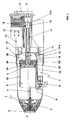
- the device of FIG. 1 comprises a rotary sprayer of coating product 1 provided with a spray bowl 2 driven in rotation by the rotor 3 of an air turbine not shown.
- the projector 1 is supplied with coating product through a conduit 4 having as its source a reservoir 5 mechanically secured to the projector 1.
- a valve 6 for cleaning / filling the reservoir is mounted at the periphery of a housing 7 containing the projector 1 and the reservoir 5.
- the valve 6 is designed to cooperate with a cleaning / filling station (not shown) to which the housing 7 can be moved at the end of the spraying phases.
- the valve 6 is connected to the reservoir 5 by a conduit 8 through which a cleaning product and a coating product circulate according to a predefined sequence.
- a piston 9, movable in translation inside the reservoir 5 is used to push the coating product into the conduit 4 during the spraying phases.
- the housing 7 is mounted on a structural element 10 by means of a quick connector such that, by example, a ring 11 screwed onto an external thread 19 of the structural element 10 and resting on a recess in the housing 7.
- the quick connector could also be a hook system or any other equivalent system.
- the structural element 10 can be the wrist of a multi-axis robot, the arm of a lateral machine or the beam of a roof machine and, in general, any element, mobile or fixed, capable of carrying a projector. coating product.
- An actuating rod 12 is simply supported on the rear face of the stud 9, that is to say the face which is not in contact with the coating product.
- the rod 12 is translated along its axis of symmetry XX ′ thanks to a screw-nut assembly.
- the nut or slide 13, on which the rod 12 is fixed by a key 13a, is immobilized in rotation by a groove and key system not shown. It is moved by the rotation of a screw 14, itself driven by a stepping motor 15 to which it is connected by a set of toothed belts 16.
- An encoder 17, associated with the motor 15, makes it possible to know at all times the position of the motor 15, therefore of the rod 12 and of the piston 9.
- a laying plane 18 traversed in its central part by the actuating rod 12 is mounted at the end of the structural element 10 by means of screws not shown. It comprises orifices 19a, partially shown, into which open air supply conduits for the elements included in the housing 7 and, optionally, electrical connectors not shown, for example intended to allow projection by electrostatic means.
- a centering pin 20 provided on the central part of the rear face of the piston 9 cooperates with a blind hole 21 located at the end of the rod actuation 12 to center the rod on the piston.
- the forces transmitted to the piston 9 by the rod 12 are parallel to the axis XX 'which is also the axis of symmetry of the piston 9.
- the piston does not tend to move perpendicular to this axis, which would risk block, or even damage or damage the cylindrical part of the tank 5.
- a cylindrical jacket 22 made of stainless steel, ceramic or insulating material covers the internal cylindrical wall of the tank 5. This jacket 22 limits the friction of the segments 23 and 23 'and the O-ring 24 carried by the piston 9.
- the jacket 22 is extended by a baffle made of insulating plastic material 25 which penetrates into the recesses 26 formed on the rear face of the piston 9 when the latter is in its position corresponding to the maximum filling of the reservoir 5 shown in FIG. 1.
- This baffle is, inter alia, used during the projection by electrostatic means of coating product; it serves to avoid the ramping of the high voltage of the mass of coating product contained in the tank 5 and brought to high voltage towards the structural element 10 which is grounded.
- Disassembly of the casing 7 also allows the operator to visually check the interior of the reservoir 5 by pushing the piston back into the "empty reservoir” position (on the left in FIG. 1) and checking, for example, that the segments 23 and 23 ′ and the seal 24 are still effective. Indeed, the location of the actuating rod makes it possible to send a light beam into the tank and to inspect it.
- the shirt 22 is not extended by a baffle. It is then possible to extract the piston 9 from the tank 5 by simple pulling to inspect the bottom of the tank.
- the operation is as follows.
- the motor 16 works in accordance with a set point, which turns the screw 14 and moves the slider 13 to the left of FIG. 1.
- the actuating rod 12 fixed on the slider 13 is also moved towards the left and pushes the piston 9 in the same direction, which has the effect of emptying the tank 5 in the direction of the projector 1 in accordance with the instruction.
- the encoder 17 detects the position of the motor 15, which makes it possible to know that of the piston 9. This precise system can be coupled with a digital control.
- the piston 9 rests against the internal face of the reservoir 5 in which the inlet of the duct 4 is formed. As will appear in the description which follows, it is not necessary to hold the piston moved away from the bottom of the tank or to provide spacers on the front face of the piston.
- the actuating rod 12 is moved back a short distance, of the order of 1 mm, which has the effect of moving it away from the piston 9.
- a determined quantity of cleaning product is injected into the conduit 8 through the valve 6.
- This cleaning product opens tangentially on the front face of the piston 9 which it repels since the rod 12 does not hold it in position.
- the volume necessary for the swirling movement of the cleaning product is created by the product itself.
- There is therefore practically no more paint volume lost at the end of each spraying phase which consequently increases the economic performance of the device and reduces the pollution it induces.
- the friction forces of the product on the front face of the piston are higher the smaller the volume into which the product penetrates, which contributes to the cleaning efficiency.
- the rod 12 is brought by the motor 15 to a position close to that which it will have at the end of filling.
- the coating product is then injected into the reservoir 5 and moves the piston until it comes into abutment against the rod 12.
- the only force which must be overcome by the coating product opening into the tank is that of the friction of the piston 5 on the jacket 22.
- the motor 16 and the encoder 17 are not likely to be damaged.
- the product which enters the reservoir must push the rod 12 and this movement is detected by the encoder 17 since it is transmitted by the belts 16 to the motor 15.
- the quantity of product present in the tank 5 can then be adjusted finely by controlling the last millimeters of the piston stroke with the drive system constituted by the motor 15, the toothed belts 16 and the encoder 17.
- FIG. 2 represents a variant of the invention in which elements similar to those of FIG. 1 bear the same references increased by 100.
- This embodiment differs from the previous one in that the actuating rod 112 is fixed on the face rear of the piston 109, for example screwed into a thread 150. In its part furthest from the piston 109, the rod 112 is provided with a groove 151 and rests on two bearings 152 and 153 of a frame 154.
- the frame 154 carries a toothed wheel 155 driven by a disengageable motor 115.
- a sensor 117 for displacement of the rod 112 is also mounted on the frame 154.
- the rod 112 is housed in a sleeve 156 fixed relative to the structural element 110 and integral of the frame 154 thanks to a ring 157. Thanks to the groove, the rotational movements of the toothed wheel in one direction or the other correspond to translation of the rod 112 and of the piston 109 in both directions.
- the motor 115 When it is necessary to dismantle the housing 107, the motor 115 is disengaged and the ring 111 is unscrewed. The housing 107 can then be removed. It drives the rod 112 which is integral with the piston, which is possible since the groove can drive the toothed wheel freely due to the disengagement of the motor 115.
- the disassembly of the housing 107 is thus easy and rapid and has advantages similar to those envisaged with the embodiment of Figure 1.
- the piston 109 is pushed by the rod 112 against the corresponding face of the reservoir 105.
- the motor 115 is disengaged and the cleaning product opening tangentially in the bottom of the tank 105 pushes the piston 109 to a position detected by the sensor 117.
- the motor 115 is re-engaged and blocks the piston in the cleaning position.
- the motor 115 is disengaged until the piston reaches the position corresponding to the desired quantity of coating product according to the characteristics of the object to be coated. It is then re-engaged to lock the piston in position until the start of the projection phase.
- the dosage of the quantity of coating product entering the reservoir is thus quick and precise.
- FIG. 3 represents a second variant of the invention in which elements similar to those of FIG. 1 have the same references increased by 200.
- This embodiment differs from that of FIG. 1 in that the rod 212 is integral with the piston 209, for example integrally formed therewith. At its end furthest from the piston, it is in simple support in a housing 250 located at the end of another rod 251 actuated by a drive system constituted by a stepping motor 215 and by the associated belts 216 A displacement sensor 217 allows the translations of the rod 251 to be controlled.
- the operation is similar to that of the embodiment of FIG. 1, the separation between the two rods 212 and 251 taking place in place of that of the piston 9 with the rod 12.
- the assembly and disassembly are also rapid and the method of the invention can be implemented by causing the rod 251 to be transalted in the X'X direction at the start of the cleaning phase and / or from filling phase of the reservoir 205 to move it away from the rod 212.
- the invention has been presented with a rotary type projector but of course applies to a pneumatic sprayer, electrostatic or not. A combination of the three embodiments shown is further possible.
Abstract
Description
L'invention concerne un dispositif de projection de produit de revêtement du type comprenant un réservoir à piston. Elle concerne en outre un procédé de remplissage du réservoir d'un tel dispositif.The invention relates to a device for spraying coating product of the type comprising a piston reservoir. It further relates to a method of filling the reservoir with such a device.
Dans de nombreuses applications industrielles, on utilise des projecteurs de produit de revêtement embarqués sur des machines qui bougent en regard des objets à revêtir. Il est parfois utile d'associer un réservoir de produit de revêtement à un ou plusieurs projecteurs. Ceci permet par exemple d'appliquer des produits de revêtement électriquement conducteurs, tels que des peintures hydrosolubles, par la voie électrostatique sans recourir à de coûteux et complexes systèmes d'isolation électrique ou à des systèmes de charge électrostatique par effet Corona difficiles à mettre en oeuvre. Des installations de ce type sont connues par les demandes de brevet FR-A-2609252, FR-A-2695327 et FR 9303829 au nom de la demanderesse dont le contenu est inclus, par référence, dans la présente demande.In many industrial applications, coating product projectors on board machines are used which move opposite the objects to be coated. It is sometimes useful to combine a coating product reservoir with one or more projectors. This allows for example to apply electrically conductive coating products, such as water-soluble paints, by the electrostatic way without resorting to expensive and complex electrical insulation systems or to electrostatic charging systems by Corona effect difficult to implement. artwork. Installations of this type are known from patent applications FR-A-2609252, FR-A-2695327 and FR 9303829 in the name of the applicant, the content of which is included, by reference, in the present application.
La précision recherchée pour le débit de produit de revêtement sortant du projecteur dépend essentiellement de la précision de la commande de déplacement du piston à l'intérieur du réservoir. Il est apparu que les systèmes comprenant un piston commandé par une tige d'actionnement sont plus précis que les systèmes à commande pneumatique ou hydraulique, c'est-à-dire pilotés avec un gaz. De plus, les systèmes avec commande pneumatique ou hydraulique comportent nécessairement un régulateur de pression situé entre le réservoir et le projecteur. Ce régulateur sert à piloter la pression ou le débit de produit fourni au projecteur. Il a un volume propre qui correspond à une quantité de produit de revêtement qui ne peut pas être projetée pendant les phases de revêtement: cette quantité doit être déversée dans une purge lors des changements de couleur. Le régulateur doit en outre être nettoyé avec du solvant lors des changements de couleur. Les systèmes avec tige d'actionnement du piston étant plus précis, ils permettent de s'affranchir du régulateur de pression et donc d'économiser du produit et du solvant.The precision sought for the flow rate of coating product leaving the headlight essentially depends on the precision of the movement control of the piston inside the tank. It appeared that the systems comprising a piston controlled by an actuating rod are more precise than the pneumatically or hydraulically controlled systems, that is to say driven with a gas. In addition, systems with pneumatic or hydraulic control necessarily include a pressure regulator located between the tank and the projector. This regulator is used to control the pressure or the flow of product supplied to the projector. It has its own volume which corresponds to a quantity of coating product which cannot be sprayed during the coating phases: this quantity must be poured into a drain when the color changes. The regulator must also be cleaned with solvent when changing colors. The systems with piston actuation rod being more precise, they make it possible to dispense with the pressure regulator and therefore to save product and solvent.
Or, en cours de fonctionnement d'une installation, il peut s'avérer nécessaire de procéder à l'échange standard d'un réservoir ou d'un boîtier contenant un projecteur et un réservoir. Ce changement doit être rapide pour ne pas perturber la production en cours. Il peut aussi être nécessaire d'inspecter l'intérieur d'un réservoir pour détecter des éventuelles fuites de produit. Cette inspection doit aussi être la plus rapide possible.However, during the operation of an installation, it may prove necessary to carry out the standard exchange of a tank or a box containing a projector and a tank. This change must be rapid so as not to disrupt current production. It may also be necessary to inspect the inside of a tank for possible product leaks. This inspection should also be as quick as possible.
Les systèmes connus incluant un piston commandé par une tige ne peuvent pas être démontés facilement. La tâche de l'opérateur est donc longue et délicate, ce qui est incompatible avec une maintenance rapide. Enfin, le coût des moyens d'entraînement et de mesure de déplacement et l'étalonnage dont ils font l'objet ne permettent pas de les changer à chaque opération de maintenance.Known systems including a piston controlled by a rod cannot be dismantled easily. The operator's task is therefore long and delicate, which is incompatible with rapid maintenance. Finally, the cost of the drive and displacement measurement means and the calibration to which they are subject does not allow them to be changed at each maintenance operation.
Dans les systèmes de l'art antérieur, en fin de phase de projection, le piston du réservoir de produit de revêtement ne doit pas être complètement plaqué sur la face correspondante du réservoir afin de permettre le mouvement tourbillonnaire du produit de nettoyage sur sa face avant, c'est-à-dire la face en contact avec le produit de revêtement. On prévoit en général des plots de 1 ou 2 mm qui servent de butée et maintiennent le piston écarté du fond du réservoir. Or, le volume de peinture correspondant est perdu à la fin de chaque phase de projection puisqu'il est déversé dans une purge en étant poussé par le produit de nettoyage. Ceci grève le coût d'exploitation de l'installation. De plus, une partie du produit de nettoyage n'est utilisée que pour évacuer ce reste de peinture et non pour nettoyer effectivement la face avant du piston, ce qui correspond à un second coût supplémentaire.In the systems of the prior art, at the end of the spraying phase, the piston of the coating product tank must not be completely pressed against the corresponding face of the tank in order to allow the swirling movement of the cleaning product on its front face , i.e. the face in contact with the coating product. In general, 1 or 2 mm studs are provided which serve as a stop and keep the piston away from the bottom of the tank. However, the corresponding volume of paint is lost at the end of each spraying phase since it is poured into a drain while being pushed by the cleaning product. This increases the operating cost of the installation. In addition, part of the cleaning product is only used to remove this remaining paint and not to effectively clean the front face of the piston, which corresponds to a second additional cost.
L'invention résout l'ensemble de ces problèmes.The invention solves all of these problems.
Elle concerne un dispositif de projection de produit de revêtement, du type comprenant au moins un projecteur et un réservoir à piston déplacé par une tige d'actionnement, caractérisé en ce que la tige est susceptible d'être désolidarisée mécaniquement du piston ou de ses moyens d'entraînement en translation.It relates to a device for spraying coating product, of the type comprising at least one sprayer and a piston reservoir displaced by an actuating rod, characterized in that the rod is capable of being mechanically detached from the piston or from its means drive in translation.
En particulier, le piston et la tige d'actionnement peuvent être en appui simple l'un contre l'autre. La tige pousse le piston lors des phases de projection, ce qui permet un dosage précis de la quantité de peinture projetée. La tige est solidaire de ses moyens d'entraînement et de mesure de déplacement constitués, par exemple, par un moteur pas à pas et par un codeur, qui sont montés sur l'élément de structure qui supporte l'ensemble constitué par le projecteur et par le réservoir. Le piston est, quant à lui, prisonnier du réservoir. Ainsi, il est possible d'écarter le réservoir et le piston qu'il contient de l'élément de structure et de la tige qui lui est solidaire.In particular, the piston and the actuating rod can be in simple support one against the other. The rod pushes the piston during the spraying phases, which allows precise dosing of the amount of sprayed paint. The rod is integral with its drive and displacement measurement means constituted, for example, by a stepping motor and by an encoder, which are mounted on the structural element which supports the assembly constituted by the projector and by the tank. As for the piston, it is trapped in the tank. Thus, it is possible to separate the reservoir and the piston which it contains from the structural element and from the rod which is integral with it.
Il est aussi possible de prévoir que la tige est solidaire du piston mais qu'elle peut être facilement désengagée de ses moyens d'entraînement et de mesure de déplacement par translation le long de son axe de symétrie: On peut alors écarter aisément de l'élément de structure l'ensemble formé par le réservoir, le piston et la tige.It is also possible to provide that the rod is integral with the piston but that it can be easily disengaged from its drive and displacement measurement means by translation along its axis of symmetry: We can then easily move away from the structural element the assembly formed by the reservoir, the piston and the rod.
Dans les deux cas, le réservoir est solidaire de l'élément de structure par un plan de pose. Par un choix judicieux de la géométrie du réservoir et du plan de pose, il est possible d'accéder à l'intérieur du réservoir rapidement.In both cases, the tank is secured to the structural element by a laying plane. By a judicious choice of the geometry of the tank and the installation plan, it is possible to access the interior of the tank quickly.
L'invention concerne aussi un procédé de remplissage d'un réservoir de produit de revêtement dans un dispositif de projection de produit de revêtement, le réservoir étant du type à piston, caractérisé en ce que, lors des phases de projection, le piston est déplacé par une tige d'actionnement et en ce que, pendant une partie au moins des phases de nettoyage ou de remplissage du réservoir, le piston est déplacé par le produit pénétrant dans le réservoir.The invention also relates to a method for filling a reservoir of coating product in a device for spraying coating product, the reservoir being of the piston type, characterized in that, during the spraying phases, the piston is moved by an actuating rod and in that, during at least part of the tank cleaning or filling phases, the piston is moved by the product entering the tank.
Ce procédé est mis en oeuvre avec un dispositif conforme à l'invention. Pendant les phases de nettoyage ou de remplissage, on peut soit écarter la tige du piston, soit débrayer les moyens d'entraînement en translation de la tige, soit écarter les moyens d'entraînement de la tige. Pendant les phases de nettoyage, c'est le produit de nettoyage qui déplace le piston alors que, pendant les phases de remplissage, c'est le produit de revêtement qui déplace le piston. Grâce à ce procédé, on ne crée pas de volume d'air dans le réservoir avant l'arrivée du produit. On ne risque pas de former des bulles d'air dans le produit présent dans le réservoir. Ce procédé permet aussi de repousser le piston sans que la pression qui le déplace ne soit transmise aux moyens d'actionnement et/ou de mesure de déplacement de la tige. On évite ainsi une trop forte résistance au mouvement du piston, ce qui permet de remplir d'autant plus vite le réservoir et on ne risque pas d'endommager les moyens d'entraînement et de mesure de déplacement en cas de mouvement trop rapide du piston, par exemple à cause d'une surpression dans le conduit d'alimentation en produit de revêtement.This method is implemented with a device according to the invention. During the cleaning or filling phases, it is possible either to move the rod away from the piston, or to disengage the drive means for translating the rod, or to move the drive means away from the rod. During the cleaning phases, it is the cleaning product which moves the piston whereas, during the filling phases, it is the coating product which moves the piston. Thanks to this process, no air volume is created in the tank before the product arrives. There is no risk of forming air bubbles in the product present in the tank. This method also makes it possible to push back the piston without the pressure which displaces it being transmitted to the means for actuating and / or measuring the displacement of the rod. This avoids excessive resistance to movement of the piston, which makes it possible to fill the reservoir all the more quickly and there is no risk of damaging the drive and displacement measurement means in the event of too rapid movement of the piston. , for example due to an overpressure in the coating product supply duct.
L'invention sera mieux comprise et d'autres avantages de celle-ci apparaîtront plus clairement à la lumière de la description qui va suivre de trois modes de réalisation d'un dispositif de projection de produit de revêtement conforme à son principe donnée uniquement à titre d'exemple et faite en référence aux dessins annexés dans lesquels
- la figure 1 est une vue schématique en coupe d'un dispositif selon l'invention,
- la figure 2 est une vue schématique en coupe d'une variante de l'invention et
- la figure 3 est une vue schématique en coupe d'une seconde variante de l'invention.
- FIG. 1 is a schematic sectional view of a device according to the invention,
- FIG. 2 is a schematic sectional view of a variant of the invention and
- Figure 3 is a schematic sectional view of a second variant of the invention.
Le dispositif de la figure 1 comprend un projecteur rotatif de produit de revêtement 1 muni d'un bol de pulvérisation 2 entraîné en rotation par le rotor 3 d'une turbine à air non représentée. Le projecteur 1 est alimenté en produit de revêtement à travers un conduit 4 ayant pour source un réservoir 5 mécaniquement solidaire du projecteur 1. Une vanne 6 de nettoyage/remplissage du réservoir est montée à la périphérie d'un boîtier 7 contenant le projecteur 1 et le réservoir 5. La vanne 6 est prévue pour coopérer avec une station de nettoyage/remplissage non représentée vers laquelle le boîtier 7 peut être déplacé à la fin des phases de projection. La vanne 6 est reliée au réservoir 5 par un conduit 8 où circulent un produit de nettoyage et un produit de revêtement selon une séquence prédéfinie. Un piston 9, mobile en translation à l'intérieur du réservoir 5 est utilisé pour pousser le produit de revêtement dans le conduit 4 au cours des phases de projection.The device of FIG. 1 comprises a rotary sprayer of coating product 1 provided with a
Le boîtier 7 est monté sur un élément de structure 10 au moyen d'un connecteur rapide tel que, par exemple, une bague 11 vissée sur un filetage externe 19 de l'élément de structure 10 et en appui sur un décrochement du boîtier 7. Le connecteur rapide pourrait aussi être un système à crochets ou tout autre système équivalent. L'élément de structure 10 peut être le poignet d'un robot multiaxe, le bras d'une machine latérale ou la poutre d'une machine de toit et, de manière général, tout élément, mobile ou fixe, susceptible de porter un projecteur de produit de revêtement.The
Une tige d'actionnement 12 est en appui simple sur la face arrière du piton 9, c'est-à-dire la face qui n'est pas en contact avec le produit de revêtement. La tige 12 est translatée le long de son axe de symétrie XX' grâce à un ensemble vis-écrou. L'écrou ou coulisseau 13, sur lequel est fixée la tige 12 par une clavette 13a, est immobilisé en rotation par un système à gorge et clavette non représenté. Il est déplacé par la rotation d'une vis 14, elle-même entraînée par un moteur pas à pas 15 auquel elle est reliée par un jeu de courroies crantées 16. Un codeur 17, associé au moteur 15, permet de connaître à chaque instant la position du moteur 15, donc de la tige 12 et du piston 9.An actuating
Un plan de pose 18 traversé dans sa partie centrale par la tige d'actionnement 12 est monté à l'extrémité de l'élément de structure 10 au moyen de vis non représentées. Il comporte des orifices 19a, partiellement représentés, dans lesquels débouchent des conduits d'alimentation en air des éléments inclus dans le boîtier 7 et, éventuellement, des connecteurs électriques non représentés, par exemple destinés à permettre une projection par la voie électrostatique.A laying plane 18 traversed in its central part by the actuating
Un pion de centrage 20 prévu sur la partie centrale de la face arrière du piston 9 coopère avec un trou borgne 21 situé à l'extrémité de la tige d'actionnement 12 pour centrer la tige sur le piston. Ainsi les forces transmises au piston 9 par la tige 12 sont parallèles à l'axe XX' qui est aussi l'axe de symétrie du piston 9. Le piston n'a pas tendance à bouger perpendiculairement à cet axe, ce qui risquerait de le bloquer, voire de l'endommager ou de détériorer la partie cylindrique du réservoir 5. Une chemise cylindrique 22 en acier inox, en céramique ou en matériau isolant recouvre la paroi cylindrique interne du réservoir 5. Cette chemise 22 limite les frottements des segments 23 et 23' et du joint torique 24 portés par le piston 9. Du coté de l'élément de structure 10, la chemise 22 est prolongée par une chicane en matériau plastique isolant 25 qui pénètre dans les creux 26 formé sur la face arrière du piston 9 lorsque celui-ci est dans sa position correspondant au remplissage maximum du réservoir 5 représentée sur la figure 1. Cette chicane est entre autre utilisée lors de la projection par la voie électrostatique de produit de revêtement; elle sert à éviter le rampage de la haute tension de la masse de produit de revêtement contenue dans le réservoir 5 et portée à la haute tension vers l'élément de structure 10 qui est à la masse.A centering pin 20 provided on the central part of the rear face of the
Lorsqu'il est nécessaire de démonter le boîtier 7 pour une opération de maintenance, il suffit de faire tourner la bague 11 pour la désengager du filetage 19 et l'ensemble du boîtier 7 est désolidarisé de l'élément de structure par un mouvement de translation dans la direction XX'. Le pion de centrage 20 est extrait du trou borgne 21 et le piston 9 et la tige d'actionnement 12 sont écartés l'un de l'autre. Même si l'assemblage entre le pion de centrage 20 et le trou borgne 21 était bloqué, l'extraction du pion de centrage aurait bien lieu puisque la chicane 25 de la chemise 22 retient le piston à l'intérieur du réservoir 5. Un autre boîtier 7 peut être immédiatement monté à la place du précédent et la production est interrompue pendant une durée minimale. En pratique, une opération de ce type dure moins d'une minute.When it is necessary to dismantle the
Le démontage du boîtier 7 permet aussi à l'opérateur de contrôler visuellement l'intérieur du réservoir 5 en repoussant le piston dans la position "réservoir vide" (à gauche sur la figure 1) et de vérifier, par exemple, que les segments 23 et 23' et le joint 24 sont toujours efficaces. En effet, l'emplacement de la tige d'actionnement permet d'envoyer un faisceau lumineux dans le réservoir et de l'inspecter.Disassembly of the
Selon une variante de l'invention, la chemise 22 n'est pas prolongée par une chicane. Il est alors possible d'extraire le piston 9 du réservoir 5 par simple traction pour inspecter le fond du réservoir.According to a variant of the invention, the
Par ailleurs, lorsque le boîtier 7 est monté, le fonctionnement est le suivant. Pendant les phases de projection, le moteur 16 travaille conformément à une consigne, ce qui fait tourner la vis 14 et déplace le coulisseau 13 vers la gauche de la figure 1. La tige d'actionnement 12 fixée sur le coulisseau 13 est aussi déplacée vers la gauche et pousse le piston 9 dans la même direction, ce qui a pour effet de vider le réservoir 5 en direction du projecteur 1 conformément à la consigne. Le codeur 17 détecte la position du moteur 15, ce qui permet de connaître celle du piston 9. Ce système précis peut être couplé avec une commande numérique.Furthermore, when the
A la fin de la phase de projection, le piston 9 repose contre la face interne du réservoir 5 dans laquelle est ménagée l'entrée du conduit 4. Comme il va apparaître dans la description qui suit, il n'est pas nécessaire de tenir le piston écarté du fond du réservoir ni de prévoir des plots d'écartement sur la face avant du piston.At the end of the projection phase, the
La tige d'actionnement 12 est reculée d'une faible distance, de l'ordre de 1 mm, ce qui a pour effet de l'écarter du piston 9. Une quantité déterminée de produit de nettoyage est injectée dans le conduit 8 à travers la vanne 6. Ce produit de nettoyage débouche tangentiellement sur la face avant du piston 9 qu'il repousse puisque la tige 12 ne le maintien pas en position. De la sorte, le volume nécessaire au mouvement tourbillonnaire du produit de nettoyage est créé par le produit lui-même. Il n'existe donc pratiquement plus de volume de peinture perdu à la fin de chaque phase de projection, ce qui augmente d'autant les performances économiques du dispositif et diminue la pollution qu'il induit. De plus, les forces de friction du produit sur la face avant du piston sont d'autant plus fortes que le volume dans lequel pénètre le produit est faible, ce qui contribue à l'efficacité du nettoyage.The actuating
Après la phase de nettoyage, la tige 12 est amenée par le moteur 15 dans une position proche de celle qu'elle aura à la fin du remplissage. Le produit de revêtement est alors injecté dans le réservoir 5 et déplace le piston jusqu'à que celui-ci vienne en butée contre la tige 12. Pendant tout ce déplacement, la seule force qui doit être vaincue par le produit de revêtement débouchant dans le réservoir est celle des frottements du piston 5 sur la chemise 22. Comme précédemment, le moteur 16 et le codeur 17 ne risquent pas d'être endommagés. A la fin de la période de remplissage, le produit qui pénètre dans le réservoir doit pousser la tige 12 et ce mouvement est détecté par le codeur 17 puisqu'il est transmis par les courroies 16 au moteur 15. La quantité de produit présente dans le réservoir 5 peut alors être ajustée finement en pilotant les derniers millimètres de la course du piston avec le système d'entraînement constitué par le moteur 15, les courroies crantées 16 et le codeur 17.After the cleaning phase, the
La figure 2 représente une variante de l'invention dans laquelle les éléments similaires à ceux de la figure 1 portent les mêmes références majorées de 100. Ce mode de réalisation diffère du précédent en ce que la tige d'actionnement 112 est fixée sur la face arrière du piston 109, par exemple vissée dans un taraudage 150. Dans sa partie la plus éloignée du piston 109, la tige 112 est pourvue d'une canelure 151 et repose sur deux paliers 152 et 153 d'un bâti 154. Le bâti 154 porte une roue dentée 155 entraînée par un moteur débrayable 115. Un capteur 117 de déplacement de la tige 112 est aussi monté sur le bâti 154. La tige 112 est logée dans un manchon 156 fixe par rapport à l'élément de structure 110 et solidaire du bâti 154 grâce à une bague 157. Grâce à la cannelure, les mouvements de rotation de la roue dentée dans un sens ou dans l'autre correspondent à des translation de la tige 112 et du piston 109 dans les deux sens.FIG. 2 represents a variant of the invention in which elements similar to those of FIG. 1 bear the same references increased by 100. This embodiment differs from the previous one in that the
Lorsqu'il est nécessaire de démonter le boîtier 107, le moteur 115 est débrayé et la bague 111 est dévissée. Le boîtier 107 peut alors être extrait. Il entraîne la tige 112 qui est solidaire du piston, ce qui est possible puisque la cannelure peut entraîner la roue dentée librement du fait du débrayage du moteur 115. Le démontage du boîtier 107 est ainsi aisé et rapide et présente des avantages similaires à ceux envisagés avec le mode de réalisation de la figure 1.When it is necessary to dismantle the
A la fin d'une phase de projection, le piston 109 est poussé par la tige 112 contre la face correspondante du réservoir 105. Comme précédemment, il n'est pas nécessaire de laisser subsister un volume mort de produit de revêtement dans le réservoir. En effet, au début de la phase de nettoyage, le moteur 115 est débrayé et le produit de nettoyage débouchant tangentiellement dans le fond du réservoir 105 pousse le piston 109 jusqu'à une position détectée par le capteur 117. Au signal donné par le capteur 117, le moteur 115 est ré-embrayé et bloque le piston dans la position de nettoyage. De même, pendant la phase de remplissage, le moteur 115 est débrayé jusqu'à que le piston atteigne la position correspondant à la quantité désirée de produit de revêtement en fonction des caractéristiques de l'objet à revêtir. Il est ensuite ré-embrayé pour bloquer le piston en position jusqu'au début de la phase de projection. Le dosage de la quantité de produit de revêtement pénétrant dans le réservoir est ainsi rapide et précis.At the end of a spraying phase, the
La figure 3 représente une seconde variante de l'invention dans laquelle les éléments similaires à ceux de la figure 1 portent les mêmes références majorées de 200. Ce mode de réalisation diffère de celui de la figure 1 en ce que la tige 212 est solidaire du piston 209, par exemple venue de matière avec celui-ci. A son extrémité la plus éloignée du piston, elle est en appui simple dans un logement 250 situé à l'extrémité d'une autre tige 251 actionnée par un système d'entraînement constitué par un moteur pas à pas 215 et par les courroies associées 216. Un capteur de déplacement 217 permet le contôle des translations de la tige 251. Le fonctionnement est similaire à celui du mode de réalisation de la figure 1, la séparation entre les deux tiges 212 et 251 ayant lieu à la place de celle du piston 9 d'avec la tige 12. Le montage et le démontage sont aussi rapides et le procédé de l'invention peut être mis en oeuvre en faisant effectuer à la tige 251 un transaltion dans le sens X'X au début de la phase de nettoyage et/ou de la phase de remplissage du réservoir 205 pour l'écarter de la tige 212.FIG. 3 represents a second variant of the invention in which elements similar to those of FIG. 1 have the same references increased by 200. This embodiment differs from that of FIG. 1 in that the
L'invention a été présentée avec un projecteur de type rotatif mais s'applique bien entendu à un pulvérisateur pneumatique, électrostatique ou non. Une combinaison des trois modes de réalisation représentés est en outre possible.The invention has been presented with a rotary type projector but of course applies to a pneumatic sprayer, electrostatic or not. A combination of the three embodiments shown is further possible.
Claims (10)
Applications Claiming Priority (2)
| Application Number | Priority Date | Filing Date | Title |
|---|---|---|---|
| FR9408930 | 1994-07-13 | ||
| FR9408930A FR2722432B1 (en) | 1994-07-13 | 1994-07-13 | SPRAYING DEVICE COMPRISING A RESERVOIR OF COATING PRODUCT AND METHOD FOR CLEANING AND FILLING SUCH A TANK |
Publications (2)
| Publication Number | Publication Date |
|---|---|
| EP0693319A1 true EP0693319A1 (en) | 1996-01-24 |
| EP0693319B1 EP0693319B1 (en) | 1999-06-09 |
Family
ID=9465536
Family Applications (1)
| Application Number | Title | Priority Date | Filing Date |
|---|---|---|---|
| EP19950410070 Expired - Lifetime EP0693319B1 (en) | 1994-07-13 | 1995-07-11 | Spraying device comprising a container for a coating material and method for cleaning and filling such a container |
Country Status (5)
| Country | Link |
|---|---|
| EP (1) | EP0693319B1 (en) |
| JP (1) | JP3329993B2 (en) |
| DE (1) | DE69510130T2 (en) |
| ES (1) | ES2132568T3 (en) |
| FR (1) | FR2722432B1 (en) |
Cited By (8)
| Publication number | Priority date | Publication date | Assignee | Title |
|---|---|---|---|---|
| DE19610589A1 (en) * | 1996-03-18 | 1997-09-25 | Duerr Gmbh & Co | Process and system for supplying paint to a coating system |
| EP1314483A2 (en) | 2001-11-27 | 2003-05-28 | Dürr Systems GmbH | Method and system for metered delivery of coating material to a coating apparatus |
| WO2004037436A1 (en) * | 2002-10-23 | 2004-05-06 | Fanuc Robotics America, Inc. | Robotic apparatus for painting |
| US7908994B2 (en) | 2005-10-21 | 2011-03-22 | Duerr Systems, Inc. | Automatically steered coating machine also a container for the coating material |
| US8333164B2 (en) | 2006-12-12 | 2012-12-18 | Duerr Systems, Gmbh | Coating apparatus comprising a metering device |
| US8418647B2 (en) | 2005-10-21 | 2013-04-16 | Dürr Systems Inc. | Procedure and piston type metering devices for the metered material supply for a coating device |
| US8689730B2 (en) | 2003-10-23 | 2014-04-08 | Fanuc Robotics America, Inc. | Robotic painting system and method |
| EP2810719B1 (en) | 2005-10-07 | 2018-06-20 | Dürr Systems AG | Supply device for a coating agent and appropriate operating method |
Families Citing this family (4)
| Publication number | Priority date | Publication date | Assignee | Title |
|---|---|---|---|---|
| FR2797787B1 (en) | 1999-08-30 | 2002-02-22 | Sames Sa | COATING PRODUCT PROJECTION DEVICE INCLUDING AT LEAST ONE SPOTLIGHT AND A PISTON TANK |
| JP4709585B2 (en) | 2005-06-09 | 2011-06-22 | トリニティ工業株式会社 | Coating material filling method and apparatus |
| DE102007029195A1 (en) | 2007-06-25 | 2009-02-19 | Dürr Systems GmbH | Coating device for serially coating workpieces with different shades comprises a separate color changer containing color valves to which are connected color lines for the coating material |
| DE102006058562A1 (en) | 2006-12-12 | 2008-08-14 | Dürr Systems GmbH | Coating device for serially coating workpieces with different shades comprises a separate color changer containing color valves to which are connected color lines for the coating material |
Citations (8)
| Publication number | Priority date | Publication date | Assignee | Title |
|---|---|---|---|---|
| US3168120A (en) * | 1961-08-04 | 1965-02-02 | Cypser Frank John | Loading apparatus for caulking gun |
| US4322022A (en) * | 1980-03-19 | 1982-03-30 | Whirlco, Inc. | Quick release for helically-threaded drive unit |
| FR2572662A1 (en) * | 1984-11-05 | 1986-05-09 | Ransburg Sa | METHOD AND APPARATUS FOR AUTOMATIC COATING BY ELECTROSTATIC SPRAY |
| FR2609252A1 (en) | 1987-01-02 | 1988-07-08 | Sames Sa | COATING PROJECTION INSTALLATION, SUCH AS FOR EXAMPLE A PAINT AND IN PARTICULAR A WATER BASED PAINT ELECTROSTATIC PROJECTION INSTALLATION |
| WO1992012798A1 (en) * | 1991-01-28 | 1992-08-06 | The Morgan Crucible Company Plc | Electrostatic spray gun |
| GB2256679A (en) * | 1991-06-11 | 1992-12-16 | Sames Sa | Dispensing liquids |
| EP0563486A1 (en) * | 1992-03-30 | 1993-10-06 | Immuno France S.A.R.L. | Device for applying a pharmaceutical or cosmetic composition |
| FR2695327A1 (en) | 1992-09-09 | 1994-03-11 | Sames Sa | Electrostatic coating device of electrically conductive coating product, provided with an insulated tank adapted to contain such a product. |
Family Cites Families (1)
| Publication number | Priority date | Publication date | Assignee | Title |
|---|---|---|---|---|
| US3066836A (en) * | 1962-02-19 | 1962-12-04 | Pyles Ind Inc | Replaceable dispenser for sealant gun |
-
1994
- 1994-07-13 FR FR9408930A patent/FR2722432B1/en not_active Expired - Lifetime
-
1995
- 1995-07-11 EP EP19950410070 patent/EP0693319B1/en not_active Expired - Lifetime
- 1995-07-11 DE DE1995610130 patent/DE69510130T2/en not_active Expired - Lifetime
- 1995-07-11 ES ES95410070T patent/ES2132568T3/en not_active Expired - Lifetime
- 1995-07-13 JP JP17771095A patent/JP3329993B2/en not_active Expired - Fee Related
Patent Citations (8)
| Publication number | Priority date | Publication date | Assignee | Title |
|---|---|---|---|---|
| US3168120A (en) * | 1961-08-04 | 1965-02-02 | Cypser Frank John | Loading apparatus for caulking gun |
| US4322022A (en) * | 1980-03-19 | 1982-03-30 | Whirlco, Inc. | Quick release for helically-threaded drive unit |
| FR2572662A1 (en) * | 1984-11-05 | 1986-05-09 | Ransburg Sa | METHOD AND APPARATUS FOR AUTOMATIC COATING BY ELECTROSTATIC SPRAY |
| FR2609252A1 (en) | 1987-01-02 | 1988-07-08 | Sames Sa | COATING PROJECTION INSTALLATION, SUCH AS FOR EXAMPLE A PAINT AND IN PARTICULAR A WATER BASED PAINT ELECTROSTATIC PROJECTION INSTALLATION |
| WO1992012798A1 (en) * | 1991-01-28 | 1992-08-06 | The Morgan Crucible Company Plc | Electrostatic spray gun |
| GB2256679A (en) * | 1991-06-11 | 1992-12-16 | Sames Sa | Dispensing liquids |
| EP0563486A1 (en) * | 1992-03-30 | 1993-10-06 | Immuno France S.A.R.L. | Device for applying a pharmaceutical or cosmetic composition |
| FR2695327A1 (en) | 1992-09-09 | 1994-03-11 | Sames Sa | Electrostatic coating device of electrically conductive coating product, provided with an insulated tank adapted to contain such a product. |
Cited By (10)
| Publication number | Priority date | Publication date | Assignee | Title |
|---|---|---|---|---|
| DE19610589A1 (en) * | 1996-03-18 | 1997-09-25 | Duerr Gmbh & Co | Process and system for supplying paint to a coating system |
| EP1314483A2 (en) | 2001-11-27 | 2003-05-28 | Dürr Systems GmbH | Method and system for metered delivery of coating material to a coating apparatus |
| WO2004037436A1 (en) * | 2002-10-23 | 2004-05-06 | Fanuc Robotics America, Inc. | Robotic apparatus for painting |
| US7399363B2 (en) | 2002-10-23 | 2008-07-15 | Fanuc Robotics America, Inc. | Robotic apparatus for painting |
| US7638000B2 (en) | 2002-10-23 | 2009-12-29 | Fanuc Robotics America, Inc. | Robotic apparatus with non-conductive wrist for painting |
| US8689730B2 (en) | 2003-10-23 | 2014-04-08 | Fanuc Robotics America, Inc. | Robotic painting system and method |
| EP2810719B1 (en) | 2005-10-07 | 2018-06-20 | Dürr Systems AG | Supply device for a coating agent and appropriate operating method |
| US7908994B2 (en) | 2005-10-21 | 2011-03-22 | Duerr Systems, Inc. | Automatically steered coating machine also a container for the coating material |
| US8418647B2 (en) | 2005-10-21 | 2013-04-16 | Dürr Systems Inc. | Procedure and piston type metering devices for the metered material supply for a coating device |
| US8333164B2 (en) | 2006-12-12 | 2012-12-18 | Duerr Systems, Gmbh | Coating apparatus comprising a metering device |
Also Published As
| Publication number | Publication date |
|---|---|
| EP0693319B1 (en) | 1999-06-09 |
| FR2722432B1 (en) | 1996-10-25 |
| JP3329993B2 (en) | 2002-09-30 |
| FR2722432A1 (en) | 1996-01-19 |
| JPH0852390A (en) | 1996-02-27 |
| ES2132568T3 (en) | 1999-08-16 |
| DE69510130D1 (en) | 1999-07-15 |
| DE69510130T2 (en) | 2000-01-05 |
Similar Documents
| Publication | Publication Date | Title |
|---|---|---|
| EP0693319A1 (en) | Spraying device comprising a container for a coating material and method for cleaning and filling such a container | |
| EP2821146B1 (en) | Shaking and centrifugation device and method | |
| EP2799148B1 (en) | Laboratory centrifuge including means for locking the translation of a rotor on a drive motor shaft | |
| FR2750780A1 (en) | DOSER COUNTER | |
| FR2943044A1 (en) | HEAD OF DISTRIBUTION OF FLUID PRODUCT | |
| EP0504054A1 (en) | Valve device for establishing a tight connection between two containers and container to be connected to such a device | |
| EP2736639A1 (en) | Leaktight joining device for the aseptic transfer of a biopharmaceutical product between a chamber and a container | |
| EP3996853B1 (en) | Installation for spraying fluid | |
| EP0434535A1 (en) | Electric isolation device forming a duct element and installation having such a device | |
| FR2639260A1 (en) | Stick applicator for a pasty product | |
| WO2015049437A2 (en) | Actuator for a transmission system | |
| EP0592312B1 (en) | Measurer, measure valve and device for measuring successively quantities of liquid | |
| EP1182158A1 (en) | Driving device for winding or unwinding a material web | |
| FR2797787A1 (en) | COATING PRODUCT PROJECTION DEVICE INCLUDING AT LEAST ONE SPOTLIGHT AND A PISTON TANK | |
| FR2720372A1 (en) | Interface device for the transfer of fluid products between two containers. | |
| FR2577899A1 (en) | DISTRIBUTOR CALIBRATOR OF CYLINDRICAL ELEMENTS | |
| EP0348931A1 (en) | Turbomolecular pump | |
| EP1910041B1 (en) | Manipulator and installation comprising the same | |
| FR2931716A1 (en) | APPARATUS FOR THE INSTALLATION OF A CRYING MEMBER | |
| EP0213035B1 (en) | Closing device for a metallic barrel | |
| FR2958834A1 (en) | Apparatus for filling vacuum paper cigarette tubes with finely cut tobacco, has circular passage positioned along longitudinal axis of housing and communicating with parallel plane opposite to cylindrical removable loader | |
| CH641073A5 (en) | Feed mechanism for an automatic lathe | |
| FR2856394A1 (en) | Container corking control device, has corking programs parameterized using microcomputer, and another corking program that controls corking head according to rotation phase of blocking unit | |
| FR2673994A1 (en) | Device for supplying, emptying and collecting the wash water of a meat churn or mixer | |
| FR2775958A1 (en) | Distribution cap for powdered or granular products contained in a flask |
Legal Events
| Date | Code | Title | Description |
|---|---|---|---|
| PUAI | Public reference made under article 153(3) epc to a published international application that has entered the european phase |
Free format text: ORIGINAL CODE: 0009012 |
|
| AK | Designated contracting states |
Kind code of ref document: A1 Designated state(s): BE DE ES GB IT |
|
| 17P | Request for examination filed |
Effective date: 19960403 |
|
| GRAG | Despatch of communication of intention to grant |
Free format text: ORIGINAL CODE: EPIDOS AGRA |
|
| GRAG | Despatch of communication of intention to grant |
Free format text: ORIGINAL CODE: EPIDOS AGRA |
|
| GRAH | Despatch of communication of intention to grant a patent |
Free format text: ORIGINAL CODE: EPIDOS IGRA |
|
| 17Q | First examination report despatched |
Effective date: 19981109 |
|
| GRAH | Despatch of communication of intention to grant a patent |
Free format text: ORIGINAL CODE: EPIDOS IGRA |
|
| GRAA | (expected) grant |
Free format text: ORIGINAL CODE: 0009210 |
|
| AK | Designated contracting states |
Kind code of ref document: B1 Designated state(s): BE DE ES GB IT |
|
| GBT | Gb: translation of ep patent filed (gb section 77(6)(a)/1977) |
Effective date: 19990611 |
|
| REF | Corresponds to: |
Ref document number: 69510130 Country of ref document: DE Date of ref document: 19990715 |
|
| ITF | It: translation for a ep patent filed |
Owner name: ING. ZINI MARANESI & C. S.R.L. |
|
| REG | Reference to a national code |
Ref country code: ES Ref legal event code: FG2A Ref document number: 2132568 Country of ref document: ES Kind code of ref document: T3 |
|
| PLBE | No opposition filed within time limit |
Free format text: ORIGINAL CODE: 0009261 |
|
| STAA | Information on the status of an ep patent application or granted ep patent |
Free format text: STATUS: NO OPPOSITION FILED WITHIN TIME LIMIT |
|
| 26N | No opposition filed | ||
| REG | Reference to a national code |
Ref country code: GB Ref legal event code: IF02 |
|
| BECH | Be: change of holder |
Owner name: *SAMES TECHNOLOGIES SAS Effective date: 20030620 |
|
| BECN | Be: change of holder's name |
Owner name: *SAMES TECHNOLOGIES SAS Effective date: 20030620 |
|
| PGFP | Annual fee paid to national office [announced via postgrant information from national office to epo] |
Ref country code: BE Payment date: 20030812 Year of fee payment: 9 |
|
| REG | Reference to a national code |
Ref country code: GB Ref legal event code: 732E |
|
| PG25 | Lapsed in a contracting state [announced via postgrant information from national office to epo] |
Ref country code: BE Free format text: LAPSE BECAUSE OF NON-PAYMENT OF DUE FEES Effective date: 20040731 |
|
| BERE | Be: lapsed |
Owner name: *SAMES TECHNOLOGIES SAS Effective date: 20040731 |
|
| BERE | Be: lapsed |
Owner name: *SAMES TECHNOLOGIES SAS Effective date: 20040731 |
|
| PGFP | Annual fee paid to national office [announced via postgrant information from national office to epo] |
Ref country code: DE Payment date: 20130709 Year of fee payment: 19 Ref country code: ES Payment date: 20130716 Year of fee payment: 19 |
|
| PGFP | Annual fee paid to national office [announced via postgrant information from national office to epo] |
Ref country code: GB Payment date: 20130719 Year of fee payment: 19 |
|
| PGFP | Annual fee paid to national office [announced via postgrant information from national office to epo] |
Ref country code: IT Payment date: 20130710 Year of fee payment: 19 |
|
| REG | Reference to a national code |
Ref country code: DE Ref legal event code: R119 Ref document number: 69510130 Country of ref document: DE |
|
| GBPC | Gb: european patent ceased through non-payment of renewal fee |
Effective date: 20140711 |
|
| PG25 | Lapsed in a contracting state [announced via postgrant information from national office to epo] |
Ref country code: IT Free format text: LAPSE BECAUSE OF NON-PAYMENT OF DUE FEES Effective date: 20140711 Ref country code: DE Free format text: LAPSE BECAUSE OF NON-PAYMENT OF DUE FEES Effective date: 20150203 |
|
| REG | Reference to a national code |
Ref country code: DE Ref legal event code: R119 Ref document number: 69510130 Country of ref document: DE Effective date: 20150203 |
|
| PG25 | Lapsed in a contracting state [announced via postgrant information from national office to epo] |
Ref country code: GB Free format text: LAPSE BECAUSE OF NON-PAYMENT OF DUE FEES Effective date: 20140711 |
|
| REG | Reference to a national code |
Ref country code: ES Ref legal event code: FD2A Effective date: 20150828 |
|
| PG25 | Lapsed in a contracting state [announced via postgrant information from national office to epo] |
Ref country code: ES Free format text: LAPSE BECAUSE OF NON-PAYMENT OF DUE FEES Effective date: 20140712 |