EP0690630A2 - Digital serial data interface suitable for video and audio data - Google Patents
Digital serial data interface suitable for video and audio data Download PDFInfo
- Publication number
- EP0690630A2 EP0690630A2 EP19950304486 EP95304486A EP0690630A2 EP 0690630 A2 EP0690630 A2 EP 0690630A2 EP 19950304486 EP19950304486 EP 19950304486 EP 95304486 A EP95304486 A EP 95304486A EP 0690630 A2 EP0690630 A2 EP 0690630A2
- Authority
- EP
- European Patent Office
- Prior art keywords
- data
- transmission rate
- media
- signal
- predetermined
- Prior art date
- Legal status (The legal status is an assumption and is not a legal conclusion. Google has not performed a legal analysis and makes no representation as to the accuracy of the status listed.)
- Granted
Links
Images


Classifications
-
- H—ELECTRICITY
- H04—ELECTRIC COMMUNICATION TECHNIQUE
- H04N—PICTORIAL COMMUNICATION, e.g. TELEVISION
- H04N21/00—Selective content distribution, e.g. interactive television or video on demand [VOD]
- H04N21/20—Servers specifically adapted for the distribution of content, e.g. VOD servers; Operations thereof
- H04N21/23—Processing of content or additional data; Elementary server operations; Server middleware
- H04N21/236—Assembling of a multiplex stream, e.g. transport stream, by combining a video stream with other content or additional data, e.g. inserting a URL [Uniform Resource Locator] into a video stream, multiplexing software data into a video stream; Remultiplexing of multiplex streams; Insertion of stuffing bits into the multiplex stream, e.g. to obtain a constant bit-rate; Assembling of a packetised elementary stream
- H04N21/23602—Multiplexing isochronously with the video sync, e.g. according to bit-parallel or bit-serial interface formats, as SDI
-
- H—ELECTRICITY
- H04—ELECTRIC COMMUNICATION TECHNIQUE
- H04L—TRANSMISSION OF DIGITAL INFORMATION, e.g. TELEGRAPHIC COMMUNICATION
- H04L12/00—Data switching networks
- H04L12/02—Details
- H04L12/16—Arrangements for providing special services to substations
- H04L12/18—Arrangements for providing special services to substations for broadcast or conference, e.g. multicast
- H04L12/1863—Arrangements for providing special services to substations for broadcast or conference, e.g. multicast comprising mechanisms for improved reliability, e.g. status reports
-
- H—ELECTRICITY
- H04—ELECTRIC COMMUNICATION TECHNIQUE
- H04L—TRANSMISSION OF DIGITAL INFORMATION, e.g. TELEGRAPHIC COMMUNICATION
- H04L1/00—Arrangements for detecting or preventing errors in the information received
- H04L1/004—Arrangements for detecting or preventing errors in the information received by using forward error control
-
- H—ELECTRICITY
- H04—ELECTRIC COMMUNICATION TECHNIQUE
- H04N—PICTORIAL COMMUNICATION, e.g. TELEVISION
- H04N21/00—Selective content distribution, e.g. interactive television or video on demand [VOD]
- H04N21/20—Servers specifically adapted for the distribution of content, e.g. VOD servers; Operations thereof
- H04N21/23—Processing of content or additional data; Elementary server operations; Server middleware
- H04N21/234—Processing of video elementary streams, e.g. splicing of video streams, manipulating MPEG-4 scene graphs
- H04N21/2343—Processing of video elementary streams, e.g. splicing of video streams, manipulating MPEG-4 scene graphs involving reformatting operations of video signals for distribution or compliance with end-user requests or end-user device requirements
- H04N21/234381—Processing of video elementary streams, e.g. splicing of video streams, manipulating MPEG-4 scene graphs involving reformatting operations of video signals for distribution or compliance with end-user requests or end-user device requirements by altering the temporal resolution, e.g. decreasing the frame rate by frame skipping
-
- H—ELECTRICITY
- H04—ELECTRIC COMMUNICATION TECHNIQUE
- H04N—PICTORIAL COMMUNICATION, e.g. TELEVISION
- H04N21/00—Selective content distribution, e.g. interactive television or video on demand [VOD]
- H04N21/20—Servers specifically adapted for the distribution of content, e.g. VOD servers; Operations thereof
- H04N21/23—Processing of content or additional data; Elementary server operations; Server middleware
- H04N21/236—Assembling of a multiplex stream, e.g. transport stream, by combining a video stream with other content or additional data, e.g. inserting a URL [Uniform Resource Locator] into a video stream, multiplexing software data into a video stream; Remultiplexing of multiplex streams; Insertion of stuffing bits into the multiplex stream, e.g. to obtain a constant bit-rate; Assembling of a packetised elementary stream
- H04N21/2365—Multiplexing of several video streams
-
- H—ELECTRICITY
- H04—ELECTRIC COMMUNICATION TECHNIQUE
- H04N—PICTORIAL COMMUNICATION, e.g. TELEVISION
- H04N21/00—Selective content distribution, e.g. interactive television or video on demand [VOD]
- H04N21/20—Servers specifically adapted for the distribution of content, e.g. VOD servers; Operations thereof
- H04N21/23—Processing of content or additional data; Elementary server operations; Server middleware
- H04N21/236—Assembling of a multiplex stream, e.g. transport stream, by combining a video stream with other content or additional data, e.g. inserting a URL [Uniform Resource Locator] into a video stream, multiplexing software data into a video stream; Remultiplexing of multiplex streams; Insertion of stuffing bits into the multiplex stream, e.g. to obtain a constant bit-rate; Assembling of a packetised elementary stream
- H04N21/2368—Multiplexing of audio and video streams
-
- H—ELECTRICITY
- H04—ELECTRIC COMMUNICATION TECHNIQUE
- H04N—PICTORIAL COMMUNICATION, e.g. TELEVISION
- H04N21/00—Selective content distribution, e.g. interactive television or video on demand [VOD]
- H04N21/20—Servers specifically adapted for the distribution of content, e.g. VOD servers; Operations thereof
- H04N21/23—Processing of content or additional data; Elementary server operations; Server middleware
- H04N21/238—Interfacing the downstream path of the transmission network, e.g. adapting the transmission rate of a video stream to network bandwidth; Processing of multiplex streams
- H04N21/23805—Controlling the feeding rate to the network, e.g. by controlling the video pump
-
- H—ELECTRICITY
- H04—ELECTRIC COMMUNICATION TECHNIQUE
- H04N—PICTORIAL COMMUNICATION, e.g. TELEVISION
- H04N21/00—Selective content distribution, e.g. interactive television or video on demand [VOD]
- H04N21/20—Servers specifically adapted for the distribution of content, e.g. VOD servers; Operations thereof
- H04N21/23—Processing of content or additional data; Elementary server operations; Server middleware
- H04N21/238—Interfacing the downstream path of the transmission network, e.g. adapting the transmission rate of a video stream to network bandwidth; Processing of multiplex streams
- H04N21/2383—Channel coding or modulation of digital bit-stream, e.g. QPSK modulation
-
- H—ELECTRICITY
- H04—ELECTRIC COMMUNICATION TECHNIQUE
- H04N—PICTORIAL COMMUNICATION, e.g. TELEVISION
- H04N21/00—Selective content distribution, e.g. interactive television or video on demand [VOD]
- H04N21/40—Client devices specifically adapted for the reception of or interaction with content, e.g. set-top-box [STB]; Operations thereof
- H04N21/43—Processing of content or additional data, e.g. demultiplexing additional data from a digital video stream; Elementary client operations, e.g. monitoring of home network or synchronising decoder's clock; Client middleware
- H04N21/434—Disassembling of a multiplex stream, e.g. demultiplexing audio and video streams, extraction of additional data from a video stream; Remultiplexing of multiplex streams; Extraction or processing of SI; Disassembling of packetised elementary stream
- H04N21/4341—Demultiplexing of audio and video streams
-
- H—ELECTRICITY
- H04—ELECTRIC COMMUNICATION TECHNIQUE
- H04N—PICTORIAL COMMUNICATION, e.g. TELEVISION
- H04N21/00—Selective content distribution, e.g. interactive television or video on demand [VOD]
- H04N21/40—Client devices specifically adapted for the reception of or interaction with content, e.g. set-top-box [STB]; Operations thereof
- H04N21/43—Processing of content or additional data, e.g. demultiplexing additional data from a digital video stream; Elementary client operations, e.g. monitoring of home network or synchronising decoder's clock; Client middleware
- H04N21/434—Disassembling of a multiplex stream, e.g. demultiplexing audio and video streams, extraction of additional data from a video stream; Remultiplexing of multiplex streams; Extraction or processing of SI; Disassembling of packetised elementary stream
- H04N21/4342—Demultiplexing isochronously with video sync, e.g. according to bit-parallel or bit-serial interface formats, as SDI
-
- H—ELECTRICITY
- H04—ELECTRIC COMMUNICATION TECHNIQUE
- H04N—PICTORIAL COMMUNICATION, e.g. TELEVISION
- H04N21/00—Selective content distribution, e.g. interactive television or video on demand [VOD]
- H04N21/40—Client devices specifically adapted for the reception of or interaction with content, e.g. set-top-box [STB]; Operations thereof
- H04N21/43—Processing of content or additional data, e.g. demultiplexing additional data from a digital video stream; Elementary client operations, e.g. monitoring of home network or synchronising decoder's clock; Client middleware
- H04N21/434—Disassembling of a multiplex stream, e.g. demultiplexing audio and video streams, extraction of additional data from a video stream; Remultiplexing of multiplex streams; Extraction or processing of SI; Disassembling of packetised elementary stream
- H04N21/4347—Demultiplexing of several video streams
-
- H—ELECTRICITY
- H04—ELECTRIC COMMUNICATION TECHNIQUE
- H04N—PICTORIAL COMMUNICATION, e.g. TELEVISION
- H04N21/00—Selective content distribution, e.g. interactive television or video on demand [VOD]
- H04N21/40—Client devices specifically adapted for the reception of or interaction with content, e.g. set-top-box [STB]; Operations thereof
- H04N21/43—Processing of content or additional data, e.g. demultiplexing additional data from a digital video stream; Elementary client operations, e.g. monitoring of home network or synchronising decoder's clock; Client middleware
- H04N21/436—Interfacing a local distribution network, e.g. communicating with another STB or one or more peripheral devices inside the home
- H04N21/4363—Adapting the video or multiplex stream to a specific local network, e.g. a IEEE 1394 or Bluetooth® network
- H04N21/43632—Adapting the video or multiplex stream to a specific local network, e.g. a IEEE 1394 or Bluetooth® network involving a wired protocol, e.g. IEEE 1394
-
- H—ELECTRICITY
- H04—ELECTRIC COMMUNICATION TECHNIQUE
- H04N—PICTORIAL COMMUNICATION, e.g. TELEVISION
- H04N21/00—Selective content distribution, e.g. interactive television or video on demand [VOD]
- H04N21/40—Client devices specifically adapted for the reception of or interaction with content, e.g. set-top-box [STB]; Operations thereof
- H04N21/43—Processing of content or additional data, e.g. demultiplexing additional data from a digital video stream; Elementary client operations, e.g. monitoring of home network or synchronising decoder's clock; Client middleware
- H04N21/438—Interfacing the downstream path of the transmission network originating from a server, e.g. retrieving MPEG packets from an IP network
- H04N21/4382—Demodulation or channel decoding, e.g. QPSK demodulation
-
- H—ELECTRICITY
- H04—ELECTRIC COMMUNICATION TECHNIQUE
- H04N—PICTORIAL COMMUNICATION, e.g. TELEVISION
- H04N21/00—Selective content distribution, e.g. interactive television or video on demand [VOD]
- H04N21/80—Generation or processing of content or additional data by content creator independently of the distribution process; Content per se
- H04N21/85—Assembly of content; Generation of multimedia applications
- H04N21/854—Content authoring
- H04N21/8547—Content authoring involving timestamps for synchronizing content
-
- H—ELECTRICITY
- H04—ELECTRIC COMMUNICATION TECHNIQUE
- H04N—PICTORIAL COMMUNICATION, e.g. TELEVISION
- H04N7/00—Television systems
- H04N7/24—Systems for the transmission of television signals using pulse code modulation
- H04N7/52—Systems for transmission of a pulse code modulated video signal with one or more other pulse code modulated signals, e.g. an audio signal or a synchronizing signal
Definitions
- This invention relates to digital serial data interfaces, for example for transmitting and receiving a digital data signal in a digital data communication system, such as a local area network (LAN), or the like.
- a digital data communication system such as a local area network (LAN), or the like.
- a serial digital interface (SDI) format is proposed by the Society of Motion Picture and Television Engineers (SMPTE) in Proposed SMPTE Standard for Television-10-bit 4:2:2 Component and 4fsc Composite Digital Signals Serial Digital Interface (SMPTE-295M, 1994 Revision-Seventh Draft, Febuary 16, 1994) as a standard for digital audio and video signals.
- SMPTE Society of Motion Picture and Television Engineers
- SMPTE-295M Proposed SMPTE Standard for Television-10-bit 4:2:2 Component and 4fsc Composite Digital Signals Serial Digital Interface
- This SDI standard is basically a standard for signals governed by D-1 or D-2 formats for digital signals.
- the disclosure of Proposed SMPTE standard SMPTE-295M is hereby incorporated herein by reference.
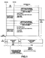
- Fig.1 shows a schematic arrangement of the SDI format which represents the application of D-1 format signals.
- FIG.1 An upper part of Fig.1 shows a frame format of a frame made up of 1716 samples in the horizontal direction and 525 lines in the vertical direction.
- Digital video signals are placed in a first field active video section AVC1 of 1440 horizontal samples and 244 vertical lines and a second field active video section AVC2 of 243 lines.
- the first field active video section AVC1 is a digital video signal of odd fields
- the second field active video section AVC2 is a digital video signal of even fields.
- Ahead of the first field active video section AVC1 and the second video active section AVC2 are respectively inserted 9-line vertical blanking section VBK1, VBK2 and 10-line optional blanking sections OBK1, OBK2.
- Ahead and back of the first field active video section AVC1, second video active section AVC2, vertical blanking sections VBK1, VBK2 and the optional blanking sections OBK1, OBK2 are inserted a 4-sample start synchronization code SAV indicating the start of an active line and a 4-sample end synchronization code EAV indicating the end of the active line.
- SAV and EAV are placed 268 samples of an ancillary data section ANC which are ancillary data for horizontal blanking.
- a mid part of Fig.1 indicates a signal of a frame format shown at the upper part of Fig.1 in a line format having a width of 10 bits.
- parallel/serial conversion and encoding of the transmission channel are carried out as shown at a lower part of Fig.1, and the signals are transmitted as serial signals having a data rate of 270 Mbps.
- the SDI format is not suited as a transmission channel for variegated data, while it is possible to transmit only a limited type of data (information).
- the data sorts capable of being transmitted include one channel of picture signals( or video signals) and 8 channels at most of speech signals (or audio signals) as the base band digital audio signals.
- the SDI format is not suited to transmission and reception of plural channels of the same sort of data or channel multiplication for coping with transmission and reception of plural sorts of data.
- data other than picture signals or speech signals are transmitted over a physically separate channel.
- the SDI format basically takes account only of one-to-one unidirectional data transmission.
- data communication channels such as Ethernet or token ring
- data communication channel inherently has been developed as a data communication channel handling temporally discrete data, such as packet data employed for an electronic computer, while it is not suited as a transmission channel for temporally continuous data, such as picture/video or speech/audio signals, which require maintenance of a temporal relation between the transmitting and receiving sides.
- the data transmission rate of the data communication channel is rather low and is not suited to transmission of picture signals which require wide frequency range, or bandwidth.
- the technological tendency in the near future is to digitize all kinds of the information, inclusive of the picture/video and speech/audio data, and to treat the information simply as a bitstream irrespective of the data type.
- all kinds of data are transmitted as a multiplexed bitstream. If such technical tendency is taken into consideration, the SDI format currently standardized for picture signal transmission is not fully satisfactory, while there lacks at present a particular data format for multiplexing and transmitting various data and control signals among plural communication equipment.
- This invention provides a method of transmitting a digital signal comprising the steps of: assembling a data packet comprised of a first data portion, a start synchronization code and an end synchronization code for bit synchronization for said first data portion, and an auxiliary data portion located between said start synchronization code and said end synchronization code; said auxilliary data portion comprises a type area indicating data type of said first data portion; and transmitting said data packet via a communications network.
- One embodiment of the present invention provides a method for transmitting a digital signal in which a digital signal format of a transmitted digital signal is constituted by a first data portion made up of digital video data, a start synchronization code and an end synchronization code for bit synchronization for the first data portion, and an auxiliary data portion located between the start synchronization code and the end synchronization code and which is made up of plural split areas.
- Each of the split areas of the auxiliary data portion contains at least one of a type area indicating the data type, a byte count area indicating the data volume and a data area which is a second data portion made up of digital audio data.
- a line number area indicating the line number of the data.
- the auxiliary data portion contains an error correction code for detecting and correcting errors in data of the type area and the byte count area.
- the first data portion is made up of digital video data of a plurality of channels and the second data portion is made up of digital audio data of plurality of channels.
- the first data portion could also constitute audio data or other data.
- the second data portion could constitute video or other data.
- the digital signal format contains transmission data and reception data used to identify and characterize the format and nature of the data being transmitted.
- Another embodiment of the present invention provides an apparatus for transmitting a digital signal having a plurality of data outputting media sources, a plurality of delay adjustment units for respectively adjusting the delay of the data from said media sources, a plurality of rate converting units for converting the data transmission rate of the respective data from the rate converting units into a transmission rate of a transmission channel, a plurality of attribute information processing units for appending the attribute information to the respective data from the rate converting units, a multi-media switching unit for optionally selecting data of the respective media sources from the attribute information processing units, a transmission controlling unit for controlling the delay adjustment units, rate converting units, attribute information processing units and the multi-media switching unit, and a multiplexing unit for multiplexing plural data from the multi-media switching unit.
- Another embodiment of the present invention provides a device for receiving a digital signal having a demultiplexing unit for demultiplexing plural multiplexed data into media source based data, a demultiplexed media switching unit for switching plural data from the demultiplexing unit into respective suitable media channels, a plurality of attribute information processing units for processing the plural data switched by the demultiplexed media switching unit based upon the attribute information for these data, a plurality of rate converting units for converting the transmission rate of the respective data from the attribute information processing units into the playback rate for data reproduction, a plurality of delay adjustment units for adjusting the respective data from the plural rate conversion units into optimum delay amounts, and a plurality of media reproducing units for respectively reproducing the data from the delay adjustment units.
- Another embodiment of the present invention provides a digital signal transmission and reception device having the above-mentioned digital signal transmitting device and the above-mentioned digital signal receiving device on the signal transmitting and signal receiving sides, respectively.
- the digital signal such as digital video data or digital video data
- a digital signal format interchangeable with the SDI format of the conventional digital signal transmitting method that is a digital signal format having a first data portion made up of digital video data, a start synchronization code portion, an end synchronization code portion, and an auxiliary data portion.
- Each of the split areas of the auxiliary data portion contains at least one of a type area indicating the data type, a byte count area indicating the data volume, and a data area which is a second data portion made up of digital audio data.
- a line number area indicating the line number of the data, while the first data portion is made up of digital video data of plural channels and the second data portion is made up of digital audio data of plural channels.
- the digital signal format proposed by embodiments of the present invention assures upward compatibility with respect to a device for transmitting and receiving data of the conventional SDI format and hence has affinity, or compatibility, to the existing digital signal transmission system.
- past network resources may be directly exploited, while any newly arising cost may be minimized and the equipment employing the conventional SDI format may be introduced into another sort of network.
- an optional number of line numbers can be set, so that asymmetrical digital signal transmission, such as 1:n transmission, becomes feasible in addition to the conventional 1:1 digital signal transmission.
- auxiliary data portion having error correction code for error detection and correction for the type area data and the byte count area data, digital signals may be transmitted more correctly.
- the first data portion is made up of digital video data of plural channels and the second data portion is made up of digital audio data of plural channels, so that multi-channel transmission of plural media data inclusive of encoded data may be realized on a sole transmission channel.
- the digital signal format contains both the data for transmission and data for reception, so that sole media data may be bi-directionally transmitted by serial digital communication.
- the conventional SDI format employed in video equipment may be extended to a more variegated communication system for general digital data inclusive of base-band audio data and video data, thus enabling more general digital communication. Since communication of plural media data is physically possible by a sole communication medium, system flexibility and hence system maintenance and management such as network modification may be improved significantly.
- the digital signal transmission/reception device of embodiments of the present invention since the arrangement of the digital signal reception device and that of the digital signal transmission device may be combined together, interconnection with a digital data network, such as an external computer, or a digitized public network, such as ISD, as well as with a network between existing video equipment, may be facilitated, thus allowing it to realize reciprocal communication between all sorts of media easily and broadly.
- a digital data network such as an external computer
- a digitized public network such as ISD
- Fig.1 illustrates a schematic arrangement of a conventional SD1 format.
- Fig.2 illustrates a schematic arrangement of a SD1 format according to the method for transmitting a digital signal according to an embodiment of the present invention.
- Fig.3 illustrates a typical arrangement of a line format of the SDI format shown in Fig.1.
- Fig.4a illustrates an illustrative construction of a line number area, type area and a byte count area.
- Fig.4b illustrates an illustrative construction of a line number area, type area and a byte count area.
- Fig.4c illustrates an illustrative construction of a line number area, type area and a byte count area.
- Fig.5a illustrate a construction of a line number area for extension of the number of line numbers.
- Fig.5b illustrate a construction of a line number area for extension of the number of line numbers.
- Fig.5c illustrate a construction of a line number area for extension of the number of line numbers.
- Fig.6a illustrate a schematic construction of a line format according to a first example of application of the SDDI format.
- Fig.6b illustrate a schematic construction of a line format according to a first example of application of the SDDI format.
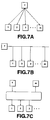
- Fig.7a illustrate a schematic arrangement of a 1:m broadcast communication system when employing a line format of the first example of application of Fig.6.
- Fig.7b illustrate a schematic arrangement of a 1:m broadcast communication system when employing a line format of the first example of application of Fig.6.
- Fig.7c illustrate a schematic arrangement of a 1:m broadcast communication system when employing a line format of the first example of application of Fig.6.
- Fig.8a illustrate a schematic arrangement of a line format of the second example of application of the SDDI format.
- Fig.8b illustrate a schematic arrangement of a line format of the second example of application of the SDDI format.
- Fig.9a illustrate a schematic arrangement of a bidirectional communication system by m transmission and reception equipment when employing the line format of the second example of application of Fig.8.
- Fig.9b illustrate a schematic arrangement of a bidirectional communication system by m transmission and reception equipment when employing the line format of the second example of application of Fig.8.
- Fig.9c illustrate a schematic arrangement of a bidirectional communication system by m transmission and reception equipment when employing the line format of the second example of application of Fig.8.
- Fig.10 illustrates a schematic arrangement of a digital signal transmission and reception apparatus according to an embodiment of the present invention.
- Fig.11 illustrates an arrangement of a digital signal transmission apparatus according to an embodiment of the present invention.
- Fig.12 illustrates an arrangement of a digital signal transmission and reception apparatus according to an embodiment of the present invention.
- Fig. 13 illustrates an embodiment of the present invention.
- Fig. 14 illustrates an embodiment of the present invention.
- Fig. 15 illustrates an embodiment of the present invention.
- Fig.2 illustrates a schematic arrangement of a signal format employing the method for digital signal transmission.
- the signal format is termed a serial digital data interface (SDDI) format.
- SDDI serial digital data interface
- Fig.2 is an application of the D-1 format.
- the SDDI format has a first data section DT1 and a second data section DT2. Ahead of the first data section DT1 and the second data section DT2 are inserted blank data sections BDT1 and BDT2, respectively. Ahead and back of the data sections DT1 and DT2 and the blank data sections BDT1 and BDT2 are put 4-sample start synchronization code SAV and 4-sample end synchronization code EAV, respectively. Between the start synchronization code SAV and the end synchronization code EAV is put an ancillary data section ANC, which is auxiliary data.
- the present SDDI format represents extension of the SDI in some respects.
- a frame format shown at an upper part of Fig.2 that is the blank data sections BDT1 and BDT2 of the format in the vertical direction, may be freely changed as to the positions and the numbers of lines thereof by setting of the data type and the line numbers as later explained.
- the blank data sections BDT1 and BDT2 may be set in the same manner as for the conventional SDI format. Consequently, with a system configuration in which signal switching may be made at a vertical blanking period by an existing lauter or switcher, SDDI format data may be employed in a form in which it is precompleted in units in the vertical blanking period. Also, depending on data setting, effective data may be inserted in the entire frame area to provide data sections DT1, DT2.
- the SDDI format allows for flexible system construction.
- the line format shown at a mid part of Fig.2, that is the horizontal format, is made up of a 4-sample end synchronization code EAV, 268-sample ancillary data section ANC, a 4-sample start synchronization code SAV and a 1440-sample payload section PAD.
- EAV 4-sample end synchronization code
- ANC 2-68-sample ancillary data section
- SAV 4-sample start synchronization code SAV
- a 1440-sample payload section PAD 1440-sample payload section
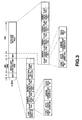
- Fig.3 shows an illustrative constitution of the SDDI format.
- a line number area LN indicating the number to which belongs the line data, as shown at an upper part of Fig.3.
- the vertical blanking domain of a particular line number can be regenerated, as in the case of the conventional SDI format.
- Within the ancillary data section ANC can be put audio data and control data of plural channels, such as audio data areas AD1 or AD2 or control data area CD1, in a mixed state.
- data of one channel can occupy data areas of a variable length based upon respective transmission rates of plural sorts of data.
- the audio data area AD or the control area data CD are combined with flags FG to constitute one-channel data.
- Such one-channel data may be constituted by a flag FG1, an audio data area AD1, a flag FG2, an audio data area AD2, a flag FG3, a control data area CD1, a flag FG4, ;as shown for example at Fig.3.
- One data channel is made up of a type area TP, a byte count area BC, an error correction code ECC and a data area DT, as shown at a mid part of Fig.3.
- the type area TP denotes the contents of data of the data area DT
- the byte count area BC denotes the length of data of the data area DT.
- the error correction code ECC includes a check sum or a cyclic redundancy code (CRC) of the type area TP and the byte count area BC.
- CRC cyclic redundancy code
- the payload section PAD can be put video data of plural channels in a mixed state.
- the video data of the respective channels is made up of flags FG and video areas VD.
- the video data is constituted by a flag FG1, a video data area VD1, a flag FG2, a video data area VD2, a flag FG3, a video data area VD3, a flag FG4, a video data area VD4, flag FG5, ;as shown at a lower part of Fig.3.
- One data channel is made up of a type area TP, a byte count area BC, an error correction code ECC and a data area DT, similarly to the constitution of the data channel in the ancillary data section ANC, as shown at a lower part of Fig.3.
- the line number area LN is made up of 10 bits and indicate the line number by 7 bits, that is bit 0 (LN0) up to bit 6 (LN6).
- Bit 7 or LCY is a bit for extension of the line number area and indicates whether or not the line number area LN has been extended.
- Bit 8 and bit 9 indicate an even number parity of the values from bit 0 to bit 7 and an inversion of the bit 8, respectively.
- the number of the line number areas LN may be increased by setting the bit 7, if necessary, as described above.
- the illustrative construction of the line number area at the time of extension of the number of line numbers is shown in Fig.5A, Fig. 5B & Fig. 5C. If the bit 7 of the line number area LN is 0, as shown in Fig. 5A, the line number area LN is not extended and the line number is indicated solely by the line number area LN. However, if the bit 7 of the first line number area LN1 is 1, as shown at a mid part of Fig.5B, the next 1-word area, made up of 10 bits, is also an area indicating the line number, that is a line number area LN2.
- the line number area LN2 since bit 7 of the line number area LN2 is 0, the region up to the bit 7 becomes the line number area LN.
- the line number area may be extended by two words, as shown in Fig.5c.
- the line number is denoted using LN0 to LN20 by bits 0 to 6 of the line areas LN1 LN2 and LN3.
- An optional number of line numbers may be set by extending the line number area LN in this manner.
- the type area shown in Fig.4b and the byte count area shown in Fig.4c are defined as header data for data.
- the type area TP denotes the contents of data by the values of from T0 of bit 0 to T6 of bit 6.
- Data types are defined depending on the data sorts, such as type '00' for audio data of the MPEG system and for video data of the MPEG system, respectively.
- data types of invalid data such as blank data, it becomes possible to set a line corresponding to the vertical blanking domain, while it also becomes possible to cope with a system of switching the signals on the field basis, such as an existing lauter or a switcher.
- the byte count area BC denotes the length of the next following data area DT by the values of BC0 of bit 0 to BC6 of bit 6.
- both the type area TP and the byte count area BC can be extended depending on the value of the extension bit of bit 7 thus enabling flexible area setting.
- the bit 8 of the type area TP and bit 8 of the byte count area BC are even-number parities of the values of bit 0 to bit 7, while bit 9 of the type area TP and bit 9 of the byte count area BC are inverted values of the bits 8.
- the resulting format is the conventional D-1 format itself, thus assuring complete interchangeability between the SDDI format signals and the SD1 format signals.
- FIG.6A An example of a first application of the method for digital signal transmission is shown in Fig.6A and Fig.6B.
- each of the ancillary data section and the payload section in the SDDI format is divided into data having n sub-areas, as shown in Fig.6a.
- the entire area excluding the start synchronization code SAV and the end synchronization code EAV is divided into data having n sub-areas, as shown in Fig.6b. If, when the area is divided into n sub-areas in the SDDI format, as with the present first example of application, each of data communication equipment having a 1:m connection employs each 1/n sub-area, it becomes possible to achieve n-channel broadcast type data communication between a data transmission equipment and m data reception equipment.
- the interconnection between the data transmission equipment T and the m data reception equipment may be of a star shape as shown in Fig.7A, a bus type as shown in Fig.7b or of a ring type as shown in Fig.7c. It is also possible for the m data reception equipment to receive data of a desired one of n sub-areas or to perform communication service of receiving data of synchronous reception of data of a specified sub-area.
- FIG.8A A second example of application of the method for digital signal transmission is shown in Fig.8A and Fig. 8B
- each of the ancillary data section and the payload section in the SDDI format is divided into data having n sub-areas, with the ancillary section being used as a channel for data transmission and the payload section being used as a channel for data reception, as shown in Fig.8a.
- each area is time-multiplexed so as to be used for transmission and reception each by 1/n of the channel time, as shown in Fig.8b.
- the area in the SDDI format is divided into n sub-areas dedicated to transmission and reception, it becomes possible to achieve bidirectional serial digital data communication between desired two of interconnected m data transmission/reception equipment.
- the interconnection between the data transmission equipment T and the m data reception equipment may be of a star shape as shown in Fig.9a, a bus type as shown in Fig.9b or of a ring type as shown in Fig.9c.
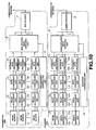
- FIG.10 A schematic arrangement of a digital signal transmission and reception apparatus, employing the above-described method for digital signal transmission, is shown in Fig.10.
- the basic data flow on the transmission side 100 of the digital signal transmission and reception device is symmetrical with respect to its reception side. That is, the transmission side 100(transmitter) serially transmits signals multiplexed from data from a desired media source, while the reception side receives and reproduces the serially transmitted signals from the media source.
- the transmission side 100 incorporates a plurality of input channels for receiving and processing data from a pluraltiy of media sources (media source data).
- the transmitting, or transmission, side 100 receives the media source data from media sources 11 to 1 n and transmits it to delay adjustment units 21 to 2 n , respectively.
- the delay adjustment units 21 to 2 n delay the output of the different media data by a predetermined amount as part of the process of getting all data to flow at a common data transmission rate.
- Output data of the delay adjustment units 21 to 2 n are transmitted to rate conversion units (data transmission rate converters) respectively.
- the rate conversion units 31 to 3 n convert the data transfer rates of the input data into the rate of transmission on the communication transmission channel(network).
- the data transmission rate is converted to a common data transmission rate.
- the media data, rate-converted by the rate conversion units 31 to 3 n are subsequently transmitted to attribute information processing units (attribute data processors) 41 to 4 n , respectively.
- the attribute information processing units 41 to 4 n append subsidiary data, or attribute data, to the respective media data.
- the appended attribute data may be the above-mentioned type area data or the byte count data in the SDDI format as previously explained.
- the data having the attribute data appended thereto in the attribute data processing units 41 to 4 n are transmitted to a multi-media switching unit 5.
- the multi-media switching unit 5 optionally or alternately selects plural data from the media data output from the attribute processors and transmits the selected data to a multiplexing unit (multiplexor) 7.
- a transmission control unit 6 transmits the control information to the delay adjustment units 21 to 2 n , rate conversion units 31 to 3 n , attribute information processing units 41 to 4 n and to a multi-media switching unit 5, and causes processing to be performed in the delay adjustment units 21 to 2 n , rate conversion units 31 to 3 n , attribute information processing units 41 to 4 n and in multi-media switching unit 5 based upon the control information.
- the multiplexing unit 7 multiplexes transmitted data from the attribute data processor into a serial signal which then is transmitted to a communication transmission channel, such as a communication network/LAN.
- the receiving, or reception, side 200(receiver) receives the transmitted multiplexed data and transmits the received data to a separating unit (De-multiplexor) 8.
- the separating unit 8 demultiplexes the multiplexed serial data of plural media into the media data.
- the plural media-based data are transmitted to a demultiplexed media switching unit 9.
- the demultiplexed media switching unit 9 switches the transmitted media-based data to the appropriate media channel to transmit the data to attribute information processing unit (attribute data decoder) associated with the suitable media channels in attribute information processing units 101 to 10 n .
- attribute information processing unit attribute information processing unit
- the attribute information processing units 101 to 10 n carry out required processing and conversion and subsequently delete the attribute information from the data.
- Part of the attribute information is routed to a reception controlling unit 14 so as to be used for control in the reception controlling unit 14.
- Output data of the attribute information processing units 101 to 10 n are routed to rate conversion units (data transmission rate converters) 111 to 11 n . Since the data rate is the rate of transmission of the communication transmission channel, the rate conversion units 111 to 11 n convert the data rate to a rate matched to data reproduction of the respective media data.
- the rate-converted data are routed to delay adjustment units 121 to 12 n .
- the delay adjustment units 121 to 12 n perform delay processing most suited to the media on the transmitted data. These data are routed to and reproduced in the media reproducing units 131 to 13 n .
- the reception control unit 14 routes the control information to the demultiplexing media switching unit 9, attribute information processing units 101 to 10 n , rate conversion units 111 to 11 n and to the delay adjustment units 121 to 12 n . Processing by the demultiplexing media switching unit 9, attribute information processing units 101 to 10 n , rate conversion units 111 to 11 n and to the delay adjustment units 121 to 12 n is carried out based upon the transmitted control information.
- a digital signal transmission and reception device for transmitting the encoded digital video signals, digital audio signals and non-compacted digital audio data is hereinafter explained.
- FIG.11 An illustrative arrangement of a digital signal transmission device within the digital signal transmission and reception device is shown in Fig.11.
- an audio encoding device 16 and an audio signal input unit 17 of Fig.11 there are supplied encoded media source data such as video data, encoded audio data and non-compacted audio data,respectively, sampled by sampling clock signals from a picture clock generator 18 generating sampling clock signals for data of the respective media, an audio clock oscillator 19 and sampling clock signals from an audio sampling oscillator 20.
- the sampling clocks generated by the audio clock generator 19 and the audio sampling oscillator 20 are derived from the sampling clock signals of the video data generated by the picture clock generator 18.
- the audio sampling oscillator 20 generates sampling clock signals based upon clock signals from the audio clock generator 19.
- the encoded video data, encoded audio data and non-compacted audio data from the respective media are fed to delay processing FIFO memories 22, 23 and 24 adapted for adjusting the media-based delay caused by processing, such as encoding.
- the delay processing FIFO memories 22 to 24 are fed with sampling clock signals from the picture clock oscillator 18, audio clock oscillator 19 and the audio sampling oscillator 20, respectively.
- the encoded video data, encoded audio data and non-compacted audio data from the respective media are delayed to the extent required for the respective data, under control by a transmission control unit 21, so as to be written in the delay processing FIFO memories 22 to 24, based upon the input sampling clock signals, respectively.
- the respective media data are matched in time phase by the delay processing.
- the encoded video data in the delay processing FIFO memory 22 and the encoded audio data in the delay processing FIFO memory 23 are subsequently read out based upon the sampling clock signals from the picture clock oscillator 18 and the audio clock generator 19 so as to be written in rate conversion FIFO memories 25 and 26, respectively.
- the data written in the rate conversion FIFO memories 25 and 26 are read out based upon transmission clock signals, that is clock signals generated by a transmission clock generator 27, so as to be sampled at the transmission rate and processed with rate conversion.
- the rate-converted data from the rate converting FIFO memories 25 and 26 are routed to header data appending units 28 and 29, respectively.
- the header data appending units 28 and 29 append header data required for the respective data.
- the non-compacted audio data in the delay processing FIFO memory 24 are routed to a rate converting and audio data flag appending unit 30 which is also fed with clock signals from the transmission clock generator 27.
- the data rate conversion and data appendage such as appendage of audio data flags, are collectively carried out at the rate converting and audio data flag appending unit 30.
- a multi-media switching unit 31 selects one of the output encoded audio data from the header data appending unit 29 and the non-compacted audio data outputted from the rate converting and audio data flag appending unit 30.
- the audio data as selected by the multi-media switching unit 31 and the output encoded video data from the header data appending unit 28 are multiplexed in a multiplexing unit 32, using clock signals from the transmission clock generator 27.
- the resulting multiplexed serial signals are transmitted to a transmission encoding and outputting unit 33.
- the transmission encoding and outputting unit 33 performs appropriate transmission channel encoding on the transmitted multiplexed data and outputs the processed data to a communication network.
- the transmitted data is received and reproduced by a digital signal reception device shown in Fig.12.
- the transmitted data is first received by a transmission decoding and reception unit 34 of Fig.12 and transmission channel decoded so as to be then supplied to a demultiplexing unit 35.
- the demultiplexing unit 35 demultiplexes the transmitted data to respective media-based data.
- the transmission clock signal data are routed to a reception clock reproducing unit 36 where transmission clock signals are reproduced. From the reproduced transmission clock signals are derived the above-mentioned reproducing clock signals generated by a picture clock generator 40, a sound clock oscillator 41 and a sound sampling oscillator 42 inputting the reproducing clock signals to a picture decoding device 37, an audio decoding device 38, an audio decoding device 38 and an acoustic signal outputting unit 39.
- the audio data is transmitted to a demultiplexed media switching unit 43.
- the demultiplexed media switching unit 43 changes over the transmitted audio data by the encoded audio data or the non-compacted audio data so that the encoded audio data and the non-compacted audio data are transmitted to a header data processing unit 44 and to a rate converting and audio data flag processing unit 45, respectively.
- the header data processing unit 44 performs data processing using header data of the transmitted encoded audio data.
- the header data is simultaneously transmitted to a reception control unit 49.
- the processed data is written in a rate converting FIFO memory 46, based on the transmission clock signals from the reception clock reproducing unit 36, and is subsequently read out based upon the reproducing clock signals from the audio clock oscillator 41, under control by the reception controlling unit 49, in order to perform rate conversion on the sampling clock signals of the encoded audio data.
- the rate converting and audio data flag processing unit 45 collectively processes the transmitted non-compacted audio data with data rate conversion based upon the reproducing clock signals from the sound sampling oscillator 42 and with data processing employing the audio data flag.
- the rate-converted data from the rate converting FIFO memory 46 and the processed data from rate converting and audio data flag processing unit 45 are written in delay adjustment FIFO memories 47 and 48, based upon the reproducing clock signals from the audio clock oscillator 41.
- the delay adjustment FIFO memories 47 and 48 are controlled by the reception controlling unit 49 for delay adjustment among the respective media taking into account the delay caused in the respective media due to decoding.
- the data adjusted for delay is read out from the delay adjustment FIFO memories 47 and 48 based upon the reproducing clock signals from the sound clock oscillator 41 so as to be transmitted to the audio decoding device 38 and the audio signal outputting unit 39.
- the transmitted encoded audio data is decoded by the audio decoding device 38 to reproduce digital audio data.
- Digital audio data is also outputted from the audio signal output 39.
- the video data demultiplexed by the demultiplexing unit 35 is transmitted to a header data processing unit 50.
- the header data processing unit 50 performs data processing using header data of the transmitted encoded video data.
- the header data information is also supplied to the reception controlling unit 49.
- the processed data is written in a rate converting FIFO memory 51, based upon transmission clock signals from the reception clock reproducing unit 36, and is subsequently read out based upon the reproducing clock signals from the picture clock oscillator 40 under control by the reception controlling unit 49, for rate converting the sampling clock signals of the encoded video data.
- the rate converted data from the rate converting FIFO memory 51 is written in a delay adjustment FIFO memory 52 based on the playback clock signals from the picture clock oscillator 40.
- the delay adjustment FIFO memory 52 is controlled by the reception controller 49 as to delay adjustment among the respective media taking into account the delay introduced by e.g., decoding for the respective media.
- the delay- adjusted data is read from the delay adjustment FIFO memory 52, based upon the reproducing clock signals from the picture clock oscillator 40, so as to be supplied to the picture decoding device 37.
- the picture decoding device 37 decodes the transmitted encoded video data for reproducing digital video data.
- FIG. 13 Another embodiment of the present invention is shown in Fig. 13 .
- This embodiment incorporates a sensor 800 for reading data, such as video data 810, audio data 820, graphic data or text data, from an optical disc recording medium 840 such as, for example, a digital video disc, compact disc, mini disc or the like.
- a transmitter 830 such as that described n Fig.10, is included to accomodate each type of data read from the optical disc, and to process the data read from the optical disc to append header or attribute data and to convert the data transmission rate of each type of input data to a common data transmission rate.
- One example of this embodiment includes a video camera or imager and recorder device for recording video or audio data onto the optical recording medium.
- FIG. 14 Another embodiment is shown in Fig. 14 and includes a magnetic reproducing head 900 for reading data recorded on a magnetic recording medium 940 such as, for example, a magnetic tape or disc.
- the signal read from the magnetic recording medium (video data signal 910 and audio data signal 920) is then passed to a transmitter 930 such as that described in Fig 10, where it is then processed to add header or attribute data and to convert the data tranmission rate to a common, predetermined data transmission rate.
- a video camera or imager and recorder device for recording video or audio data onto the magnetic recording medium.
- FIG. 15 A further embodiment of the present invention is shown in Fig. 15.
- Data such as video, audio or text data, from a plurality of various sources are input and received by the encoder (ENC) 1500, which transforms input data from one predetermined format into an output signal of another predetermined format at predetermined data transmission rate.
- Encoder 1500 performs the function of the transmission side 100 previously described herein.
- the output of Encoder 1500 is then provided to an input router 1510 which is controlled by Server Management System controller(SMS) 1520.
- SMS Server Management System controller
- the output from input router 1510 is directed to Server Data Controller (SDC) 1530 which directs the input data from Input router 1510 to a recorder/player MOD 1540 for selectively recording the input data onto a recording medium 1550, such as an Magneto Optical disk.
- SDC Server Data Controller
- Recorder/Player 1540 also performs the function of reading data recorded on a recording medium 1550 and outputting same to an output router 1560.
- Output router 1560 then outputs the data read from recording medium 1550 to a decoder section (DEC) 1570 which performs the functions of the receiving side 200 previously described herein.
- DEC decoder section
- Output data from decoder 1570 can then be routed to any number of devices, including reproduction devices for the various data formats, or editing equipment for selectively compiling data into a desired sequence or form.
- embodiments of the invention provide a method and apparatus for transmitting and receiving a digital signal, whereby plural sorts, or types, of picture/video and speech/audio signals and the like may be transmitted as one bitstream.
Abstract
Description
- This invention relates to digital serial data interfaces, for example for transmitting and receiving a digital data signal in a digital data communication system, such as a local area network (LAN), or the like.
- Among the apparatus for handling and receiving speech signals or audio signals, there is video equipment, such as a television, or audio equipment, such as a radio, CD player, MD player or a video tape recorder (VTR). As a method for communication of signals employed in such apparatus, such as a video tape recorder (VTR), with other equipment, a serial digital interface (SDI) format is proposed by the Society of Motion Picture and Television Engineers (SMPTE) in Proposed SMPTE Standard for Television-10-bit 4:2:2 Component and 4fsc Composite Digital Signals Serial Digital Interface (SMPTE-295M, 1994 Revision-Seventh Draft, Febuary 16, 1994) as a standard for digital audio and video signals. This SDI standard is basically a standard for signals governed by D-1 or D-2 formats for digital signals. The disclosure of Proposed SMPTE standard SMPTE-295M is hereby incorporated herein by reference.
- Fig.1 shows a schematic arrangement of the SDI format which represents the application of D-1 format signals.
- An upper part of Fig.1 shows a frame format of a frame made up of 1716 samples in the horizontal direction and 525 lines in the vertical direction. Digital video signals are placed in a first field active video section AVC₁ of 1440 horizontal samples and 244 vertical lines and a second field active video section AVC₂ of 243 lines. Specifically, the first field active video section AVC₁ is a digital video signal of odd fields and the second field active video section AVC₂ is a digital video signal of even fields. Ahead of the first field active video section AVC₁ and the second video active section AVC₂ are respectively inserted 9-line vertical blanking section VBK₁, VBK₂ and 10-line optional blanking sections OBK₁, OBK₂. Ahead and back of the first field active video section AVC₁, second video active section AVC₂, vertical blanking sections VBK₁, VBK₂ and the optional blanking sections OBK₁, OBK₂ are inserted a 4-sample start synchronization code SAV indicating the start of an active line and a 4-sample end synchronization code EAV indicating the end of the active line. Between the start synchronization code SAV and the end synchronization code EAV are placed 268 samples of an ancillary data section ANC which are ancillary data for horizontal blanking. A mid part of Fig.1 indicates a signal of a frame format shown at the upper part of Fig.1 in a line format having a width of 10 bits. For transmitting signals of the SDI format, parallel/serial conversion and encoding of the transmission channel are carried out as shown at a lower part of Fig.1, and the signals are transmitted as serial signals having a data rate of 270 Mbps.
- Although data transmission by the SDI format is achieved at a high speed, the SDI format is not suited as a transmission channel for variegated data, while it is possible to transmit only a limited type of data (information). Specifically, the data sorts capable of being transmitted include one channel of picture signals( or video signals) and 8 channels at most of speech signals (or audio signals) as the base band digital audio signals. Thus the SDI format is not suited to transmission and reception of plural channels of the same sort of data or channel multiplication for coping with transmission and reception of plural sorts of data. On the other hand, data other than picture signals or speech signals are transmitted over a physically separate channel. In addition, the SDI format basically takes account only of one-to-one unidirectional data transmission.
- In general, when simultaneously transmitting plural sorts of data, the method of providing a data transmissior. channel for each data sort is simple and easy, it being unnecessary to carry out data processing for transmitting excessive data. However, this presents a problem in efficiency and economic profitability in connection with cost involved in the entire data transmission system, cost involved in the data transmission channel, or labor in maintenance or extendibility of the data transmission system.
- In local networks employed in data communication (LAN), especially in information processing equipment, data communication channels, such as Ethernet or token ring, have become popular in use. However, such data communication channel inherently has been developed as a data communication channel handling temporally discrete data, such as packet data employed for an electronic computer, while it is not suited as a transmission channel for temporally continuous data, such as picture/video or speech/audio signals, which require maintenance of a temporal relation between the transmitting and receiving sides. On the other hand, the data transmission rate of the data communication channel is rather low and is not suited to transmission of picture signals which require wide frequency range, or bandwidth.
- The technological tendency in the near future is to digitize all kinds of the information, inclusive of the picture/video and speech/audio data, and to treat the information simply as a bitstream irrespective of the data type. Above all, in the future digital integrated network, exemplified by the AM technique, all kinds of data are transmitted as a multiplexed bitstream. If such technical tendency is taken into consideration, the SDI format currently standardized for picture signal transmission is not fully satisfactory, while there lacks at present a particular data format for multiplexing and transmitting various data and control signals among plural communication equipment.
- This invention provides a method of transmitting a digital signal comprising the steps of:
assembling a data packet comprised of a first data portion, a start synchronization code and an end synchronization code for bit synchronization for said first data portion, and an auxiliary data portion located between said start synchronization code and said end synchronization code;
said auxilliary data portion comprises a type area indicating data type of said first data portion; and
transmitting said data packet via a communications network. - Further respective aspects of the invention are defined in the appended claims.
- One embodiment of the present invention provides a method for transmitting a digital signal in which a digital signal format of a transmitted digital signal is constituted by a first data portion made up of digital video data, a start synchronization code and an end synchronization code for bit synchronization for the first data portion, and an auxiliary data portion located between the start synchronization code and the end synchronization code and which is made up of plural split areas. Each of the split areas of the auxiliary data portion contains at least one of a type area indicating the data type, a byte count area indicating the data volume and a data area which is a second data portion made up of digital audio data.
- At the leading end of the auxiliary data portion, there is provided a line number area indicating the line number of the data.
- The auxiliary data portion contains an error correction code for detecting and correcting errors in data of the type area and the byte count area.
- The first data portion is made up of digital video data of a plurality of channels and the second data portion is made up of digital audio data of plurality of channels. Of course, the first data portion could also constitute audio data or other data. Likewise, the second data portion could constitute video or other data. The digital signal format contains transmission data and reception data used to identify and characterize the format and nature of the data being transmitted.
- Another embodiment of the present invention provides an apparatus for transmitting a digital signal having a plurality of data outputting media sources, a plurality of delay adjustment units for respectively adjusting the delay of the data from said media sources, a plurality of rate converting units for converting the data transmission rate of the respective data from the rate converting units into a transmission rate of a transmission channel, a plurality of attribute information processing units for appending the attribute information to the respective data from the rate converting units, a multi-media switching unit for optionally selecting data of the respective media sources from the attribute information processing units, a transmission controlling unit for controlling the delay adjustment units, rate converting units, attribute information processing units and the multi-media switching unit, and a multiplexing unit for multiplexing plural data from the multi-media switching unit.
- Another embodiment of the present invention provides a device for receiving a digital signal having a demultiplexing unit for demultiplexing plural multiplexed data into media source based data, a demultiplexed media switching unit for switching plural data from the demultiplexing unit into respective suitable media channels, a plurality of attribute information processing units for processing the plural data switched by the demultiplexed media switching unit based upon the attribute information for these data, a plurality of rate converting units for converting the transmission rate of the respective data from the attribute information processing units into the playback rate for data reproduction, a plurality of delay adjustment units for adjusting the respective data from the plural rate conversion units into optimum delay amounts, and a plurality of media reproducing units for respectively reproducing the data from the delay adjustment units.
- Another embodiment of the present invention provides a digital signal transmission and reception device having the above-mentioned digital signal transmitting device and the above-mentioned digital signal receiving device on the signal transmitting and signal receiving sides, respectively.
- With the method for transmitting the digital signal according to embodiments of the present invention, the digital signal, such as digital video data or digital video data, is transmitted in a digital signal format interchangeable with the SDI format of the conventional digital signal transmitting method, that is a digital signal format having a first data portion made up of digital video data, a start synchronization code portion, an end synchronization code portion, and an auxiliary data portion. Each of the split areas of the auxiliary data portion contains at least one of a type area indicating the data type, a byte count area indicating the data volume, and a data area which is a second data portion made up of digital audio data. At the leading end of the auxiliary data portion, there is provided a line number area indicating the line number of the data, while the first data portion is made up of digital video data of plural channels and the second data portion is made up of digital audio data of plural channels.
- With the method for transmitting the digital signal, data from plural media are transmitted in the above-defined digital signal format. The transmitted data is received by a digital signal receiving device where data from plural media are reproduced.
- The digital signal format proposed by embodiments of the present invention assures upward compatibility with respect to a device for transmitting and receiving data of the conventional SDI format and hence has affinity, or compatibility, to the existing digital signal transmission system. In addition, past network resources may be directly exploited, while any newly arising cost may be minimized and the equipment employing the conventional SDI format may be introduced into another sort of network. It is also possible to interconnect a system exploiting the present digital signal transmitting method, a network or system such as existing computer network and an integrated digital network such as future ATM network in order to effect digital signal transmission between the interconnected systems.
- By providing a line number area indicating the data line number at the leading end of the auxiliary data portion, an optional number of line numbers can be set, so that asymmetrical digital signal transmission, such as 1:n transmission, becomes feasible in addition to the conventional 1:1 digital signal transmission.
- By providing the auxiliary data portion having error correction code for error detection and correction for the type area data and the byte count area data, digital signals may be transmitted more correctly.
- The first data portion is made up of digital video data of plural channels and the second data portion is made up of digital audio data of plural channels, so that multi-channel transmission of plural media data inclusive of encoded data may be realized on a sole transmission channel.
- The digital signal format contains both the data for transmission and data for reception, so that sole media data may be bi-directionally transmitted by serial digital communication.
- With the digital signal transmission device and the signal reception device of embodiments of the present invention, the conventional SDI format employed in video equipment may be extended to a more variegated communication system for general digital data inclusive of base-band audio data and video data, thus enabling more general digital communication. Since communication of plural media data is physically possible by a sole communication medium, system flexibility and hence system maintenance and management such as network modification may be improved significantly.
- With the digital signal transmission/reception device of embodiments of the present invention, since the arrangement of the digital signal reception device and that of the digital signal transmission device may be combined together, interconnection with a digital data network, such as an external computer, or a digitized public network, such as ISD, as well as with a network between existing video equipment, may be facilitated, thus allowing it to realize reciprocal communication between all sorts of media easily and broadly. This provides a more intimate relation between networks and more efficient integration, separation, editing, management, maintenance and retrieval of plural media efficiently and in a short time irrespective of the contents of digitized data, thus enabling more flexible long-term network construction.
- The invention will now be described by way of example with reference to the accompanying drawings, throughout which like parts are referred to by like references, and in which:
- Fig.1 illustrates a schematic arrangement of a conventional SD1 format.
- Fig.2 illustrates a schematic arrangement of a SD1 format according to the method for transmitting a digital signal according to an embodiment of the present invention.
- Fig.3 illustrates a typical arrangement of a line format of the SDI format shown in Fig.1.
- Fig.4a illustrates an illustrative construction of a line number area, type area and a byte count area.
- Fig.4b illustrates an illustrative construction of a line number area, type area and a byte count area.
- Fig.4c illustrates an illustrative construction of a line number area, type area and a byte count area.
- Fig.5a illustrate a construction of a line number area for extension of the number of line numbers.
- Fig.5b illustrate a construction of a line number area for extension of the number of line numbers.
- Fig.5c illustrate a construction of a line number area for extension of the number of line numbers.
- Fig.6a illustrate a schematic construction of a line format according to a first example of application of the SDDI format.
- Fig.6b illustrate a schematic construction of a line format according to a first example of application of the SDDI format.
- Fig.7a illustrate a schematic arrangement of a 1:m broadcast communication system when employing a line format of the first example of application of Fig.6.
- Fig.7b illustrate a schematic arrangement of a 1:m broadcast communication system when employing a line format of the first example of application of Fig.6.
- Fig.7c illustrate a schematic arrangement of a 1:m broadcast communication system when employing a line format of the first example of application of Fig.6.
- Fig.8a illustrate a schematic arrangement of a line format of the second example of application of the SDDI format.
- Fig.8b illustrate a schematic arrangement of a line format of the second example of application of the SDDI format.
- Fig.9a illustrate a schematic arrangement of a bidirectional communication system by m transmission and reception equipment when employing the line format of the second example of application of Fig.8.
- Fig.9b illustrate a schematic arrangement of a bidirectional communication system by m transmission and reception equipment when employing the line format of the second example of application of Fig.8.
- Fig.9c illustrate a schematic arrangement of a bidirectional communication system by m transmission and reception equipment when employing the line format of the second example of application of Fig.8.
- Fig.10 illustrates a schematic arrangement of a digital signal transmission and reception apparatus according to an embodiment of the present invention.
- Fig.11 illustrates an arrangement of a digital signal transmission apparatus according to an embodiment of the present invention.
- Fig.12 illustrates an arrangement of a digital signal transmission and reception apparatus according to an embodiment of the present invention.
- Fig. 13 illustrates an embodiment of the present invention.
- Fig. 14 illustrates an embodiment of the present invention.
- Fig. 15 illustrates an embodiment of the present invention.
- Referring to the drawings, preferred illustrative embodiments of the present invention will be explained in detail. Fig.2 illustrates a schematic arrangement of a signal format employing the method for digital signal transmission.
- Specifically, the signal format is termed a serial digital data interface (SDDI) format. The SDDI format shown in Fig.2 is an application of the D-1 format.
- The SDDI format has a first data section DT₁ and a second data section DT₂. Ahead of the first data section DT₁ and the second data section DT₂ are inserted blank data sections BDT₁ and BDT₂, respectively. Ahead and back of the data sections DT₁ and DT₂ and the blank data sections BDT₁ and BDT₂ are put 4-sample start synchronization code SAV and 4-sample end synchronization code EAV, respectively. Between the start synchronization code SAV and the end synchronization code EAV is put an ancillary data section ANC, which is auxiliary data.
- The present SDDI format, thus taking interchangeability with the conventional SDI format into account, represents extension of the SDI in some respects. Specifically, a frame format shown at an upper part of Fig.2, that is the blank data sections BDT₁ and BDT₂ of the format in the vertical direction, may be freely changed as to the positions and the numbers of lines thereof by setting of the data type and the line numbers as later explained. Thus the blank data sections BDT₁ and BDT₂ may be set in the same manner as for the conventional SDI format. Consequently, with a system configuration in which signal switching may be made at a vertical blanking period by an existing lauter or switcher, SDDI format data may be employed in a form in which it is precompleted in units in the vertical blanking period. Also, depending on data setting, effective data may be inserted in the entire frame area to provide data sections DT₁, DT₂. Thus the SDDI format allows for flexible system construction.
- The line format shown at a mid part of Fig.2, that is the horizontal format, is made up of a 4-sample end synchronization code EAV, 268-sample ancillary data section ANC, a 4-sample start synchronization code SAV and a 1440-sample payload section PAD. With the present SDDI format, similarly to the conventional SDI format, the start synchronization code SAV and the end synchronization code EAV are inserted, so that interchangeability may be maintained between signals of the SDDI format and those of the SDI format.
- When transmitting signals of the SDDI format, similarly to the transmission of the conventional SDI format signals, parallel-to-serial conversion and transmission channel coding are carried out and signal transmission occurs as serial signals having a data rate of, for example, 270 Mbps as shown at a lower part of Fig.2.
- Fig.3 shows an illustrative constitution of the SDDI format.
- At a leading end of the ancillary data section ANC is put a line number area LN indicating the number to which belongs the line data, as shown at an upper part of Fig.3. By setting the line number, the vertical blanking domain of a particular line number can be regenerated, as in the case of the conventional SDI format. Within the ancillary data section ANC can be put audio data and control data of plural channels, such as audio data areas AD₁ or AD₂ or control data area CD₁, in a mixed state. Also, data of one channel can occupy data areas of a variable length based upon respective transmission rates of plural sorts of data. Specifically, the audio data area AD or the control area data CD are combined with flags FG to constitute one-channel data. Such one-channel data may be constituted by a flag FG₁, an audio data area AD₁, a flag FG₂, an audio data area AD₂, a flag FG₃, a control data area CD₁, a flag FG₄, .....as shown for example at Fig.3.
- One data channel is made up of a type area TP, a byte count area BC, an error correction code ECC and a data area DT, as shown at a mid part of Fig.3. The type area TP denotes the contents of data of the data area DT, while the byte count area BC denotes the length of data of the data area DT. The error correction code ECC includes a check sum or a cyclic redundancy code (CRC) of the type area TP and the byte count area BC. By the error correction code ECC, error detection and correction is carried out of the type area TP and the byte count area BC.
- Within the payload section PAD can be put video data of plural channels in a mixed state. The video data of the respective channels is made up of flags FG and video areas VD. Thus the video data is constituted by a flag FG₁, a video data area VD₁, a flag FG₂, a video data area VD₂, a flag FG₃, a video data area VD₃, a flag FG₄, a video data area VD₄, flag FG₅, .....as shown at a lower part of Fig.3. One data channel is made up of a type area TP, a byte count area BC, an error correction code ECC and a data area DT, similarly to the constitution of the data channel in the ancillary data section ANC, as shown at a lower part of Fig.3.
- The detailed arrangement of the line number area LN, type area TP and the byte count area BC is shown in Figs.4a, 4b and 4c, respectively.
- The line number area LN is made up of 10 bits and indicate the line number by 7 bits, that is bit 0 (LN0) up to bit 6 (LN6).
Bit 7 or LCY is a bit for extension of the line number area and indicates whether or not the line number area LN has been extended.Bit 8 andbit 9 indicate an even number parity of the values frombit 0 tobit 7 and an inversion of thebit 8, respectively. - The number of the line number areas LN may be increased by setting the
bit 7, if necessary, as described above. The illustrative construction of the line number area at the time of extension of the number of line numbers is shown in Fig.5A, Fig. 5B & Fig. 5C. If thebit 7 of the line number area LN is 0, as shown in Fig. 5A, the line number area LN is not extended and the line number is indicated solely by the line number area LN. However, if thebit 7 of the first line number area LN₁ is 1, as shown at a mid part of Fig.5B, the next 1-word area, made up of 10 bits, is also an area indicating the line number, that is a line number area LN₂. Referring to Fig.5b, sincebit 7 of the line number area LN₂ is 0, the region up to thebit 7 becomes the line number area LN. The line number area may be extended by two words, as shown in Fig.5c. In this case, the line number is denoted using LN0 to LN20 bybits 0 to 6 of the line areas LN₁ LN₂ and LN₃. An optional number of line numbers may be set by extending the line number area LN in this manner. - The type area shown in Fig.4b and the byte count area shown in Fig.4c are defined as header data for data. Thus the type area TP denotes the contents of data by the values of from T0 of
bit 0 to T6 ofbit 6. Data types are defined depending on the data sorts, such as type '00' for audio data of the MPEG system and for video data of the MPEG system, respectively. By. defining data types of invalid data, such as blank data, it becomes possible to set a line corresponding to the vertical blanking domain, while it also becomes possible to cope with a system of switching the signals on the field basis, such as an existing lauter or a switcher. The byte count area BC denotes the length of the next following data area DT by the values of BC0 ofbit 0 to BC6 ofbit 6. Similarly to the line number area LN, both the type area TP and the byte count area BC can be extended depending on the value of the extension bit ofbit 7 thus enabling flexible area setting. Meanwhile, thebit 8 of the type area TP andbit 8 of the byte count area BC are even-number parities of the values ofbit 0 tobit 7, whilebit 9 of the type area TP andbit 9 of the byte count area BC are inverted values of thebits 8. - If, with the above-described SDDI format, the signals of the ancillary data section ANC and the payload section PAD are replaced by signals of the D-1 format, the resulting format is the conventional D-1 format itself, thus assuring complete interchangeability between the SDDI format signals and the SD1 format signals.
- An example of a first application of the method for digital signal transmission is shown in Fig.6A and Fig.6B.
- In the first example of application, each of the ancillary data section and the payload section in the SDDI format is divided into data having n sub-areas, as shown in Fig.6a. Alternatively, the entire area excluding the start synchronization code SAV and the end synchronization code EAV is divided into data having n sub-areas, as shown in Fig.6b. If, when the area is divided into n sub-areas in the SDDI format, as with the present first example of application, each of data communication equipment having a 1:m connection employs each 1/n sub-area, it becomes possible to achieve n-channel broadcast type data communication between a data transmission equipment and m data reception equipment. The interconnection between the data transmission equipment T and the m data reception equipment may be of a star shape as shown in Fig.7A, a bus type as shown in Fig.7b or of a ring type as shown in Fig.7c. It is also possible for the m data reception equipment to receive data of a desired one of n sub-areas or to perform communication service of receiving data of synchronous reception of data of a specified sub-area.
- A second example of application of the method for digital signal transmission is shown in Fig.8A and Fig. 8B
- With the present second example of application, each of the ancillary data section and the payload section in the SDDI format is divided into data having n sub-areas, with the ancillary section being used as a channel for data transmission and the payload section being used as a channel for data reception, as shown in Fig.8a. Alternatively, each area is time-multiplexed so as to be used for transmission and reception each by 1/n of the channel time, as shown in Fig.8b. If the area in the SDDI format is divided into n sub-areas dedicated to transmission and reception, it becomes possible to achieve bidirectional serial digital data communication between desired two of interconnected m data transmission/reception equipment. The interconnection between the data transmission equipment T and the m data reception equipment may be of a star shape as shown in Fig.9a, a bus type as shown in Fig.9b or of a ring type as shown in Fig.9c.
- If, with the above-described examples of application, an accessing method is taken into consideration, it becomes possible to carry out data communication equivalent to LAN which performs data transmission by exchange of packet data such as Ethernet or the token ring, or network data communication of the sub-area (band) appointment type network exchange system convenient for temporally continuous data communication such as picture or speech as employed in a usual telephone network. Also, it becomes possible to achieve a high-speed broad-range network.
- A schematic arrangement of a digital signal transmission and reception apparatus, employing the above-described method for digital signal transmission, is shown in Fig.10.
- The basic data flow on the transmission side 100 of the digital signal transmission and reception device is symmetrical with respect to its reception side. That is, the transmission side 100(transmitter) serially transmits signals multiplexed from data from a desired media source, while the reception side receives and reproduces the serially transmitted signals from the media source.
- In one embodiment of the present invention, the transmission side 100, or encoder, incorporates a plurality of input channels for receiving and processing data from a pluraltiy of media sources (media source data). The transmitting, or transmission, side 100 receives the media source data from media sources 1₁ to 1n and transmits it to delay
adjustment units 2₁ to 2n, respectively. Thedelay adjustment units 2₁ to 2n delay the output of the different media data by a predetermined amount as part of the process of getting all data to flow at a common data transmission rate. Output data of thedelay adjustment units 2₁ to 2n are transmitted to rate conversion units (data transmission rate converters) respectively. Therate conversion units 3₁ to 3n convert the data transfer rates of the input data into the rate of transmission on the communication transmission channel(network). In other words, the data transmission rate is converted to a common data transmission rate. The media data, rate-converted by therate conversion units 3₁ to 3n, are subsequently transmitted to attribute information processing units (attribute data processors) 4₁ to 4n, respectively. The attributeinformation processing units 4₁ to 4n append subsidiary data, or attribute data, to the respective media data. The appended attribute data may be the above-mentioned type area data or the byte count data in the SDDI format as previously explained. The data having the attribute data appended thereto in the attributedata processing units 4₁ to 4n are transmitted to amulti-media switching unit 5. Themulti-media switching unit 5 optionally or alternately selects plural data from the media data output from the attribute processors and transmits the selected data to a multiplexing unit (multiplexor) 7. - A
transmission control unit 6 transmits the control information to thedelay adjustment units 2₁ to 2n,rate conversion units 3₁ to 3n, attributeinformation processing units 4₁ to 4n and to amulti-media switching unit 5, and causes processing to be performed in thedelay adjustment units 2₁ to 2n,rate conversion units 3₁ to 3n, attributeinformation processing units 4₁ to 4n and inmulti-media switching unit 5 based upon the control information. Themultiplexing unit 7 multiplexes transmitted data from the attribute data processor into a serial signal which then is transmitted to a communication transmission channel, such as a communication network/LAN. - The receiving, or reception, side 200(receiver) receives the transmitted multiplexed data and transmits the received data to a separating unit (De-multiplexor) 8. The separating
unit 8 demultiplexes the multiplexed serial data of plural media into the media data. The plural media-based data are transmitted to a demultiplexedmedia switching unit 9. The demultiplexedmedia switching unit 9 switches the transmitted media-based data to the appropriate media channel to transmit the data to attribute information processing unit (attribute data decoder) associated with the suitable media channels in attributeinformation processing units 10₁ to 10n. Using the attribute information in the transmitted data, the attributeinformation processing units 10₁ to 10n carry out required processing and conversion and subsequently delete the attribute information from the data. Part of the attribute information is routed to areception controlling unit 14 so as to be used for control in thereception controlling unit 14. - Output data of the attribute
information processing units 10₁ to 10n are routed to rate conversion units (data transmission rate converters) 11₁ to 11n. Since the data rate is the rate of transmission of the communication transmission channel, the rate conversion units 11₁ to 11n convert the data rate to a rate matched to data reproduction of the respective media data. The rate-converted data are routed to delay adjustment units 12₁ to 12n. The delay adjustment units 12₁ to 12n perform delay processing most suited to the media on the transmitted data. These data are routed to and reproduced in themedia reproducing units 13₁ to 13n. Thereception control unit 14 routes the control information to the demultiplexingmedia switching unit 9, attributeinformation processing units 10₁ to 10n, rate conversion units 11₁ to 11n and to the delay adjustment units 12₁ to 12n. Processing by the demultiplexingmedia switching unit 9, attributeinformation processing units 10₁ to 10n, rate conversion units 11₁ to 11n and to the delay adjustment units 12₁ to 12n is carried out based upon the transmitted control information. - As an illustrative example of the above-described digital signal transmission and reception device, a digital signal transmission and reception device for transmitting the encoded digital video signals, digital audio signals and non-compacted digital audio data is hereinafter explained.
- An illustrative arrangement of a digital signal transmission device within the digital signal transmission and reception device is shown in Fig.11.
- From a
picture encoding device 15, anaudio encoding device 16 and an audiosignal input unit 17 of Fig.11, there are supplied encoded media source data such as video data, encoded audio data and non-compacted audio data,respectively, sampled by sampling clock signals from apicture clock generator 18 generating sampling clock signals for data of the respective media, anaudio clock oscillator 19 and sampling clock signals from anaudio sampling oscillator 20. The sampling clocks generated by theaudio clock generator 19 and theaudio sampling oscillator 20 are derived from the sampling clock signals of the video data generated by thepicture clock generator 18. Theaudio sampling oscillator 20 generates sampling clock signals based upon clock signals from theaudio clock generator 19. - The encoded video data, encoded audio data and non-compacted audio data from the respective media are fed to delay
processing FIFO memories processing FIFO memories 22 to 24 are fed with sampling clock signals from thepicture clock oscillator 18,audio clock oscillator 19 and theaudio sampling oscillator 20, respectively. Thus the encoded video data, encoded audio data and non-compacted audio data from the respective media are delayed to the extent required for the respective data, under control by atransmission control unit 21, so as to be written in the delayprocessing FIFO memories 22 to 24, based upon the input sampling clock signals, respectively. The respective media data are matched in time phase by the delay processing. - The encoded video data in the delay
processing FIFO memory 22 and the encoded audio data in the delayprocessing FIFO memory 23 are subsequently read out based upon the sampling clock signals from thepicture clock oscillator 18 and theaudio clock generator 19 so as to be written in rateconversion FIFO memories conversion FIFO memories transmission clock generator 27, so as to be sampled at the transmission rate and processed with rate conversion. The rate-converted data from the rate convertingFIFO memories data appending units data appending units - The non-compacted audio data in the delay
processing FIFO memory 24 are routed to a rate converting and audio data flag appendingunit 30 which is also fed with clock signals from thetransmission clock generator 27. The data rate conversion and data appendage such as appendage of audio data flags, are collectively carried out at the rate converting and audio data flag appendingunit 30. - A
multi-media switching unit 31 selects one of the output encoded audio data from the headerdata appending unit 29 and the non-compacted audio data outputted from the rate converting and audio data flag appendingunit 30. The audio data as selected by themulti-media switching unit 31 and the output encoded video data from the headerdata appending unit 28 are multiplexed in amultiplexing unit 32, using clock signals from thetransmission clock generator 27. The resulting multiplexed serial signals are transmitted to a transmission encoding and outputtingunit 33. The transmission encoding and outputtingunit 33 performs appropriate transmission channel encoding on the transmitted multiplexed data and outputs the processed data to a communication network. - The transmitted data is received and reproduced by a digital signal reception device shown in Fig.12.
- The transmitted data is first received by a transmission decoding and
reception unit 34 of Fig.12 and transmission channel decoded so as to be then supplied to ademultiplexing unit 35. Thedemultiplexing unit 35 demultiplexes the transmitted data to respective media-based data. Simultaneously, the transmission clock signal data are routed to a receptionclock reproducing unit 36 where transmission clock signals are reproduced. From the reproduced transmission clock signals are derived the above-mentioned reproducing clock signals generated by apicture clock generator 40, asound clock oscillator 41 and asound sampling oscillator 42 inputting the reproducing clock signals to apicture decoding device 37, anaudio decoding device 38, anaudio decoding device 38 and an acousticsignal outputting unit 39. - Of the media-based audio data, demultiplexed by the
demultiplexing unit 35, the audio data is transmitted to a demultiplexedmedia switching unit 43. The demultiplexedmedia switching unit 43 changes over the transmitted audio data by the encoded audio data or the non-compacted audio data so that the encoded audio data and the non-compacted audio data are transmitted to a headerdata processing unit 44 and to a rate converting and audio dataflag processing unit 45, respectively. - The header
data processing unit 44 performs data processing using header data of the transmitted encoded audio data. The header data is simultaneously transmitted to areception control unit 49. The processed data is written in a rate convertingFIFO memory 46, based on the transmission clock signals from the receptionclock reproducing unit 36, and is subsequently read out based upon the reproducing clock signals from theaudio clock oscillator 41, under control by thereception controlling unit 49, in order to perform rate conversion on the sampling clock signals of the encoded audio data. The rate converting and audio dataflag processing unit 45 collectively processes the transmitted non-compacted audio data with data rate conversion based upon the reproducing clock signals from thesound sampling oscillator 42 and with data processing employing the audio data flag. - The rate-converted data from the rate converting
FIFO memory 46 and the processed data from rate converting and audio dataflag processing unit 45 are written in delayadjustment FIFO memories audio clock oscillator 41. The delayadjustment FIFO memories reception controlling unit 49 for delay adjustment among the respective media taking into account the delay caused in the respective media due to decoding. Thus the data adjusted for delay is read out from the delayadjustment FIFO memories sound clock oscillator 41 so as to be transmitted to theaudio decoding device 38 and the audiosignal outputting unit 39. - The transmitted encoded audio data is decoded by the
audio decoding device 38 to reproduce digital audio data. Digital audio data is also outputted from theaudio signal output 39. - The video data demultiplexed by the
demultiplexing unit 35 is transmitted to a headerdata processing unit 50. The headerdata processing unit 50 performs data processing using header data of the transmitted encoded video data. The header data information is also supplied to thereception controlling unit 49. The processed data is written in a rate convertingFIFO memory 51, based upon transmission clock signals from the receptionclock reproducing unit 36, and is subsequently read out based upon the reproducing clock signals from thepicture clock oscillator 40 under control by thereception controlling unit 49, for rate converting the sampling clock signals of the encoded video data. The rate converted data from the rate convertingFIFO memory 51 is written in a delayadjustment FIFO memory 52 based on the playback clock signals from thepicture clock oscillator 40. The delayadjustment FIFO memory 52 is controlled by thereception controller 49 as to delay adjustment among the respective media taking into account the delay introduced by e.g., decoding for the respective media. Thus the delay- adjusted data is read from the delayadjustment FIFO memory 52, based upon the reproducing clock signals from thepicture clock oscillator 40, so as to be supplied to thepicture decoding device 37. Thepicture decoding device 37 decodes the transmitted encoded video data for reproducing digital video data. - Another embodiment of the present invention is shown in Fig. 13 . This embodiment incorporates a
sensor 800 for reading data, such asvideo data 810,audio data 820, graphic data or text data, from an opticaldisc recording medium 840 such as, for example, a digital video disc, compact disc, mini disc or the like. Atransmitter 830,such as that described n Fig.10, is included to accomodate each type of data read from the optical disc, and to process the data read from the optical disc to append header or attribute data and to convert the data transmission rate of each type of input data to a common data transmission rate. One example of this embodiment includes a video camera or imager and recorder device for recording video or audio data onto the optical recording medium. - Another embodiment is shown in Fig. 14 and includes a magnetic reproducing
head 900 for reading data recorded on amagnetic recording medium 940 such as, for example, a magnetic tape or disc. The signal read from the magnetic recording medium (video data signal 910 and audio data signal 920) is then passed to atransmitter 930 such as that described in Fig 10, where it is then processed to add header or attribute data and to convert the data tranmission rate to a common, predetermined data transmission rate. One example of this embodiment includes a video camera or imager and recorder device for recording video or audio data onto the magnetic recording medium. - A further embodiment of the present invention is shown in Fig. 15. Data, such as video, audio or text data, from a plurality of various sources are input and received by the encoder (ENC) 1500, which transforms input data from one predetermined format into an output signal of another predetermined format at predetermined data transmission rate. Encoder 1500, performs the function of the transmission side 100 previously described herein. The output of
Encoder 1500 is then provided to aninput router 1510 which is controlled by Server Management System controller(SMS) 1520. The output frominput router 1510 is directed to Server Data Controller (SDC) 1530 which directs the input data fromInput router 1510 to a recorder/player MOD 1540 for selectively recording the input data onto arecording medium 1550, such as an Magneto Optical disk. Recorder/Player 1540 also performs the function of reading data recorded on arecording medium 1550 and outputting same to anoutput router 1560.Output router 1560 then outputs the data read from recording medium 1550 to a decoder section (DEC) 1570 which performs the functions of the receiving side 200 previously described herein. Output data fromdecoder 1570 can then be routed to any number of devices, including reproduction devices for the various data formats, or editing equipment for selectively compiling data into a desired sequence or form. - In summary, embodiments of the invention provide a method and apparatus for transmitting and receiving a digital signal, whereby plural sorts, or types, of picture/video and speech/audio signals and the like may be transmitted as one bitstream.
Claims (22)
assembling a data packet comprised of a first data portion, a start synchronization code and an end synchronization code for bit synchronization for said first data portion, and an auxiliary data portion located between said start synchronization code and said end synchronization code ;
said auxilliary data portion comprises a type area indicating data type of said first data portion; and
transmitting said data packet via a communications network.
plurality of data outputting media sources;
plurality of delay adjustment units for respectively adjusting the delay of the data from said media sources;
plurality of rate converting units for converting the data transmission rate of the respective data from the rate converting units into a transmission rate of a transmission channel;
plurality of attribute information processing units for appending the attribute information to the respective data from said rate converting units;
multi-media switching unit for optionally selecting data of the respective media sources from the attribute information processing units;
transmission controlling unit for controlling said delay adjustment units, rate converting units, attribute information processing units and said multi-media switching unit; and
multiplexing unit for multiplexing plural data from said multi-media switching unit.
demultiplexing unit for demultiplexing plural multiplexed data into media source based data;
a demultiplexed media switching unit for switching plural data from the demultiplexing unit into respective suitable media channels;
a plurality of attribute information processing unit for processing the plural data switched by said demultiplexed media switching unit based upon the attribute information for these data;
a plurality of rate converting units for converting the transmission rate of the respective data from the attribute information processing units into the playback rate for data reproduction;
a plurality of delay adjustment units for adjusting the respective data from the plural rate conversion units into optimum delay amounts; and
a plurality of media reproducing units for respectively reproducing the data from the delay adjustment units.
a transmitting side;
a receiving side;
said transmitting side comprises a plurality of data outputting media sources, a plurality of delay adjustment units for respectively adjusting a delay of the transmlssion of data from said media sources, a plurality of rate converting units for converting the data transmission rate of the respective data output from said rate converting units into a transmission rate of a transmission channel, a plurality of attribute information processing units for appending the attribute information to the respective data from said rate converting units, a multi-media switching unit for optionally selecting data of the respective media sources from the attribute information processing units, a transmission controlling unit for controlling said delay adjustment units, rate converting units, attribute information processing units and the multi-media switching unit, and a multiplexing unit for multiplexing plural data from said multi-media switching unit; and
said receiving side comprises demultiplexing unit for demultiplexing plural multiplexed data to produce media source based data,demultiplexed media switching unit for switching plural data from said demultiplexing unit into respective suitable media channels, a plurality of attribute information processing unit for processing the plural data switched by said demultiplexed media switching unit based upon the attribute information for these data, a plurality of rate converting units for converting the transmission rate of the respective data from the attribute information processing units into the playback rate for data reproduction, a plurality of delay adjustment units for adjusting the respective data from said rate conversion units into optimum delay duration, a plurality of media reproducing units for respectively reproducing data from said delay adjustment units.
a transmitter for transmitting digital signals;
a receiver for receiving digital signals transmitted from said transmitter;
said transmitter comprises:
a plurality of input channels for receiving data from anyone of a plurality of predetermined media sources;
each of said plurality of input channels comprise:
an input for receiving media source data from a predetermined media source at a predetermined data transmission rate;
first delay for delaying said media source data by a predetermined duration before outputting same to a first data transmission rate converter;
said first data transmission rate converter converts the transmission rate of said media source data from said predetermined data transmission rate to a common data transmission rate and outputs same to a first attribute data processor;
said first attribute data processor appends predetermined attribute data to said media source data and outputs same;
multiplexor for multiplexing the output from said plurality of input channels and outputting a multiplexed signal at a common data transmission rate to a communication network;
switcher for alternately routing said output from said attribute data processors of each of said plurality of input channels to said multiplexor;
said receiver comprises:
demultiplexor for receiving a multiplexed data signal at a common data transfer rate from said communication network and demultiplexing said multiplexed signal to produce a plurality of data signals and output same to a plurality of output channels;
each of said output channels comprise:
second attribute data decoder for decoding attribute data appended to said data signal;
second data transmission rate convertor for converting the data transmission rate of a said data signal from said common data transmission rate to a predetermined data transmission rate and outputting same to a second delay; and
said second delay provides a predetermined delay to said data signal before outputting same to a predetermined media reproduction device.
a first and second input channel for receiving data from a first and a second predetermined media source, respectively;
each of said first and second input channels comprise:
an input for receiving media source data from a predetermined media source at a predetermined data transmission rate; delay for delaying said media source data by a predetermined duration before outputting same to a data transmission rate converter; said data transmission rate converter converts the transmission rate of said media source data from said predetermined data transmission rate to a common data transmission rate and outputs same to an attribute data processor; said attribute data processor appends predetermined attribute data to said media source data and outputs same;
multiplexor for multiplexing the respective outputs from said first and second input channels and outputting a multiplexed signal at a common data transmission rate to a communication network;
switcher for alternately routing said outputs from said attribute data processors of said first and second input channels to said multiplexor;
said first predetermined media source comprises a video data source; and
said second predetermined media source comprises an audio data source.
demultiplexor for receiving a multiplexed data signal at a common data transfer rate from a communication network, and demultiplexing said multiplexed signal to produce a plurality of data signals and output same to a plurality of output channels;
each of said output channels comprise attribute data decoder for decoding attribute data appended to each of said data signals; data transmission rate convertor for converting the data transmission rate of a said data signal from said common data transmission rate to a predetermined data transmission rate and outputting same to a second delay; and
said delay provides a predetermined delay to said data signal before outputting same to a predetermined media reproduction device.
sensor for reading data recorded on an optical disc media to produce an audio media source data signal and a video media source data signal;
transmitter comprising a first and a second input channel for receiving said audio signal and said video signal from said sensor, respectively;
said first and second input channels each comprise an input for receiving an input signal at a predetermined data transmission rate; delay for delaying said input signal by a predetermined duration before outputting same to a data transmission rate converter; said data transmission rate converter converts the transmission rate of said input signal from said predetermined data transmission rate to a common data transmission rate and outputs same to an attribute data processor; said attribute data processor appends predetermined attribute data to said input signal and outputs same;
multiplexor for multiplexing the respective outputs from said first and second input channels and outputting a multiplexed signal at a common data transmission rate to a communication network; and
switcher for alternately routing said outputs from said attribute data processors of said first and second input channels to said multiplexor.
reproducing head for reading data recorded on a magnetic recording medium to produce an audio media source data signal and a video media source data signal;
transmitter comprising a first and a second input channel for receiving said audio signal and said video signal from said sensor, respectively;
said first and second input channels each comprise:
an input for receiving an input signal at a predetermined data transmission rate; delay for delaying said input signal by a predetermined duration before outputting same to a data transmission rate converter; said data transmission rate converter converts the transmission rate of said input signal from said predetermined data transmission rate to a common data transmission rate and outputs same to an attribute data processor; said attribute data processor appends predetermined attribute data to said input signal and outputs same;
multiplexor for multiplexing the respective outputs from said first and second input channels and outputting a multiplexed signal at a common data transmission rate to a communication network; and
switcher for alternately routing said outputs from said attribute data processors of said first and second input channels to said multiplexor.
Priority Applications (1)
| Application Number | Priority Date | Filing Date | Title |
|---|---|---|---|
| EP20000203551 EP1069780A3 (en) | 1994-06-27 | 1995-06-26 | Digital serial data interface |
Applications Claiming Priority (3)
| Application Number | Priority Date | Filing Date | Title |
|---|---|---|---|
| JP144403/94 | 1994-06-27 | ||
| JP14440394A JP3329076B2 (en) | 1994-06-27 | 1994-06-27 | Digital signal transmission method, digital signal transmission device, digital signal reception method, and digital signal reception device |
| JP14440394 | 1994-06-27 |
Related Child Applications (1)
| Application Number | Title | Priority Date | Filing Date |
|---|---|---|---|
| EP20000203551 Division EP1069780A3 (en) | 1994-06-27 | 1995-06-26 | Digital serial data interface |
Publications (3)
| Publication Number | Publication Date |
|---|---|
| EP0690630A2 true EP0690630A2 (en) | 1996-01-03 |
| EP0690630A3 EP0690630A3 (en) | 1998-04-01 |
| EP0690630B1 EP0690630B1 (en) | 2004-05-19 |
Family
ID=15361365
Family Applications (2)
| Application Number | Title | Priority Date | Filing Date |
|---|---|---|---|
| EP20000203551 Withdrawn EP1069780A3 (en) | 1994-06-27 | 1995-06-26 | Digital serial data interface |
| EP19950304486 Expired - Lifetime EP0690630B1 (en) | 1994-06-27 | 1995-06-26 | Digital serial data interface suitable for video and audio data |
Family Applications Before (1)
| Application Number | Title | Priority Date | Filing Date |
|---|---|---|---|
| EP20000203551 Withdrawn EP1069780A3 (en) | 1994-06-27 | 1995-06-26 | Digital serial data interface |
Country Status (5)
| Country | Link |
|---|---|
| US (3) | US5903569A (en) |
| EP (2) | EP1069780A3 (en) |
| JP (1) | JP3329076B2 (en) |
| KR (1) | KR960003180A (en) |
| DE (1) | DE69533050T2 (en) |
Cited By (16)
| Publication number | Priority date | Publication date | Assignee | Title |
|---|---|---|---|---|
| EP0732853A2 (en) * | 1995-03-16 | 1996-09-18 | Sony Corporation | Transmission and reception of data |
| EP0843467A1 (en) * | 1996-11-16 | 1998-05-20 | Micronas Intermetall GmbH | Bussystem for a television signal processing device |
| EP0853434A2 (en) * | 1997-01-14 | 1998-07-15 | Yazaki Corporation | Transmitter, receiver, communication apparatus, communication method and communication system |
| WO1998051039A2 (en) * | 1997-05-07 | 1998-11-12 | Siemens Aktiengesellschaft | Method and device for coding, transmitting and decoding digital data |
| EP0884900A1 (en) * | 1996-12-09 | 1998-12-16 | Sony Corporation | Editing device and data transmission method |
| WO1999046938A1 (en) * | 1998-03-13 | 1999-09-16 | Dolby Laboratories Licensing Corporation | Method of embedding compressed digital audio signals in a video signal using guard bands |
| WO2000030361A1 (en) * | 1998-11-17 | 2000-05-25 | Dolby Laboratories Licensing Corporation | Encoding auxiliary information with frame-based encoded audio information |
| EP1629370A2 (en) * | 2003-06-13 | 2006-03-01 | Apple Computer, Inc. | Interface for sending synchronized audio and video data |
| EP1426954A3 (en) * | 2002-09-16 | 2006-12-06 | LG Electronics Inc. | Format structure of serial data and serial data conversion apparatus |
| EP1925086A1 (en) * | 2005-09-15 | 2008-05-28 | Analog Devices, Inc. | High speed transmission system |
| EP2086238A1 (en) * | 2008-02-01 | 2009-08-05 | Thomson Licensing | Method of transmission of digital images and reception of transport packets |
| CN1802623B (en) * | 2003-06-13 | 2010-05-26 | 苹果公司 | Device and method for transmitting synchronous audio frequency and video frequency data |
| EP2393288A3 (en) * | 2010-06-02 | 2012-11-14 | Disney Enterprises, Inc. | System and method for in-band a/v timing measurement of serial digital video signals |
| EP2546827A1 (en) * | 2003-06-13 | 2013-01-16 | Apple Inc. | Synchronized transmission of audio and video data between a computer and a client via an interface |
| EP2719169A4 (en) * | 2011-06-10 | 2015-04-15 | Thinklogical Llc | Method and system for video data extension |
| EP2785051A4 (en) * | 2011-11-25 | 2015-11-25 | Hitachi Maxell | Image transmission device, image transmission method, image reception device, and image reception method |
Families Citing this family (61)
| Publication number | Priority date | Publication date | Assignee | Title |
|---|---|---|---|---|
| US6283760B1 (en) | 1994-10-21 | 2001-09-04 | Carl Wakamoto | Learning and entertainment device, method and system and storage media therefor |
| US6704057B1 (en) * | 1995-03-24 | 2004-03-09 | Sony Corporation | Method of and apparatus for identifying a signal transmitting source |
| JPH0936871A (en) * | 1995-07-17 | 1997-02-07 | Sony Corp | Data transmission system and data transmission method |
| WO1997021310A2 (en) | 1995-12-07 | 1997-06-12 | Philips Electronics N.V. | A method and device for encoding, transferring and decoding a non-pcm bitstream between a digital versatile disc device and a multi-channel reproduction apparatus |
| WO1998000979A1 (en) * | 1996-07-01 | 1998-01-08 | Sony Corporation | Image encoding device and image decoding device |
| ATE233458T1 (en) * | 1996-12-09 | 2003-03-15 | Siemens Ag | METHOD AND TELECOMMUNICATIONS SYSTEM FOR SUPPORTING MULTIMEDIAL SERVICES VIA AN INTERFACE AND AN APPROPRIATELY EQUIPPED SUBSCRIBER TERMINAL |
| JP3446799B2 (en) * | 1996-12-24 | 2003-09-16 | 富士通株式会社 | Subscriber transmission equipment |
| US6226296B1 (en) * | 1997-01-16 | 2001-05-01 | Physical Optics Corporation | Metropolitan area network switching system and method of operation thereof |
| JP4703794B2 (en) * | 1997-05-30 | 2011-06-15 | ソニー株式会社 | Data receiving method and apparatus |
| US6865228B2 (en) | 1997-06-20 | 2005-03-08 | Matsushita Electric Industrial Co., Ltd. | Digital data transmission apparatus and method for multiplexing multiplexing multi-channel video data within active video periods |
| US6034968A (en) * | 1997-09-22 | 2000-03-07 | Samsung Electronics Co., Ltd. | Adaptive multiplexing/demultiplexing method and multiplexer/demultiplexer therefor |
| JP3199011B2 (en) | 1998-01-21 | 2001-08-13 | 日本電気株式会社 | Disk control method and apparatus |
| GB9821518D0 (en) * | 1998-10-02 | 1998-11-25 | Sony Uk Ltd | Digital signal processing and signal format |
| US6192082B1 (en) * | 1998-11-13 | 2001-02-20 | Compaq Computer Corporation | Digital television data format conversion with automatic parity detection |
| CN1195382C (en) * | 1999-01-12 | 2005-03-30 | 索尼公司 | Signal processing device and signal processing method |
| CN1138361C (en) * | 1999-01-12 | 2004-02-11 | 索尼公司 | INformation distribution system |
| JP4387064B2 (en) * | 1999-04-16 | 2009-12-16 | ソニー株式会社 | Data transmission method and data transmission apparatus |
| US6980731B1 (en) * | 1999-04-16 | 2005-12-27 | Sony Corporation | Data transmitting method and data transmitter |
| US6690428B1 (en) * | 1999-09-13 | 2004-02-10 | Nvision, Inc. | Method and apparatus for embedding digital audio data in a serial digital video data stream |
| GB2356100B (en) * | 1999-11-05 | 2004-02-25 | Sony Uk Ltd | Data format and data transfer |
| GB2356099B (en) * | 1999-11-05 | 2004-04-14 | Sony Uk Ltd | SDTI systems |
| WO2001045401A1 (en) * | 1999-12-17 | 2001-06-21 | Sony Corporation | Data transmission device and data transmission method, data reception device and data reception method |
| GB2366926A (en) * | 2000-09-06 | 2002-03-20 | Sony Uk Ltd | Combining material and data |
| US6760772B2 (en) | 2000-12-15 | 2004-07-06 | Qualcomm, Inc. | Generating and implementing a communication protocol and interface for high data rate signal transfer |
| KR100497351B1 (en) * | 2001-02-08 | 2005-06-23 | 삼성전자주식회사 | Apparatus for compensating phase discord according to time division multiplex and method thereof |
| IL141632A (en) * | 2001-02-25 | 2005-12-18 | Eci Telecom Ltd | Method of and system for video transmission over asynchronous transmission technology network |
| US7388872B2 (en) * | 2001-04-06 | 2008-06-17 | Montgomery Jr Charles D | Dynamic communication channel allocation method and system |
| US8812706B1 (en) | 2001-09-06 | 2014-08-19 | Qualcomm Incorporated | Method and apparatus for compensating for mismatched delays in signals of a mobile display interface (MDDI) system |
| ATE509459T1 (en) | 2003-06-02 | 2011-05-15 | Qualcomm Inc | GENERATION AND IMPLEMENTATION OF A SIGNAL PROTOCOL AND INTERFACE FOR HIGHER DATA RATES |
| JP2007507918A (en) | 2003-08-13 | 2007-03-29 | クゥアルコム・インコーポレイテッド | Signal interface for higher data rates |
| EP1665730B1 (en) | 2003-09-10 | 2009-03-04 | Qualcomm Incorporated | High data rate interface |
| CA2542649A1 (en) | 2003-10-15 | 2005-04-28 | Qualcomm Incorporated | High data rate interface |
| WO2005043862A1 (en) | 2003-10-29 | 2005-05-12 | Qualcomm Incorporated | High data rate interface |
| EP2242231A1 (en) | 2003-11-12 | 2010-10-20 | Qualcomm Incorporated | High data rate interface with improved link control |
| WO2005053272A1 (en) | 2003-11-25 | 2005-06-09 | Qualcomm Incorporated | High data rate interface with improved link synchronization |
| WO2005057881A1 (en) | 2003-12-08 | 2005-06-23 | Qualcomm Incorporated | High data rate interface with improved link synchronization |
| CA2559234C (en) | 2004-03-10 | 2012-07-10 | Qualcomm Incorporated | High data rate interface apparatus and method |
| BRPI0508923A (en) | 2004-03-17 | 2007-08-14 | Qualcomm Inc | High data rate interface equipment and method |
| JP5032301B2 (en) | 2004-03-24 | 2012-09-26 | クゥアルコム・インコーポレイテッド | High data rate interface apparatus and method |
| US8650304B2 (en) | 2004-06-04 | 2014-02-11 | Qualcomm Incorporated | Determining a pre skew and post skew calibration data rate in a mobile display digital interface (MDDI) communication system |
| ATE518343T1 (en) | 2004-06-04 | 2011-08-15 | Qualcomm Inc | INTERFACE DEVICE AND METHOD FOR HIGH DATA RATES |
| US7792152B1 (en) | 2004-06-08 | 2010-09-07 | Owlink Technology, Inc. | Scheme for transmitting video and audio data of variable formats over a serial link of a fixed data rate |
| US8723705B2 (en) | 2004-11-24 | 2014-05-13 | Qualcomm Incorporated | Low output skew double data rate serial encoder |
| US8667363B2 (en) | 2004-11-24 | 2014-03-04 | Qualcomm Incorporated | Systems and methods for implementing cyclic redundancy checks |
| US8699330B2 (en) | 2004-11-24 | 2014-04-15 | Qualcomm Incorporated | Systems and methods for digital data transmission rate control |
| US8873584B2 (en) | 2004-11-24 | 2014-10-28 | Qualcomm Incorporated | Digital data interface device |
| US8539119B2 (en) | 2004-11-24 | 2013-09-17 | Qualcomm Incorporated | Methods and apparatus for exchanging messages having a digital data interface device message format |
| US8692838B2 (en) | 2004-11-24 | 2014-04-08 | Qualcomm Incorporated | Methods and systems for updating a buffer |
| JP2006311508A (en) | 2005-03-29 | 2006-11-09 | Toshiba Corp | Data transmission system, and transmission side apparatus and reception side apparatus thereof |
| US8730069B2 (en) | 2005-11-23 | 2014-05-20 | Qualcomm Incorporated | Double data rate serial encoder |
| US8692839B2 (en) | 2005-11-23 | 2014-04-08 | Qualcomm Incorporated | Methods and systems for updating a buffer |
| KR100742160B1 (en) * | 2005-12-01 | 2007-07-25 | 신우현 | Overlapping transmission method for dmb pad broadcasting |
| KR101077028B1 (en) * | 2009-02-23 | 2011-10-26 | 주식회사 코아로직 | Method and Apparatus for Transmitting Audio Data |
| US8855212B2 (en) * | 2009-12-07 | 2014-10-07 | General Instrument Corporation | System and method for AV synchronization of encoder data |
| US8930597B1 (en) * | 2010-06-02 | 2015-01-06 | Altera Corporation | Method and apparatus for supporting low-latency external memory interfaces for integrated circuits |
| JP5899643B2 (en) * | 2011-04-08 | 2016-04-06 | ソニー株式会社 | Video transmission device, video reception device, and video transmission system |
| WO2015144432A1 (en) | 2014-03-26 | 2015-10-01 | Koninklijke Philips N.V. | A transmitter, receiver, system and signal for transmitting auxiliary data frame synchronously across an hdmi interface |
| US10038651B2 (en) | 2015-09-05 | 2018-07-31 | Nevion Europe As | Asynchronous switching system and method |
| CN105577671B (en) * | 2015-12-30 | 2019-02-01 | 上海芃矽半导体技术有限公司 | The transmission method and Transmission system of audio signal and vision signal |
| JP6472845B2 (en) * | 2017-08-28 | 2019-02-20 | マクセル株式会社 | Image receiving device |
| WO2023171357A1 (en) * | 2022-03-07 | 2023-09-14 | ソニーグループ株式会社 | Signal transmission device, signal transmission method, signal reception device, signal reception method, and program |
Family Cites Families (15)
| Publication number | Priority date | Publication date | Assignee | Title |
|---|---|---|---|---|
| JPH0624341B2 (en) * | 1986-12-18 | 1994-03-30 | 三菱電機株式会社 | Multimedia data transmission system |
| US4855999A (en) * | 1987-11-10 | 1989-08-08 | Bell Communications Research, Inc. | DTDM multiplexer with cross-point switch |
| JP3060507B2 (en) * | 1990-09-11 | 2000-07-10 | ソニー株式会社 | Digital signal transmission equipment |
| US5392284A (en) * | 1990-09-20 | 1995-02-21 | Canon Kabushiki Kaisha | Multi-media communication device |
| US5138440A (en) * | 1990-10-29 | 1992-08-11 | General Instrument Corporation | Method and apparatus for communicating a plurality of asynchronous signals over a digital communication path |
| US5164938A (en) * | 1991-03-28 | 1992-11-17 | Sprint International Communications Corp. | Bandwidth seizing in integrated services networks |
| US5247516A (en) * | 1991-03-28 | 1993-09-21 | Sprint International Communications Corp. | Configurable composite data frame |
| JP3226945B2 (en) * | 1991-10-02 | 2001-11-12 | キヤノン株式会社 | Multimedia communication equipment |
| WO1993011617A1 (en) * | 1991-11-25 | 1993-06-10 | Actv, Inc. | Compressed digital data interactive television system |
| WO1994007332A1 (en) * | 1992-09-22 | 1994-03-31 | Sony Corporation | Digital video signal processing apparatus and method |
| US5400401A (en) * | 1992-10-30 | 1995-03-21 | Scientific Atlanta, Inc. | System and method for transmitting a plurality of digital services |
| EP0598295B1 (en) * | 1992-11-17 | 1998-10-14 | Matsushita Electric Industrial Co., Ltd. | Video and audio signal multiplexing apparatus and separating apparatus |
| JP3364281B2 (en) * | 1993-07-16 | 2003-01-08 | パイオニア株式会社 | Time-division video and audio signal synchronization |
| US5583562A (en) * | 1993-12-03 | 1996-12-10 | Scientific-Atlanta, Inc. | System and method for transmitting a plurality of digital services including imaging services |
| US5526353A (en) * | 1994-12-20 | 1996-06-11 | Henley; Arthur | System and method for communication of audio data over a packet-based network |
-
1994
- 1994-06-27 JP JP14440394A patent/JP3329076B2/en not_active Expired - Fee Related
-
1995
- 1995-06-22 US US08/493,732 patent/US5903569A/en not_active Expired - Lifetime
- 1995-06-26 EP EP20000203551 patent/EP1069780A3/en not_active Withdrawn
- 1995-06-26 EP EP19950304486 patent/EP0690630B1/en not_active Expired - Lifetime
- 1995-06-26 DE DE1995633050 patent/DE69533050T2/en not_active Expired - Fee Related
- 1995-06-28 KR KR1019950019320A patent/KR960003180A/en not_active Application Discontinuation
-
2000
- 2000-03-22 US US09/532,719 patent/US6272149B1/en not_active Expired - Fee Related
- 2000-03-22 US US09/532,753 patent/US6493357B1/en not_active Expired - Fee Related
Non-Patent Citations (1)
| Title |
|---|
| None |
Cited By (38)
| Publication number | Priority date | Publication date | Assignee | Title |
|---|---|---|---|---|
| US5946307A (en) * | 1995-03-16 | 1999-08-31 | Sony Corporation | System for transmitting and receiving signals of serial data interface format and serial digital data interface format on the same path |
| EP0732853A3 (en) * | 1995-03-16 | 1997-07-16 | Sony Corp | Transmission and reception of data |
| EP0732853A2 (en) * | 1995-03-16 | 1996-09-18 | Sony Corporation | Transmission and reception of data |
| EP0843467A1 (en) * | 1996-11-16 | 1998-05-20 | Micronas Intermetall GmbH | Bussystem for a television signal processing device |
| US6591057B2 (en) | 1996-12-09 | 2003-07-08 | Sony Corporation | Editing device and data transmission method |
| EP0884900A1 (en) * | 1996-12-09 | 1998-12-16 | Sony Corporation | Editing device and data transmission method |
| EP0884900A4 (en) * | 1996-12-09 | 2002-02-13 | Sony Corp | Editing device and data transmission method |
| EP0853434A3 (en) * | 1997-01-14 | 2000-11-15 | Yazaki Corporation | Transmitter, receiver, communication apparatus, communication method and communication system |
| EP0853434A2 (en) * | 1997-01-14 | 1998-07-15 | Yazaki Corporation | Transmitter, receiver, communication apparatus, communication method and communication system |
| CN100385887C (en) * | 1997-05-07 | 2008-04-30 | 西门子公司 | Method and device for coding, transmitting and decoding digital data |
| WO1998051039A3 (en) * | 1997-05-07 | 1999-07-01 | Siemens Ag | Method and device for coding, transmitting and decoding digital data |
| WO1998051039A2 (en) * | 1997-05-07 | 1998-11-12 | Siemens Aktiengesellschaft | Method and device for coding, transmitting and decoding digital data |
| US6625223B1 (en) | 1997-05-07 | 2003-09-23 | Siemens Aktiengesellschaft | Method and apparatus for encoding, transmitting and decoding digital data |
| EP1603302A1 (en) * | 1997-05-07 | 2005-12-07 | Siemens Aktiengesellschaft | Method and apparatus for encoding, transmitting and decoding digital data |
| WO1999046938A1 (en) * | 1998-03-13 | 1999-09-16 | Dolby Laboratories Licensing Corporation | Method of embedding compressed digital audio signals in a video signal using guard bands |
| AU760400B2 (en) * | 1998-03-13 | 2003-05-15 | Dolby Laboratories Licensing Corporation | Method and apparatus for processing audio information using time-aligned blocks of encoded audio in video/audio applications to facilitate audio switching |
| WO2000030361A1 (en) * | 1998-11-17 | 2000-05-25 | Dolby Laboratories Licensing Corporation | Encoding auxiliary information with frame-based encoded audio information |
| US6188987B1 (en) | 1998-11-17 | 2001-02-13 | Dolby Laboratories Licensing Corporation | Providing auxiliary information with frame-based encoded audio information |
| US7376188B2 (en) | 2002-09-16 | 2008-05-20 | Lg Electronics Inc. | Format structure of serial data and serial data conversion apparatus |
| EP1426954A3 (en) * | 2002-09-16 | 2006-12-06 | LG Electronics Inc. | Format structure of serial data and serial data conversion apparatus |
| EP1629370A4 (en) * | 2003-06-13 | 2006-06-14 | Apple Computer | Interface for sending synchronized audio and video data |
| EP1629370A2 (en) * | 2003-06-13 | 2006-03-01 | Apple Computer, Inc. | Interface for sending synchronized audio and video data |
| EP2546828A1 (en) * | 2003-06-13 | 2013-01-16 | Apple Inc. | Synchronized transmission of audio and video data between a computer and a client via an interface |
| EP2546827A1 (en) * | 2003-06-13 | 2013-01-16 | Apple Inc. | Synchronized transmission of audio and video data between a computer and a client via an interface |
| CN1802623B (en) * | 2003-06-13 | 2010-05-26 | 苹果公司 | Device and method for transmitting synchronous audio frequency and video frequency data |
| EP1925086A4 (en) * | 2005-09-15 | 2009-12-02 | Analog Devices Inc | High speed transmission system |
| EP1925086A1 (en) * | 2005-09-15 | 2008-05-28 | Analog Devices, Inc. | High speed transmission system |
| FR2927216A1 (en) * | 2008-02-01 | 2009-08-07 | Thomson Licensing Sas | METHOD FOR TRANSMITTING DIGITAL IMAGES AND RECEIVING TRANSPORT PACKETS. |
| EP2086238A1 (en) * | 2008-02-01 | 2009-08-05 | Thomson Licensing | Method of transmission of digital images and reception of transport packets |
| US8599876B2 (en) | 2008-02-01 | 2013-12-03 | Thomson Licensing | Method of transmission of digital images and reception of transport packets |
| EP2393288A3 (en) * | 2010-06-02 | 2012-11-14 | Disney Enterprises, Inc. | System and method for in-band a/v timing measurement of serial digital video signals |
| EP2719169A4 (en) * | 2011-06-10 | 2015-04-15 | Thinklogical Llc | Method and system for video data extension |
| EP2785051A4 (en) * | 2011-11-25 | 2015-11-25 | Hitachi Maxell | Image transmission device, image transmission method, image reception device, and image reception method |
| EP3343908A1 (en) * | 2011-11-25 | 2018-07-04 | Maxell, Ltd. | Image transmission device, image transmission method, image reception device, and image reception method |
| US10136127B2 (en) | 2011-11-25 | 2018-11-20 | Maxell Ltd. | Image transmission device, image transmission method, image reception device, and image reception method |
| US10805648B2 (en) | 2011-11-25 | 2020-10-13 | Maxell, Ltd. | Image transmission device, image transmission method, image reception device, and image reception method |
| EP3780592A1 (en) * | 2011-11-25 | 2021-02-17 | Maxell, Ltd. | Image transmission device |
| US11109076B2 (en) | 2011-11-25 | 2021-08-31 | Maxell, Ltd. | Image transmission device, image transmission method, image reception device, and image reception method |
Also Published As
| Publication number | Publication date |
|---|---|
| EP1069780A2 (en) | 2001-01-17 |
| US6493357B1 (en) | 2002-12-10 |
| EP0690630B1 (en) | 2004-05-19 |
| JP3329076B2 (en) | 2002-09-30 |
| DE69533050T2 (en) | 2005-06-02 |
| JPH0818914A (en) | 1996-01-19 |
| US5903569A (en) | 1999-05-11 |
| EP0690630A3 (en) | 1998-04-01 |
| US6272149B1 (en) | 2001-08-07 |
| DE69533050D1 (en) | 2004-06-24 |
| EP1069780A3 (en) | 2005-08-31 |
| KR960003180A (en) | 1996-01-26 |
Similar Documents
| Publication | Publication Date | Title |
|---|---|---|
| US5903569A (en) | Digital serial data interface | |
| JP3269768B2 (en) | Digital signal receiver | |
| US5832085A (en) | Method and apparatus storing multiple protocol, compressed audio video data | |
| KR100750796B1 (en) | Recording?reproducing system | |
| US6397000B1 (en) | Digital signal recording devices, digital signal recording/ playback devices, and digital signal receiving/recording/playback devices | |
| JP3610580B2 (en) | Digital data transmission device | |
| US20010003469A1 (en) | Digital data transmission apparatus | |
| JP3740712B2 (en) | Recording / reproducing apparatus and recording / reproducing method | |
| US6798756B1 (en) | Data transmission system and method, and data receiving method and device | |
| JP4069472B2 (en) | Data transmitting apparatus, data transmitting method, data receiving apparatus, and data receiving method | |
| US20060197880A1 (en) | Signal processing device and stream processing method | |
| US20020102097A1 (en) | Data transmitting apparatus and method, and data receiving apparatus and method | |
| JP2000324163A (en) | Data transmitter and data receiver | |
| JP3527515B2 (en) | Digital data transmission apparatus and transmission method thereof | |
| JP2004120799A (en) | Digital data transmission apparatus and its transmission method | |
| JP4614010B2 (en) | Playback apparatus and playback method | |
| JP2008091010A (en) | Channel selector and method for selecting channel | |
| KR20010017611A (en) | Method for recoding digital data stream and method for transmitting presentation control information for digital data stream thereof | |
| JP4614011B2 (en) | Playback apparatus and playback method | |
| JPH08205082A (en) | Data processing unit | |
| JP2001057681A (en) | Data broadcast contents preview device and data broadcast contents preview method | |
| JP4089714B2 (en) | Channel selection device and channel selection method | |
| JP2001157177A (en) | Device and method for transmitting digital data and recording medium with recorded transmitting program | |
| EP0312006A2 (en) | Luminance encoded digital audio system | |
| JPH1093977A (en) | Image signal processor and its method |
Legal Events
| Date | Code | Title | Description |
|---|---|---|---|
| PUAI | Public reference made under article 153(3) epc to a published international application that has entered the european phase |
Free format text: ORIGINAL CODE: 0009012 |
|
| AK | Designated contracting states |
Kind code of ref document: A2 Designated state(s): DE FR GB NL |
|
| PUAL | Search report despatched |
Free format text: ORIGINAL CODE: 0009013 |
|
| AK | Designated contracting states |
Kind code of ref document: A3 Designated state(s): DE FR GB NL |
|
| 17P | Request for examination filed |
Effective date: 19980825 |
|
| 17Q | First examination report despatched |
Effective date: 20000415 |
|
| GRAP | Despatch of communication of intention to grant a patent |
Free format text: ORIGINAL CODE: EPIDOSNIGR1 |
|
| GRAS | Grant fee paid |
Free format text: ORIGINAL CODE: EPIDOSNIGR3 |
|
| GRAA | (expected) grant |
Free format text: ORIGINAL CODE: 0009210 |
|
| AK | Designated contracting states |
Kind code of ref document: B1 Designated state(s): DE FR GB NL |
|
| REG | Reference to a national code |
Ref country code: GB Ref legal event code: FG4D |
|
| REF | Corresponds to: |
Ref document number: 69533050 Country of ref document: DE Date of ref document: 20040624 Kind code of ref document: P |
|
| ET | Fr: translation filed | ||
| PLBE | No opposition filed within time limit |
Free format text: ORIGINAL CODE: 0009261 |
|
| STAA | Information on the status of an ep patent application or granted ep patent |
Free format text: STATUS: NO OPPOSITION FILED WITHIN TIME LIMIT |
|
| 26N | No opposition filed |
Effective date: 20050222 |
|
| PGFP | Annual fee paid to national office [announced via postgrant information from national office to epo] |
Ref country code: NL Payment date: 20080603 Year of fee payment: 14 Ref country code: DE Payment date: 20080703 Year of fee payment: 14 |
|
| PGFP | Annual fee paid to national office [announced via postgrant information from national office to epo] |
Ref country code: FR Payment date: 20080617 Year of fee payment: 14 |
|
| PGFP | Annual fee paid to national office [announced via postgrant information from national office to epo] |
Ref country code: GB Payment date: 20080702 Year of fee payment: 14 |
|
| GBPC | Gb: european patent ceased through non-payment of renewal fee |
Effective date: 20090626 |
|
| NLV4 | Nl: lapsed or anulled due to non-payment of the annual fee |
Effective date: 20100101 |
|
| REG | Reference to a national code |
Ref country code: FR Ref legal event code: ST Effective date: 20100226 |
|
| PG25 | Lapsed in a contracting state [announced via postgrant information from national office to epo] |
Ref country code: FR Free format text: LAPSE BECAUSE OF NON-PAYMENT OF DUE FEES Effective date: 20090630 |
|
| PG25 | Lapsed in a contracting state [announced via postgrant information from national office to epo] |
Ref country code: GB Free format text: LAPSE BECAUSE OF NON-PAYMENT OF DUE FEES Effective date: 20090626 |
|
| PG25 | Lapsed in a contracting state [announced via postgrant information from national office to epo] |
Ref country code: DE Free format text: LAPSE BECAUSE OF NON-PAYMENT OF DUE FEES Effective date: 20100101 |
|
| PG25 | Lapsed in a contracting state [announced via postgrant information from national office to epo] |
Ref country code: NL Free format text: LAPSE BECAUSE OF NON-PAYMENT OF DUE FEES Effective date: 20100101 |