EP0683998A1 - Exhibition or display device with means for both attachment and power supply of light sources - Google Patents
Exhibition or display device with means for both attachment and power supply of light sources Download PDFInfo
- Publication number
- EP0683998A1 EP0683998A1 EP95420136A EP95420136A EP0683998A1 EP 0683998 A1 EP0683998 A1 EP 0683998A1 EP 95420136 A EP95420136 A EP 95420136A EP 95420136 A EP95420136 A EP 95420136A EP 0683998 A1 EP0683998 A1 EP 0683998A1
- Authority
- EP
- European Patent Office
- Prior art keywords
- blades
- groove
- electrical
- exhibition
- grooves
- Prior art date
- Legal status (The legal status is an assumption and is not a legal conclusion. Google has not performed a legal analysis and makes no representation as to the accuracy of the status listed.)
- Granted
Links
Images


Classifications
-
- A—HUMAN NECESSITIES
- A47—FURNITURE; DOMESTIC ARTICLES OR APPLIANCES; COFFEE MILLS; SPICE MILLS; SUCTION CLEANERS IN GENERAL
- A47F—SPECIAL FURNITURE, FITTINGS, OR ACCESSORIES FOR SHOPS, STOREHOUSES, BARS, RESTAURANTS OR THE LIKE; PAYING COUNTERS
- A47F5/00—Show stands, hangers, or shelves characterised by their constructional features
- A47F5/08—Show stands, hangers, or shelves characterised by their constructional features secured to the wall, ceiling, or the like; Wall-bracket display devices
- A47F5/0807—Display panels, grids or rods used for suspending merchandise or cards supporting articles; Movable brackets therefor
- A47F5/0846—Display panels or rails with elongated channels; Sliders, brackets, shelves, or the like, slidably attached therein
-
- F—MECHANICAL ENGINEERING; LIGHTING; HEATING; WEAPONS; BLASTING
- F21—LIGHTING
- F21V—FUNCTIONAL FEATURES OR DETAILS OF LIGHTING DEVICES OR SYSTEMS THEREOF; STRUCTURAL COMBINATIONS OF LIGHTING DEVICES WITH OTHER ARTICLES, NOT OTHERWISE PROVIDED FOR
- F21V21/00—Supporting, suspending, or attaching arrangements for lighting devices; Hand grips
- F21V21/34—Supporting elements displaceable along a guiding element
- F21V21/35—Supporting elements displaceable along a guiding element with direct electrical contact between the supporting element and electric conductors running along the guiding element
Definitions
- the present invention relates to an exhibition or presentation device, of the type constituted by multiple justaposable blades, produced in the form of honeycombed profiles in synthetic material, these blades being able to be placed and fixed against a wall or another. flat wall, or against supports such as uprights designed for this purpose, the longitudinal edges of two consecutive blades fitting into each other, and longitudinal grooves, suitable for receiving accessories, being formed on the blades and / or at the junction of these blades.
- each blade has on one of its edges a nailing or screwing lip, through which nails or screws can be driven fixing the blade to a wall; the nailing lip is covered by an edge of the next blade, which is fixed to the wall in the same way as the previous one by its opposite edge, and so on ...
- a similar system is also described in the US patent No. 4607753.
- This system of juxtaposable blades is currently used as an exhibition or presentation device, in exhibition stands, sales stores, display cases ...
- purely "mechanical" accessories such as pins, consoles or shelves, hang in longitudinal grooves formed on the blades and / or at the junction of these blades, said accessories making it possible to suspend or place the articles to be exhibited or to be presented, certain accessories being, by their specific shape, suitable for specific items such as clothing, shoes, audio-visual equipment, etc.
- the present invention aims to avoid the drawbacks of the various existing systems mentioned above, by providing an exhibition or presentation device with multiple juxtaposable blades, with means integrated into the blades for the electrical supply of lighting devices, these means allowing a free choice of the position of the lighting fixtures while providing extreme ease of use and ensuring satisfactory safety, by appropriate protection of the electrical conductors, to allow its use with lamps supplied with normal voltage .
- the subject of the invention is essentially an exhibition or presentation device of the kind specified above with combined attachment and electrical supply means for lighting devices, in which electrical supply conductors, extending longitudinally, are housed in longitudinal grooves formed in the walls of the grooves formed on the blades and / or in the regions of the edges of these blades which delimit a groove when two consecutive blades are fitted, while provision is made for the mounting of lighting fixtures, removable base modules capable of being inserted and retained in said grooves, each base module comprising contacts electrical cooperating with the electrical conductors integrated in the blades, and a part provided for fixing any lighting fixture.
- an exposure or presentation device is obtained integrating an electrical supply, consisting essentially of longitudinal electrical conductors incorporated in the sections constituting the blades.
- the production of these plastic profiles provides direct electrical insulation of said conductors.
- the housing of these conductors in the "internal" position inside grooves, in grooves advantageously having a "T" profile provides the essential security, especially if said conductors are arranged in the regions of the two extreme points. symmetrical of the "T" profile of the grooves, invisible and not directly accessible.
- the proposed device thus meets safety standards, for use under normal voltage, in particular for the exhibition or presentation of commercial lighting fixtures, the commercial appeal of which is then reinforced by a presentation "in operation".
- each basic module comprises a support plate for a lighting device, connected by a short central axis to a fixing lug provided with electrical contacts cooperating with the electrical conductors integrated in the blades, the fixing lug being able to be introduced into a "T" groove and, by a rotation of about a quarter of a turn, to be retained in the "T” groove, while bringing the electrical contacts under pressure on the corresponding conductors.
- the basic modules make it possible to instantly fix and supply any lighting fixture, without any other connection and with ease and security, whatever or the position of this lighting device on the panel formed by the juxtaposed slats. Moving a basic module from one position to another takes place quickly, and lighting is instantaneous at the new location chosen.
- the support plate of each base module can receive any type of lighting fixture, if necessary with the interposition of interchangeable adapter elements.
- the specific shape of this module possibly allows positioning to "hang" the lighting fixture, if the slats are installed horizontally in the ceiling.
- the electrical conductors run through the blades longitudinally, over their entire length, and do not alter the character of profiles of indefinite length that these blades have.
- the manufacture of the device according to the invention therefore remains rational and economical.
- the electrical conductors concealed in the grooves constituting an invisible electrical supply system, do not affect the aesthetics of the device, which is important for a device intended for the exhibition or presentation.
- Each strip 2 is constituted by a honeycomb profile in insulating synthetic material, clearly visible in FIG. 3, with a front wall 7, a rear wall 8 parallel to the front wall 7, and a certain number of internal partitions 9 which connect the walls anterior 7 and posterior 8 delimiting tubular cells 10.
- the rear wall 8 On a longitudinal edge of the blade 2 (here the upper edge), the rear wall 8 is extended to form a nailing or screwing lip 11, intended to be crossed by the nails or screws 3 for fixing to the wall 1.
- the other edge of the blade 2 (here the lower edge) has a profile 12 complementary to that of the lip of nailing or screwing 11, so as to allow an interlocking of two consecutive blades 2.
- FIG. 3 illustrates more precisely the method of fixing the blades 2.
- the lower blade 2 can be fitted by its lower edge onto a starting element 13, situated at the base of the panel to be produced.
- the upper edge of this first blade is fixed by nails or screws 3 to the wall 1, after which the second blade 2 is fitted onto the nailing or screwing lip 11, then fixed itself by nailing or screwing, and so after...
- Each blade 2 has, grooved substantially along its longitudinal median axis, a groove 4 whose profile has a "T" shape, the groove 4 opening to the outside by a relatively narrow longitudinal slot.
- the profiles of the upper and lower edges of the blades 2 provide, at the junction of two consecutive blades 2 nested one inside the other, another groove 4 which has a "T" profile identical to the previous one.
- the four grooves are open towards the inside of the groove 4, so that the corresponding electrical conductors 14 to 17 all have an open area, which can locally be brought into contact with other electrically conductive elements.
- the neutral conductors 14 and phase 15 are embedded so that only a suitable conductive element can come into contact with them, thus ensuring increased security.
- the ground conductors 16 and 17 are slightly projecting, to facilitate their contact with any metal object which would be introduced into the groove 4. Of course, these ground conductors 16 and 17 further enhance the safety of the device.
- the basic module 5 notably visible in FIG. 2, comprises a support plate 18 and a fixing lug 19, connected to each other by a short central axis 20.
- the part formed by the fixing lug 19 and by the axis central link 20 reconstitutes the "T" profile of a groove 4.
- the fixing lug 19 of elongated shape, has at one end a first contact 21 for neutral, and at its opposite end a contact 22 for phase. On its face turned towards the support plate 18, the fixing lug 19 is also provided, in the example shown, with two earth contacts 23 and 24, symmetrical to one another with respect to the central axis 20. The number of earth contacts can be reduced to a single contact, without affecting the safety of the device.
- central axis 20 In the central axis 20 are embedded electrical conductors, connected on the side of the fixing lug 19 to the various contacts 21 to 24. These conductors include in particular a phase conductor 25 and a neutral conductor 26, the respective ends of which are located externally. terminals for the connection of a lighting fixture, fixed on the support plate 18. They can be supplemented by a conductor and an earth terminal 27 (see FIG. 2).
- the fixing lug 19 thereof is first engaged in the groove 4, parallel to the slot forming the outlet of this groove. Then, by a quarter-turn rotational movement of the entire base module 5, the fixing lug 19 is brought into a transverse position relative to the groove 4.
- the lug 19 ensures on the one hand the mechanical fixing of the base module 5, the plate 18 forming the counterpart of this lug 19 to immobilize the module 5.
- said fixing lug 19 comes apply, by its electrical contacts 21, 22, 23 and 24, against the respective electrical conductors 14, 15, 16 and 17 incorporated in the wall of the groove 4.
- the basic module 5 simultaneously ensures mechanical attachment of the lighting device concerned on the blades 2, and the electrical supply of this lighting device, previously fixed on the plate 18 and correctly connected to the aforementioned terminals.
- This basic module 5 can also be detached from the blades 2 by a simple rotation movement of a quarter turn, then replaced on the same blades, in any location, by a reverse movement, each new location thus chosen ensuring always the same on the one hand the mechanical fixing, on the other hand the electrical supply.
- a single basic module 5 can be repeated identically for any number of basic modules.
- a certain number of basic modules 5 can be arranged, according to any desired configuration, in the different grooves 4 formed on the blades 2 and at the junction of these blades 2, for attachment. and powering a plurality of lighting fixtures.
- the general electrical supply of the device must, of course, bring the electric current to the conductors inserted in the different grooves 4.
- This general supply is made either on the front by a special module, adapted to this function, or by a specific lateral element, located at one end of the blades 2.
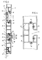
- Figures 5 to 7 show another embodiment of the device, using blades 2 no longer nailed or screwed directly against a wall, but hung on a support structure comprising metal uprights 28, provided with hooks 29 arranged in a regular pitch and turned upwards.
- the uprights 28 are interconnected by horizontal stiffeners 30, between which can also be mounted intermediate uprights 31, also provided with hooks 29.
- the blades 2 are all provided, on their rear wall 8, with two longitudinal hooking notches 32 allowing their direct fixing by interlocking on the hooks 29 of the uprights 28 and 31.
- a panel is thus formed consisting of blades 2 juxtaposed.
- each blade 2 has, hollowed out in its front wall 7, a "T" groove 4 provided with four electrical conductors 14, 15, 16 and 17, while similar grooves, also provided with conductors, are formed at the junction of two adjacent blades 2. All these grooves 4 can receive basic modules 5, supporting and supplying any lighting fixtures 6 themselves, this in a manner identical to the detailed description given above with reference to FIGS. 1 to 4.
- This latter embodiment allows the blades 2 to be put in place more quickly than in the case of nailed or screwed blades.
- it allows the presentation of articles not only against a wall, but also in the middle of a store for example, insofar as the supporting structure comprising the uprights 28 and 31 can be fixed not only against a wall, but still to any other fixed support, for example between the floor and the ceiling, or on shop furniture of the "gondola" type.
Abstract
Description
La présente invention concerne un dispositif d'exposition ou de présentation, du genre de ceux constitués par des lames multiples justaposables, réalisées sous la forme de profilés alvéolés en matière synthétique, ces lames étant aptes à être posées et fixées contre un mur ou une autre paroi plane, ou encore contre des supports tels que montants concus à cet effet, les bords longitudinaux de deux lames consécutives s'emboîtant l'un dans l'autre, et des rainures longitudinales, aptes à recevoir des accessoires, étant formées sur les lames et/ou à la jonction de ces lames.The present invention relates to an exhibition or presentation device, of the type constituted by multiple justaposable blades, produced in the form of honeycombed profiles in synthetic material, these blades being able to be placed and fixed against a wall or another. flat wall, or against supports such as uprights designed for this purpose, the longitudinal edges of two consecutive blades fitting into each other, and longitudinal grooves, suitable for receiving accessories, being formed on the blades and / or at the junction of these blades.
Un tel système de lames multiples juxtaposables est connu par le brevet français N° 1460705. Comme le décrit ce document, chaque lame présente sur l'un de ses bords une lèvre de clouage ou vissage, à travers laquelle peuvent être enfoncés des clous ou vis de fixation de la lame sur un mur ; la lèvre de clouage est recouverte par un bord de la lame suivante, qui est fixée sur le mur de la même manière que la précédente par son bord opposé, et ainsi de suite... Un système analogue se trouve aussi décrit dans le brevet US N° 4607753.Such a system of multiple juxtaposable blades is known from French Patent No. 1460705. As described in this document, each blade has on one of its edges a nailing or screwing lip, through which nails or screws can be driven fixing the blade to a wall; the nailing lip is covered by an edge of the next blade, which is fixed to the wall in the same way as the previous one by its opposite edge, and so on ... A similar system is also described in the US patent No. 4607753.
Ce système de lames juxtaposables est actuellement utilisé comme dispositif d'exposition ou de présentation, dans des stands d'expositions, des magasins de vente, des vitrines... Dans cette application, des accessoires purement "mécaniques", tels que broches, consoles ou étagères, viennent s'accrocher dans des rainures longitudinales formées sur les lames et/ou à la jonction de ces lames, lesdits accessoires permettant de suspendre ou de poser les articles à exposer ou à présenter, certains accessoires étant, par leur forme spécifique, adaptés à des articles particuliers tels que vêtements, chaussures, matériel audio-visuel, etc...This system of juxtaposable blades is currently used as an exhibition or presentation device, in exhibition stands, sales stores, display cases ... In this application, purely "mechanical" accessories, such as pins, consoles or shelves, hang in longitudinal grooves formed on the blades and / or at the junction of these blades, said accessories making it possible to suspend or place the articles to be exhibited or to be presented, certain accessories being, by their specific shape, suitable for specific items such as clothing, shoes, audio-visual equipment, etc.
Lorsqu'un dispositif d'exposition ou de présentation de ce genre nécessite un éclairage, les alimentations électriques se font habituellement par l'intermédiaire de prises de courant encastrées au milieu d'une lame spécifique, de conception spéciale. Ceci complique la structure du dispositif, en rompant la continuité des profilés constituant les lames. Surtout, de tels moyens d'alimentation électriques sont positionnés de façon ponctuelle et invariable, et ne permettent pas de disposer d'une possibilité de branchement électrique en des points quelconques, en nombre illimité, librement choisis et éventuellement modifiables.When such an exhibition or display device requires lighting, power is usually supplied by through sockets embedded in the middle of a specific blade, of special design. This complicates the structure of the device, by breaking the continuity of the sections constituting the blades. Above all, such electrical supply means are positioned in a punctual and invariable manner, and do not allow to have a possibility of electrical connection at any point, in unlimited number, freely chosen and possibly modifiable.
Par ailleurs, il existe des "rails" qui permettent de monter et d'alimenter en électricité des accessoires tels que des spots d'éclairage, dont l'ensemble y compris la fixation est spécialement conçu pour s'adapter sur le profil du rail. On connaît aussi des systèmes dits par "électrobandes" qui permettent de positionner des prises de courant sur une bande d'alimentation électrique. Ces systèmes existants autorisent un libre choix des points de montage ou d'alimentation d'accessoires électriques, mais ils ne constituent pas par eux-mêmes des dispositifs d'exposition ou de présentation, et ne permettent pas la fixation et l'alimentation d'accessoires standard, sans adaptation particulière.In addition, there are "rails" which make it possible to mount and supply electricity to accessories such as spotlights, the assembly including the fixing of which is specially designed to adapt to the profile of the rail. There are also known systems known as "electrostrips" which make it possible to position sockets on an electrical supply strip. These existing systems allow a free choice of mounting points or supply of electrical accessories, but they do not by themselves constitute exhibition or presentation devices, and do not allow the fixing and supply of standard accessories, without particular adaptation.
Dans le brevet US N° 4747025 est décrit un panneau plein d'exposition ou de présentation, réalisé d'une seule pièce, dans lequel sont creusées des rainures parallèles permettant le montage de moyens d'éclairage électriques, alimentés sous basse tension par l'intermédiaire d'un transformateur abaisseur. La fixation mécanique et l'alimentation électrique de chaque lampe s'effectuent entre deux rainures consécutives du panneau, des conducteurs électriques longitudinaux étant disposés extérieurement, à la surface du panneau, en bordure des rainures.In US Patent No. 4,747,025 is described a full display panel or presentation, made in one piece, in which are dug parallel grooves for mounting electrical lighting means, supplied under low voltage by the through a step-down transformer. The mechanical fixing and the electrical supply of each lamp take place between two consecutive grooves of the panel, longitudinal electrical conductors being arranged externally, on the surface of the panel, at the edge of the grooves.
Dans un tel système connu, les conducteurs électriques d'alimentation sont donc directement accessibles, et ne se trouvent pas protégés, ce qui interdit toute utilisation du système sous des tensions électriques habituelles (soit 220 volts pour la France). Ainsi, ce système est limité dans son utilisation à des appareils d'éclairage spécifiques, fonctionnant sous basse tension et destinés à éclairer des objets. Par contre, le système du brevet US N° 4747025 n'est pas du tout adapté à l'alimentation électrique de lampes fonctionnant sous une tension normale, et ainsi ce système ne peut constituer un dispositif d'exposition ou de présentation d'appareils d'éclairage qui, par eux-mêmes, seraient d'un type courant.In such a known system, the electrical supply conductors are therefore directly accessible, and are not protected, which prohibits any use of the system under usual electrical voltages (i.e. 220 volts for France). Thus, this system is limited in its use to specific lighting devices, operating under low voltage and intended to illuminate objects. On the other hand, the system of US Pat. No. 4,747,025 is not at all suitable for the electrical supply of lamps operating under normal voltage, and thus this system cannot constitute a device for exposing or presenting apparatus lighting which, by themselves, would be of a common type.
La présente invention vise à éviter les inconvénients des divers systèmes existants rappelés ci-dessus, en fournissant un dispositif d'exposition ou de présentation à lames multiples juxtaposables, avec des moyens intégrés aux lames pour l'alimentation électrique d'appareils d'éclairage, ces moyens permettant un libre choix de la position des appareils d'éclairage tout en apportant une facilité d'utilisation extrême et en assurant une sécurité satisfaisante, par une protection appropriée des conducteurs électriques, pour permettre son utilisation avec des lampes alimentées sous une tension normale.The present invention aims to avoid the drawbacks of the various existing systems mentioned above, by providing an exhibition or presentation device with multiple juxtaposable blades, with means integrated into the blades for the electrical supply of lighting devices, these means allowing a free choice of the position of the lighting fixtures while providing extreme ease of use and ensuring satisfactory safety, by appropriate protection of the electrical conductors, to allow its use with lamps supplied with normal voltage .
A cet effet, l'invention a essentiellement pour objet un dispositif d'exposition ou de présentation du genre précisé plus haut avec moyens combinés d'accrochage et d'alimentation électrique pour appareils d'éclairage, dans lequel des conducteurs électriques d'alimentation, s'étendant longitudinalement, sont logés dans des gorges longitudinales ménagées dans les parois des rainures formées sur les lames et/ou dans les régions des bords de ces lames qui délimitent une rainure lorsque deux lames consécutives sont emboîtées, tandis que sont prévus, pour le montage d'appareils d'éclairage, des modules de base amovibles aptes à être introduits et retenus dans lesdites rainures, chaque module de base comportant des contacts électriques coopérant avec les conducteurs électriques intégrés aux lames, et une partie prévue pour la fixation d'un appareil d'éclairage quelconque.To this end, the subject of the invention is essentially an exhibition or presentation device of the kind specified above with combined attachment and electrical supply means for lighting devices, in which electrical supply conductors, extending longitudinally, are housed in longitudinal grooves formed in the walls of the grooves formed on the blades and / or in the regions of the edges of these blades which delimit a groove when two consecutive blades are fitted, while provision is made for the mounting of lighting fixtures, removable base modules capable of being inserted and retained in said grooves, each base module comprising contacts electrical cooperating with the electrical conductors integrated in the blades, and a part provided for fixing any lighting fixture.
Ainsi, on obtient un dispositif d'exposition ou de présentation intégrant une alimentation électrique, constituée essentiellement par des conducteurs électriques longitudinaux incorporés aux profilés constituant les lames. La réalisation de ces profilés en matière synthétique assure directement l'isolation électrique desdits conducteurs. De plus, le logement de ces conducteurs en position "interne" à l'intérieur de gorges, dans des rainures possédant avantageusement un profil en "T", assure la sécurité indispensable, notamment si lesdits conducteurs sont disposés dans les régions des deux points extrêmes symétriques du profil en "T" des rainures, de façon invisible et non accessible directement. Le dispositif proposé satisfait ainsi aux normes de sécurité, pour une utilisation sous tension normale, notamment pour l'exposition ou la présentation d'appareils d'éclairage du commerce, dont l'attrait commercial est alors renforcé par une présentation "en fonctionnement".Thus, an exposure or presentation device is obtained integrating an electrical supply, consisting essentially of longitudinal electrical conductors incorporated in the sections constituting the blades. The production of these plastic profiles provides direct electrical insulation of said conductors. In addition, the housing of these conductors in the "internal" position inside grooves, in grooves advantageously having a "T" profile, provides the essential security, especially if said conductors are arranged in the regions of the two extreme points. symmetrical of the "T" profile of the grooves, invisible and not directly accessible. The proposed device thus meets safety standards, for use under normal voltage, in particular for the exhibition or presentation of commercial lighting fixtures, the commercial appeal of which is then reinforced by a presentation "in operation".
Avantageusement, chaque module de base comprend une plaque de support pour un appareil d'éclairage, reliée par un court axe central à une patte de fixation pourvue des contacts électriques coopérant avec les conducteurs électriques intégrés aux lames, la patte de fixation étant apte à être introduite dans une rainure en "T" et, par une rotation d'environ un quart de tour, à être retenue dans la rainure en "T", tout en amenant les contacts électriques en pression sur les conducteurs correspondants.Advantageously, each basic module comprises a support plate for a lighting device, connected by a short central axis to a fixing lug provided with electrical contacts cooperating with the electrical conductors integrated in the blades, the fixing lug being able to be introduced into a "T" groove and, by a rotation of about a quarter of a turn, to be retained in the "T" groove, while bringing the electrical contacts under pressure on the corresponding conductors.
Les modules de base, ainsi constitués et mis en place, permettent de fixer et d'alimenter instantanément n'importe quel appareil d'éclairage, sans autre branchement et en toute simplicité et sécurité, quelle que soit la position de cet appareil d'éclairage sur le panneau constitué par les lames juxtaposées. Le déplacement d'un module de base d'une position vers une autre s'effectue de façon rapide, et l'éclairage s'effectue instantanément au nouvel emplacement choisi. La plaque de support de chaque module de base peut recevoir tout type d'appareil d'éclairage, le cas échéant avec interposition d'éléments d'adaptation interchangeables. La forme spécifique de ce module permet éventuellement un positionnement pour "suspendre" l'appareil d'éclairage, si les lames sont installées horizontalement en plafond.The basic modules, thus constituted and put in place, make it possible to instantly fix and supply any lighting fixture, without any other connection and with ease and security, whatever or the position of this lighting device on the panel formed by the juxtaposed slats. Moving a basic module from one position to another takes place quickly, and lighting is instantaneous at the new location chosen. The support plate of each base module can receive any type of lighting fixture, if necessary with the interposition of interchangeable adapter elements. The specific shape of this module possibly allows positioning to "hang" the lighting fixture, if the slats are installed horizontally in the ceiling.
Par ailleurs, les conducteurs électriques parcourent les lames longitudinalement, sur toute leur longueur, et n'altèrent pas le caractère de profilés de longueur indéfinie que possèdent ces lames. La fabrication du dispositif selon l'invention reste donc rationnelle et économique.Furthermore, the electrical conductors run through the blades longitudinally, over their entire length, and do not alter the character of profiles of indefinite length that these blades have. The manufacture of the device according to the invention therefore remains rational and economical.
On notera aussi que les conducteurs électriques dissimulés dans les rainures, constituant un système d'alimentation électrique invisible, n'affectent pas l'esthétique du dispositif, ce qui est important pour un dispositif destiné à l'exposition ou à la présentation.It will also be noted that the electrical conductors concealed in the grooves, constituting an invisible electrical supply system, do not affect the aesthetics of the device, which is important for a device intended for the exhibition or presentation.
De toute façon, l'invention sera mieux comprise et d'autres caractéristiques seront mises en évidence à l'aide de la description qui suit, en référence au dessin schématique annexé représentant, à titre d'exemples, deux formes d'exécution de ce dispositif d'exposition ou de présentation avec moyens combinés d'accrochage et d'alimentation électrique pour appareils d'éclairage :
- Figure 1 est une vue d'ensemble, en perspective, d'un dispositif d'exposition ou de présentation conforme à la présente invention dans une première forme de réalisation, avec indication de plusieurs modules de base fixés sur les lames ;
- Figure 2 est une vue en perspective, avec partie arrachée, montrant le détail d'un module de base ;
- Figure 3 est une vue en coupe du dispositif de figure 1, avec indication du principe de montage des lames ;
- Figure 4 est une vue en coupe partielle d'une lame, à plus grande échelle, montrant le détail de ses conducteurs électriques ;
- Figure 5 est une vue partielle en perspective d'un dispositif d'exposition ou de présentation conforme à la présente invention, dans une deuxième forme de réalisation ;
- Figures 6 et 7 illustrent, à plus grande échelle, les détails de structure et le principe de montage des lames, dans la forme de réalisation selon la figure 5.
- Figure 1 is an overview, in perspective, of an exhibition or presentation device according to the present invention in a first embodiment, with indication of several basic modules fixed on the blades;
- Figure 2 is a perspective view, with part broken away, showing the detail of a basic module;
- Figure 3 is a sectional view of the device of Figure 1, with indication of the principle of mounting the blades;
- Figure 4 is a partial sectional view of a blade, on a larger scale, showing the detail of its electrical conductors;
- Figure 5 is a partial perspective view of an exhibition or presentation device according to the present invention, in a second embodiment;
- Figures 6 and 7 illustrate, on a larger scale, the structural details and the mounting principle of the blades, in the embodiment according to Figure 5.
Comme le montre la figure 1, le dispositif considéré est fixé ici contre un mur 1, et il comprend des lames multiples 2 juxtaposables, disposées horizontalement contre le mur 1, auquel elles sont fixées par clouage ou vissage comme indiqué en 3. Sur les lames 2, et à la jonction de ces lames 2, sont formées des rainures horizontales 4, qui reçoivent :
- d'une part, de manière connue en soi et non représentée, des accessoires de support ou de suspension pour des articles à exposer ou à présenter ;
- d'autre part, selon la présente invention, des modules de
base 5 amovibles utilisés pour l'accrochage et l'alimentation électrique d'appareils d'éclairage, tels qu'unelampe 6.
- on the one hand, in a manner known per se and not shown, support or suspension accessories for articles to be displayed or presented;
- on the other hand, according to the present invention,
removable base modules 5 used for hanging and supplying power to lighting fixtures, such as alamp 6.
Chaque lame 2 est constituée par un profilé alvéolé en matière synthétique isolante, bien visible sur la figure 3, avec une paroi antérieure 7, une paroi postérieure 8 parallèle à la paroi antérieure 7, et un certain nombre de cloisons internes 9 qui relient les parois antérieure 7 et postérieure 8 en délimitant des alvéoles tubulaires 10.Each
Sur un bord longitudinal de la lame 2 (ici le bord supérieur), la paroi postérieure 8 est prolongée pour former une lèvre de clouage ou vissage 11, prévue pour être traversée par les clous ou vis 3 de fixation au mur 1. L'autre bord de la lame 2 (ici le bord inférieur) possède un profil 12 complémentaire de celui de la lèvre de clouage ou vissage 11, de manière à permettre un emboîtement de deux lames 2 consécutives.On a longitudinal edge of the blade 2 (here the upper edge), the
La figure 3 illustre plus précisément le mode de fixation des lames 2. La lame 2 inférieure peut être emboîtée par son bord inférieur sur un élément de.départ 13, situé à la base du panneau à réaliser. Le bord supérieur de cette première lame est fixé par les clous ou vis 3 sur le mur 1, après quoi la deuxième lame 2 est emboîtée sur la lèvre de clouage ou vissage 11, puis fixée elle-même par clouage ou vissage, et ainsi de suite...FIG. 3 illustrates more precisely the method of fixing the
Chaque lame 2 comporte, creusée sensiblement suivant son axe médian longitudinal, une rainure 4 dont le profil présente une forme en "T", la rainure 4 débouchant à l'extérieur par une fente longitudinale relativement étroite. De plus, les profils des bords supérieur et inférieur des lames 2 procurent, à la jonction de deux lames 2 consécutives emboîtées l'une dans l'autre, une autre rainure 4 qui possède un profil en "T" idertique au précédent.Each
Comme le montre encore plus particulièrement la figure 4, chaque rainure 4 (située sur une lame 2 ou à la jonction de deux lames 2) reçoit quatre conducteurs électriques 14,15,16 et 17, sous forme de fils métalliques de section circulaire ou autre logés respectivement dans quatre gorges longitudinales de profil correspondant, ménagées dans la paroi de cette rainure 4 :
- un conducteur neutre 14 est logé dans une première gorge, formée au point extrême le plus haut de la rainure 4 de profil en "T" ;
- un conducteur de
phase 15 est logé dans une deuxième gorge, formée au point extrême le plus bas de la rainure 4 de profil en "T", donc au point extrême symétrique du précédent ; - un conducteur de
terre 16 est logé dans une troisième gorge, formée entre le conducteur neutre 14 et la fente formant le débouché de la rainure 4, en regard du fond de cette rainure ; - un autre conducteur de
terre 17 est logé dans une quatrième gorge, formée entre le conducteur dephase 15 et la fente formant le débouché de la rainure 4, en regard du fond de cette rainure.
- a
neutral conductor 14 is housed in a first groove, formed at the highest end point of the groove 4 with a "T"profile; - a
phase conductor 15 is housed in a second groove, formed at the lowest end point of the groove 4 in profile in "T", therefore at the symmetrical end point of the previous one; - an
earth conductor 16 is housed in a third groove, formed between theneutral conductor 14 and the slot forming the outlet of the groove 4, facing the bottom of this groove; - another
earth conductor 17 is housed in a fourth groove, formed between thephase conductor 15 and the slot forming the outlet of the groove 4, facing the bottom of this groove.
Les quatre gorges sont ouvertes vers l'intérieur de la rainure 4, de telle sorte que les conducteurs électriques correspondants 14 à 17 présentent tous une zone découverte, pouvant localement être mise en contact avec d'autres éléments électriquement conducteurs. Les conducteurs neutre 14 et de phase 15 sont encastrés de telle manière que seul un élément conducteur adéquat peut venir à leur contact, assurant ainsi une sécurité accrue. Par contre, les conducteurs de terre 16 et 17 sont légèrement en saillie, pour faciliter leur contact avec tout objet métallique qui serait introduit dans la rainure 4. Bien entendu, ces conducteurs de terre 16 et 17 renforcent encore la sécurité du dispositif.The four grooves are open towards the inside of the groove 4, so that the corresponding
Le module de base 5, notamment visible sur la figure 2, comprend une plaque de support 18 et une patte de fixation 19, reliées entre elles par un court axe central 20. La partie formée par la patte de fixation 19 et par l'axe central de liaison 20 reconstitue le profil en "T" d'une rainure 4.The
La patte de fixation 19, de forme allongée, comporte à une extrémité un premier contact 21 pour neutre, et à son extrémité opposée un contact 22 pour phase. Sur sa face tournée vers la plaque de support 18, la patte de fixation 19 est encore pourvue, dans l'exemple représenté, de deux contacts de terre 23 et 24, symétriques l'un de l'autre par rapport à l'axe central 20. Le nombre de contacts de terre peut être ramené à un contact unique, sans altérer la sécurité du dispositif.The fixing
Dans l'axe central 20 sont noyés des conducteurs électriques, raccordés du côté de la patte de fixation 19 aux différents contacts 21 à 24. Ces conducteurs comprennent notamment un conducteur de phase 25 et un conducteur neutre 26, dont les extrémités respectives situées extérieurement forment des bornes pour le branchement d'un appareil d'éclairage, fixé sur la plaque de support 18. Ils peuvent être complétés par un conducteur et une borne de terre 27 (voir figure 2).In the
Pour la mise en place d'un module de base 5, la patte de fixation 19 de celui-ci est d'abord engagée dans la rainure 4, parallèlement à la fente formant le débouché de cette rainure. Puis, par un mouvement de rotation d'un quart de tour de tout le module de base 5, la patte de fixation 19 est amenée en position transversale par rapport à la rainure 4.For the establishment of a
Dans cette position, la patte 19 assure d'une part la fixation mécanique du module de base 5, la plaque 18 formant la contrepartie de cette patte 19 pour immobiliser le module 5. D'autre part, ladite patte de fixation 19 vient s'appliquer, par ses contacts électriques 21,22,23 et 24, contre les conducteurs électriques respectifs 14,15,16 et 17 incorporés dans la paroi de la rainure 4. Ainsi, le module de base 5 assure de façon simultanée l'accrochage mécanique de l'appareil d'éclairage concerné sur les lames 2, et l'alimentation électrique de cet appareil d'éclairage, préalablement fixé sur la plaque 18 et correctement connecté aux bornes précitées.In this position, the
Ce module de base 5 peut être aussi détaché des lames 2 par un simple mouvement de rotation d'un quart de tour, puis replacé sur les mêmes lames, en n'importe quel emplacement, par un mouvement inverse, chaque nouvel emplacement ainsi choisi assurant toujours de la même façon d'une part la fixation mécanique, d'autre part l'alimentation électrique.This
Ce qui vient d'être décrit par un seul module de base 5 peut être répété à l'identique pour un nombre quelconque de modules de base. Ainsi, comme l'illustre la figure 1, un certain nombre de modules de base 5 peuvent être disposés, selon toute configuration désirée, dans les différentes rainures 4 formées sur les lames 2 et à la jonction de ces lames 2, pour l'accrochage et l'alimentation électrique d'une pluralité d'appareils d'éclairage.What has just been described by a single
L'alimentation électrique générale du dispositif doit, bien entendu, amener le courant électrique aux conducteurs insérés dans les différentes rainures 4. Cette alimentation générale se fait soit en façade par un module spécial, adapté à cette fonction, soit par un élément latéral spécifique, situé à une extrémité des lames 2.The general electrical supply of the device must, of course, bring the electric current to the conductors inserted in the different grooves 4. This general supply is made either on the front by a special module, adapted to this function, or by a specific lateral element, located at one end of the
Les figures 5 à 7 montrent une autre forme de réalisation du dispositif, utilisant des lames 2 non plus clouées ou vissées directement contre une paroi, mais accrochées à une structure porteuse comprenant des montants métalliques 28, pourvus de crochets 29 disposés selon un pas régulier et tournés vers le haut. Les montants 28 sont reliés entre eux par des raidisseurs horizontaux 30, entre lesquels peuvent encore être montés des montants intermédiaires 31, eux aussi pourvus de crochets 29.Figures 5 to 7 show another embodiment of the device, using
Les lames 2 sont toutes pourvues, sur leur paroi postérieure 8, de deux échancrures longitudinales d'accrochage 32 permettant leur fixation directe par emboîtement sur les crochets 29 des montants 28 et 31. Après accrochage d'une première lame 2, comme illustré aux figures 5 et 6, la lame 2 suivante est mise en place en s'emboîtant dans la précédente tout en s'accrochant aux montants 28, et ainsi de suite... On forme ainsi un panneau constitué de lames 2 juxtaposées. Comme précédemment, chaque lame 2 comporte, creusée dans sa paroi antérieure 7, une rainure en "T" 4 munie de quatre conducteurs électriques 14,15,16 et 17, tandis que des rainures analogues, également pourvues de conducteurs, sont formées à la jonction de deux lames 2 adjacentes. Toutes ces rainures 4 peuvent recevoir des modules de base 5, supportant et alimentant eux-mêmes des appareils d'éclairage 6 quelconques, ceci d'une manière identique à la description détaillée donnée ci-dessus en référence aux figures 1 à 4.The
Cette dernière forme d'exécution permet une mise en place des lames 2 d'une manière plus rapide que dans le cas de lames clouées ou vissées. De plus, elle permet la présentation d'articles non seulement contre un mur, mais aussi au milieu d'un magasin par exemple, dans la mesure où la structure porteuse comprenant les montants 28 et 31 peut être fixée non seulement contre un mur, mais encore à tout autre support fixe, par exemple entre le sol et le plafond, ou sur un mobilier de magasin du type "gondole".This latter embodiment allows the
L'on ne s'éloignerait pas du cadre de l'invention :
- en modifiant les formes de détail des lames avec conducteurs électriques intégrés, par exemple par une modification de la disposition des cloisons intérieures délimitant les alvéoles de ces lames, ou encore une modification du nombre des conducteurs électriques de chaque lame ;
- en réalisant le dispositif avec des lames orientées non pas horizontalement, mais selon une direction différente, et fixées contre un mur ou une autre paroi située dans un plan vertical, incliné ou horizontal, ainsi qu'en fixant les lames sur d'autres types de supports que ceux décrits ;
- en complétant ce dispositif par tous accessoires, venant notamment se monter sur les modules de base, ce qui est d'ailleurs avantageusement prévu pour l'exploitation aisée du dispositif au vu de la multiplicité des appareils d'éclairage pouvant être amenés à être présentés, y compris des accessoires tels que bornes de branchement ou prises de courant.
- by modifying the forms of detail of the blades with integrated electrical conductors, for example by a modification of the arrangement of the internal partitions delimiting the cells of these blades, or even a modification of the number of electrical conductors of each blade;
- by making the device with blades oriented not horizontally, but in a different direction, and fixed against a wall or another wall located in a vertical, inclined or horizontal plane, as well as by fixing the blades on other types of supports than those described;
- by supplementing this device with any accessories, in particular coming to be mounted on the basic modules, which is moreover advantageously provided for easy operation of the device in view of the multiplicity of lighting fixtures that can be brought to be presented, including accessories such as connection terminals or sockets.
Claims (7)
Applications Claiming Priority (2)
| Application Number | Priority Date | Filing Date | Title |
|---|---|---|---|
| FR9406647A FR2720247B1 (en) | 1994-05-26 | 1994-05-26 | Exhibition or display device with combined hanging and power supply means for lighting fixtures. |
| FR9406647 | 1994-05-26 |
Publications (2)
| Publication Number | Publication Date |
|---|---|
| EP0683998A1 true EP0683998A1 (en) | 1995-11-29 |
| EP0683998B1 EP0683998B1 (en) | 2002-04-03 |
Family
ID=9463722
Family Applications (1)
| Application Number | Title | Priority Date | Filing Date |
|---|---|---|---|
| EP19950420136 Expired - Lifetime EP0683998B1 (en) | 1994-05-26 | 1995-05-24 | Exhibition or display device with means for both attachment and power supply of light sources |
Country Status (3)
| Country | Link |
|---|---|
| EP (1) | EP0683998B1 (en) |
| DE (1) | DE69526137T2 (en) |
| FR (1) | FR2720247B1 (en) |
Cited By (13)
| Publication number | Priority date | Publication date | Assignee | Title |
|---|---|---|---|---|
| WO1999035941A1 (en) * | 1998-01-20 | 1999-07-22 | Storewall, Llc | Slatwall display system |
| FR2793667A1 (en) * | 1999-05-19 | 2000-11-24 | Tipsy Creation | Display unit for goods in shop comprises series of shelves centered on vertical wall using centering studs, and secured to wall using strips, and protrusion sliding in groove |
| WO2005044061A1 (en) * | 2003-11-11 | 2005-05-19 | Vks Inventa A/S | Suspension arrangement |
| EP2292120A1 (en) * | 2009-09-08 | 2011-03-09 | Dula-Werke Dustmann & Co. GmbH | Device for carrying objects |
| EP2220965A3 (en) * | 2009-02-19 | 2012-04-25 | Juvema Ag | Presentation system with carrier profile rail |
| WO2012113528A1 (en) * | 2011-02-23 | 2012-08-30 | Dula-Werke Dustmann & Co. Gmbh | Device for releasably fastening an element to a wall or the like |
| WO2014118528A1 (en) * | 2013-01-30 | 2014-08-07 | Artform International Limited | Display panel and method of manufacture |
| US8979296B2 (en) | 2011-03-08 | 2015-03-17 | Dci Marketing, Inc. | Illuminated shelving |
| US10130196B2 (en) | 2014-08-07 | 2018-11-20 | Artform International Limited | Product display shelf, system and method |
| US10405674B2 (en) | 2016-03-23 | 2019-09-10 | Retail Space Solutions Llc | Low product indicator for self facing merchandiser and related methods |
| EP3659471A1 (en) * | 2018-11-27 | 2020-06-03 | OZ lighting GmbH | Conductor rail system and wall or ceiling plate therewith |
| US10702076B2 (en) | 2016-01-18 | 2020-07-07 | Atlas Bolt & Screw Company Llc | Sensors, devices, adapters and mating structures for merchandisers and related methods |
| US10952548B2 (en) | 2016-10-18 | 2021-03-23 | Retail Space Solutions Llc | Illuminated merchandiser, retrofit kit and related methods |
Families Citing this family (1)
| Publication number | Priority date | Publication date | Assignee | Title |
|---|---|---|---|---|
| FR3061224A1 (en) * | 2016-12-22 | 2018-06-29 | Bernard Proot | ELECTRICALLY CONDUCTIVE FINISHING PROFILE |
Citations (5)
| Publication number | Priority date | Publication date | Assignee | Title |
|---|---|---|---|---|
| FR1460705A (en) | 1965-06-11 | 1966-12-10 | Wall covering slat | |
| US4607753A (en) | 1983-06-28 | 1986-08-26 | Ready Metal Manufacturing Company | Slotted wall merchandise display panel |
| US4747025A (en) | 1986-09-30 | 1988-05-24 | Barton Daniel W | Low voltage lighting fixture with track electrodes |
| EP0332377A2 (en) * | 1988-03-07 | 1989-09-13 | Adco Enterprises, Inc. | Display racks and brackets therefor |
| EP0522185A1 (en) * | 1990-07-03 | 1993-01-13 | Powerlite Electrical Products Ltd | Lighting track system |
-
1994
- 1994-05-26 FR FR9406647A patent/FR2720247B1/en not_active Expired - Lifetime
-
1995
- 1995-05-24 EP EP19950420136 patent/EP0683998B1/en not_active Expired - Lifetime
- 1995-05-24 DE DE1995626137 patent/DE69526137T2/en not_active Expired - Lifetime
Patent Citations (5)
| Publication number | Priority date | Publication date | Assignee | Title |
|---|---|---|---|---|
| FR1460705A (en) | 1965-06-11 | 1966-12-10 | Wall covering slat | |
| US4607753A (en) | 1983-06-28 | 1986-08-26 | Ready Metal Manufacturing Company | Slotted wall merchandise display panel |
| US4747025A (en) | 1986-09-30 | 1988-05-24 | Barton Daniel W | Low voltage lighting fixture with track electrodes |
| EP0332377A2 (en) * | 1988-03-07 | 1989-09-13 | Adco Enterprises, Inc. | Display racks and brackets therefor |
| EP0522185A1 (en) * | 1990-07-03 | 1993-01-13 | Powerlite Electrical Products Ltd | Lighting track system |
Cited By (20)
| Publication number | Priority date | Publication date | Assignee | Title |
|---|---|---|---|---|
| WO1999035941A1 (en) * | 1998-01-20 | 1999-07-22 | Storewall, Llc | Slatwall display system |
| FR2793667A1 (en) * | 1999-05-19 | 2000-11-24 | Tipsy Creation | Display unit for goods in shop comprises series of shelves centered on vertical wall using centering studs, and secured to wall using strips, and protrusion sliding in groove |
| WO2005044061A1 (en) * | 2003-11-11 | 2005-05-19 | Vks Inventa A/S | Suspension arrangement |
| EP2220965A3 (en) * | 2009-02-19 | 2012-04-25 | Juvema Ag | Presentation system with carrier profile rail |
| EP2292120A1 (en) * | 2009-09-08 | 2011-03-09 | Dula-Werke Dustmann & Co. GmbH | Device for carrying objects |
| RU2576583C2 (en) * | 2011-02-23 | 2016-03-10 | Дула-Верке Дустманн Унд Ко. Гмбх | Device for detachable fixation of element to wall or similar |
| WO2012113528A1 (en) * | 2011-02-23 | 2012-08-30 | Dula-Werke Dustmann & Co. Gmbh | Device for releasably fastening an element to a wall or the like |
| US9775447B2 (en) | 2011-03-08 | 2017-10-03 | Dci Marketing, Inc. | Illuminated shelving |
| US8979296B2 (en) | 2011-03-08 | 2015-03-17 | Dci Marketing, Inc. | Illuminated shelving |
| GB2512810A (en) * | 2013-01-30 | 2014-10-15 | Artform Internat Ltd | Display panel and method of manufacture |
| WO2014118528A1 (en) * | 2013-01-30 | 2014-08-07 | Artform International Limited | Display panel and method of manufacture |
| GB2512810B (en) * | 2013-01-30 | 2018-07-04 | Artform Int Ltd | Display panel and method of manufacture |
| US10130196B2 (en) | 2014-08-07 | 2018-11-20 | Artform International Limited | Product display shelf, system and method |
| US10470594B2 (en) | 2014-08-07 | 2019-11-12 | Artform International Limited | Product display shelf, system and method |
| US10702076B2 (en) | 2016-01-18 | 2020-07-07 | Atlas Bolt & Screw Company Llc | Sensors, devices, adapters and mating structures for merchandisers and related methods |
| US10405674B2 (en) | 2016-03-23 | 2019-09-10 | Retail Space Solutions Llc | Low product indicator for self facing merchandiser and related methods |
| US10588427B2 (en) | 2016-03-23 | 2020-03-17 | Retail Space Solutions Llc | Low product indicator for self facing merchandiser and related methods |
| US11291312B2 (en) | 2016-03-23 | 2022-04-05 | Retail Space Solutions Llc | Low product indicator for self facing merchandiser and related methods |
| US10952548B2 (en) | 2016-10-18 | 2021-03-23 | Retail Space Solutions Llc | Illuminated merchandiser, retrofit kit and related methods |
| EP3659471A1 (en) * | 2018-11-27 | 2020-06-03 | OZ lighting GmbH | Conductor rail system and wall or ceiling plate therewith |
Also Published As
| Publication number | Publication date |
|---|---|
| DE69526137D1 (en) | 2002-05-08 |
| FR2720247B1 (en) | 1996-08-02 |
| FR2720247A1 (en) | 1995-12-01 |
| EP0683998B1 (en) | 2002-04-03 |
| DE69526137T2 (en) | 2002-12-12 |
Similar Documents
| Publication | Publication Date | Title |
|---|---|---|
| EP1557118A1 (en) | Shelf arrangement with integrated power supply for illumination devices | |
| EP0683998B1 (en) | Exhibition or display device with means for both attachment and power supply of light sources | |
| EP0587882B1 (en) | Device for the support and power supply of very low voltage lighting | |
| EP0433197A1 (en) | Frame for furniture support, with wire guide means, for electrical and electronic installations | |
| FR2946852A1 (en) | Display i.e. point-of-purchase advertising type electric display, for displaying articles in shop, has permanent magnets to fix separator on conductive strips, and electric rails respectively connected to supply terminals of light source | |
| EP0551041B1 (en) | Lighting and hanging-up device for carrying objects and modular assembly of such lighting and hanging-up devices | |
| FR2731885A1 (en) | Adjustable shelving unit with in-built lighting for retail display | |
| EP0652398B1 (en) | Elongated lighting system | |
| EP3286497B1 (en) | Illuminating planar mounting device | |
| FR2568984A1 (en) | SELF-LIGHTING SAFETY CIMAISE | |
| FR2960683A1 (en) | LUMINOUS DISPLAY FOR PRODUCTS, IN PARTICULAR MAKE-UP | |
| FR2731332A1 (en) | Display panel anchored to floor ceiling or wall | |
| EP2581658A1 (en) | Luminaire | |
| FR2660491A1 (en) | Electrical supply system and application, especially, to the illumination of objects arranged on display, such as paintings | |
| EP0375654A1 (en) | Assembly comprising an adaptor mounted on an electrical contact-strip | |
| EP0315558B1 (en) | Electrified sliding rail for a mobile electrical socket | |
| EP0786845B1 (en) | Sheath, especially for hospital establishment | |
| CH655990A5 (en) | Lighting device | |
| FR2867314A1 (en) | EQUIPMENT FOR SUSPENSION WITH A CEILING OR SIMILAR STRUCTURE AND ELECTRICAL POWER SUPPLY OF LIGHTING DEVICES | |
| KR200162979Y1 (en) | A picture frame for exhibit support | |
| FR2788106A1 (en) | LIGHTING DEVICE WITH SLIDING RAMP | |
| FR2988532A1 (en) | Supporting foot for cabinet of temporary power distributor that is utilized for e.g. distributing electric current in building site, has upper part and base that are not separated until cabinet is placed on foot to maintain cabinet in place | |
| FR3066652A1 (en) | DEVICE FOR SUSPENSION AND ELECTRICAL SUPPLY, IN PARTICULAR OF A BRIGHT ACCESSORY | |
| FR3066649A1 (en) | DEVICE FOR FASTENING AND ELECTRICALLY CONNECTING LUMINOUS PLATFORM SUPPORTS | |
| FR2807577A1 (en) | Shelf support system with electrical supply includes hollow mounting rails with conductors passing down through rails |
Legal Events
| Date | Code | Title | Description |
|---|---|---|---|
| PUAI | Public reference made under article 153(3) epc to a published international application that has entered the european phase |
Free format text: ORIGINAL CODE: 0009012 |
|
| AK | Designated contracting states |
Kind code of ref document: A1 Designated state(s): DE ES GB IT |
|
| 17P | Request for examination filed |
Effective date: 19960524 |
|
| RAP1 | Party data changed (applicant data changed or rights of an application transferred) |
Owner name: JANNIN, BERNARD Owner name: CARLIN, PATRICK |
|
| RIN1 | Information on inventor provided before grant (corrected) |
Inventor name: CARLIN, PATRICK |
|
| 17Q | First examination report despatched |
Effective date: 19990914 |
|
| 111L | Licence recorded |
Free format text: 19990920 0100 WATTOHM TECHNOLOGIES S.A. |
|
| GRAG | Despatch of communication of intention to grant |
Free format text: ORIGINAL CODE: EPIDOS AGRA |
|
| GRAG | Despatch of communication of intention to grant |
Free format text: ORIGINAL CODE: EPIDOS AGRA |
|
| GRAH | Despatch of communication of intention to grant a patent |
Free format text: ORIGINAL CODE: EPIDOS IGRA |
|
| GRAH | Despatch of communication of intention to grant a patent |
Free format text: ORIGINAL CODE: EPIDOS IGRA |
|
| REG | Reference to a national code |
Ref country code: GB Ref legal event code: IF02 |
|
| GRAA | (expected) grant |
Free format text: ORIGINAL CODE: 0009210 |
|
| AK | Designated contracting states |
Kind code of ref document: B1 Designated state(s): DE ES GB IT |
|
| PG25 | Lapsed in a contracting state [announced via postgrant information from national office to epo] |
Ref country code: IT Free format text: LAPSE BECAUSE OF FAILURE TO SUBMIT A TRANSLATION OF THE DESCRIPTION OR TO PAY THE FEE WITHIN THE PRESCRIBED TIME-LIMIT;WARNING: LAPSES OF ITALIAN PATENTS WITH EFFECTIVE DATE BEFORE 2007 MAY HAVE OCCURRED AT ANY TIME BEFORE 2007. THE CORRECT EFFECTIVE DATE MAY BE DIFFERENT FROM THE ONE RECORDED. Effective date: 20020403 |
|
| REF | Corresponds to: |
Ref document number: 69526137 Country of ref document: DE Date of ref document: 20020508 |
|
| GBT | Gb: translation of ep patent filed (gb section 77(6)(a)/1977) |
Effective date: 20020708 |
|
| PG25 | Lapsed in a contracting state [announced via postgrant information from national office to epo] |
Ref country code: ES Free format text: LAPSE BECAUSE OF FAILURE TO SUBMIT A TRANSLATION OF THE DESCRIPTION OR TO PAY THE FEE WITHIN THE PRESCRIBED TIME-LIMIT Effective date: 20021030 |
|
| PLBE | No opposition filed within time limit |
Free format text: ORIGINAL CODE: 0009261 |
|
| STAA | Information on the status of an ep patent application or granted ep patent |
Free format text: STATUS: NO OPPOSITION FILED WITHIN TIME LIMIT |
|
| 26N | No opposition filed |
Effective date: 20030106 |
|
| PGFP | Annual fee paid to national office [announced via postgrant information from national office to epo] |
Ref country code: DE Payment date: 20110426 Year of fee payment: 17 |
|
| REG | Reference to a national code |
Ref country code: DE Ref legal event code: R119 Ref document number: 69526137 Country of ref document: DE Effective date: 20121201 |
|
| PG25 | Lapsed in a contracting state [announced via postgrant information from national office to epo] |
Ref country code: DE Free format text: LAPSE BECAUSE OF NON-PAYMENT OF DUE FEES Effective date: 20121201 |
|
| PGFP | Annual fee paid to national office [announced via postgrant information from national office to epo] |
Ref country code: GB Payment date: 20140523 Year of fee payment: 20 |
|
| REG | Reference to a national code |
Ref country code: GB Ref legal event code: PE20 Expiry date: 20150523 |
|
| PG25 | Lapsed in a contracting state [announced via postgrant information from national office to epo] |
Ref country code: GB Free format text: LAPSE BECAUSE OF EXPIRATION OF PROTECTION Effective date: 20150523 |